JP2016151397A - Air conditioner - Google Patents
Air conditioner Download PDFInfo
- Publication number
- JP2016151397A JP2016151397A JP2015030114A JP2015030114A JP2016151397A JP 2016151397 A JP2016151397 A JP 2016151397A JP 2015030114 A JP2015030114 A JP 2015030114A JP 2015030114 A JP2015030114 A JP 2015030114A JP 2016151397 A JP2016151397 A JP 2016151397A
- Authority
- JP
- Japan
- Prior art keywords
- electric motor
- fan guard
- air conditioner
- fan
- control device
- Prior art date
- Legal status (The legal status is an assumption and is not a legal conclusion. Google has not performed a legal analysis and makes no representation as to the accuracy of the status listed.)
- Pending
Links
Images


Abstract
Description
本発明は熱交換装置を備えた空気調和機に係り、特に筐体内に設けられ送風機を介して送られる空気と熱交換器を流れる冷媒との間で熱交換する熱交換装置を備えた空気調和機に関するものである。 The present invention relates to an air conditioner equipped with a heat exchange device, and in particular, an air conditioner equipped with a heat exchange device that exchanges heat between air that is provided in a housing and sent through a blower and refrigerant that flows through the heat exchanger. Related to the machine.
一般的に空気調和機は、冷媒が封入された冷媒循環流路に、冷媒を圧縮する圧縮機と、冷媒と室内の空気とを熱交換させる室内熱交換器と、冷媒を減圧する膨張弁と、冷媒と外気とを熱交換させる室外熱交換器とを順次配設してなる冷凍サイクルを備えている。室外熱交換器は、室外熱交換器に空気を送る送風機と共に室外機の筐体内に格納され、また、室内熱交換器は、室内熱交換器に室内の空気を送る送風機と共に室内機の筐体内に格納されている。 In general, an air conditioner includes a compressor that compresses a refrigerant in a refrigerant circulation passage in which the refrigerant is sealed, an indoor heat exchanger that exchanges heat between the refrigerant and indoor air, and an expansion valve that depressurizes the refrigerant. And an refrigeration cycle in which an outdoor heat exchanger for exchanging heat between the refrigerant and the outside air is sequentially provided. The outdoor heat exchanger is stored in the casing of the outdoor unit together with a blower that sends air to the outdoor heat exchanger, and the indoor heat exchanger is inside the casing of the indoor unit together with a blower that sends indoor air to the indoor heat exchanger Stored in
このような構成の空気調和機は、例えば、特開2010-236715号公報(特許文献1)に記載されている。そして、室内機の内部に設けられた室内熱交換器の近傍には、送風機である室内ファンが設置されている。室内ファンは、遠心ファンとそれを回転駆動する回転数可変の電動モータから成っている。室内側制御装置が、インバータ制御装置である室内ファン駆動装置を制御し、室内ファンの運転開始や停止、回転数の変更を行う。 An air conditioner having such a configuration is described in, for example, Japanese Patent Application Laid-Open No. 2010-236715 (Patent Document 1). And the indoor fan which is an air blower is installed in the vicinity of the indoor heat exchanger provided in the inside of an indoor unit. The indoor fan is composed of a centrifugal fan and an electric motor with a variable number of revolutions for driving the centrifugal fan. The indoor control device controls the indoor fan drive device, which is an inverter control device, and starts and stops the operation of the indoor fan and changes the rotational speed.
また、同様に室外機には、室外熱交換器の近くに送風機である室外ファンが設置されている。室外ファンは、プロペラファンとそれを回転駆動する回転数可変の電動モータから構成されている。室外側制御装置が、インバータ制御装置である室外ファン駆動装置を制御し、室外ファンの運転開始や停止、回転数の変更を行う。 Similarly, an outdoor fan, which is a blower, is installed in the outdoor unit near the outdoor heat exchanger. The outdoor fan is composed of a propeller fan and an electric motor with a variable number of revolutions that rotates the propeller fan. The outdoor control device controls the outdoor fan drive device that is an inverter control device, and starts and stops the operation of the outdoor fan, and changes the rotation speed.
尚、室内機は据付場所に対応して様々な形態のものがあるが、近年、特に業務用の分野では、筐体を天井内に埋め込み、天井面に設置された化粧パネルを介して空気の吸い込み、吹き出しを行う、いわゆる天井埋込型空気調和機が主流となっている。 There are various types of indoor units depending on the installation location, but in recent years, especially in the field of business use, the casing is embedded in the ceiling and air is passed through a decorative panel installed on the ceiling surface. So-called ceiling-embedded air conditioners that draw in and blow out are the mainstream.
ところで、特許文献1の図5にもあるように室内機においては、ファンガードとなる吸い込みグリルは化粧パネルから着脱可能であり、フィルタの清掃やファン、電気品箱等のメンテナンスが容易な構造となっている。また、室外機の吹き出し口には、プロペラファンを覆うファンガードとなる吹き出しグリルが設置され、プロペラファンに外部からの障害物が接触しないように保護されている。このように、室内機の吸い込みグリルや室外機の吹き出しグリルのようなファンガードは、回転体であるファンに人や障害物が接触するのを防いで怪我や空気調和機の破損を防止する保護装置である。 Incidentally, as shown in FIG. 5 of Patent Document 1, in the indoor unit, the suction grille serving as a fan guard is detachable from the decorative panel, and has a structure that facilitates cleaning of the filter and maintenance of the fan, the electrical component box, and the like. It has become. In addition, a blow-out grill serving as a fan guard that covers the propeller fan is installed at the blow-out opening of the outdoor unit, and the propeller fan is protected from contact with external obstacles. In this way, fan guards such as indoor unit suction grills and outdoor unit blowout grills prevent people and obstacles from coming into contact with the rotating fan to prevent injury and damage to the air conditioner. Device.
しかしながら、悪戯などでファンガードが故意に外された場合や、清掃作業でファンガードの再装着を失念した場合等であっても、室内機や室外機では運転が継続され、使用者等が気付くまでは保護装置なしの状態でも運転できてしまい、安全上の観点から好ましくないという課題があった。 However, even when the fan guard is deliberately removed due to mischief or when the fan guard is forgotten to be re-installed during cleaning work, etc., the indoor unit or outdoor unit continues to operate and the user notices. Until then, it could be operated even without a protective device, which was not preferable from the viewpoint of safety.
本発明の目的は、室内機や室外機に設けられたファンガードが外れている場合に、室内機や室外機の運転を停止して安全性を向上する新規な空気調和機を提供することにある。 An object of the present invention is to provide a novel air conditioner that improves the safety by stopping the operation of an indoor unit or an outdoor unit when the fan guard provided in the indoor unit or the outdoor unit is removed. is there.
本発明の特徴は、ファンガードの取り付け状態を検出し、ファンガードが取り付けられていないことを検出すると、室外機或いは室外機の電動モータの運転を停止させる、ところにある。 The feature of the present invention resides in that the operation of the outdoor unit or the electric motor of the outdoor unit is stopped when it is detected that the fan guard is attached and the fan guard is not attached.
本発明によれば、室内機や室外機に設けられたファンガードが外れている場合に、室内機や室外機の電動モータの運転を停止することによって安全性を向上することができる。 ADVANTAGE OF THE INVENTION According to this invention, when the fan guard provided in the indoor unit or the outdoor unit is removed, safety can be improved by stopping the operation of the electric motor of the indoor unit or the outdoor unit.
本発明の実施形態について図面を用いて詳細に説明するが、本発明は以下の実施形態に限定されることなく、本発明の技術的な概念の中で種々の変形例や応用例をもその範囲に含むものである。 Embodiments of the present invention will be described in detail with reference to the drawings. However, the present invention is not limited to the following embodiments, and various modifications and application examples are included in the technical concept of the present invention. It is included in the range.
本発明の空気調和機を説明する前に一般的な室内機及び室外機の構成について説明するが、図1は天井埋込型空気調和機の室内機を示し、図2はその室外機を示している。 Before describing the air conditioner of the present invention, the configuration of a general indoor unit and outdoor unit will be described. FIG. 1 shows an indoor unit of a ceiling-embedded air conditioner, and FIG. 2 shows the outdoor unit. ing.
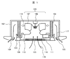
図1において、室内機は周囲に風向板104を備えた吹き出し口105が配設された化粧パネル101と、化粧パネル101に接続された筐体102から構成されている。筐体102内には電動モータ106及び電動モータ106のシャフトに接続された遠心ファン107からなる遠心送風機120が設置され、電動モータ106を運転することにより遠心ファン107が回転する。
In FIG. 1, the indoor unit is composed of a
図1の矢印115に示す様に、室内空気は遠心ファン107の吸い込み口を覆うファンガードとなる吸込みグリル103、吸い込みグリル103に設置されたフィルタ116、筐体102内に設置されたベルマウス110を通して遠心ファン107の吸い込み口に吸い込まれ、矢印118で示されるように遠心ファン107の吐き出し口より吐出される。
As indicated by an
また,遠心送風機120の周囲を取り囲むように室内熱交換器108が配置され,遠心ファン107から吐出された空気は室内熱交換器108で熱交換されたあと、矢印117に示すように吹出口105より室内に吹出される。
An
また、室内熱交換器108の下部には冷房時に室内熱交換器108に生じる結露水を受けるためのドレンパン109が設置されている。更に、ベルマウス110の下面には運転を制御するための図示しない制御基板を収納した電気品箱111が取り付けられている。ここで、ファンガードとなる吸い込みグリル103は化粧パネル101から着脱可能であり、フィルタ116の清掃やファン、電気品箱等のメンテナンスが容易な構造となっている。
In addition, a
一方、室外機は熱交換後の空気を筐体の上部から吹き出す上吹き型や、熱交換後の空気を筐体の前面から吹き出す横吹き型といった形態がある。図2に空気調和機の室外機の構成を示している。この室外機は横吹き型の構成を示している。 On the other hand, the outdoor unit has a form such as an upper blowing type that blows out air after heat exchange from the upper part of the casing, and a horizontal blowing type that blows out air after heat exchange from the front face of the casing. FIG. 2 shows the configuration of the outdoor unit of the air conditioner. This outdoor unit has a horizontal blow type configuration.
図2において、筐体121の内部は仕切板122により、圧縮機123や図示しない制御基板を収納した電気品箱124を収める機械室125と、プロペラファン126と電動モータ127からなる軸流送風機128を備えた送風機室129に分けられている。送風機室129の軸流送風機128の上流には熱交換器130が配置され、電動モータ127を運転することによりプロペラファン126が回転し、熱交換器130を介して周囲の空気を吸込み、筐体に設けられた吹き出し口131より熱交換された空気を吹き出すものである。ここで、吹き出し口131には、プロペラファン126を覆うファンガードとなる吹き出しグリル132が設置され、プロペラファン126に障害物が接触しないように保護されている。
In FIG. 2, the inside of a
上述したように従来の空気調和機においては、悪戯などでファンガードが故意に外された場合や、清掃作業でファンガードの再装着を失念した場合等であっても、室内機や室外機では運転が継続され、使用者等が気付くまでは保護装置なしの状態でも運転できてしまい、安全上の観点から好ましくないという課題があった。 As described above, in the conventional air conditioner, even if the fan guard is intentionally removed due to mischief or when the fan guard is forgotten to be re-installed in the cleaning work, Until the operation is continued and the user or the like notices, the vehicle can be operated even without a protective device, which is not preferable from the viewpoint of safety.
そこで、本発明ではファンガードの取り付け状態(設置状態)を検出し、ファンガードが取り付けられていないことを検出すると、室内機或いは室外機の運転を停止させる構成としたものである。これによれば、室内機や室外機に設けられたファンガードが外れている場合に、室内機や室外機の電動モータの運転を停止することによって安全性を向上することができる。以下、本発明の実施形態について図面を用いて詳細に説明する。 Therefore, the present invention is configured to detect the installation state (installation state) of the fan guard and stop the operation of the indoor unit or the outdoor unit when it is detected that the fan guard is not attached. According to this, when the fan guard provided in the indoor unit or the outdoor unit is removed, safety can be improved by stopping the operation of the electric motor of the indoor unit or the outdoor unit. Hereinafter, embodiments of the present invention will be described in detail with reference to the drawings.
図3は本発明の第1の実施形態である空気調和機の電動モータ運転制御部の概略を表すブロック図である。尚、この図3は空気調和機の室内機の例について示したものであるが、室外機おいても基本的には同一であるので説明は省略する。 FIG. 3 is a block diagram showing an outline of the electric motor operation control unit of the air conditioner according to the first embodiment of the present invention. Although FIG. 3 shows an example of an indoor unit of an air conditioner, the description is omitted because it is basically the same for an outdoor unit.
図3において、制御基板1には電源回路部2、マイクロコンピュータを主体とする制御部3、制御プログラムや演算で使用する制御定数が記憶されたROMや、ワークエリアとして機能するRAM等からなるメモリ部4、電動モータに供給される電流の大きさを検出する電流検出部5が備えられている。電源回路部2は商用電源6から供給を受け、ファン7を回転させるための電動モータ8の駆動回路9に直流電流を供給する。電流検出部5はホール素子を利用したものであり、電源回路部2と駆動回路9の間に接続され、駆動回路9に供給する電動モータの駆動電流を検知する。
In FIG. 3, the control board 1 includes a power
また、制御部3は駆動回路9と接続され、電動モータ8を運転するために必要な情報をやり取りするほか、表示部10を備えたリモコン11と接続され、使用者がリモコン11にて設定した情報を制御部3で受け取り、空気調和機の制御を行ったり、制御部3からリモコン11に送られた運転情報を表示部10に表示したりする。
The
図4に、電動モータ8の回転数と電動モータ8に供給される電流、すなわち電流検出部5にて検出される電流との関係を示している。ファンの回転数は、運転状態によって決められており、「弱運転」状態では回転数N1で回転され、「中運転」状態では回転数N2で回転され、「強運転」状態では回転数N3で回転されるものである。したがって、「弱運転」状態から「中運転」状態に運転状態が変化された時には、電動モータ8の回転数は回転数N1から回転数N2に変更されるものとなる。
FIG. 4 shows the relationship between the number of rotations of the
そして、ファンガードとなる吸い込みグリル103が正常に装着されている通常の場合(以下、通常状態という)は、図4の実線で示すように回転数が増えると電流値が増えるものである。一方、ファンガードとなる吸込みグリル103が外れている場合(以下、異常状態という)も回転数が増えると共に電流値が増えるが、流路抵抗となるファンガードがない分だけ風量が増えるため、電流値としては通常状態の場合に比べて大きくなる。
In a normal case where the
例えば、「弱運転」の回転数がN1の時の通常状態の電流値はI1nであるが、異常状態の電流値はI1aとなり、異常状態の方が電流値は大きくなる。同様に、「中運転」の回転数がN2の時の通常状態の電流値はI2nであるが、異常状態の電流値はI2aとなり、「強運転」の回転数がN3の時の通常状態の電流値はI3nであるが、異常状態の電流値はI3aとなり、いずれの場合も異常状態の方が電流値は大きくなる。 For example, the current value in the normal state when the rotation speed of “weak operation” is N1 is I1n, but the current value in the abnormal state is I1a, and the current value is larger in the abnormal state. Similarly, the current value in the normal state when the rotation speed in “medium operation” is N2 is I2n, but the current value in the abnormal state is I2a, and the current value in the normal state when the rotation speed in “strong operation” is N3. Although the current value is I3n, the current value in the abnormal state is I3a, and in any case, the current value is larger in the abnormal state.
したがって、ファンガードを取り外した状態で、回転数を上昇させていった時の駆動回路9に供給される電流値を、回転数N1、N2、N3のように所定回転数毎に予め求めておき、これを回転数テーブルに記憶させるようにしておく。この電流値は室内機の電動モータ8を停止するための電流閾値として使用されるものである。そして、この回転数テーブルは制御基板のメモリ部(例えば、フラッシュメモリ等)4に記憶されており、制御部3を構成するマイクロコンピュータの制御フローで使用される。尚、マイクロコンピュータの機能等は既に良く知られているので、ここでは詳細な説明を省略する。
Therefore, the current value supplied to the drive circuit 9 when the rotational speed is increased with the fan guard removed is obtained in advance for each predetermined rotational speed, such as the rotational speeds N1, N2, and N3. This is stored in the rotation speed table. This current value is used as a current threshold for stopping the
例えば、マイクロコンピュータにおいては、所定時間毎に割り込みを発生させて異常状態検出プログラムを起動させ、現在のファン7、或いは電動モータ8の回転数を検出し、同時に電流検出部5から駆動回路9に流れ込んでいる現在の電流値を検出する。これらの回転数情報と電流値情報はマイクロコンピュータのRAMに一時的に記憶される。
For example, in a microcomputer, an abnormal state detection program is started at every predetermined time to start an abnormal state detection program, and the current rotational speed of the
一方、マイクロコンピュータは検出された回転数情報からメモリ部4に予め記憶された、「弱運転」の回転数N1、「中運転」の回転数N2、「強運転」の回転数N3に対応した電流閾値(ここでは、ファンガードが外された時の電流値)を読み込む。 On the other hand, the microcomputer corresponds to the rotation speed N1 of “weak operation”, the rotation speed N2 of “medium operation”, and the rotation speed N3 of “strong operation” stored in the memory unit 4 in advance from the detected rotation speed information. The current threshold value (here, the current value when the fan guard is removed) is read.
次にマイクロコンピュータは、RAMに記憶された検出された電流値とメモリ部4に記憶された電流閾値とを比較し、検出された電流値が電流閾値より低ければファンガードが正常に取り付けられていると見做して室内機の運転を継続する。一方、検出された電流値が電流閾値より高ければファンガードが外れていると見做して室内機の電動モータ8の運転を停止する。
Next, the microcomputer compares the detected current value stored in the RAM with the current threshold value stored in the memory unit 4, and if the detected current value is lower than the current threshold value, the fan guard is normally attached. Continue to operate the indoor unit. On the other hand, if the detected current value is higher than the current threshold, the operation of the
尚、本実施例では1つの設定回転数(N1、N2、N3のいずれか)に対応する電流値の比較を行って上述の判断を行っているが、2つ以上の異なった設定回転数に対応する電流値の比較を行い、2つ以上の電流値が共に電流閾値より大きくなっていると、最終的にファンガードが外れていると見做して室内機の運転を停止するようにしても良いものである。このようにすると、より精度の高い異常状態の判断が可能となる。 In the present embodiment, the current value corresponding to one set rotational speed (N1, N2, or N3) is compared to make the above-described determination. However, two or more different set rotational speeds are used. Comparing the corresponding current values, if two or more current values are both greater than the current threshold, it is assumed that the fan guard has finally been removed and the operation of the indoor unit is stopped. Is also good. In this way, it is possible to determine an abnormal state with higher accuracy.
このように、本実施例では、ファンガードの取り付け状態を、予め求めた異常状態の電流閾値と検出された電流値を比較して検出(判断)し、ファンガードが取り付けられていないことを検出すると、室内機或いは室外機の運転を停止させる構成としたものである。これによれば、室内機や室外機に設けられたファンガードが外れている場合に、室内機や室外機の電動モータの運転を停止することによって安全性を向上することができる。 As described above, in this embodiment, the fan guard mounting state is detected (judged) by comparing the detected current value with the current threshold value of the abnormal state obtained in advance, and it is detected that the fan guard is not mounted. Then, it is set as the structure which stops the driving | operation of an indoor unit or an outdoor unit. According to this, when the fan guard provided in the indoor unit or the outdoor unit is removed, safety can be improved by stopping the operation of the electric motor of the indoor unit or the outdoor unit.
尚、本実施例や以下に述べる実施例2では駆動回路から電動モータに流れ込む電流の変化を利用しているが、これ以外に制御基板から電動モータにかかる電圧や、電動モータに供給される電力を使用することも可能である。尚、本発明の請求項では電流、電圧、電力をまとめて電気量と総称する。 In this embodiment and the second embodiment described below, changes in current flowing from the drive circuit to the electric motor are used. However, in addition to this, the voltage applied to the electric motor from the control board and the electric power supplied to the electric motor are also used. Can also be used. In the claims of the present invention, current, voltage, and power are collectively referred to as electricity.
次に本発明の第2の実施形態について説明する。図5A,図5Bに、電動モータ8の回転数を変化させた時の電流値の変化と、室内機の運転中にファンガードを外した時の電流値の変化を示している。
Next, a second embodiment of the present invention will be described. 5A and 5B show a change in current value when the rotation speed of the
図5Aにあるように、時刻T1で「弱運転」の状態から「中運転」に切り替えると、回転数は「弱運転」の回転数N1から、時刻Tで「中運転」の回転数N2に変更される。この時、回転数に対応した電流は、I1からI2に徐々に増加されていく制御を実行されている。つまり、制御部3の制御によって電動モータ8に供給される電流は段階的に徐々に増やされていく制御を実行されている。
As shown in FIG. 5A, when switching from the “weak operation” state to “medium operation” at time T1, the rotation speed changes from “weak operation” rotation speed N1 to “medium operation” rotation speed N2 at time T. Be changed. At this time, the control corresponding to the current corresponding to the rotational speed is gradually increased from I1 to I2. That is, a control is executed in which the current supplied to the
このため、回転数N1から回転数N2に到達する間の電流の増加特性は予め決められている。もちろん、回転数N2から回転数N3、回転数N1から回転数N3に到達する間の電流の増加特性も予め決められている。したがって、所定時間ΔTの間に増加する電流は差分電流値ΔIaとなり、これは既知である。 For this reason, the increase characteristic of the current during the period from the rotational speed N1 to the rotational speed N2 is determined in advance. Of course, the current increase characteristic during the period from the rotational speed N2 to the rotational speed N3 and from the rotational speed N1 to the rotational speed N3 is also determined in advance. Therefore, the current increasing during the predetermined time ΔT becomes the differential current value ΔIa, which is known.
一方、図5Bにあるように、室内機の運転中にファンガードが外された場合の電流値は同じ所定時間ΔTの間に差分電流値ΔIbだけ変化する。この時、ΔIa<ΔIbの関係を有しているので、ΔIbより小さくΔIaより大きい差分電流値Is(ΔIa<ΔIs<ΔIbの関係を有する)を差分電流閾値とすることで、運転中にファンガードが外されたことを検出することができる。この差分電流閾値Isはメモリ部4に記憶されている。尚、ΔIa、ΔIb、ΔIsは電流値の変化量(差分)であり、電流値の絶対値ではない。 On the other hand, as shown in FIG. 5B, the current value when the fan guard is removed during operation of the indoor unit changes by the difference current value ΔIb during the same predetermined time ΔT. At this time, since there is a relationship of ΔIa <ΔIb, the fan guard during operation is set by setting a differential current value Is (having a relationship of ΔIa <ΔIs <ΔIb) smaller than ΔIb and larger than ΔIa as a differential current threshold. Can be detected. This differential current threshold value Is is stored in the memory unit 4. Note that ΔIa, ΔIb, and ΔIs are changes (differences) in the current value, not the absolute value of the current value.
そして、マイクロコンピュータにおいては、所定時間毎に実行されている電動モータ制御プログラムにおいて、電流検出部5によって電動モータ8に流れ込んでいる現在の電流値を検出する。この電流値情報はマイクロコンピュータのRAMに一時的に記憶される。
In the microcomputer, in the electric motor control program executed every predetermined time, the current detection unit 5 detects the current value flowing into the
次にマイクロコンピュータは所定時間ΔTの経過後の電流値を検出する。これはタイマを利用して、所定時間ΔTの経過後の電流値を検出しても良いし、電動モータ制御プログラムが時間起動なので、このプログラム実行回数から所定時間ΔTを検出しても良い。 Next, the microcomputer detects the current value after the lapse of a predetermined time ΔT. This may use a timer to detect the current value after the elapse of the predetermined time ΔT, or the electric motor control program may be activated for a time, so that the predetermined time ΔT may be detected from the number of times the program is executed.
次にマイクロコンピュータは、RAMに記憶された前回の検出電流値と、今回検出された電流値を減算して差分電流値ΔIa或いは差分電流値ΔIbを求める。求められた差分電流値Ia或いは差分電流値Ibは、メモリ部4に記憶された差分電流閾値Isと比較され、差分電流値Iaが差分電流閾値Isより低ければファンガードが正常に取り付けられていると見做して室内機の運転を継続する。一方、差分電流値Ibが差分電流閾値Isより大きければファンガードが外されたと見做して室内機の運転を停止する。 Next, the microcomputer obtains the differential current value ΔIa or the differential current value ΔIb by subtracting the previous detected current value stored in the RAM from the current value detected this time. The obtained difference current value Ia or difference current value Ib is compared with the difference current threshold value Is stored in the memory unit 4. If the difference current value Ia is lower than the difference current threshold value Is, the fan guard is normally attached. Continue to operate the indoor unit. On the other hand, if the differential current value Ib is larger than the differential current threshold Is, it is assumed that the fan guard has been removed, and the operation of the indoor unit is stopped.
尚、差分電流閾値Isが、電動モータ8の電流値(=回転数)の大きさに依存する場合は、夫々に対応した差分電流閾値Isを設定することもできる。
When the difference current threshold Is is dependent on the current value (= rotation speed) of the
このように、本実施例では、室内機の運転中にファンガードが取り外されたことを、予め求めた差分電流閾値と検出された差分電流値を比較して検出(判断)し、ファンガードが外されたことを検出すると、室内機或いは室外機の電動モータの運転を停止させる構成としたものである。これによれば、室内機や室外機に設けられたファンガードが運転中に外された場合に、室内機や室外機の電動モータの運転を停止することによって安全性を向上することができる。 In this way, in this embodiment, the fan guard is detected (determined) by comparing the previously obtained differential current threshold value with the detected differential current value to determine that the fan guard has been removed during operation of the indoor unit. When the removal is detected, the operation of the indoor unit or the electric motor of the outdoor unit is stopped. According to this, when the fan guard provided in the indoor unit or the outdoor unit is removed during operation, the safety can be improved by stopping the operation of the electric motor of the indoor unit or the outdoor unit.
次に本発明の第3の実施形態について説明する。図6は第3の実施形態になる空気調和機の電動モータ運転制御部の概略を表すブロック図である。本実施例は、制御部には電流検知部ではなく、リミットスイッチが接続されている点で実施例1と異なっている。 Next, a third embodiment of the present invention will be described. FIG. 6 is a block diagram showing an outline of an electric motor operation control unit of the air conditioner according to the third embodiment. The present embodiment is different from the first embodiment in that a limit switch is connected to the control unit instead of the current detection unit.
ここで、リミットスイッチ(マイクロスイッチ)12はファンガードが取り付けられている部分に設けられており。ファンガードが正常に取り付けられている状態でON信号を出力する構成となっている。 Here, the limit switch (micro switch) 12 is provided in a portion where the fan guard is attached. An ON signal is output in a state where the fan guard is normally attached.
マイクロコンピュータにおいては、所定時間毎に割り込みを発生させて異常状態検出プログラムを起動させ、リミットスイッチ12の信号を監視している。マイクロコンピュータはリミットスイッチ12がON信号を出力していると判断すると、ファンガードが正常に取り付けられていると見做して室内機の運転を継続する。一方、リミットスイッチ12がOFF信号を出力していると判断すると、ファンガードが外されている、或いは現時点で、ファンガードが外されたと見做して室内機の運転を停止する。
In the microcomputer, an interrupt is generated every predetermined time, an abnormal state detection program is started, and the signal of the
このように、本実施例では、室内機の運転中にファンガードが取り外されたことを、リミットスイッチの信号を監視して検出し、ファンガードが外されたことを検出すると、室内機或いは室外機の電動モータの運転を停止させる構成としたものである。これによれば、室内機や室外機に設けられたファンガードが外されている、或いは運転中に外された場合に、室内機や室外機の電動モータの運転を停止することによって安全性を向上することができる。 As described above, in this embodiment, it is detected by monitoring the signal of the limit switch that the fan guard has been removed during the operation of the indoor unit, and when it is detected that the fan guard has been removed, The operation of the electric motor of the machine is stopped. According to this, when the fan guard provided in the indoor unit or outdoor unit is removed or removed during operation, safety is improved by stopping the operation of the electric motor of the indoor unit or outdoor unit. Can be improved.
尚、以上の各実施例においては室内機の例について述べているが、室外機でも同様である。但し、室外機の場合は一般的に制御部はリモコンとは接続されておらず、制御部は室内機の制御基板に配線によって接続され、室内機の制御部がリモコンに接続されている。 In the above embodiments, examples of indoor units are described, but the same applies to outdoor units. However, in the case of an outdoor unit, the control unit is generally not connected to the remote control, the control unit is connected to the control board of the indoor unit by wiring, and the control unit of the indoor unit is connected to the remote control.
ここで、ファンガードが外されたことを検知し運転を止めている際に、リモコン11の表示部10に異常検知情報を表示することもできるし、音声によって報知することもできる。特に、室外機のファンガードが外れた場合、使用者がそれに気付かないことが往々にして発生する。この場合、リモコン11の表示部に異常検知の情報を表示する、或いは音声で報知することで使用者に異常を知らせることができる。
Here, when it is detected that the fan guard has been removed and the operation is stopped, the abnormality detection information can be displayed on the
更に、複数の空気調和機を接続し集中管理するシステムにおいては、集中管理コントローラに異常検知情報を表示させても良いし、遠隔監視装置に接続されている場合は、遠隔監視装置に異常検知情報を報知しても良い。もちろん音声による報知も実施してよいことは言うまでもない。 Furthermore, in a system that connects and centrally manages a plurality of air conditioners, abnormality detection information may be displayed on the central control controller, or when connected to a remote monitoring device, the abnormality detection information is displayed on the remote monitoring device. May be notified. Of course, it is needless to say that voice notification may be performed.
また、メンテナンスなどの際にはファンガードを外したままで運転を行う必要がある場合も想定される。そこで、ファンガードが外されていることを検知した際に、運転を継続する継続モードと、運転を停止する停止モードを切り替える切り替え手段を備えても良い。つまり、メンテナンスを行う場合、作業者が継続モードを選択すれば、ファンガードが外されていることを検知しても空調機の電動モータの運転が継続され、停止モードを選択すれば、ファンガードが外されていることを検知すると空調機の電動モータの運転を停止するものである。 In addition, it may be assumed that the vehicle needs to be operated with the fan guard removed during maintenance. Therefore, when detecting that the fan guard is removed, there may be provided switching means for switching between a continuous mode for continuing the operation and a stop mode for stopping the operation. In other words, when maintenance is performed, if the operator selects the continuation mode, the operation of the electric motor of the air conditioner is continued even if it is detected that the fan guard is removed, and if the stop mode is selected, the fan guard is selected. When it is detected that is removed, the operation of the electric motor of the air conditioner is stopped.
この場合は、切り替え手段はリモコン11に設けられ、リモコン11から制御部3に切り替え信号を送信し、制御部3は継続モード或いは停止モードを選択することで、上記したメンテナンス作業が可能となる。また、これ以外の方法として、空気調和機の制御基板上に切り替えスイッチを設け、この切り換えスイッチの選択信号によって継続モード或いは停止モードを選択することで、上記したメンテナンス作業が可能となる。
In this case, the switching means is provided in the
以上述べた通り本発明よれば、ファンガードの取り付け状態(設置状態)を検出し、ファンガードが取り付けられていないことを検出すると、室内機或いは室外機の電動モータの運転を停止させる構成とした。これによれば、室内機や室外機に設けられたファンガードが外れている場合に、室内機や室外機の電動モータの運転を停止することによって安全性を向上することができる。 As described above, according to the present invention, when the fan guard is attached (installed state) and it is detected that the fan guard is not attached, the operation of the electric motor of the indoor unit or the outdoor unit is stopped. . According to this, when the fan guard provided in the indoor unit or the outdoor unit is removed, safety can be improved by stopping the operation of the electric motor of the indoor unit or the outdoor unit.
尚、本発明は上記した実施例に限定されるものではなく、様々な変形例が含まれる。例えば、上記した実施例は本発明を分かりやすく説明するために詳細に説明したものであり、必ずしも説明した全ての構成を備えるものに限定されるものではない。また、ある実施例の構成の一部を他の実施例の構成に置き換えることが可能であり、また、ある実施例の構成に他の実施例の構成を加えることも可能である。また、各実施例の構成の一部について、他の構成の追加・削除・置換をすることが可能である。 In addition, this invention is not limited to an above-described Example, Various modifications are included. For example, the above-described embodiments have been described in detail for easy understanding of the present invention, and are not necessarily limited to those having all the configurations described. Further, a part of the configuration of one embodiment can be replaced with the configuration of another embodiment, and the configuration of another embodiment can be added to the configuration of one embodiment. Further, it is possible to add, delete, and replace other configurations for a part of the configuration of each embodiment.
1…制御基板、2…電源回路、3…制御部、4…メモリ部、5…電流検出部、6…商用電源、7…ファン、8…電動モータ、9…駆動回路、10…表示部、11…リモコン、12…リミットスイッチ 、101…化粧パネル、102…筐体、103…吸込みグリル、104…風光板、105…吹出し口、106…電動モータ、107…遠心ファン、108…熱交換器、109…ドレンパン、110…ベルマウス、111…電気箱、115、117、118…空気の流れを示す矢印、116…フィルタ、120…遠心送風機、121…筐体、122…仕切り板、123…圧縮機、124…電気箱、125…機械室、126…プロペラファン、127…電動モータ、128…軸流送風機、129…送風機室、130…熱交換器、131…吹出し口、132…吹出しグリル。
DESCRIPTION OF SYMBOLS 1 ... Control board, 2 ... Power supply circuit, 3 ... Control part, 4 ... Memory part, 5 ... Current detection part, 6 ... Commercial power supply, 7 ... Fan, 8 ... Electric motor, 9 ... Drive circuit, 10 ... Display part, DESCRIPTION OF
Claims (6)
前記制御装置は、前記ファンガードの取り付け状態を検出し、前記ファンガードが取り付けられていないことを検出すると、前記電動モータの運転を停止することを特徴とする空気調和機。 A housing that contains at least a blower fan, an electric motor that drives the blower fan, and a heat exchanger that exchanges heat between the air sent through the blower fan and the refrigerant, and an air passage surface of the housing In an air conditioner provided with a fan guard attached to the motor and a control device for controlling the electric motor,
The said control apparatus detects the attachment state of the said fan guard, and if it detects that the said fan guard is not attached, the driving | operation of the said electric motor will be stopped, The air conditioner characterized by the above-mentioned.
前記制御装置は、前記電動モータの電気量を検出しており、前記電動モータの電気量が前記ファンガードを外した時の電気量の値よりも大きくなった場合に、前記ファンガードが外れていると判断して前記電動モータを停止することを特徴とする空気調和機。 The air conditioner according to claim 1,
The control device detects the amount of electricity of the electric motor, and when the amount of electricity of the electric motor becomes larger than the value of electricity when the fan guard is removed, the fan guard is removed. The air conditioner is characterized in that it is determined that the electric motor is stopped.
前記制御装置は、前記電動モータの所定時間内の電気量の増加量を検出しており、前記電動モータの電気量の増加量が、前記ファンガードを外した時の電気量の増加量で定まる所定増加量よりも大きくなった場合に、前記ファンガードが外れていると判断して前記電動モータを停止することを特徴とする空気調和機。 The air conditioner according to claim 1,
The control device detects the amount of increase in the amount of electricity within a predetermined time of the electric motor, and the amount of increase in the amount of electricity of the electric motor is determined by the amount of increase in electricity when the fan guard is removed. An air conditioner characterized by determining that the fan guard is disengaged and stopping the electric motor when the amount exceeds a predetermined increase amount.
前記ファンガードの取付状態をリミットスイッチによって検出し、
前記制御装置は、前記リミットスイッチの信号によって前記ファンガードが外れていると判断すると前記電動モータを停止することを特徴とする空気調和機。 The air conditioner according to claim 1,
The fan guard mounting state is detected by a limit switch,
The air conditioner according to claim 1, wherein when the control device determines that the fan guard is removed based on a signal from the limit switch, the control device stops the electric motor.
前記制御装置は、前記ファンガードが外れていると判断すると、前記制御装置と別の報知手段に前記判断情報を送り、前記報知手段によって前記ファンガードが外れていることを報知することを特徴とする空気調和機。 The air conditioner according to any one of claims 1 to 4,
When the control device determines that the fan guard is removed, the control device sends the determination information to another notification means different from the control device, and notifies the fact that the fan guard is removed by the notification device. Air conditioner to do.
前記制御装置は、前記ファンガードが外れていると判断した場合でも、前記電動モータの運転を行うことができる継続モードを実行できる切り替え手段を備えていることを特徴とする空気調和機。 The air conditioner according to any one of claims 1 to 4,
The air conditioner is characterized in that the control device includes switching means capable of executing a continuous mode in which the electric motor can be operated even when it is determined that the fan guard is removed.
Priority Applications (1)
| Application Number | Priority Date | Filing Date | Title |
|---|---|---|---|
| JP2015030114A JP2016151397A (en) | 2015-02-19 | 2015-02-19 | Air conditioner |
Applications Claiming Priority (1)
| Application Number | Priority Date | Filing Date | Title |
|---|---|---|---|
| JP2015030114A JP2016151397A (en) | 2015-02-19 | 2015-02-19 | Air conditioner |
Publications (2)
| Publication Number | Publication Date |
|---|---|
| JP2016151397A true JP2016151397A (en) | 2016-08-22 |
| JP2016151397A5 JP2016151397A5 (en) | 2017-07-27 |
Family
ID=56696364
Family Applications (1)
| Application Number | Title | Priority Date | Filing Date |
|---|---|---|---|
| JP2015030114A Pending JP2016151397A (en) | 2015-02-19 | 2015-02-19 | Air conditioner |
Country Status (1)
| Country | Link |
|---|---|
| JP (1) | JP2016151397A (en) |
Citations (4)
| Publication number | Priority date | Publication date | Assignee | Title |
|---|---|---|---|---|
| JPH0289945A (en) * | 1988-09-28 | 1990-03-29 | Hitachi Ltd | Air conditioner |
| JPH094917A (en) * | 1995-06-16 | 1997-01-10 | Rinnai Corp | Fan |
| JPH1054579A (en) * | 1996-08-08 | 1998-02-24 | Sanyo Electric Co Ltd | Ceiling embedded type air conditioner |
| JP2000074459A (en) * | 1998-09-03 | 2000-03-14 | Toshiba Corp | Ceiling flush type air conditioner |
-
2015
- 2015-02-19 JP JP2015030114A patent/JP2016151397A/en active Pending
Patent Citations (4)
| Publication number | Priority date | Publication date | Assignee | Title |
|---|---|---|---|---|
| JPH0289945A (en) * | 1988-09-28 | 1990-03-29 | Hitachi Ltd | Air conditioner |
| JPH094917A (en) * | 1995-06-16 | 1997-01-10 | Rinnai Corp | Fan |
| JPH1054579A (en) * | 1996-08-08 | 1998-02-24 | Sanyo Electric Co Ltd | Ceiling embedded type air conditioner |
| JP2000074459A (en) * | 1998-09-03 | 2000-03-14 | Toshiba Corp | Ceiling flush type air conditioner |
Similar Documents
| Publication | Publication Date | Title |
|---|---|---|
| JP6395752B2 (en) | Air conditioner outdoor unit | |
| EP2426428B1 (en) | Air-conditioning apparatus | |
| JP6453115B2 (en) | Air conditioner indoor unit | |
| EP3054229B1 (en) | Air conditioner | |
| JP2013007513A (en) | Air conditioner | |
| KR101176457B1 (en) | Air Conditioner and Control Method thereof | |
| JP5193791B2 (en) | Air conditioner | |
| JP2014092350A (en) | Air conditioner | |
| WO2015037411A1 (en) | Air conditioner | |
| JP2015222151A (en) | Outdoor unit of air conditioner | |
| JP2016151397A (en) | Air conditioner | |
| JP2014211143A (en) | Air conditioner | |
| JP6692675B2 (en) | Air conditioner outdoor unit | |
| JP6721060B2 (en) | Air conditioner | |
| KR102387844B1 (en) | Integral Ventilation System and Its Control Method | |
| JP7081928B2 (en) | Air volume change detector | |
| KR102005043B1 (en) | Fan coil unit system with sleep mode and method for controlling the same | |
| KR101045337B1 (en) | Air blast detecting device for air conditioner | |
| JP2010243007A (en) | Air conditioner | |
| JP2014190567A (en) | Air conditioner outdoor unit | |
| KR20160034057A (en) | Air conditioner | |
| JP2014153042A (en) | Air conditioner | |
| JP7474922B2 (en) | Air conditioners | |
| KR20190084564A (en) | Air-conditioner and Method thereof | |
| KR102613279B1 (en) | Fan motor integrated with controller |
Legal Events
| Date | Code | Title | Description |
|---|---|---|---|
| A521 | Request for written amendment filed |
Free format text: JAPANESE INTERMEDIATE CODE: A523 Effective date: 20170612 |
|
| A621 | Written request for application examination |
Free format text: JAPANESE INTERMEDIATE CODE: A621 Effective date: 20170612 |
|
| A711 | Notification of change in applicant |
Free format text: JAPANESE INTERMEDIATE CODE: A711 Effective date: 20171018 |
|
| A131 | Notification of reasons for refusal |
Free format text: JAPANESE INTERMEDIATE CODE: A131 Effective date: 20180327 |
|
| A977 | Report on retrieval |
Free format text: JAPANESE INTERMEDIATE CODE: A971007 Effective date: 20180329 |
|
| A02 | Decision of refusal |
Free format text: JAPANESE INTERMEDIATE CODE: A02 Effective date: 20180925 |