JP2017187196A - Exhaust heat exchanger - Google Patents
Exhaust heat exchanger Download PDFInfo
- Publication number
- JP2017187196A JP2017187196A JP2016074908A JP2016074908A JP2017187196A JP 2017187196 A JP2017187196 A JP 2017187196A JP 2016074908 A JP2016074908 A JP 2016074908A JP 2016074908 A JP2016074908 A JP 2016074908A JP 2017187196 A JP2017187196 A JP 2017187196A
- Authority
- JP
- Japan
- Prior art keywords
- gas tank
- tank
- water tank
- tube
- exhaust
- Prior art date
- Legal status (The legal status is an assumption and is not a legal conclusion. Google has not performed a legal analysis and makes no representation as to the accuracy of the status listed.)
- Pending
Links
Images


Abstract
Description
本発明は、内燃機関から排出される排気と冷却流体との間で熱交換を行う排気熱交換装置に関する。 The present invention relates to an exhaust heat exchange device that exchanges heat between exhaust gas discharged from an internal combustion engine and a cooling fluid.
従来より、水タンク内空間を流通する冷却流体と、ガスタンクによって熱交換部内に供給される排気と、の間で熱交換するように構成された排気熱交換装置が、例えば特許文献1で提案されている。 Conventionally, for example, Patent Document 1 proposes an exhaust heat exchange device configured to exchange heat between a cooling fluid flowing through a space in a water tank and an exhaust gas supplied into a heat exchange unit by a gas tank. ing.
具体的には、排気熱交換装置は、内燃機関から排出される排気が流通する熱交換部を収容する筒状の水タンクと、排気が流通する排気流路を形成する入口ガスタンクと、を備えている。入口ガスタンクは、外側に配置される外側ガスタンクと、内側に配置される内側ガスタンクとが接合されて二重構造になっている。さらに、入口ガスタンクの開口部が水タンクの開口側端部に接合されている。 Specifically, the exhaust heat exchange device includes a cylindrical water tank that houses a heat exchange section through which exhaust gas discharged from the internal combustion engine flows, and an inlet gas tank that forms an exhaust passage through which the exhaust flows. ing. The inlet gas tank has a double structure in which an outer gas tank arranged outside and an inner gas tank arranged inside are joined. Furthermore, the opening part of the inlet gas tank is joined to the opening side end part of the water tank.
水タンクに対するガスタンクの開口部の接合形態として、例えば、熱交換部に内側ガスタンクが接合され、内側ガスタンクに外側ガスタンクが接合され、さらに外側ガスタンクが水タンクに接合される。すなわち、内側ガスタンクが熱交換部と外側ガスタンクとの間に挟まれるという接合構造である。 As a joining form of the opening of the gas tank to the water tank, for example, the inner gas tank is joined to the heat exchange part, the outer gas tank is joined to the inner gas tank, and the outer gas tank is joined to the water tank. That is, it is a joining structure in which the inner gas tank is sandwiched between the heat exchange part and the outer gas tank.
しかしながら、上記従来の技術では、入口ガスタンクが二重構造になっていると共に内側ガスタンクが熱交換部と外側ガスタンクとに挟まれる接合構造になっているので、熱交換部及び外側ガスタンクに対して内側ガスタンクの寸法精度を高くしなければならない。すなわち、内側ガスタンクの寸法を熱交換部及び外側ガスタンクの両方に合うようにしなければならず、内側ガスタンクの開口部の形状が複雑になってしまう。このため、内側ガスタンクを形成するための加工工程数が増加してしまうと共に、内側ガスタンクを形成するための成形型の寿命が低下してしまう。 However, in the above prior art, the inlet gas tank has a double structure and the inner gas tank has a joining structure sandwiched between the heat exchange part and the outer gas tank, so that the inner side of the heat exchange part and the outer gas tank is on the inner side. The dimensional accuracy of the gas tank must be increased. That is, the dimensions of the inner gas tank must be matched to both the heat exchange part and the outer gas tank, and the shape of the opening of the inner gas tank becomes complicated. For this reason, the number of processing steps for forming the inner gas tank increases, and the life of the mold for forming the inner gas tank decreases.
本発明は上記点に鑑み、内側ガスタンクの寸法精度を低減することができる接合構造を備えた排気熱交換装置を提供することを目的とする。 An object of the present invention is to provide an exhaust heat exchange device provided with a joining structure which can reduce the dimensional accuracy of an inner gas tank.
上記目的を達成するため、請求項1に記載の発明では、内燃機関から排出される排気が流通するチューブ(110)と、チューブを内部に収容する筒状の水タンク(130)と、を備えている。 In order to achieve the above object, the invention according to claim 1 includes a tube (110) through which exhaust gas discharged from the internal combustion engine flows, and a cylindrical water tank (130) that accommodates the tube therein. ing.
また、外側に配置された外側ガスタンク(140A)と、内側に配置された内側ガスタンク(140B)と、を有し、内側ガスタンク内に排気が流通する排気流路(140C)を構成する二重構造のガスタンク(140)を備えている。 In addition, the dual structure that includes an outer gas tank (140A) disposed on the outer side and an inner gas tank (140B) disposed on the inner side and constitutes an exhaust passage (140C) through which exhaust gas flows in the inner gas tank. Gas tank (140).
さらに、水タンクの内部でチューブの外側に構成された水タンク内空間(130E)と、排気流路と、を区画する板状に構成されており、チューブの長手方向端部が挿通していることにより、排気流路とチューブの内部とを連通させるコアプレート(120)を備えている。 Furthermore, it is comprised in the plate shape which divides the water tank inner space (130E) comprised inside the water tank outside the tube, and an exhaust flow path, and the longitudinal direction edge part of the tube has penetrated. Thus, a core plate (120) is provided that allows the exhaust passage and the inside of the tube to communicate with each other.
そして、水タンク内空間を流通する冷却流体と、ガスタンクによってチューブの内部に供給される排気との間で熱交換する。 And heat exchange is carried out between the cooling fluid which distribute | circulates the space in a water tank, and the exhaust_gas | exhaustion supplied to the inside of a tube by a gas tank.
内側ガスタンクは、水タンク側の開口端部(146a)の全体がコアプレートのうちの内側ガスタンク側の平坦面(122)に接合されている。また、コアプレート及び内側ガスタンクのうちのいずれか一方が、水タンクの内壁面(130a)または外側ガスタンクのうちの水タンク側の開口部(141)の内壁面(141a)に接合されている。 In the inner gas tank, the entire open end (146a) on the water tank side is joined to the flat surface (122) on the inner gas tank side of the core plate. Further, either one of the core plate and the inner gas tank is joined to the inner wall surface (141a) of the inner tank wall surface (130a) of the water tank or the opening (141) on the water tank side of the outer gas tank.
これによると、内側ガスタンクはコアプレートの平坦面に接合されているので、コアプレートと外側ガスタンクによって内側ガスタンクを挟まない構造になっている。このため、コアプレートと外側ガスタンクとの両方に対する内側ガスタンクの寸法精度が不要になる。したがって、内側ガスタンクの寸法精度を低減することができる。 According to this, since the inner gas tank is joined to the flat surface of the core plate, the inner gas tank is not sandwiched between the core plate and the outer gas tank. This eliminates the need for dimensional accuracy of the inner gas tank relative to both the core plate and the outer gas tank. Therefore, the dimensional accuracy of the inner gas tank can be reduced.
なお、この欄及び特許請求の範囲で記載した各手段の括弧内の符号は、後述する実施形態に記載の具体的手段との対応関係を示すものである。 In addition, the code | symbol in the bracket | parenthesis of each means described in this column and the claim shows the correspondence with the specific means as described in embodiment mentioned later.
以下、本発明の実施形態について図に基づいて説明する。なお、以下の各実施形態相互において、互いに同一もしくは均等である部分には、図中、同一符号を付してある。 Hereinafter, embodiments of the present invention will be described with reference to the drawings. In the following embodiments, the same or equivalent parts are denoted by the same reference numerals in the drawings.
(第1実施形態)
以下、本発明の第1実施形態について図を参照して説明する。本実施形態に係る排気熱交換装置は、図示しないエンジン(内燃機関)での燃焼により発生した排気をエンジンに再循環させる際に、その排気をエンジンの冷却水(冷却流体)によって冷却するEGRクーラに適用される。
(First embodiment)
Hereinafter, a first embodiment of the present invention will be described with reference to the drawings. The exhaust heat exchanger according to this embodiment is an EGR cooler that cools exhaust gas generated by combustion in an engine (internal combustion engine) (not shown) to the engine using engine coolant (cooling fluid). Applies to
まず、下記の各部材は、ステンレスもしくは軽量で熱伝導性に優れ、且つ安価なアルミニウム材、あるいはアルミニウム合金材から成形されており、各部材の当接部がろう付けにより接合されている。 First, each of the following members is formed of stainless steel or a lightweight, excellent thermal conductivity and inexpensive aluminum material or aluminum alloy material, and the contact portions of the members are joined by brazing.
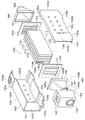
図1及び図2に示されるように、EGRクーラ100は、複数のチューブ110、コアプレート120、水タンク130、入口ガスタンク140、出口ガスタンク160、入口水パイプ170、及び出口水パイプ180を備えている。
As shown in FIGS. 1 and 2, the EGR
図2に示されるように、チューブ110は、排気流路110aを構成する管である。チューブ110は、内燃機関から排出される排気が内部の排気流路110aに流れ、外部に冷却水が流れるようになっている。これにより、チューブ110を介して排気と冷却水とが熱交換される。
As shown in FIG. 2, the
チューブ110は、長手方向に交差する横断面が、扁平な矩形形状を成す細長の管部材として形成されている。各チューブ110は、扁平矩形断面の長辺側となる基本面111が互いに対向するように、一定の間隔を持って配置されている。
The
さらに、チューブ110は、排気流路110aに配置されたフィン110bを有している。フィン110bは、チューブ110の内表面にろう付け接合されている。フィン110bは、排気と冷却水との間での熱交換を促進させるものである。フィン110bは、各チューブ110内に配置されている。
Further, the
コアプレート120は、水タンク130の内部でチューブ110の外側に構成された空間(後述する水タンク内空間130E)と、入口ガスタンク140の内部(後述する排気流路140C)と、を区画する四角形状の板状の部材である。コアプレート120は、入口ガスタンク140側と出口ガスタンク160側との2枚が設けられている。
The
また、コアプレート120は、複数のチューブ110を保持する役割を果たす。このため、コアプレート120は、各チューブ110の長手方向端部が挿通するチューブ孔121を有している。各チューブ110の長手方向端部は、対応するチューブ孔121に通された状態でチューブ孔121にろう付けされている。これにより、入口ガスタンク140の排気流路140Cとチューブ110の排気流路110aとが連通する。
The
水タンク130は、複数のチューブ110及びコアプレート120を内部に収容する筒状の容器体である。図1に示されるように、水タンク130は、第1水タンク130Aと第2水タンク130Bとを備えて構成されている。
The
第1水タンク130Aは、本体部131、上面部132、及び下面部133を有して構成されている。本体部131は、チューブ110の基本面111に対向する部分である。上面部132は、本体部131の上側端部からチューブ110側に略90度に折り曲げられた部分である。下面部133は、本体部131の下側端部からチューブ110側に略90度に折り曲げられた部分である。これにより、第1水タンク130Aは、横断面形状がコの字状を成している。
The
上面部132のうちの出口ガスタンク160側には、外側(上側)に膨出する膨出部132aが形成されている。さらに、膨出部132aの領域内には、バーリング部(縁立て部)が形成されていると共に、出口水パイプ180が接続されるパイプ孔132bが形成されている。また、下面部133の長手方向の両端部には、外側(下側)に膨出する膨出部133a、133bが形成されている。
A bulging
第2水タンク130Bは、本体部134、上面部135、及び下面部136を有して構成されている。本体部134は、チューブ110の基本面111に対向する部分である。上面部135は、本体部134の上側端部からチューブ110側に略90度に折り曲げられた部分である。下面部136は、本体部131の下側端部からチューブ110側に略90度に折り曲げられた部分である。これにより、第2水タンク130Bは、横断面形状が上記第1水タンク130Aよりも浅いコの字状を成している。
The
上面部135の長手方向における流出側開口部113bに対応する側の端部には、第1水タンク130Aと同様に、外側(上側)に膨出する膨出部135aが形成されている。また、下面部136の長手方向の両端部には、第1水タンク130Aと同様に、外側(下側)に膨出する膨出部136a、136bが形成されている。
A bulging
第1水タンク130Aと第2水タンク130Bとは、コの字状断面の開口側が互いに接合されて、断面四角形状を成す筒状の水タンク130を構成している。水タンク130の長手方向の両端部は、外部に開口する開口側端部130C、130Dとなっている。そして、両開口側端部130C、130Dのうち、入口ガスタンク140側となる開口側端部130Cには、水タンク膨出部としての膨出部133cが形成されている。
The
膨出部133cは、四角形状を成す開口側端部130Cの下側の辺の中央部で、この下側の辺よりも外側(下側)に膨出するとともに、膨出部133aに繋がるように形成されている。
The bulging
入口ガスタンク140は、外側に配置された外側ガスタンク140Aと、内側に配置された内側ガスタンク140Bと、を備えた二重構造を成している。入口ガスタンク140は、排気管からの排気を複数のチューブ110に分配供給するための排気流路140Cを構成している。
The
外側ガスタンク140Aは、外形形状が直方体状を成して、チューブ110側となる一方の面が開口する半容器体として形成されている。開口している部位は、開口部141となっている。開口部141は、四角形状を成している。外側ガスタンク140Aは、開口部141とは反対側の他方の面の下方にバーリング部が形成されていると共に、フランジ148の接続用となる円形のフランジ孔142が形成されている。また、外側ガスタンク140Aの上側となる面には、入口水パイプ170の接続用のパイプ孔143が形成されている。
The
さらに、外側ガスタンク140Aの下側となる外側壁部144には、図示しないガスタンク膨出部が形成されている。当該ガスタンク膨出部は、四角形状を成す開口部141の下側の辺の中央部で、この下側の辺よりも外側(下側)に膨出すると共に、フランジ孔142側に向けて順次膨出量が小さくなるように形成されている。ガスタンク膨出部は、外側ガスタンク140Aにおいてパイプ孔143が形成された面に対向する面、すなわちパイプ孔143が形成された面の反対側となる面に設けられている。
Further, a gas tank bulging portion (not shown) is formed on the
内側ガスタンク140Bは、漏斗状を成して内部に排気が流通する排気流路140Cを構成するものである。内側ガスタンク140Bは、チューブ110側となる一方側に形成された四角形状を成す開口部146を有している。また、内側ガスタンク140Bは、他方側にバーリング部が形成されていると共に、フランジ148の接続用となる円形のフランジ孔147が形成されている。
The
内側ガスタンク140Bは、外側ガスタンク140Aの内部に挿入されている。また、フランジ孔147のバーリング部の外周面と、フランジ孔142のバーリング部の内周面と、が互いに接合されている。
The
このように、二重構造に構成された入口ガスタンク140は、内側ガスタンク140Bと外側ガスタンク140Aとの間に図示しない外側空間を備えるタンクとなっている。外側空間は、入口ガスタンク140の外部に繋がっていると共に、ガスタンク膨出部を介して水タンク140の内部空間に繋がっている。
Thus, the
図1に示されるように、入口ガスタンク140には、図示しない排気ガス再循環装置における相手側排気管との接続用のフランジ148が接合されている。フランジ148は、外形が菱形状を成す板部材である。フランジ148は、中心部に形成された連通孔148aと、連通孔148aの隣に形成されたボルト孔148bと、を有している。ボルト孔148bは、ボルトによる締結用の雌ねじである。そして、連通孔148aと、入口ガスタンク140のフランジ孔142、147と、が繋がるようにして、フランジ148は、入口ガスタンク140に接合されている。
As shown in FIG. 1, the
出口ガスタンク160は、漏斗状を成して内部に排気流路を形成するものである。図2に示されるように、出口ガスタンク160は、チューブ110側となる一方側に四角形状を成す開口部161が形成されている。また、出口ガスタンク160は、他方側にバーリング部が形成されているとともに、フランジ163の接続用となる円形のフランジ孔162が形成されている。図1に示されるように、出口ガスタンク160には、排気ガス再循環装置における相手側排気管との接続用のフランジ163が接合されている。
The
フランジ163は、上記のフランジ148と同様に、外形が菱形状を成す板部材である。フランジ163は、中心部に図示しない連通孔が形成されているとともに、連通孔の隣にボルト孔163aが形成されている。当該連通孔と、出口ガスタンク160のフランジ孔162と、が繋がるようにして、フランジ163は、出口ガスタンク160に接合されている。
Like the
そして、出口ガスタンク160の開口部161の内周面は、複数のチューブ110のうちの出口ガスタンク160側のコアプレート120の外周面に接合されている。よって、出口ガスタンク160の内部となる排気流路は、各チューブ110内の排気流路110aに繋がっている。
The inner peripheral surface of the
上記の第1水タンク130A及び第2水タンク130Bは、各チューブ110の外側を覆うように各チューブ110の配列方向に組み付けされている。これにより、各チューブ110は水タンク130の内部に収容される。
The
水タンク130の内部でチューブ110の外側に形成される空間が水タンク内空間130Eになっている。よって、水タンク130の膨出部133a、136aによって形成される空間、膨出部133b、136bによって形成される空間、及び膨出部132a、135aによって形成される空間と、各チューブ110間の空間すなわち水タンク内空間130Eと、が繋がっている。
A space formed outside the
さらに、水タンク130の膨出部133cの内周面が、外側ガスタンク140Aのガスタンク膨出部の外周面に接合され、膨出部133cと当該ガスタンク膨出部とが接続されている。膨出部133cおよび当該ガスタンク膨出部によって冷却水の流路が形成されている。そして、当該流路を介して、水タンク130の膨出部133a、136aによって形成される空間と、入口ガスタンク140の外側空間と、が繋がっている。
Furthermore, the inner peripheral surface of the bulging
入口水パイプ170は、エンジンから流出される冷却水が流入する管部材である。入口水パイプ170の先端部は、外側ガスタンク140Aのパイプ孔143に挿入されて接合されている。入口水パイプ170は、入口ガスタンク140の外側空間と繋がっている。
The
出口水パイプ180は、水タンク内空間130Eを流れた冷却水が流出する管部材である。出口水パイプ180の先端部は、水タンク130の膨出部132aにおけるパイプ孔132bに挿入されて接合されている。出口水パイプ180は、水タンク130の膨出部132a、135aによって形成される空間と繋がっている。以上が、EGRクーラ100の全体構成である。
The
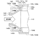
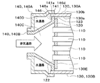
次に、水タンク130及びコアプレート120に対する入口ガスタンク140の接合構造について説明する。まず、図3に示されるように、内側ガスタンク140Bの開口部146において、水タンク130側の開口端部146aが平板状に構成されている。開口端部146aの外形のサイズは、入口ガスタンク140側のコアプレート120のうちの内側ガスタンク140B側の平坦面122の外形のサイズよりも小さくなっている。
Next, the joint structure of the
そして、内側ガスタンク140Bの開口端部146aの全体が、コアプレート120の平坦面122に接合されている。上記のサイズの関係から、内側ガスタンク140Bの開口端部146aがコアプレート120の平坦面122の範囲内に接合されている。これにより、内側ガスタンク140Bの排気流路140Cは、各チューブ110内の排気流路110aに繋がっている。
The entire
また、内側ガスタンク140Bのフランジ孔147が外側ガスタンク140Aのフランジ孔142に接合されている。したがって、内側ガスタンク140Bがろう付けされた部分は、コアプレート120の平坦面122に対するろう付け部146bと、外側ガスタンク140Aのフランジ孔142に対するろう付け部146cと、の2カ所である。
Further, the
本実施形態では、コアプレート120の外周部123が、外側ガスタンク140Aのうちの水タンク130側の開口部141の内壁面141aに接合されている。これにより、外側ガスタンク140A、内側ガスタンク140B、及びコアプレート120によって冷却水の通路となる外側空間140Dが構成されている。
In this embodiment, the outer
さらに、水タンク130の開口側端部130Cの内壁面130aは、外側ガスタンク140Aの開口部141の外壁面141bに接合されている。これにより、入口ガスタンク140の外側空間140Dは、外側ガスタンク140Aの下側に設けられた図示しないガスタンク膨出部を介して水タンク内空間130Eに繋がっている。
Furthermore, the
一方、図2に示された水タンク130の開口側端部130Dの内壁面は、出口ガスタンク160の開口部161の外壁面に接合されている。したがって、水タンク内空間130Eを流通する冷却流体と、ガスタンク140によってチューブ110の内部に供給される排気との間で熱交換が行われる。
On the other hand, the inner wall surface of the opening
以上説明したように、本実施形態では、内側ガスタンク140Bの開口端部146aがコアプレート120の平坦面122に接合されているので、内側ガスタンク140Bがコアプレート120と外側ガスタンク140Aによって挟まれない構造になっている。このため、内側ガスタンク140Bの寸法をコアプレート120と外側ガスタンク140Aとの両方に合わせる必要がない。したがって、内側ガスタンク140Bの寸法精度を低減することができる。
As described above, in the present embodiment, since the opening
このように、内側ガスタンク140Bの寸法精度が不要になるので、内側ガスタンク140Bの開口部146の形状が複雑にならずに済む。したがって、内側ガスタンク140Bを形成するための加工工程数を減らすことができると共に、内側ガスタンク140Bを形成するための成形型の寿命の低下を抑制することができる。
Thus, since the dimensional accuracy of the
また、内側ガスタンク140Bがコアプレート120と外側ガスタンク140Aによって挟まれないので、内側ガスタンク140Bの開口端部146aにおけるろう付け部分はコアプレートの平坦面122に対する部分のみである。したがって、内側ガスタンク140Bの開口部146の接合に必要となるろう材量を低減することができる。
Further, since the
(第2実施形態)
本実施形態では、第1実施形態と異なる部分について説明する。図4に示されるように、EGRクーラ100には第1実施形態とは異なる形状のチューブ110が採用されている。本実施形態では、チューブ110の長手方向端部がコアプレート120の平坦面122と同一平面に位置するように、チューブ110とコアプレート120とが接合されている。このように、チューブ110の形状が第1実施形態と異なっていても良い。
(Second Embodiment)
In the present embodiment, parts different from the first embodiment will be described. As shown in FIG. 4, the
(第3実施形態)
本実施形態では、第1、第2実施形態と異なる部分について説明する。図5に示されるように、EGRクーラ100には第1実施形態とは異なる形状のチューブ110が採用されている。具体的には、各チューブ110の基本面111には凸部112が設けられている。
(Third embodiment)
In the present embodiment, parts different from the first and second embodiments will be described. As shown in FIG. 5, the
凸部112は、基本面111の表面から外方に向けて突出するようにプレス加工された打出し部であり、基本面111の外周部に堰のように形成されている。そして、各チューブ110は、基本面111に形成された凸部112が互いに当接するように複数積層されて、各凸部112同士が接合されている。
The
したがって、コアプレート120に設けられるチューブ孔121は、各凸部112同士が接合された複数のチューブ110が一体的に通される1つのチューブ孔121で済む。
Therefore, the
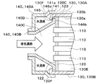
(第4実施形態)
本実施形態では、第1〜第3実施形態と異なる部分について説明する。図6に示されるように、本実施形態では、コアプレート120の外周部123が、水タンク130の開口側端部130Cの内壁面130aに接合されている。そして、外側ガスタンク140Aの開口部141の内壁面141aが、水タンク130の外壁面130bに接合されている。このように、コアプレート120は水タンク130に接合されていても良い。
(Fourth embodiment)
In the present embodiment, parts different from the first to third embodiments will be described. As shown in FIG. 6, in this embodiment, the outer
(第5実施形態)
本実施形態では、第4実施形態と異なる部分について説明する。図7に示されるように、本実施形態では、水タンク130は、開口側端部130Cにかしめ部130Fを有している。かしめ部130Fは、水タンク130の開口側端部130Cがコアプレート120側に押し曲げられて内側ガスタンク140Bの開口端部146aにかしめ固定された部分である。
(Fifth embodiment)
In the present embodiment, parts different from the fourth embodiment will be described. As shown in FIG. 7, in this embodiment, the
これにより、内側ガスタンク140Bの開口端部146aがコアプレート120と水タンク130の開口側端部130Cとに挟まれた構造になる。水タンク130をこのような形状としても良い。
As a result, the opening
(第6実施形態)
本実施形態では、第1〜第5実施形態と異なる部分について説明する。図8に示されるように、本実施形態では、内側ガスタンク140Bの開口端部146aの外形のサイズは、入口ガスタンク140側のコアプレート120のうちの内側ガスタンク140B側の平坦面122の外形のサイズよりも大きくなっている。
(Sixth embodiment)
In the present embodiment, parts different from the first to fifth embodiments will be described. As shown in FIG. 8, in this embodiment, the size of the
そして、内側ガスタンク140Bの開口端部146aの全体が、コアプレート120の平坦面122に接合されている。上記のサイズの関係から、内側ガスタンク140Bの開口端部146aがコアプレート120の外周部123から突出している。言い換えると、コアプレート120の平坦面122が内側ガスタンク140Bの開口端部146aの範囲内に接合されている。
The entire
また、内側ガスタンク140Bの開口端部146aの外周部146dが、外側ガスタンク140Aの内壁面141aに接合されている。したがって、外側ガスタンク140Aの内壁面141aに接合された部材がコアプレート120ではなく内側ガスタンク140Bの開口端部146aであることが、図3に示された構成と異なる。このように、内側ガスタンク140Bが外側ガスタンク140Aに接合されていても良い。
Further, the outer
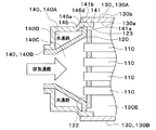
(第7実施形態)
本実施形態では、第6実施形態と異なる部分について説明する。図9に示されるように、本実施形態では、内側ガスタンク140Bの開口端部146aの外周部146dが、水タンク130の開口側端部130Cの内壁面130aに接合されている。そして、外側ガスタンク140Aの開口部141の内壁面141aが、水タンク130の外壁面130bに接合されている。このように、内側ガスタンク140Bは水タンク130に接合されていても良い。
(Seventh embodiment)
In the present embodiment, parts different from the sixth embodiment will be described. As shown in FIG. 9, in this embodiment, the outer
(他の実施形態)
上記各実施形態で示されたEGRクーラ100の構成は一例であり、上記で示した構成に限定されることなく、本発明を実現できる他の構成とすることもできる。例えば、排気熱交換装置をEGRクーラ100に適用したものとして説明したが、これに限定されることなく、他の熱交換器へも広く適用可能である。例えば、外気に排出される排気ガスと冷却水との間で熱交換して、冷却水を加熱する排熱回収熱交換器に適用しても良い。
(Other embodiments)
The configuration of the EGR cooler 100 shown in each of the above embodiments is merely an example, and is not limited to the configuration described above, and may be another configuration that can realize the present invention. For example, although the exhaust heat exchange device has been described as being applied to the
120 コアプレート
122 平坦面
140B 内側ガスタンク
130 水タンク
130E 水タンク内空間
130a 内壁面
140 ガスタンク
141 開口部
141a 内壁面
146a 開口端部
120
Claims (2)
前記チューブを内部に収容する筒状の水タンク(130)と、
外側に配置された外側ガスタンク(140A)と、内側に配置された内側ガスタンク(140B)と、を有し、前記内側ガスタンク内に前記排気が流通する排気流路(140C)を構成する二重構造のガスタンク(140)と、
前記水タンクの内部で前記チューブの外側に構成された水タンク内空間(130E)と、前記排気流路と、を区画する板状に構成されており、前記チューブの長手方向端部が挿通していることにより、前記排気流路と前記チューブの内部とを連通させるコアプレート(120)と、
を備え、
前記水タンク内空間を流通する冷却流体と、前記ガスタンクによって前記チューブの内部に供給される排気との間で熱交換する排気熱交換装置であって、
前記内側ガスタンクは、前記水タンク側の開口端部(146a)の全体が前記コアプレートのうちの前記内側ガスタンク側の平坦面(122)に接合されており、
前記コアプレート及び前記内側ガスタンクのうちのいずれか一方が、前記水タンクの内壁面(130a)または前記外側ガスタンクのうちの前記水タンク側の開口部(141)の内壁面(141a)に接合されている排気熱交換装置。 A tube (110) through which exhaust gas discharged from the internal combustion engine flows;
A cylindrical water tank (130) for accommodating the tube therein;
A dual structure having an outer gas tank (140A) disposed on the outer side and an inner gas tank (140B) disposed on the inner side, and constituting an exhaust passage (140C) through which the exhaust flows in the inner gas tank Gas tank (140),
It is configured in a plate shape that divides the water tank inner space (130E) configured outside the tube inside the water tank and the exhaust flow path, and the longitudinal end portion of the tube is inserted therethrough. A core plate (120) for communicating the exhaust passage and the inside of the tube;
With
An exhaust heat exchange device for exchanging heat between the cooling fluid flowing through the space in the water tank and the exhaust gas supplied to the inside of the tube by the gas tank,
In the inner gas tank, the entire open end (146a) on the water tank side is joined to the flat surface (122) on the inner gas tank side of the core plate,
One of the core plate and the inner gas tank is joined to the inner wall surface (141a) of the inner wall surface (130a) of the water tank or the opening (141) on the water tank side of the outer gas tank. Exhaust heat exchange device.
前記水タンクは、前記ガスタンク側の開口側端部(130C)が前記内側ガスタンクの前記開口端部にかしめ固定されたかしめ部(130F)を有している請求項1に記載の排気熱交換装置。 The core plate is joined to the inner wall surface (130a) of the water tank,
The exhaust heat exchanger according to claim 1, wherein the water tank has a caulking portion (130F) in which an opening end portion (130C) on the gas tank side is caulked and fixed to the opening end portion of the inner gas tank. .
Priority Applications (1)
| Application Number | Priority Date | Filing Date | Title |
|---|---|---|---|
| JP2016074908A JP2017187196A (en) | 2016-04-04 | 2016-04-04 | Exhaust heat exchanger |
Applications Claiming Priority (1)
| Application Number | Priority Date | Filing Date | Title |
|---|---|---|---|
| JP2016074908A JP2017187196A (en) | 2016-04-04 | 2016-04-04 | Exhaust heat exchanger |
Publications (1)
| Publication Number | Publication Date |
|---|---|
| JP2017187196A true JP2017187196A (en) | 2017-10-12 |
Family
ID=60043988
Family Applications (1)
| Application Number | Title | Priority Date | Filing Date |
|---|---|---|---|
| JP2016074908A Pending JP2017187196A (en) | 2016-04-04 | 2016-04-04 | Exhaust heat exchanger |
Country Status (1)
| Country | Link |
|---|---|
| JP (1) | JP2017187196A (en) |
Cited By (1)
| Publication number | Priority date | Publication date | Assignee | Title |
|---|---|---|---|---|
| WO2019131569A1 (en) * | 2017-12-27 | 2019-07-04 | 株式会社ティラド | Header plateless type heat exchanger |
-
2016
- 2016-04-04 JP JP2016074908A patent/JP2017187196A/en active Pending
Cited By (3)
| Publication number | Priority date | Publication date | Assignee | Title |
|---|---|---|---|---|
| WO2019131569A1 (en) * | 2017-12-27 | 2019-07-04 | 株式会社ティラド | Header plateless type heat exchanger |
| JPWO2019131569A1 (en) * | 2017-12-27 | 2020-12-10 | 株式会社ティラド | Header plateless heat exchanger |
| JP7244439B2 (en) | 2017-12-27 | 2023-03-22 | 株式会社ティラド | Header plateless heat exchanger |
Similar Documents
| Publication | Publication Date | Title |
|---|---|---|
| EP2581696B1 (en) | Heat exchanger and partition thereof | |
| US10240872B2 (en) | Indirect charge-air cooler | |
| US20070193732A1 (en) | Heat exchanger | |
| JP5278020B2 (en) | EGR gas cooling device | |
| JP2015025649A (en) | Heat exchanger | |
| JP7218354B2 (en) | Header plateless heat exchanger | |
| JP2017172864A (en) | Passage structure | |
| JP2019207097A (en) | Heat exchanger | |
| JP2006342997A (en) | Heat exchanger | |
| JP2014169857A (en) | Exhaust heat transfer equipment | |
| JP2017187196A (en) | Exhaust heat exchanger | |
| JP2009216151A (en) | Sealing structure and heat exchanger using the same | |
| JP2014081175A (en) | Casing connection structure of exhaust heat exchanger | |
| EP3495761A1 (en) | Heat exchange device | |
| CN108627035A (en) | Heat-exchanging component and heat-exchange system | |
| JP2015206507A (en) | heat exchanger | |
| JP2021134926A (en) | Laminate-type heat exchanger | |
| JP2016183833A (en) | Header plate-less heat exchanger | |
| JP2004169953A (en) | Duplex heat exchanger | |
| CN218329487U (en) | Heat exchanger | |
| JP2006017442A (en) | Heat exchanger | |
| JP2019190674A (en) | Heat exchanger | |
| CN112432537B (en) | Heat exchanger and method for manufacturing the same | |
| JP7456801B2 (en) | Laminated heat exchanger | |
| JP7121551B2 (en) | Heat exchanger |