JP2017186751A - Architectural structure - Google Patents
Architectural structure Download PDFInfo
- Publication number
- JP2017186751A JP2017186751A JP2016074532A JP2016074532A JP2017186751A JP 2017186751 A JP2017186751 A JP 2017186751A JP 2016074532 A JP2016074532 A JP 2016074532A JP 2016074532 A JP2016074532 A JP 2016074532A JP 2017186751 A JP2017186751 A JP 2017186751A
- Authority
- JP
- Japan
- Prior art keywords
- door
- indoor space
- low
- space
- opening
- Prior art date
- Legal status (The legal status is an assumption and is not a legal conclusion. Google has not performed a legal analysis and makes no representation as to the accuracy of the status listed.)
- Granted
Links
Images


Abstract
Description
本発明は、室の壁に設けられた出入り用の開口と、その開口に開閉可能に設けられた扉と、が備えられている建築物に関する。 The present invention relates to a building provided with an opening for entering and exiting provided in a wall of a room and a door provided in the opening so as to be openable and closable.
集中豪雨や台風等の水害時に、扉を挟んだ室外空間側の水位が高くなった場合、その水圧が扉に作用する。それに伴って、ラッチ等の止め金具がストライクに押し付けられて、スライドさせることができなかったり、又は、扉に作用する水圧の影響で、扉を開けることが困難となる虞がある。 When the water level on the outdoor space side across the door becomes high during flood damage such as heavy rain or typhoon, the water pressure acts on the door. Along with this, there is a possibility that a stopper such as a latch is pressed against the strike and cannot be slid, or it may be difficult to open the door due to the influence of water pressure acting on the door.
従来、この種の建築物としては、上述のような水害によって扉を開けられなくなる緊急時に、室から脱出できるように構成された扉を備えたものがあった(例えば、特許文献1参照)。
具体的には、扉に対して、一般的に浸水し易い深度より上(扉の上半部)に、内開きの補助扉を備え、緊急時には、補助扉を開けてその補助開口を乗り越えて室外空間側へ脱出できるように構成されたものであった。
補助扉に関しては、止め金具で扉に対してロックできるように構成されている。
Conventionally, this type of building includes a door configured to be able to escape from a room in an emergency where the door cannot be opened due to water damage as described above (see, for example, Patent Document 1).
Specifically, the door is provided with an inwardly opening auxiliary door above the depth that is generally easily submerged (the upper half of the door), and in an emergency, the auxiliary door is opened and the auxiliary opening is overcome. It was configured to be able to escape to the outdoor space side.
The auxiliary door is configured so that it can be locked to the door with a stopper.
上述した従来の建築物によれば、扉が水圧で開かない時でも、止め金具のロックを解除して補助扉を開き、例えば、踏み台等を利用して補助開口までよじ登って通り抜け、室外側へ降り立つことで脱出することができる。
しかしながら、扉の上半部にある補助開口までよじ登ったり、そこから室外側へ降り立つ行為には、筋力が必要であり、ましてや、水害の環境下においては、足元が見え難く且つ滑り易いから、この補助扉は、運動能力の低い人には利用し難いものとなる。
According to the above-mentioned conventional building, even when the door does not open due to water pressure, the stopper is unlocked and the auxiliary door is opened. For example, the door is climbed up to the auxiliary opening using a stepping platform, etc. You can escape by getting off.
However, muscular strength is required to climb up to the auxiliary opening in the upper half of the door and to descend to the outside of the door, and even in a flooded environment, it is difficult to see your feet and slip easily. Auxiliary doors are difficult to use for people with low motor skills.
また、水位が、補助扉に達するような場合には、当然のことながら補助扉に水圧が作用することになるから、その水圧の作用で、止め金具が外れなくなって、結果的には、補助扉が開かなくなる虞もある。 In addition, when the water level reaches the auxiliary door, the water pressure acts on the auxiliary door as a matter of course, so that the stopper cannot be removed by the action of the water pressure. There is also a risk that the door will not open.
従って、本発明の目的は、上記問題点を解消し、扉に水圧が作用しても開けることができ、扉で塞いでいた開口から脱出できる建築物を提供するところにある。 Accordingly, an object of the present invention is to provide a building that solves the above problems and can be opened even when water pressure is applied to the door, and can escape from the opening that was closed by the door.
本発明の特徴は、室の壁に設けられた出入り用の開口と、
前記開口に開閉可能に設けられた扉と、が備えられ、
前記扉、及び、前記壁のうち前記扉に隣接する隣接壁部の少なくとも何れか一方において、前記扉の下部の高さに相当する部分に、破壊可能な低強度部が備えられ、
前記低強度部は、非破壊状態では室内空間と室外空間とを非連通状態に区画し、かつ、破壊状態では前記室内空間と前記室外空間とを連通させるところにある。
A feature of the present invention is an opening for entering and exiting provided on the wall of the chamber,
A door provided in the opening so as to be openable and closable,
In at least one of the door and the adjacent wall portion adjacent to the door among the walls, a portion corresponding to the height of the lower portion of the door is provided with a breakable low-strength portion,
The low-strength portion divides the indoor space and the outdoor space in a non-communication state in a non-destructive state, and communicates the indoor space and the outdoor space in a destructive state.
本発明によれば、前記扉、及び、前記隣接壁部の少なくとも何れか一方において、前記扉の下部の高さに相当する部分に、破壊可能な低強度部が備えられているから、この低強度部を非破壊状態に保っていれば、扉としての遮断性を確保することができ、室内空間と室外空間とを非連通状態に区画することができる。また、低強度部を破壊することで、室内空間と室外空間とを連通させることができる。 According to the present invention, at least one of the door and the adjacent wall portion is provided with a breakable low-strength portion at a portion corresponding to the height of the lower portion of the door. If the strength portion is kept in a non-destructive state, the blocking property as a door can be secured, and the indoor space and the outdoor space can be partitioned in a non-communication state. Moreover, indoor space and outdoor space can be connected by destroying a low intensity | strength part.
よって、日常的には、低強度部を非破壊状態に保っておくことで、扉としての遮断性能を発揮できながら、水害等で扉に水圧が作用するような場合には、低強度部を破壊することで、室内空間と室外空間とを連通状態にできる。
従って、室内空間と室外空間とが連通することで水が流通して互いの水位が平衡状態になれば、扉の内外での水圧差が無くなる(又は緩和される)から、扉を開くことが可能となる。
このように、扉が開けば、従来のように、扉の高い位置にある補助開口を乗り越えたりせずに歩いて脱出できるから、運動能力の低い人でも容易に利用できるようになる。
Therefore, on a daily basis, keeping the low-strength part in a non-destructive state can exhibit the blocking performance as a door, but if the water pressure acts on the door due to water damage etc., the low-strength part is By destroying, the indoor space and the outdoor space can be in communication.
Therefore, when the indoor space and the outdoor space communicate with each other and water flows and the water levels are in an equilibrium state, the water pressure difference between the inside and outside of the door disappears (or is mitigated), and the door can be opened. It becomes possible.
In this way, when the door is opened, it is possible to escape by walking without getting over the auxiliary opening at a high position of the door as in the prior art, so that even a person with low exercise ability can easily use it.
本発明においては、前記室内空間のうち平面視で前記扉と前記低強度部とを含む扉近接領域を、前記室内空間の他の領域と仕切ることが可能な区画部が設けられていると好適である。 In the present invention, it is preferable that a partition portion capable of partitioning a door proximity region including the door and the low-strength portion in plan view in the indoor space from other regions of the indoor space is provided. It is.
本構成によれば、区画部を設けてあることで、破壊状態にした低強度部から室内空間へ浸入した水を、扉近接領域に溜めて、室外空間の水位と平衡にすることができる。
その際、室内空間の全域に比べて狭い扉近接領域に絞って水を溜めることができるから、扉近接領域での水位上昇を速め、扉の内外での水圧を早急に平衡状態にすることが可能となる。
その結果、扉を開けられるようになるまでの時間短縮を図れ、迅速な脱出が可能となる。
According to this configuration, since the partition portion is provided, the water that has entered the indoor space from the low-strength portion that has been destroyed can be stored in the door proximity region and balanced with the water level in the outdoor space.
At that time, water can be collected by narrowing the area close to the door compared to the whole area of the indoor space, so that the water level rises quickly in the area close to the door, and the water pressure inside and outside the door can be quickly balanced. It becomes possible.
As a result, it is possible to shorten the time until the door can be opened and to quickly escape.
本発明においては、前記室内空間のうち前記扉に近い箇所と前記室外空間とを連通可能な連通路と、
前記連通路を、連通状態と非連通状態とに切り換え可能な切換装置と、が備えられていると好適である。
In the present invention, a communication path capable of communicating the location close to the door and the outdoor space in the indoor space,
It is preferable that a switching device capable of switching the communication path between a communication state and a non-communication state is provided.
本構成によれば、切換装置によって連通路を非連通状態から連通状態に切り換えることで、扉に近い個所において室内空間と室外空間とを連通させることが可能となる。
従って、例えば、前記低強度部を破壊状態にして水位の平衡を図る際に、平衡に至るまでの時間を、より短縮化したり、低強度部の破壊操作が捗らない時には、その代替えの役割で水位の平衡を図ることが可能となる。
According to this configuration, by switching the communication path from the non-communication state to the communication state by the switching device, the indoor space and the outdoor space can be communicated at a location close to the door.
Therefore, for example, when the low-strength part is in a broken state and the water level is balanced, the time to reach the equilibrium is further shortened, or when the destruction operation of the low-strength part does not progress, The water level can be balanced.
本発明においては、破壊不能であると共に防火性能を有するカバー部材が、前記低強度部の室内側に、開閉自在な状態で備えられていると好適である。 In the present invention, it is preferable that a cover member that is indestructible and has fire prevention performance is provided on the indoor side of the low-strength portion so as to be freely opened and closed.
本構成によれば、カバー部材を設けてあるから、室外側から、人為的に低強度部を破壊されても、カバー部材までは破壊できず、日常的な防犯性能を維持することが可能となる。
また、カバー部材は防火性能を発揮できるから、カバー部材を閉状態に保っていることで、扉としての防火性能を維持することができる。
According to this configuration, since the cover member is provided, even if the low-strength portion is artificially destroyed from the outdoor side, the cover member cannot be destroyed, and daily crime prevention performance can be maintained. Become.
Moreover, since the cover member can exhibit fireproof performance, the fireproof performance as a door can be maintained by keeping the cover member closed.
更には、カバー部材は、低強度部の室内側に開閉自在な状態で備えられているから、水害に伴って扉に水圧が作用するような場合、その水圧は、カバー部材より室外側に位置している低強度部によって受けることができ、水圧の影響がカバー部材に及ばない状態で室内側から開操作することができる。従って、水圧でカバー部材が開かないといった問題が発生せず、より確実に、低強度部の破壊操作に移行することができる。 Furthermore, since the cover member is provided on the indoor side of the low-strength part so that it can be opened and closed, when water pressure acts on the door due to water damage, the water pressure is located on the outdoor side of the cover member. Can be received by the low-strength portion, and can be opened from the indoor side in a state where the influence of the water pressure does not reach the cover member. Therefore, the problem that the cover member does not open due to water pressure does not occur, and it is possible to shift to the destruction operation of the low-strength portion more reliably.
以下に本発明の実施の形態を図面に基づいて説明する。
図1、図2は、本発明の建築物の一実施形態である建築物の地下通路2に面した室1を示している。
尚、ここで説明する建築物は、例えば、鉄筋コンクリート等の構造を例に挙げて説明しているが、他の構造であってもよく、特に、限定されるものではない。
Embodiments of the present invention will be described below with reference to the drawings.
1 and 2 show a
In addition, although the building demonstrated here has demonstrated and demonstrated the structure, such as reinforced concrete, for example, another structure may be sufficient and it does not specifically limit.
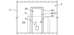
室1は、壁3で囲まれており、地下通路2に面する壁3には、出入り用の開口3Aが形成してある。
開口3Aには、開閉可能に設けられた金属製の扉4が備えられている。
The
The
地下通路2は、図には示さないが、地上の外部空間に連通しており、例えば、建築物に備えられた排水設備の排水能力を超えるような水害が発生した場合、浸水する虞がある。
地下通路2が浸水すると、浸水深さに相当する水圧が扉4に作用するから(図4参照)、水圧が大きくなればなるほど、開閉操作が困難となる。当該発明に係る建築物は、この様な状況下においても、扉4を開けて室1から脱出できるように構成されている。
Although the
When the
前記扉4は、当該実施形態においては、外開きの片開き扉を例に挙げて説明している。
扉4は、図3に示すように、壁3に固定された矩形形状の扉枠4Aと、扉枠4Aの左右の一対の縦枠部の内の一方の縦枠部に蝶番を介して縦軸心周りに揺動自在に取り付けられた扉本体4Bと、を備えて構成してある。
扉枠4Aに対する扉本体4Bの揺動及び固定操作は、扉本体4Bの上下中央部に備えられたドアノブやラッチ等の開閉機構4Cによって実施できる。
In the embodiment, the
As shown in FIG. 3, the
The swinging and fixing operation of the door
上述のように、扉4が、浸水による水圧を受けると、当該実施形態のように、外開きの扉の場合は、扉本体4Bの外面に作用した水圧が扉本体4Bの外縁部から扉枠4Aに伝わり、ラッチを解除できても水圧による押圧力の作用で、扉本体4Bを室外空間Vo側へ押し開くことが困難となる。また、参考例として、内開きの扉の場合は、ラッチと扉枠4Aとの当接部分に、水圧による押圧力が集中的に作用し、ラッチの解除操作が困難となって扉本体4Bを室内空間Vi側へ開操作することが困難となる。このように、水圧の影響は、外開きや内開きの何れの形式の扉4においても開閉が困難となる現象となって現れる。
As described above, when the
また、扉本体4Bにおける開閉機構4Cより下方の下半領域(扉の下部の高さに相当する部分)Kには、図2、図3に示すように、室内空間Viと室外空間Voとを連通可能な矩形形状の窓部5が形成してある。
前記窓部5には、扉厚み内における室外空間Vo側に、板状の強化ガラス(低強度部の一例)6が嵌め殺し状態に設けられている。また、窓部5の扉厚み内における前記強化ガラス6より室内空間Vi側には、内開きタイプの金属製カバー部材7が開閉自在な状態に設けられている。扉全体としては、窓部5を金属製のカバー部材7で閉塞できるから、防火扉を構成することができる。
Further, in the lower half region (a portion corresponding to the height of the lower part of the door) K below the opening / closing mechanism 4C in the door
The
窓部5の強化ガラス6は、金属製の扉本体4Bよりも低強度であり、設置状態(非破壊状態)では、室内空間Viと室外空間Voとを非連通状態に区画している。また、強化ガラス6は、例えば、ハンマー等によって打撃されると、容易に破壊するように形成されている。即ち、強化ガラス6は、面全体で均一な水圧には耐えるが、一点に集中した衝撃等が作用すると破壊するように構成されている。従って、カバー部材7を開いた状態で強化ガラス6を破壊すると、室内空間Viと室外空間Voとを連通させることができる(図5参照)。
The tempered
尚、強化ガラス6は、室外空間Vo側からでも、室内空間Vi側からでも破壊操作を行えるが、カバー部材7の開操作は、室内空間Vi側からのみ実施できるように止め金具7aをカバー部材7の室内側に臨ませて施錠できるように設けられている。
従って、日常的には、第三者が、室外空間Vo側から窓部5を破壊して扉4のロック解除を行うといった侵入行為を阻止することができながら、前記水害等の場合には、室内空間Vi側から、カバー部材7を開操作すると共に、強化ガラス6を破壊操作して、室外空間Voの水を、窓部5を通して室内空間Viへ流入させることが可能となる(図5、図6参照)。
The tempered
Therefore, on a daily basis, while a third party can prevent an intruding action such as breaking the
因みに、ハンマー等、強化ガラス6を破壊させる破壊道具は、開口3Aの近傍に常備してある事が好ましい。例えば、カバー部材7の背面に破壊道具を着脱自在に設けてあれば、カバー部材7が閉状態となっている普段においては、室内側から見えないから美観性を損ねることが無く、使用する時には、カバー部材7を開けばすぐに使用でき、紛失することもなく好適である。勿論、破壊道具の設置個所は、これに限るものではない。
Incidentally, it is preferable that a breaking tool such as a hammer for breaking the tempered
強化ガラス6の破壊によって室内空間Viの水位が上昇すれば、扉4の室内外面に作用する水圧差が減少するから、扉を小さい力で開くことが可能となり、扉4を通して室外へ脱出し易くなる。
尚、前記強化ガラス6は、透明のものを使用すれば、水害時の浸水状況を、室内空間Vi側から強化ガラス6を通して目視確認することができる。
If the water level of the indoor space Vi rises due to the breakage of the tempered
In addition, if the said tempered
次に、室1について開口3A近傍の状況について説明する。
室1には、図1、図2に示すように、区画部8が設けられ、平面視で、扉4とその近傍範囲を含む扉近接領域1Aと、室内空間Viの他の領域1Bとを仕切ることができるように構成されている。当該実施形態においては、扉近接領域1Aと、他の領域1Bとは、同一レベル(又は、ほぼ同一レベル)に形成されている。
区画部8は、一例としては、成人男性の首の位置まで立上った仕切り壁として構成してある。そして、区画部8の一部には、扉近接領域1Aと他の領域1Bとに行き来自在な区画扉8Aが開状態と閉状態とに切替自在に設けられている。
Next, the situation in the vicinity of the
As shown in FIG. 1 and FIG. 2, the
The
上述の浸水に伴って、強化ガラス6を破壊して、窓部5から外部の水を室内に流入させる時、区画扉8Aを閉めておくことで、扉近接領域1Aが小さな水溜め室となり、迅速に室内側の水位を上昇させることができる。
従って、室1の全域に水を流入させるのに比べて、扉内外の水位差を短時間で減少させることができ、その結果、浸水してから早期の内に扉4を開けられるようになり、迅速な脱出が可能となる。
When the tempered
Therefore, compared with the case where water flows into the entire area of the
尚、区画部8は、常設に限るものではなく、例えば、組立式にして、浸水に対応する時に設営して区画部8として利用することも可能である。そうすることで、日常的には、室内を広く利用でき、浸水時には、上述のような作用効果を発揮できるようになる。
In addition, the
〔実施例〕
因みに、扉4における低強度部となる強化ガラス6を設けてある窓部5の位置は、室外空間Voでの浸水を室内空間Vi側に流入させ易いという観点からは、扉4の下半領域(扉4の下部の高さに相当する部分)であることが好ましい。
また、窓部5の下端部の位置は、扉4の下端部から40cm以下が好ましく、更には、30cm以下がより好ましい。
これらの数値は、京都大学防災研究所年報(第48号B 平成17年4月)の『実物大階段およびドア模型を用いた地下空間からの避難に関する水理実験』に記載された実験データによる値を参考にするもので、該当文献には、「避難限界となるドア前面水深」として、男性で0.4m、女性で0.3mが、ドアを押し開けることができる限界であったことが示されている。
〔Example〕
Incidentally, the position of the
Further, the position of the lower end portion of the
These figures are based on experimental data described in the Kyoto University Disaster Prevention Research Institute Annual Report (No. 48B, April 2005) “Hydraulic Experiments on Evacuation from Underground Space Using Full-Scale Stairs and Door Models” The value is used as a reference. In the relevant literature, the depth of the front of the door, which is the evacuation limit, was 0.4 m for men and 0.3 m for women, which was the limit that could push the door open. It is shown.
〔別実施形態〕
以下に他の実施の形態を説明する。
[Another embodiment]
Other embodiments will be described below.
〈1〉 前記室1は、先の実施形態で説明した地下の一室に限るものではなく、例えば、地上に設けられているものであってもよい。また、用途は、特に限られるものではない。
また、前記室外空間Voは、地下通路に限るものではなく、廊下や、階段や、道路や、隣室等であってもよい。
<1> The
The outdoor space Vo is not limited to the underground passage, and may be a corridor, a staircase, a road, an adjacent room, or the like.
〈2〉 前記扉4は、先の実施形態で説明した外開きの扉に限るものではなく、例えば、内開きの扉であってもよい。また、片開き扉に限るものではなく、例えば、両開き扉や、引戸や、折戸等であってもよく、それらを総称して扉という。
<2> The
〈3〉 前記低強度部6は、先の実施形態で説明した強化ガラス製に限るものではなく、例えば、合成樹脂製や木製や高強度紙製等であってもよい。要するに、人為的に破壊が可能で、非破壊状態では、室内空間Viと室外空間Voとを非連通状態に区画し、破壊状態では両空間を連通させるものであればよく、それらを総称して低強度部という。
因みに、人為的に破壊が可能な例としては、先の実施形態で説明したハンマー等の破壊道具によって破壊することに限らず、例えば、低強度部6の面材の表面に突出する状態で一体に形成されたピン状突起を備え、このピン状突起を基端部周りに揺動させたり、又は、低強度部6の厚み方向に沿ってピン状突起を押し込むことで、低強度部6におけるピン状突起取付部に応力集中を起こさせ、その応力集中によって低強度部を破壊させるものであってもよい。
また、低強度部6の形状は、先の実施形態で説明した矩形形状に限るものではなく、適宜、変更が可能である。
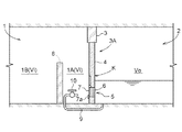
また、低強度部6は、扉4に設けることに替えて、例えば、図7に示すように、壁3のうち扉4に隣接する隣接壁部3Bに設けたものであってもよい。更には、扉4にも合わせて低強度部6を設けるものであってもよい。
但し、隣接壁部3Bに低強度部6を設ける場合で、且つ、前記区画部8を設ける場合は、低強度部6を通して室内空間Viに流入する水を、区画部8に誘導する為に、区画部8内の扉近接領域1Aに面する隣接壁部3Bに形成する必要がある。区画部8を設けない場合には、この限りではない。
<3> The low-
Incidentally, an example that can be artificially destroyed is not limited to destruction by a destruction tool such as a hammer described in the previous embodiment. For example, it is integrally formed in a state of protruding on the surface of the face material of the low-
Further, the shape of the low-
Moreover, it replaces with providing in the
However, when the
〈4〉 前記カバー部材7は、先の実施形態で説明した形状や構造に限るものではなく、適宜、変更が可能である。また、扉4に設けることに限らず、上述のように、低強度部6を隣接壁部3Bに設ける場合には、カバー部材7も、隣接壁部3Bにおいて、低強度部6の室内側に重なる位置に設けることができる。
また、カバー部材7の構造は、カバー部材7の上縁部に沿った揺動軸芯周りに揺動自在な構造や、カバー部材7の下縁部に沿った揺動軸芯周りに揺動自在な構造や、カバー部材7の側縁部に沿った揺動軸芯周りに揺動自在な構造や、カバー部材7のカバー面に沿ってスライド自在な構造や、カバー部材7を対象部に対して着脱自在に取り付ける構造であってもよい。
また、カバー部材7そのものを省略することも可能である。
<4> The
Further, the structure of the
Further, the
〈5〉 室外空間Voの浸水を、室内空間Viに流通させる構造として、図8に示すように、室内空間Viのうち扉4に近い箇所と室外空間Voとを連通可能な連通管(連通路に相当)9と、連通管9を連通状態と非連通状態とに切り換え可能なバルブ(切換装置に相当)10と、を備えることも可能である。
この実施形態によれば、連通管9は、扉4の下部の高さより低い位置に設けられている。バルブ10を閉状態に操作しておくことで、室内空間Viと室外空間Voとは非連通状態を維持でき、水を流通させたい場合には、バルブ10を開操作すればよい。連通管9を通した水の流入を実施することで、前記低強度部6の破壊による水の流入に加えて、より短時間に室内空間Vi側に水を流入させ、扉4の内外の水圧差を、迅速に減少させて脱出に繋げることができる。
また、連通路9や切換装置10の位置は、適宜変更することが可能で、室1の床部分に埋設することに限らず、例えば、扉4に隣接する隣接壁部3Bに貫通状態に設けたり、扉4そのものに貫通状態に設けてあってもよい。
<5> As a structure for circulating the water in the outdoor space Vo into the indoor space Vi, as shown in FIG. 8, a communication pipe (communication path) capable of communicating the location close to the
According to this embodiment, the communication pipe 9 is provided at a position lower than the height of the lower part of the
Further, the positions of the communication passage 9 and the
〈6〉 区画部8は、先の実施形態で説明した形状や構造に限るものではなく、例えば、高さに関しては、天井部分まで立上った壁として構成してあってもよい。
また、扉4の開閉機構4Cの高さ程度の高さ寸法に形成してあってもよい。
また、低強度部6の下端部高さ以上の高さ寸法に形成してあるのが好ましい。
要するに、区画部8は、玄関口に設けられているフロアの段差や、敷居や、上り框や、縁石等を含むものではなく、積極的に浸水を堰き止める機能を有する区画を意味するものである。
更には、前述したように、組立式で、脱着可能なものであってもよい。
また、区画部8そのものを省略することも可能である。
<6> The
Moreover, you may form in the height dimension about the height of the opening-and-closing mechanism 4C of the
Moreover, it is preferable to form in the height dimension more than the lower end part height of the low intensity |
In short, the
Furthermore, as described above, it may be an assembly type and removable.
It is also possible to omit the
尚、上述のように、図面との対照を便利にするために符号を記したが、該記入により本発明は添付図面の構成に限定されるものではない。また、本発明の要旨を逸脱しない範囲において、種々なる態様で実施し得ることは勿論である。 In addition, as mentioned above, although the code | symbol was written in order to make contrast with drawing convenient, this invention is not limited to the structure of an accompanying drawing by this entry. In addition, it goes without saying that the present invention can be carried out in various modes without departing from the gist of the present invention.
当該発明は、浸水によって扉が開閉し難くなる虞のある建築物に利用することができる。 The said invention can be utilized for the building where a door may become difficult to open and close by water immersion.
1 室
1A 扉近接領域
1B 他の領域
3 壁
3A 開口
3B 隣接壁部
4 扉
6 強化ガラス(低強度部の一例)
7 カバー部材
8 区画部
9 連通路
10 切換装置
Vi 室内空間
Vo 室外空間
1
7 Cover
Claims (4)
前記開口に開閉可能に設けられた扉と、が備えられ、
前記扉、及び、前記壁のうち前記扉に隣接する隣接壁部の少なくとも何れか一方において、前記扉の下部の高さに相当する部分に、破壊可能な低強度部が備えられ、
前記低強度部は、非破壊状態では室内空間と室外空間とを非連通状態に区画し、かつ、破壊状態では前記室内空間と前記室外空間とを連通させる建築物。 An access opening on the wall of the room,
A door provided in the opening so as to be openable and closable,
In at least one of the door and the adjacent wall portion adjacent to the door among the walls, a portion corresponding to the height of the lower portion of the door is provided with a breakable low-strength portion,
The low-strength part is a building that partitions an indoor space and an outdoor space in a non-destructive state and communicates the indoor space and the outdoor space in a destructive state.
前記連通路を、連通状態と非連通状態とに切り換え可能な切換装置と、が備えられている請求項1又は2に記載の建築物。 A communication path that allows communication between the indoor space and the outdoor space;
The building according to claim 1, further comprising a switching device capable of switching the communication path between a communication state and a non-communication state.
Priority Applications (1)
| Application Number | Priority Date | Filing Date | Title |
|---|---|---|---|
| JP2016074532A JP6832632B2 (en) | 2016-04-01 | 2016-04-01 | Building |
Applications Claiming Priority (1)
| Application Number | Priority Date | Filing Date | Title |
|---|---|---|---|
| JP2016074532A JP6832632B2 (en) | 2016-04-01 | 2016-04-01 | Building |
Publications (2)
| Publication Number | Publication Date |
|---|---|
| JP2017186751A true JP2017186751A (en) | 2017-10-12 |
| JP6832632B2 JP6832632B2 (en) | 2021-02-24 |
Family
ID=60044672
Family Applications (1)
| Application Number | Title | Priority Date | Filing Date |
|---|---|---|---|
| JP2016074532A Active JP6832632B2 (en) | 2016-04-01 | 2016-04-01 | Building |
Country Status (1)
| Country | Link |
|---|---|
| JP (1) | JP6832632B2 (en) |
Cited By (2)
| Publication number | Priority date | Publication date | Assignee | Title |
|---|---|---|---|---|
| JP2020101068A (en) * | 2018-12-25 | 2020-07-02 | 株式会社ヒイラギ | Water level difference adjustment structure |
| JP2021119275A (en) * | 2020-01-30 | 2021-08-12 | 雅治 岡本 | Pressure difference suppressing device |
-
2016
- 2016-04-01 JP JP2016074532A patent/JP6832632B2/en active Active
Cited By (3)
| Publication number | Priority date | Publication date | Assignee | Title |
|---|---|---|---|---|
| JP2020101068A (en) * | 2018-12-25 | 2020-07-02 | 株式会社ヒイラギ | Water level difference adjustment structure |
| JP7185917B2 (en) | 2018-12-25 | 2022-12-08 | 株式会社ヒイラギ | Water level adjustment structure |
| JP2021119275A (en) * | 2020-01-30 | 2021-08-12 | 雅治 岡本 | Pressure difference suppressing device |
Also Published As
| Publication number | Publication date |
|---|---|
| JP6832632B2 (en) | 2021-02-24 |
Similar Documents
| Publication | Publication Date | Title |
|---|---|---|
| EP2764192B1 (en) | Building including a flood defence door assembly with escape hatch | |
| EP2499306B1 (en) | Closable throughflow member | |
| KR100757204B1 (en) | Escaping device of the building with a room for a fire escape | |
| US20130061522A1 (en) | Flood Protection Device | |
| JP6399870B2 (en) | Waterproofing device for opening provided with waterstop and waterstop | |
| JP2017186751A (en) | Architectural structure | |
| JP5746948B2 (en) | Evacuation building | |
| JP2013142237A (en) | Evacuation shelter | |
| JP5937289B2 (en) | Fire door to prevent flooding of indoor equipment | |
| JP5714440B2 (en) | Building with shelter | |
| JP4577569B2 (en) | sliding door | |
| JP5209140B1 (en) | Flood evacuation room | |
| KR200420406Y1 (en) | Vertical Ladder Access Control Device | |
| JP2017101462A (en) | Adit facility having flood prevention door | |
| JP2011163085A (en) | Sliding door or door of building | |
| JP6985435B2 (en) | Pressure difference suppression structure | |
| RU2401914C2 (en) | House | |
| JP6368892B1 (en) | Buildings with evacuation rooms for tsunami, flood and storm surge countermeasures | |
| KR102488732B1 (en) | Flood prevention and escape structure of Resident Building | |
| KR102576072B1 (en) | Door Appratus With Emergency Escaping Memeber | |
| JP2001234676A (en) | Basement door having auxiliary door for escape | |
| JP6780200B2 (en) | Company in shelter | |
| JP2024046714A (en) | Emergency Doors | |
| JP6402296B1 (en) | Buildings with evacuation rooms for tsunami, flood and storm surge countermeasures | |
| JP2017008523A (en) | Shelter for tsunami |
Legal Events
| Date | Code | Title | Description |
|---|---|---|---|
| A621 | Written request for application examination |
Free format text: JAPANESE INTERMEDIATE CODE: A621 Effective date: 20190325 |
|
| A131 | Notification of reasons for refusal |
Free format text: JAPANESE INTERMEDIATE CODE: A131 Effective date: 20200128 |
|
| A977 | Report on retrieval |
Free format text: JAPANESE INTERMEDIATE CODE: A971007 Effective date: 20200129 |
|
| A521 | Written amendment |
Free format text: JAPANESE INTERMEDIATE CODE: A523 Effective date: 20200312 |
|
| A02 | Decision of refusal |
Free format text: JAPANESE INTERMEDIATE CODE: A02 Effective date: 20200825 |
|
| A521 | Written amendment |
Free format text: JAPANESE INTERMEDIATE CODE: A523 Effective date: 20201112 |
|
| C60 | Trial request (containing other claim documents, opposition documents) |
Free format text: JAPANESE INTERMEDIATE CODE: C60 Effective date: 20201112 |
|
| A911 | Transfer to examiner for re-examination before appeal (zenchi) |
Free format text: JAPANESE INTERMEDIATE CODE: A911 Effective date: 20201124 |
|
| C21 | Notice of transfer of a case for reconsideration by examiners before appeal proceedings |
Free format text: JAPANESE INTERMEDIATE CODE: C21 Effective date: 20201201 |
|
| TRDD | Decision of grant or rejection written | ||
| A01 | Written decision to grant a patent or to grant a registration (utility model) |
Free format text: JAPANESE INTERMEDIATE CODE: A01 Effective date: 20210105 |
|
| A61 | First payment of annual fees (during grant procedure) |
Free format text: JAPANESE INTERMEDIATE CODE: A61 Effective date: 20210202 |
|
| R150 | Certificate of patent or registration of utility model |
Ref document number: 6832632 Country of ref document: JP Free format text: JAPANESE INTERMEDIATE CODE: R150 |