JP2011163085A - Sliding door or door of building - Google Patents
Sliding door or door of building Download PDFInfo
- Publication number
- JP2011163085A JP2011163085A JP2010030204A JP2010030204A JP2011163085A JP 2011163085 A JP2011163085 A JP 2011163085A JP 2010030204 A JP2010030204 A JP 2010030204A JP 2010030204 A JP2010030204 A JP 2010030204A JP 2011163085 A JP2011163085 A JP 2011163085A
- Authority
- JP
- Japan
- Prior art keywords
- door
- closing member
- opening
- sliding
- sliding door
- Prior art date
- Legal status (The legal status is an assumption and is not a legal conclusion. Google has not performed a legal analysis and makes no representation as to the accuracy of the status listed.)
- Pending
Links
- 239000011521 glass Substances 0.000 claims description 69
- 230000033001 locomotion Effects 0.000 claims description 9
- 230000007246 mechanism Effects 0.000 description 15
- 230000002265 prevention Effects 0.000 description 13
- 229910000831 Steel Inorganic materials 0.000 description 5
- 239000010959 steel Substances 0.000 description 5
- 239000002184 metal Substances 0.000 description 4
- 239000007787 solid Substances 0.000 description 4
- XLYOFNOQVPJJNP-UHFFFAOYSA-N water Substances O XLYOFNOQVPJJNP-UHFFFAOYSA-N 0.000 description 4
- 238000010276 construction Methods 0.000 description 3
- 230000000694 effects Effects 0.000 description 3
- 230000009545 invasion Effects 0.000 description 3
- 238000000034 method Methods 0.000 description 3
- 239000011347 resin Substances 0.000 description 3
- 229920005989 resin Polymers 0.000 description 3
- 238000007789 sealing Methods 0.000 description 3
- 238000006424 Flood reaction Methods 0.000 description 2
- 206010052143 Ocular discomfort Diseases 0.000 description 2
- 230000008901 benefit Effects 0.000 description 2
- 238000003780 insertion Methods 0.000 description 2
- 230000037431 insertion Effects 0.000 description 2
- 238000000465 moulding Methods 0.000 description 2
- 230000000903 blocking effect Effects 0.000 description 1
- 230000000052 comparative effect Effects 0.000 description 1
- 230000003247 decreasing effect Effects 0.000 description 1
- 238000005516 engineering process Methods 0.000 description 1
- 230000002708 enhancing effect Effects 0.000 description 1
- 239000004744 fabric Substances 0.000 description 1
- 230000001771 impaired effect Effects 0.000 description 1
- 238000009434 installation Methods 0.000 description 1
- 238000002360 preparation method Methods 0.000 description 1
- 230000008569 process Effects 0.000 description 1
- 230000001105 regulatory effect Effects 0.000 description 1
- 230000003014 reinforcing effect Effects 0.000 description 1
- 230000004044 response Effects 0.000 description 1
- 239000003566 sealing material Substances 0.000 description 1
- 125000006850 spacer group Chemical group 0.000 description 1
- 238000004078 waterproofing Methods 0.000 description 1
- 239000002023 wood Substances 0.000 description 1
Images


Landscapes
- Securing Of Glass Panes Or The Like (AREA)
Abstract
Description
本発明は、建物の外壁部分、特に玄関部分の引き戸やドアとして使用することによって、地震災害等に際して引き戸やドアが開かなくなった場合においても避難経路を確保できるようにした建物の引き戸またはドアに関する。 The present invention relates to a sliding door or door of a building that can be used as a sliding door or door of an outer wall portion of a building, particularly an entrance portion, so that an evacuation route can be secured even when the sliding door or door cannot be opened due to an earthquake disaster or the like .
台風や地震、洪水、津波等の自然災害時における緊急避難に際しては、風圧や水圧、建付けの狂いによって引き戸やドアが開かないという事態が少なからず発生する。特に、このような事態が建物の玄関戸について生じた場合には、予期し得ない逃げ遅れ等の人命にかかわる深刻な問題となる。 In emergency evacuation during natural disasters such as typhoons, earthquakes, floods, and tsunamis, there are not a few cases where sliding doors and doors do not open due to wind pressure, water pressure, and building errors. In particular, when such a situation occurs at the entrance of a building, it becomes a serious problem related to human life such as an unexpected delay in escape.
この問題に対しては、従来、災害時に備えての避難心得として、先ず、火の始末をすることに次いで、玄関戸を開け放って避難経路を確保することに優先順位が付けられる。しかし、上記玄関戸を開け放って避難経路を確保するという災害時における避難心得は、地震災害時については妥当すると考えられるものの、地震以外の災害に対しては、必ずしも適切な対策であるとは言えない場合が多く、却って災害被害を拡大もしくは深刻化させる危険を内包する対策であるともいえる。 Conventionally, priorities for evacuation in preparation for disasters have been given to this problem. First, the fire is cleared, and then the entrance door is opened to secure the evacuation route. However, evacuation knowledge in the event of a disaster by securing the evacuation route by opening the entrance door is considered appropriate for earthquake disasters, but it is not necessarily an appropriate measure for disasters other than earthquakes. In many cases, it is a measure that contains the danger of increasing or aggravating disaster damage.
すなわち、地震災害においては、建物に加わる激烈な振動によって生じ得る。例えば、玄関戸の戸枠の変形や損傷、建付けの狂いによって玄関戸が開かなくなる蓋然性が極めて大きいことから、玄関戸が開かなくなる前に予め玄関戸を開いて、避難通路を確保しておく必要がある。しかし、地震以外の、例えば近隣の火災に際しては熱風や火炎の侵入を阻止する必要から、台風災害においては暴風雨の侵入を阻止する必要において、洪水や津波に際しては土砂水や高波の流入を阻止する必要において、いずれも玄関戸を締め切っておく対応が求められる。しかし、玄関戸を締め切ることによって被害を避ける、または被害を最小限に抑えるという対応においては、風圧や水圧、土石流によって玄関戸が開かなくなった場合に、どのように避難経路を確保するのかということが問題となる。 That is, in an earthquake disaster, it can be caused by intense vibration applied to a building. For example, there is a very high probability that the entrance door will not open due to deformation or damage to the door frame of the entrance door, or incorrect installation, so open the entrance door in advance and secure an evacuation passage before the entrance door stops opening There is a need. However, it is necessary to prevent the intrusion of hot wind and flames in the case of a fire other than an earthquake, for example, in the vicinity of a fire. In the event of a typhoon disaster, it is necessary to prevent the invasion of storms. In any case, it is necessary to keep the entrance door closed. However, how to secure an evacuation route when the entrance door is not opened due to wind pressure, water pressure, or debris flow in response to avoiding damage or minimizing damage by closing the entrance door Is a problem.
この問題に対しては、例えば、通常の縦横寸法のドア本体の略上側半分内に別個独立に避難用のドアを組み込んだ構成を採用し、ドア本体を締め切って土石流や洪水の侵入を防止しつつ、必要に応じて避難用のドアを介しての脱出並びに、避難誘導を可能とする提案が見られる(下記特許文献1参照)。なお、同文献に示されるドア本体の下側半分には、土石流等の侵入防止板が添設され、この部分においてドアの厚みが倍増するごとく構成されている。
To solve this problem, for example, adopt a configuration in which a door for evacuation is incorporated separately in the upper half of a normal vertical and horizontal door body, and the door body is closed to prevent intrusion of debris flow and flooding. On the other hand, there is a proposal that enables escape through an evacuation door and evacuation guidance as necessary (see
同様に、ドアを上扉部分と、下扉部分との上下2段構成とし、これに上扉部分の下端部と下扉部分の上端部とを突き合わせた状態で解除可能に接続する接続手段と、閉じ位置にある下扉部分をこの閉じ位置に解除可能に位置決めするチャイルドロック手段とを付設した提案例が見られる(下記特許文献2参照)。 Similarly, the door has a top and bottom two-stage configuration with an upper door portion and a lower door portion, and connecting means for releasably connecting the lower end portion of the upper door portion and the upper end portion of the lower door portion to each other. There is a proposed example in which a child lock means for releasably positioning the lower door portion in the closed position is provided in the closed position (see Patent Document 2 below).
上記のような提案は、採用されている構成に従って構成必然的な利点および欠点を伴いながらも、その目的とするところを達成できる。しかし、これらの提案が建物の外壁周りに使用する引き戸またはドアとして、殊に玄関戸として建築業界および一般需要者に広く受け入れられるか否かという点に関しては、疑問であるといわざるを得ない。 The proposal as described above can achieve its intended purpose while having the advantages and disadvantages inevitably constituted according to the adopted configuration. However, it must be questioned as to whether these proposals are widely accepted by the building industry and general consumers as sliding doors or doors used around the outer walls of buildings, especially as entrance doors. .
その理由としては、玄関戸が担っている建物の顔としてのデザイン機能、および玄関戸としての防災、防犯機能を挙げることができる。すなわち、玄関戸は、単に建物に出入りする家人の通行を開閉自在に許容するのみならず、重厚な造り込みと建物全体として統一感のあるデザインによって建物の第1印象を与える役割を果たしている。また、その堅固な造りおよびこれに伴う堅固な施錠機能によって刑事犯等の侵入を忌避するとともに、例えば、近隣火災の類焼や自然災害における暴風雨や洪水時の濁流等の侵入を防止する防災機能を果たすことが求められる。 The reasons include the design function as the face of the building that the entrance door is responsible for, and the disaster prevention and crime prevention functions as the entrance door. In other words, the entrance door not only allows the entrance and exit of the housers to enter and exit the building, but also plays the role of giving a first impression of the building with a solid construction and a unified design as a whole. In addition, it avoids the intrusion of criminal offenses by its solid construction and the accompanying solid locking function, and at the same time fulfills a disaster prevention function that prevents the invasion of nearby fires, storms in natural disasters and muddy currents in floods, etc. Is required.
玄関戸に対する上記要望事項は、「望ましくは」というような任意的要望ではなく、玄関戸である以上は、必ず備わっていなければならない機能、すなわち必要的機能であり、従って、建物の顔としての統一性のあるデザイン機能、厳重で確実な防犯、防災機能、堅固な施錠機能のいずれを欠いても、玄関戸としての採用を果たすことは、業者においても一般需要者においても困難である。 The above requirements for the entrance door are not optional requests such as “preferably”, but are functions that must be provided as long as they are entrance doors, that is, necessary functions. Even if it lacks a unified design function, strict and reliable crime prevention, disaster prevention function, and a solid locking function, it is difficult for both the trader and the general consumer to adopt it as a front door.
玄関戸用の引き戸またはドアとして求められる上記要望事項を上記従来の提案との関係において検討すると、次のような諸問題が提起される。例えば、ドア板に対して別個独立のドアを設けるという類型に属する提案と玄関戸としてのデザイン性の要求との関連においては、ドア板に造り付けられたドアの存在が外観的に判然としない処理をしない限りは、視覚的な違和感が避けられない結果となる。ドアにドアが取り付けられている状態は、通常ではないからである。また、視覚的違和感を是正するには、新たな工数とコストが必要とされる。 When the above-mentioned demands required as a sliding door or door for an entrance door are examined in relation to the conventional proposal, the following problems are raised. For example, in relation to the proposal belonging to the type of providing a separate independent door for the door plate and the requirement for design as a front door, the presence of the door built on the door plate is not obvious in appearance. As long as it is not processed, a visual discomfort is unavoidable. This is because the state where the door is attached to the door is not normal. In addition, new man-hours and costs are required to correct the visual discomfort.
また、同類型に属する提案と要求される防災機能との関連においては、ドアとこのドアに取り付けられたドアとの間隙に対して適切な封止処理がなされない限り、火災に際しての熱風等の侵入が避けられないこととなる。さらに、同類型に属する提案と要求される堅固な施錠機能との関係においては、本来のドアのみならず、このドアに取り付けたドアについても、本来のドアと同等の性能を有する施錠機構を設置する必要がある。施錠機構による防犯機能は、本来のドアについての施錠機構と、このドアに取り付けたドアについての施錠機構とのいずれか防犯機能の低い一方の施錠機構のレベルに低下することとなるからである。また、封止処理や高価な施錠機構が二重に必要とされることによるコストアップ問題も無視できない。 In addition, in relation to the proposal belonging to the same type and the required disaster prevention function, hot air in the event of a fire, etc. unless a proper sealing process is performed for the gap between the door and the door attached to the door. Intrusion is inevitable. Furthermore, in the relationship between the proposal belonging to the same type and the required robust locking function, not only the original door but also the door attached to this door has a locking mechanism that has the same performance as the original door There is a need to. This is because the security function by the locking mechanism is reduced to the level of one of the locking mechanisms having a low security function, either the locking mechanism for the original door or the locking mechanism for the door attached to the door. Moreover, the problem of cost increase due to the double need for sealing treatment and expensive locking mechanism cannot be ignored.
さらに、本来のドアは、建物に固定された堅固な戸枠に対して施錠することができるのであるが、ドアに取り付けたドアについては、戸枠のような堅固な固定部材に対して直接に施錠をすることができないので、仮に、本来のドアと同一性能の施錠機構を採用した場合においても、その防犯機能が著しく低下するのを避けることができないという困難な問題がある。 Furthermore, the original door can be locked to a rigid door frame fixed to the building, but the door attached to the door is directly against a rigid fixing member such as the door frame. Since locking cannot be performed, even if a locking mechanism having the same performance as that of the original door is adopted, there is a difficult problem that it is impossible to avoid a significant decrease in the security function.
なお、ドアを上下2段構成とする従来の提案と玄関戸としての要望機能との関係についても、上記と実質的に同一または類似の問題が提出されることとなる。 In addition, about the relationship between the conventional proposal which makes a door a 2 step | paragraph structure and the desired function as a front door, the substantially same or similar problem as the above will be submitted.
本発明は、上記従来の技術と、建物の外壁用の引き戸またはドアとしての、殊に建物の玄関戸としての引き戸またはドアに対する要望事項との対比的検討から提出された上記問題点を解決することを課題とする。 The present invention solves the above-mentioned problems submitted from a comparative study of the above-mentioned conventional technology and the requirements for a sliding door or door as an exterior door of a building, particularly as a entrance door of a building. This is the issue.
具体的には、従来のドアに避難用のドアを取り付ける考え方、または、ドアを上下2段構成として上側のドアを避難用として用いる場合における、外観上の違和感が避けられないという問題、この問題を是正するには、新たな工数、コストが必要となる問題、2重に必要となる施錠機構の相手部材との関係により防犯機能が低下するとの問題およびそのことによるコストアップの問題について、個々的な対応策または全体的な対応策を講じた建物の外壁用の引き戸またはドアを提供することを課題とする。 Specifically, the conventional idea of attaching an evacuation door to a conventional door, or the problem that an uncomfortable appearance is unavoidable when the upper door is used for evacuation with a two-stage door structure, this problem In order to correct the problem, new man-hours, problems that require cost, problems that the security function deteriorates due to the relationship with the other member of the locking mechanism that is doubled, and the problem of cost increase due to that, It is an object of the present invention to provide a sliding door or door for an outer wall of a building with a general countermeasure or an overall countermeasure.
本発明の建物の引き戸またはドアは、建物の引き戸またはドアに、引き戸またはドアが締め切られた状態において人間が通過することが可能なサイズの開口部を形成することができる非常用開閉部材を組み込んでなり、前記非常用開閉部材は、前記引き戸またはドアに通常使用される固定の構成部材としての態様で組み込まれ、かつ、前記引き戸またはドア全体として統一デザインされていることを特徴とする。 The sliding door or door of the building of the present invention incorporates an emergency opening / closing member that can form an opening of a size that allows a person to pass through the sliding door or door when the sliding door or door is closed. The emergency opening / closing member is incorporated in a form as a stationary component member that is normally used for the sliding door or door, and is integrally designed as the entire sliding door or door.
本明細書中の「統一デザイン」とは、非常用開閉部材の存在自体および開閉動作の可能性自体を第三者に気付かれないようにするための違和感のないデザインを言い、例えば、模様や色彩を統一したり、木目を合わせたりするものでも良いが、ガラス窓のみドアや引き戸にあるような通常のドアや引き戸として通常あるものをそのままとしているような場合でも良い。また、引き戸またはドアは、防水対策が講じられていれば、金属製とすることもできるし木製とすることもできる。
また、引き戸またはドアは、室内に使用されるものではなく、専ら建物の外壁周りに建て付けられる外壁用の引き戸またはドアであることが好ましい。これは、災害を建物の外壁周りで食い止めながら、家人等が建物の外部に避難することを可能にするための引き戸またはドアが機能すべき位置ないし場所を示している。
The term “unified design” in this specification refers to a design that does not give a sense of incongruity to prevent third parties from noticing the existence of the emergency opening / closing member and the possibility of the opening / closing operation itself. The color may be standardized or the wood grain may be matched, or the glass door may be a normal door or sliding door that is usually in the door or sliding door. Further, the sliding door or door may be made of metal or wooden if waterproofing measures are taken.
The sliding door or door is not used indoors, but is preferably a sliding door or door for an outer wall that is built exclusively around the outer wall of the building. This indicates the location or place where the sliding door or door should function to allow a resident to evacuate to the outside of the building while preventing disasters around the outer wall of the building.
災害時における家人等の避難は、引き戸またはドアに組み込まれた非常用開閉部材を介して行うことができる。すなわち、非常用開閉部材のサイズは、引き戸またはドアが締め切られた状態においても、人間が通過することが可能なサイズの開口部を形成することができるサイズである。 Evacuation of a family member at the time of a disaster can be performed through an emergency opening / closing member incorporated in a sliding door or door. That is, the size of the emergency opening / closing member is a size that can form an opening of a size that allows a person to pass even when the sliding door or door is closed.
また、この非常用開閉部材は、引き戸またはドアに通常使用される固定の構成部材、例えば、戸板、桟、枠、飾りモール、帯、三角隅木、格子、ガラリガラス板等の態様で組み込まれている。これは、非常用開閉部材を引き戸またはドアに対して通常動くことがないように固定される部材によって構成することによって、非常用開閉部材の存在自体および開閉動作の可能性自体を第三者に気付かれないようにする趣旨であり、非常用開閉部材についての施錠機構の省略または簡素化を導くための構成でもある。 In addition, this emergency opening / closing member is incorporated in the form of a fixed component usually used for sliding doors or doors, for example, door panels, bars, frames, decorative moldings, belts, triangular corner trees, lattices, glazed glass plates, etc. Yes. By configuring the emergency opening / closing member with a sliding door or a member fixed so as not to normally move with respect to the door, the existence of the emergency opening / closing member and the possibility of the opening / closing operation itself can be communicated to a third party. This is intended not to be noticed, and is also a configuration for leading to omission or simplification of the locking mechanism for the emergency opening / closing member.
さらに、非常用開閉部材は、引き戸またはドア全体として統一デザインされている。これは、非常用開閉部材の存在および開閉動作の可能性を気取られないようにするためには、非常用開閉部材が引き戸またはドアに通常使用される固定の構成部材の態様を有するのみでは足りない場合があり、そこで、非常用開閉部材を構成している固定の構成部材が引き戸またはドア全体としての統一デザインとすることによって、非常用開閉部材のいわば隠蔽効果を確実にする趣旨である。また、この構成によって、引き戸またはドアが玄関戸として用いられた場合における建物の顔としてのデザイン機能を果たす。 Furthermore, the emergency opening / closing member is unifiedly designed as a sliding door or the entire door. In order to prevent the presence of the emergency opening / closing member and the possibility of the opening / closing operation from being distracted, it is sufficient that the emergency opening / closing member has a fixed structural member form normally used for sliding doors or doors. There is a case where the emergency opening / closing member has a concealing effect by making the fixed structural member constituting the emergency opening / closing member a unified design as the sliding door or the entire door. Moreover, this structure fulfills the design function as the face of a building when the sliding door or door is used as a front door.
本発明としては、非常用開閉部材が、引き戸またはドアにおける採光用のガラス窓として組み込まれていることを特徴とする。 The present invention is characterized in that the emergency opening / closing member is incorporated as a daylighting glass window in the sliding door or door.
上記発明においては、非常用開閉部材が採光用のガラス窓として組み込まれている。これは、例えば、玄関戸に採光用のガラス窓が組み込まれていることは、周知の構成であり、また、玄関戸におけるガラス窓が開閉できない、いわゆる嵌め殺しとされていることも周知である。したがって、このガラス窓が非常用開閉部材として何らかの操作によるならば開閉可能とされていても、そのことを察知して他人の家の開閉できないのが通常であるガラス窓の開閉方法を試験操作する第三者はいないであろうというのが本構成の趣旨である。 In the above invention, the emergency opening / closing member is incorporated as a glass window for daylighting. For example, it is a well-known configuration that a glass window for daylighting is incorporated in the entrance door, and it is also well known that the glass window in the entrance door cannot be opened and closed, so-called fitting killing. . Therefore, even if this glass window can be opened and closed by some operation as an emergency opening and closing member, the glass window opening and closing method is usually tested and it is not possible to open and close another person's house by detecting that. The purpose of this configuration is that there will be no third party.
本発明としては、非常用開閉部材が引き戸またはドアに対する取外し動作および取付け動作によって開閉する構成であることが好ましい。 According to the present invention, it is preferable that the emergency opening / closing member is configured to open and close by a detaching operation and an attaching operation with respect to the sliding door or door.
本発明としては、非常用開閉部材が引き戸またはドアに対する揺動動作によって開閉する構成である。 According to the present invention, the emergency opening / closing member is configured to open and close by a swinging motion with respect to the sliding door or door.
本発明としては、非常用開閉部材が引き戸またはドアに対するスライド動作によって開閉する構成であることが好ましい。 In the present invention, the emergency opening / closing member is preferably configured to open and close by a sliding operation with respect to the sliding door or door.
本発明としては、非常用開閉部材が引き戸またはドアに対する上下方向または左右方向のスライド動作によって開閉し、開動作に際して引き戸またはドアの厚み内に収納される構成であることが好ましい。 In the present invention, the emergency opening / closing member is preferably opened and closed by a sliding operation in the vertical direction or the horizontal direction with respect to the sliding door or door, and is accommodated within the thickness of the sliding door or door during the opening operation.
本発明としては、非常用開閉部材が折畳み動作によって開閉する構成であることが好ましい。 In the present invention, the emergency opening / closing member is preferably configured to open and close by a folding operation.
本発明としては、前記非常用開閉部材が、前記引き戸またはドアに対する上下方向又は左右方向のスライド動作によって開閉し、前記非常用開閉部材は、開動作に際して前記引き戸またはドアの厚み内に収納されることが好ましい。
本発明によれば、非常用開閉部材は、開動作に際して前記引き戸またはドアの厚み内に収納されることから、外部や内部に飛び出しているものとは異なり、その引き戸またはドアに組み込まれた非常用開閉部材をその仕組みとして認識されるような可能性は非常に少ない。すなわち、玄関戸である場合で説明すると、その外部から非常用開閉部材の仕組みが任されないことは、防犯上必要であるが、内部からも、例えば一度訪問したものが内側から認識されれば、仕組みがわかってしまい好ましくない。したがって、人間が通過することが可能なサイズの開口部を形成していても、玄関口等の建物の引き戸やドアとして使用されても、防犯効果等を失うことなく使用できる。
According to the present invention, the emergency opening / closing member is opened / closed by a sliding operation in the vertical direction or the left / right direction with respect to the sliding door or door, and the emergency opening / closing member is accommodated within the thickness of the sliding door or door during the opening operation. It is preferable.
According to the present invention, since the emergency opening / closing member is housed within the thickness of the sliding door or door during the opening operation, the emergency opening / closing member is different from the one protruding outside or inside, and the emergency opening / closing member incorporated in the sliding door or door There is very little possibility that the opening / closing member will be recognized as the mechanism. That is, in the case of a front door, it is necessary for crime prevention that the mechanism of the emergency opening and closing member is not entrusted from the outside, but from the inside, for example, if the one visited once is recognized from the inside, It is not preferable because the mechanism is understood. Therefore, even if an opening having a size that allows humans to pass through is formed or used as a sliding door or door of a building such as a doorway, it can be used without losing the crime prevention effect.
本発明としては、非常用開閉部材がどのような操作または動作によってどのように開閉可能なのかについて好ましい開閉動作のバリエーションを個々に示している。 The present invention individually shows preferable variations of the opening / closing operation as to how the emergency opening / closing member can be opened / closed by what operation or operation.
本発明としては、非常用開閉部材が引き戸またはドアを建て付けた建物の内部側からのみ無鍵で解錠可能な無鍵施錠手段を備える構成とすることが好ましい。 In the present invention, it is preferable that the emergency opening / closing member includes a keyless locking means that can be unlocked without a key only from the inside of the building in which the sliding door or door is installed.
上記構成は、災害時の狼狽によって非常用開閉部材の鍵の存在を失念したような事態においても非常用開閉部材を開くことができることを担保するとともに、例えば、悪意によって建物の外部側から非常用開閉部材が不用意に操作されるような事態を確実に防止することを担保する構成である。 The above configuration ensures that the emergency opening / closing member can be opened even in a situation where the presence of the key of the emergency opening / closing member has been forgotten due to the disastrous nature at the time of disaster, and for example, emergency use from the outside of the building by malicious intent It is the structure which ensures that the situation where an opening-and-closing member is operated carelessly is ensured reliably.
本発明は、引き戸またはドアが締め切られた状態において人間が通過することが可能なサイズの開口部を形成することができる非常用開閉部材を組み込みことによって、通常の玄関戸として引き戸またはドアを締め切って施錠した状態で、玄関戸等の建物に求められるところの、例えば、自然災害時における暴風雨や濁流の侵入阻止等の防災機能、また、例えば、刑事犯等の侵入阻止等の防犯機能および引き戸またはドア全体としてのデザイン機能を果たしながら、避難の必要性が生じた場合においては、開閉されることのない引き戸またはドアの固定部材の態様で組み込まれた非常用開閉部材を開くことによって、締め切られた状態の引き戸またはドアが災害等の影響によって開くことが不可能な状態、もしくは開かないほうが好ましい状況に至っている場合においても、引き戸またはドアの一部に人が通過することができる開口部を形成することができるので、その開口部を介して建物の外部に簡単に避難することができる。 The present invention shuts down a sliding door or door as a normal entrance door by incorporating an emergency opening / closing member that can form an opening that is sized to allow humans to pass through when the sliding door or door is closed. In a locked state, the building is required to have a disaster prevention function such as a storm or a muddy stream intrusion prevention in a natural disaster, a crime prevention function such as a criminal offense intrusion, and a sliding door or If there is a need for evacuation while fulfilling the design function of the door as a whole, it will be closed by opening the emergency opening / closing member incorporated in the form of a sliding door or door fixing member that will not be opened and closed. In a state where the sliding door or door in a closed state cannot be opened due to the influence of a disaster, etc. In case you are reached also, since it is possible to form an aperture capable of passing a person in a part of the sliding door or door, it is possible to evacuate easily to the outside of the building through the opening.
以下、本発明の実施の形態を図面に基づいて説明する。
本発明は、建物HSの内部と建物HSの外部とを開閉可能に遮断する役目を有する建物外壁用の引き戸10Aまたはドア10Bに適用される。殊に、建物HSの主たる出入り口である玄関の玄関戸として好適に適用される。本発明を適用することによって建物HSの玄関戸としての機能が損ねられることは全くないからであり、また、玄関戸は、本発明の目的である緊急時の避難経路を確保する上で重要な位置に配置されているからである。なお、建物外壁用の引き戸10Aまたはドア10Bであれば、それが金属製であるか木製であるかを問うことなく本発明の対象となる。
Hereinafter, embodiments of the present invention will be described with reference to the drawings.
The present invention is applied to a sliding
(実施の形態1)
本発明は、例えば、採光用のガラス窓1Aを有する木製の引き戸10Aである玄関戸として実施することができる(図1)。
(Embodiment 1)
The present invention can be implemented as, for example, a front door that is a wooden sliding
図1は、0.91メートルを基準寸法とする和風のデザインコンセプトによる左右1対の引き戸10A,10Aを両開き配置に建て付けた玄関戸の外観を示している。このような両開き配置の引き戸10A,10Aについては、本発明をいずれか一方の引き戸10Aに適用すれば十分である。本発明は、向かって左側の引き戸10Aに適用されているが、本発明を適用した引き戸10Aと、適用しない一般的な引き戸10Aとの間に一見しての外観上の相違は存在しないように工夫されている。
FIG. 1 shows the appearance of a front door in which a pair of left and right sliding
各引き戸10Aは、左右1対の縦框11,11間に上桟12と中桟13と下桟14との3本の横桟を横設することによって基本的な枠体を形成し、左右の縦框11,11と中桟13と下桟14とによって囲繞された開口部Hを飾り板16と補強用の中間縦桟15を組み込んで塞ぐとともに、左右の縦框11,11と中桟13と上桟12とによって囲繞された上側の開口部Hにガラス板18を嵌め込んで塞いでなる。つまり、各引き戸10Aは、採光用のガラス窓1Aを備える木製の玄関戸としての体裁に仕上げられている。なお、各引き戸11,11は、開閉操作用の取手金具の有無を除き、表裏同一デザインである(図1,図2)。
Each sliding door 10 </ b> A forms a basic frame by horizontally placing three horizontal rails of an
1対の引き戸11,11におけるガラス窓1A,1Aは、いずれも開口部Hに嵌め込まれたガラス板18の4周に沿って引き戸11,11の表裏両側から断面三角形のエルボまたはガラス桟が取り付けられ、ガラス板18をエルボ等によって挟み込む態様になっている。ただし、ガラス板18は、エルボ等によってのみ固定されている訳ではなく、実際には、ガラス板18の4周は、その左右に位置する縦框11,11および上下に位置する上桟12と中桟13にかけて連続して刻設するガラス溝に直接嵌め込まれているのである。エルボ等は、半ばガラス板が完全に固定されていることを強調するデザイン要素として、半ばガラス窓の機密性を高めるシール部材として用いられている。
The
1対の引き戸11,11のうち本発明の適用された引き戸11のガラス窓1Aは、本来のガラス窓1Aであると同時に、本発明の非常用開閉部材20を兼ねている。つまり、このガラス窓1Aは、その外観にかかわらず緊急事態に際して開閉することができる。その開閉の仕組みは次の通りである。
Of the pair of sliding
ガラス板18を拘束している左右の縦框11,11の一方の縦框11には、ガラス板18の一方の側端面に対応してガラス板18を側方にスライドさせて通過させることができるスリットSが形成されている(図2)。さらに、同じ縦框11の屋内側INの側面には、スリットSに直交する向きに角孔Kが形成され、この角孔Kには、スリットSの内部に突出して余りある長さの嵌め木1Bが差し込まれている。また、ガラス板18には、玄関戸の開閉を報知する鈴が樹脂製の吸着具Mを介して取り付けられている。
ここで、スライド方向としては、一対の引き戸11と11が段違いに交差するタイプでは、一方のみを裏側にスライドさせるようにするか、又は、厚さを相違させて、互いのガラス板が交差できるようにする。なお、壁側にスライドしたガラス板11を収納する穴を設けても良い。
The
Here, as the sliding direction, in the type in which the pair of sliding
上記のような形態の引き戸11は、例えば、地震や洪水等によって玄関戸が開かなくなったような事態においても、嵌め木1Bを手前に引き出し、吸着具Mを手掛かりとしてガラス板18をスリットSを介して側方にスライドさせる簡単で長時間を要さない操作により、ガラス板18によって塞がれていた開口部Hを開放することができる。引き戸11が0.91メートルを基準寸法として形成されている場合、この開口部Hのサイズは、人が余裕をもって通過することができるサイズである。なお、嵌め木1BがスリットSに達するまで差し込まれていれば、屋外側OTからも屋内側INからも引き戸11のガラス板18を操作することはできない。すなわち、この嵌め木1Bは、本発明にいう無鍵施錠手段30である。
The sliding
以下、順次に本発明の他の好ましい実施の形態を説明する。この際、先の実施の形態について既に説明した内容と重複する部分については、説明を簡略化または省略して説明する。 Hereinafter, other preferable embodiments of the present invention will be described sequentially. At this time, the description overlapping with the contents already described in the previous embodiment will be described with the description simplified or omitted.
(実施の形態2)
玄関戸等に採用される引き戸11おいてガラス窓1Aを形成するガラス板18は、本発明の非常用開閉部材20として、上下方向にスライドさせることによって開閉操作することができる。また、この場合においては、開動作によって下降したガラス板18を引き戸11の厚み内に収納することができる(図3)。
(Embodiment 2)
The
上記動作を可能とするため、玄関戸の中桟13、中間縦桟15および飾り板16,16は、ガラス板18が通過することできる間隙を保った2枚対峙構成とされている。この際、ガラス板18を通過させる必用がない部分については、強度低下を防止するためスペーサ17を挟み込んで一体化される。対面する中桟13間には、上昇限にまでスライドさせて締め切った状態のガラス板の下端を支持する1対のロックピン2B,2Bが差し込まれている。
In order to enable the above-described operation, the
上記形態の引き戸11は、片手でガラス板18を押すようにしながら他方の手でロックピン2B,2Bを抜き取り、ガラス板18を押す力を加減することにより、ガラス板18の自重を利用しながら任意の速さでガラス板18を引き戸11の下側部分内に収納し、ガラス板18によって塞がれていた開口部Hを開放することができる。この動作形態の非常用開閉部材20は、戸当たり等が存在することによりガラス板18を側方にスライドさせることができない場合にも利用できるという大きな利点がある。なお、ロックピン2B,2Bは、本発明にいう無鍵施錠手段30である。
While the sliding
(実施の形態3)
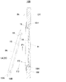
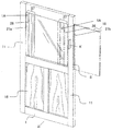
本発明は、スチール製のドア10Bについても何らの障害なく実施することができる。スチール製のドア10B1Aは、右開きであっても左開きであってもよい。また、シール材を介在させて洪水等からの水の浸入防止が図られているものでも良い。ここでは、ドア10Bがガラス窓1A付きのものであり、そのガラス窓1Aを非常用開閉部材20として利用する形態を説明する(図4)。スチール製のドア10Bにおいては、予めガラス板18と窓枠19とを組み合わせた窓枠ユニット1Nとし、窓枠ユニット1Nをドア本体1Mの窓用の開口部Hに対して取付け、取外し自在とすることが好ましい。
(Embodiment 3)
The present invention can be implemented without any obstacles for the
非常用開閉部材20としてのガラス窓1Aを構成する窓枠ユニット1Nは、樹脂成形または板金加工によって額縁状に形成した窓枠19にガラス板18を固定したものであり、窓枠19とガラス板18とは、1ユニットとして一体に取り扱われる。ここで、窓枠19に対するガラス板18の取り付け方に特徴がある。
A window frame unit 1N constituting a
窓枠19は、スチール製のドア10Bの表面に着座するフランジ部19Aと、窓用の開口部Hの内部に入り込んで位置決めされるガイド部19Bとからなる(図4,図5)。フランジ部19Aの下辺部には、開閉操作用の指掛けF,Fが形成されている。また、ガラス板18の左右幅寸法とガイド部19Bの左右幅寸法とは、略一致するように設定されている。他方、ガラス板18に上下寸法は、ガイド部19Bの上下寸法に対して幾分長く設定されている。
The
この結果、窓枠19とガラス板18とを組み合わせたときに、ガラス板18の上下端部がガイド部19Bから突出することとなる。ここで、ガラス板18の下端部がガイド部19Bから下方に突出する突出長さに対して、ガラス板の上端部がガイド部から上方に突出する突出長さのほうが大きくなるように設定されている。一方で、ドア10Bの開口部Hの上端面と下端面には、それぞれガラス板18の突出部を受け入れるための条溝18H,18Hが形成されている。なお、開口部Hの上端面の条溝18Hは、開口部Hの下端面の条溝18Hに対して深く形成されている(図5)。
As a result, when the
上記のような窓枠ユニット1Nは、ドア10Bに対して、その開口部Hの上下面に形成した条溝18H,18Hに窓枠ユニット1Nのガラス板18の上縁部と下縁部とを嵌め込むことによって組み付けられている。このとき、窓枠19のフランジ部19Aは、ドア10Bの開口部Hの周囲を取り囲むように被覆して外観を整えるように機能する。このような窓枠ユニット1Nの組み付け方は、例えば、和風建物における障子戸の建付け構造と同様のものである。したがって、非常用開閉部材20としての採光用のガラス窓1Aは、有事に際して障子戸を取り外すのと同様の操作によってスチール製のドア10Bの一部に簡単に避難用の開口部Hを形成することが出きる。
The window frame unit 1N as described above has the upper and lower edges of the
具体的には、先ず、窓枠19の指掛けF,F(図4)を利用して窓枠ユニット1N全体を上方に持ち上げ、ガラス板18の下縁部を条溝18Hから抜きとる(図5矢印F1)。次いで、窓枠ユニット1Nの下側を手前に引き、ガイド部19Bを開口部Hから外部に脱出させる(図5矢印F2)。次いで、斜め姿勢になった窓枠ユニット1Nを元の姿勢に戻すことなくそのままの姿勢で斜め下に移動させることによってガラス板18の上縁部を条溝18Hから抜き取ることができる(図5矢印F3)。これによって窓枠ユニット1N全体をドア10Bから取り外すことができる。この操作は、簡単ではあるが、構造を理解していないとまごつく場合があるので、事前に一度取外しの練習をしておくことが好ましい。なお、本形態の非常用開閉部材は、屋外側OTからは、取り外すことができないので施錠機構の必要性は希薄である。
Specifically, first, the entire window frame unit 1N is lifted upward using the finger hooks F and F (FIG. 4) of the
(実施の形態4)
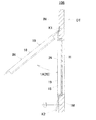
上記非常用開閉部材20としてのガラス窓1Aは、ドア10Bに対する揺動動作によって開閉する構造とすることができる(図6)。例えば、窓枠19のフランジ部19Aの上辺をドア本体1Mにヒンジ金具K1を利用して固定し、フランジ部19Aの下辺を回転クランプ金具K2を用いてドア本体1Mに押し付けるように拘束する構造とすることができる。本形態の非常用開閉部材20は、回転クランプ金具K2を操作してフランジ部19Aの下辺を開放することによって、フランジ部19Aの上辺のヒンジ金具K1を介して窓枠19の下辺を前後に煽るようにして開閉することができる(図6の2点差線)。なお、回転クランプ金具K2は、本発明にいう無鍵施錠手段30である。回転クランプ金具K2による閉塞は、密閉性に優れ、洪水等による水の浸入防止効果も高い。
(Embodiment 4)
The
(実施の形態5)
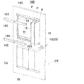
折畳み動作によって開閉する非常用開閉部材20を木製のドア10Bについて実施する場合の構造を例示する(図7)。木製のドア10Bの上半部と下半部とには、いずれも同じサイズの大きな開口部Hが形成されており、各開口部Hは、同じデザインのガラリ板1Gによって塞がれている。ただし、下側のガラリ板1Gは、外観を上側のガラリ板1Gと同一に仕上げたダミーであって開閉するための機構は省かれている。一方、上側のガラリ板1Gは、本発明の非常用開閉部材20として、例えば、アコーディオンドアや折り戸の開閉動作に類似する動作によって開閉する構造である。
(Embodiment 5)
The structure in the case of implementing the emergency opening / closing
ガラリ板1Gは、4枚の丈夫な飾り板16…を布ヒンジ、樹脂ヒンジ、またはヒンジ金具を介してジグザグ折り可能に連結してなる。このガラリ板1Gには、ジグザグ折りにした際に一方の側に揃うこととなる各飾り板16…の上端面および下端面の端部には、上下方向に向けてガイドピンP…が突設されている。各飾り板16の上下寸法は、開口部Hの上下内法寸法相当であり、ガラリ板1Gの展開寸法は、開口部Hの左右内法寸法相当である。
The
非常用開閉部材20としてのガラリ板1Gが組み込まれることとなる木製のドア10Bの開口部Hの上端面と下端面とには、それぞれ水平方向のガイド溝16G,16Gが設けられている。また、上下のガイド溝16G,16Gに沿ってドア10Bの屋外側OTと屋内側1Nとには、ガラリ板1Gの折畳み動作を規制する規制桟16S…が設けられている。それぞれ上下1対の規制桟16S,16Sのうち、ドア10Bの屋外側OTに取り付けられる規制桟16S,16Sは、ドア10Bに取外し不能に固定される。また、屋内側1Nの各規制桟16S,16Sは、両端部に開口部Hの左右の図示しないほぞ穴に挿入する差込みほぞを備え、差込みほぞを抜くことによって取外し可能である。
ガラリ板1Gは、ドア10Bの開口部Hに対して、開口部Hの上下に設けられたガイド溝16G,16GにガイドピンP…を差し入れるとともに、上下各1対の規制桟16S,16Sによってガラリ板1Gの上下2箇所を折畳み動作不能に拘束した状態で組み込まれる。本形態の木製のドア10Bは、屋内側1Nの規制部材16S,16Sを取り外し、ガラリ板1Gをジグザグ折りに折り畳む操作によって閉じられていた開口部Hを避難可能に開放することができる。すなわち、屋内側INの規制桟16S,16Sは、本発明にいう無鍵施錠手段30である。
The
(実施の形態6)
玄関戸等に採用される引き戸11おいてガラス窓1Aを形成するガラス板18に、開閉用部材27が取り付けられている(図8)。開閉用部材27は、溝28が形成されて、非常用開閉部材20を開閉操作を容易にするとともに、ガラス窓3Aを開放したときの開放の行き過ぎを規制する役割を果たす。なお、図8の二点鎖線は、非常用開閉部材20を開放した状態を示し、上記開閉用部材27の一側縁27bが上記縦框11と接触する。他方、非常用開閉部材20を閉塞すると、上記開閉用部材27の他側縁27aが上記縦框11と接触する(実践を参照)。なお、開閉用部材27は、ガラス板18のカバーになるように取り付けることも可能である。
本実施の形態では、左右方向のスライドを容易にするために、ガラス板18の左右の一方のみに配されているが、図3に示すような上下方向のスライドにも適用でき、所定幅の一側面がドアと統一デザインとされている。
(Embodiment 6)
An opening / closing
In this embodiment, in order to facilitate sliding in the left-right direction, the
1A ガラス窓、
10A,11 引き戸、
10B ドア、
16 飾り板
18 ガラス板
19 窓枠、
20 非常用開閉部材、
H 開口部
1A glass window,
10A, 11 sliding doors,
10B door,
16
20 emergency opening and closing member,
H opening
Claims (8)
前記非常用開閉部材は、前記引き戸またはドアに通常使用される固定の構成部材としての態様で組み込まれ、かつ、前記引き戸またはドア全体として統一デザインされていることを特徴とする建物の引き戸またはドア。 An emergency opening / closing member capable of forming an opening of a size that allows a person to pass through when the sliding door or door is closed is incorporated in the sliding door or door of the building,
The emergency opening / closing member is incorporated in a mode as a fixed component usually used for the sliding door or door, and is designed as a unit as the entire sliding door or door. .
The emergency opening / closing member comprises a keyless locking means that can be unlocked without a key only from the interior side of the building in which the sliding door or door is installed. Sliding doors or doors for buildings as described in section
Priority Applications (1)
| Application Number | Priority Date | Filing Date | Title |
|---|---|---|---|
| JP2010030204A JP2011163085A (en) | 2010-02-15 | 2010-02-15 | Sliding door or door of building |
Applications Claiming Priority (1)
| Application Number | Priority Date | Filing Date | Title |
|---|---|---|---|
| JP2010030204A JP2011163085A (en) | 2010-02-15 | 2010-02-15 | Sliding door or door of building |
Publications (1)
| Publication Number | Publication Date |
|---|---|
| JP2011163085A true JP2011163085A (en) | 2011-08-25 |
Family
ID=44594100
Family Applications (1)
| Application Number | Title | Priority Date | Filing Date |
|---|---|---|---|
| JP2010030204A Pending JP2011163085A (en) | 2010-02-15 | 2010-02-15 | Sliding door or door of building |
Country Status (1)
| Country | Link |
|---|---|
| JP (1) | JP2011163085A (en) |
Cited By (4)
| Publication number | Priority date | Publication date | Assignee | Title |
|---|---|---|---|---|
| GB2495298A (en) * | 2011-10-05 | 2013-04-10 | Frank Kelly | Door assembly with escape hatch |
| JP2014015795A (en) * | 2012-07-10 | 2014-01-30 | Toyota Home Kk | Mounting structure of louver |
| JP2016035179A (en) * | 2014-08-04 | 2016-03-17 | Ykk Ap株式会社 | Joinery |
| JP2019170252A (en) * | 2018-03-28 | 2019-10-10 | 株式会社ペティオ | Pet circle and door unit |
Citations (7)
| Publication number | Priority date | Publication date | Assignee | Title |
|---|---|---|---|---|
| JPH0469599U (en) * | 1990-10-30 | 1992-06-19 | ||
| JPH0932419A (en) * | 1995-07-24 | 1997-02-04 | Nippon Cable Syst Inc | Door small window opening / closing device |
| JPH1046931A (en) * | 1996-08-05 | 1998-02-17 | Sanwa Shutter Corp | Emergency escape door |
| JP2000027557A (en) * | 1998-07-10 | 2000-01-25 | Kyoritsu Sash Kogyo Kk | Door with opening window |
| JP2001090450A (en) * | 1999-09-23 | 2001-04-03 | Shuji Saegusa | Door with door |
| JP2001234676A (en) * | 2000-02-24 | 2001-08-31 | Tekken Constr Co Ltd | Basement door with escape door |
| JP2005133496A (en) * | 2003-10-31 | 2005-05-26 | Panahome Corp | Fittings |
-
2010
- 2010-02-15 JP JP2010030204A patent/JP2011163085A/en active Pending
Patent Citations (7)
| Publication number | Priority date | Publication date | Assignee | Title |
|---|---|---|---|---|
| JPH0469599U (en) * | 1990-10-30 | 1992-06-19 | ||
| JPH0932419A (en) * | 1995-07-24 | 1997-02-04 | Nippon Cable Syst Inc | Door small window opening / closing device |
| JPH1046931A (en) * | 1996-08-05 | 1998-02-17 | Sanwa Shutter Corp | Emergency escape door |
| JP2000027557A (en) * | 1998-07-10 | 2000-01-25 | Kyoritsu Sash Kogyo Kk | Door with opening window |
| JP2001090450A (en) * | 1999-09-23 | 2001-04-03 | Shuji Saegusa | Door with door |
| JP2001234676A (en) * | 2000-02-24 | 2001-08-31 | Tekken Constr Co Ltd | Basement door with escape door |
| JP2005133496A (en) * | 2003-10-31 | 2005-05-26 | Panahome Corp | Fittings |
Cited By (5)
| Publication number | Priority date | Publication date | Assignee | Title |
|---|---|---|---|---|
| GB2495298A (en) * | 2011-10-05 | 2013-04-10 | Frank Kelly | Door assembly with escape hatch |
| JP2014015795A (en) * | 2012-07-10 | 2014-01-30 | Toyota Home Kk | Mounting structure of louver |
| JP2016035179A (en) * | 2014-08-04 | 2016-03-17 | Ykk Ap株式会社 | Joinery |
| JP2019170252A (en) * | 2018-03-28 | 2019-10-10 | 株式会社ペティオ | Pet circle and door unit |
| JP7101009B2 (en) | 2018-03-28 | 2022-07-14 | 株式会社ペティオ | Pet circle and door unit |
Similar Documents
| Publication | Publication Date | Title |
|---|---|---|
| EP2764192B1 (en) | Building including a flood defence door assembly with escape hatch | |
| EP3604725B1 (en) | Break-in-resistant intelligent sliding enclosure | |
| KR200471959Y1 (en) | Hand cover frame available for extended window frame system | |
| JP2010209663A (en) | Window device | |
| JP2014114668A (en) | Door of building | |
| JP6767736B2 (en) | Louver structure including movable louver | |
| JP4198015B2 (en) | Evacuation box | |
| JP3172548U (en) | Internal window with ventilation function | |
| JP5444524B2 (en) | Window equipment | |
| JP5100016B2 (en) | Security structure of the opening | |
| JP6051182B2 (en) | Joinery | |
| RU2577706C1 (en) | Anti-breaking window structure | |
| KR200206313Y1 (en) | Opening and shutting window have prevention grille of crimes and prevention net of a harmful insect | |
| RU132121U1 (en) | Burglar-resistant window construction "CALCAN" | |
| JP4291942B2 (en) | Sliding window with security screen | |
| KR102718135B1 (en) | Easy-to-install door device | |
| JP3174281U (en) | Punching type sliding folding door | |
| JP2006124919A (en) | Unitarily-formed crime preventive sash frame | |
| JP4636202B1 (en) | Window joinery | |
| JP2548274Y2 (en) | Sash window | |
| KR200377441Y1 (en) | Pair glass window | |
| JP2005207152A (en) | Building door | |
| JP5118308B2 (en) | Shutter device mounting structure | |
| AU2015303829B2 (en) | A closure assembly | |
| JP3127300U (en) | Telescopic grid |
Legal Events
| Date | Code | Title | Description |
|---|---|---|---|
| A621 | Written request for application examination |
Free format text: JAPANESE INTERMEDIATE CODE: A621 Effective date: 20121023 |
|
| A977 | Report on retrieval |
Free format text: JAPANESE INTERMEDIATE CODE: A971007 Effective date: 20130628 |
|
| A131 | Notification of reasons for refusal |
Effective date: 20131224 Free format text: JAPANESE INTERMEDIATE CODE: A131 |
|
| A02 | Decision of refusal |
Free format text: JAPANESE INTERMEDIATE CODE: A02 Effective date: 20140422 |