JP2017178246A - Work vehicle - Google Patents

Work vehicle Download PDF

Info

Publication number
JP2017178246A
JP2017178246A JP2016072276A JP2016072276A JP2017178246A JP 2017178246 A JP2017178246 A JP 2017178246A JP 2016072276 A JP2016072276 A JP 2016072276A JP 2016072276 A JP2016072276 A JP 2016072276A JP 2017178246 A JP2017178246 A JP 2017178246A
Authority
JP
Japan
Prior art keywords
intake port
engine
vent
disposed
radiator
Prior art date
Legal status (The legal status is an assumption and is not a legal conclusion. Google has not performed a legal analysis and makes no representation as to the accuracy of the status listed.)
Pending
Application number
JP2016072276A
Other languages
Japanese (ja)
Inventor
黒田 智之
Tomoyuki Kuroda
智之 黒田
圭志 絹田
Keishi Kinuta
圭志 絹田
Current Assignee (The listed assignees may be inaccurate. Google has not performed a legal analysis and makes no representation or warranty as to the accuracy of the list.)
Yanmar Co Ltd
Original Assignee
Yanmar Co Ltd
Priority date (The priority date is an assumption and is not a legal conclusion. Google has not performed a legal analysis and makes no representation as to the accuracy of the date listed.)
Filing date
Publication date
Application filed by Yanmar Co Ltd filed Critical Yanmar Co Ltd
Priority to JP2016072276A priority Critical patent/JP2017178246A/en
Publication of JP2017178246A publication Critical patent/JP2017178246A/en
Pending legal-status Critical Current

Links

Images

Abstract

PROBLEM TO BE SOLVED: To prevent water from entering from an intake port into an engine intake path.SOLUTION: A work vehicle 1 includes: an engine 5 mounted on a travel machine body; a cooling fan disposed at one side part of the engine 5; and an engine hood 11 which covers the engine 5 and has vent holes on a side surface facing the cooling fan. An intake port 166 of the engine 5 is disposed facing the vent holes. A shield member 167 covering the intake port 166 in a side view is provided between the intake port 166 and the vent holes.SELECTED DRAWING: Figure 11

Description

本願発明は、例えば農業用のトラクターや乗用型田植機、土木建設用のホイルローダなどの作業車両に関するものである。   The present invention relates to work vehicles such as agricultural tractors, riding rice transplanters, and wheel loaders for civil engineering construction.

従来の作業車両において、走行機体に搭載されたエンジンに冷却用ファンを設け、冷却用ファンの回転で生ずる冷却風によってエンジンを冷却する技術はよく知られている(例えば特許文献1参照)。また、エンジンを覆うボンネットには、冷却用ファンに対向する側面を介してボンネット内に外気を取り込むための通気口が設けられる。   In a conventional work vehicle, a technology is well known in which a cooling fan is provided on an engine mounted on a traveling machine body and the engine is cooled by cooling air generated by the rotation of the cooling fan (see, for example, Patent Document 1). Further, the bonnet that covers the engine is provided with a vent for taking outside air into the bonnet through the side surface facing the cooling fan.

特開2015−223870号公報JP2015-223870A

エンジンの燃焼用空気を取り込む吸気口がボンネット内に配置される構成において、吸気口はボンネット側面に設けられた通気口の近傍に配置されることが多い。しかし、例えば洗車時など、ボンネットに側方から水がかかる状況において、通気口は空気のみならず水も通過させるので、通気口からボンネット内に浸入した水が吸気口を介してエンジンの吸気経路に浸入するという問題があった。   In a configuration in which an intake port for taking in combustion air of an engine is arranged in the bonnet, the intake port is often arranged in the vicinity of a vent provided on the side surface of the bonnet. However, when the bonnet is exposed to water from the side, such as when washing a car, the air vent allows water to pass through as well as the air. There was a problem of getting into.

本願発明は、上記の現状に鑑みてなされたものであり、エンジン吸気経路への吸気口からの水の浸入を防止することを技術的課題としている。   This invention is made | formed in view of said present condition, and makes it the technical subject to prevent permeation of the water from the inlet port to an engine intake path.

本願発明は、走行機体に搭載されたエンジンと、エンジンの一側部に配置された冷却用ファンと、エンジンを覆うとともに冷却用ファンに対向する側面に通気口を有するボンネットを備えた作業車両であって、前記エンジンの吸気口が前記通気口に対峙して配置されるとともに、前記吸気口と前記通気口の間に前記通気口側から見て前記吸気口を覆う遮蔽部材を備えたものである。   The present invention is a work vehicle including an engine mounted on a traveling machine body, a cooling fan disposed on one side of the engine, and a bonnet that covers the engine and has a vent on a side surface facing the cooling fan. The engine intake port is disposed opposite to the vent port, and includes a shielding member that covers the intake port when viewed from the vent port side between the intake port and the vent port. is there.

本願発明において、例えば、前記冷却用ファンを囲うファンシュラウドに前記吸気口が一体成形されるとともに、前記ファンシュラウドに前記遮蔽部材が取り付けられているようにしてもよい。   In the present invention, for example, the air inlet may be integrally formed with a fan shroud surrounding the cooling fan, and the shielding member may be attached to the fan shroud.

また、本願発明において、前記吸気口は下方に向けて開口されている例を挙げることができる。   Moreover, in this invention, the example which the said inlet port is opened toward the downward direction can be mentioned.

また、本願発明は、例えば、前記冷却用ファンと前記通気口の間にラジエータが配置される構成であって、作動油オイルクーラのコア部分が前記通気口と前記ラジエータの間に配置され、前記吸気口が前記ラジエータの上方に配置されており、前記通気口側から見て前記コア部分と前記吸気口が水平方向でずれた位置に配置されているようにしてもよい。   Further, the present invention is, for example, a configuration in which a radiator is disposed between the cooling fan and the vent, and a core portion of a hydraulic oil cooler is disposed between the vent and the radiator, An air intake port may be disposed above the radiator, and the core portion and the air intake port may be disposed at a position shifted in the horizontal direction when viewed from the vent port side.

本願発明の作業車両は、ボンネット側面に設けられた通気口に対峙してエンジンの吸気口が配置されるとともに、吸気口と通気口の間に通気口側から見て吸気口を覆う遮蔽部材を備えているようにしたので、ボンネットに側方から水がかかる状況であっても遮蔽部材によって吸気口への水の浸入が阻止され、エンジン吸気経路への吸気口からの水の浸入を防止することができる。   The work vehicle according to the present invention has an engine intake port facing the vent provided on the side surface of the bonnet, and a shielding member that covers the intake port as viewed from the vent side between the intake port and the vent port. Even if the bonnet is exposed to water from the side, the shielding member prevents water from entering the intake port and prevents water from entering the engine intake path from the intake port. be able to.

本願発明の作業車両において、冷却用ファンを囲うファンシュラウドに吸気口が一体成形されるとともに、ファンシュラウドに遮蔽部材が取り付けられているようにすれば、遮蔽部材を支持するための部材を別途設ける必要がないので、部品点数や製造コストを低減できるとともに、遮蔽部材を簡便に取付けできる。   In the work vehicle of the present invention, if the air inlet is integrally formed with the fan shroud that surrounds the cooling fan, and a shielding member is attached to the fan shroud, a member for supporting the shielding member is separately provided. Since it is not necessary, the number of parts and the manufacturing cost can be reduced, and the shielding member can be easily attached.

また、本願発明の作業車両において、吸気口は下方に向けて開口されているようにすれば、側方からの吸気口への水の浸入をより確実に防止できる。   Further, in the work vehicle of the present invention, if the intake port is opened downward, water can be more reliably prevented from entering the intake port from the side.

また、本願発明の作業車両は、例えば冷却用ファンと通気口の間にラジエータが配置される構成であって、作動油オイルクーラのコア部分が通気口とラジエータの間に配置され、吸気口がラジエータの上方に配置されており、通気口側から見てコア部分と吸気口が水平方向でずれた位置に配置されているようにすれば、作動油オイルクーラに留まって発生する熱が吸気口に直接吸引されないようにすることができる。これにより、吸気口から取り込まれる燃焼用空気に関し、作動油オイルクーラの発熱に起因する温度上昇を抑制でき、ひいてはエンジン出力の低下を抑制できる。   Further, the work vehicle of the present invention has a configuration in which, for example, a radiator is disposed between the cooling fan and the vent, the core portion of the hydraulic oil cooler is disposed between the vent and the radiator, and the intake port is If it is arranged above the radiator and the core part and the intake port are arranged in a horizontal position when viewed from the vent side, the heat generated by staying in the hydraulic oil cooler It is possible to prevent direct suction. Thereby, regarding the combustion air taken in from the intake port, it is possible to suppress the temperature rise caused by the heat generation of the hydraulic oil cooler, and thus the engine output can be prevented from decreasing.

実施形態における乗用型田植機の左側面図である。It is a left view of the riding type rice transplanter in the embodiment. 乗用型田植機の平面図である。It is a top view of a riding type rice transplanter. 走行機体の左側面図である。It is a left view of a traveling body. 走行機体の平面図である。It is a top view of a traveling body. 操縦ハンドルを省略した運転操作部の平面図である。It is a top view of the driving operation part which abbreviate | omitted the steering handle. 乗用型田植機の駆動系統図である。It is a drive system figure of a riding type rice transplanter. 乗用型田植機の油圧回路図である。It is a hydraulic circuit diagram of a riding type rice transplanter. 走行機体前部の正面断面図である。It is front sectional drawing of a traveling machine body front part. エンジン及びミッションケースの拡大右側面図である。It is an expansion right view of an engine and a transmission case. ボンネットの拡大右側面図である。It is an expansion right side view of a bonnet. ボンネット内部の拡大右側面図である。It is an expansion right side view inside a bonnet. ラジエータ及びファンシュラウド周辺を示す斜視図である。It is a perspective view which shows a radiator and a fan shroud periphery. ファンシュラウド及びエアクリーナとともに作動油径路を示す平面図である。It is a top view which shows a hydraulic-oil path with a fan shroud and an air cleaner. ファンシュラウド及び吸気管を一部断面で示す平面図である。It is a top view which shows a fan shroud and an intake pipe in a partial cross section. 吸気口周辺の拡大右側面である。It is an enlarged right side surface around the inlet.

以下に、本願発明を具体化した実施形態を、作業車両である8条植え式の乗用型田植機1(以下、単に田植機1という)に適用した場合の図面に基づいて説明する。なお、以下の説明では、走行機体2の進行方向に向かって左側を単に左側と称し、同じく進行方向に向かって右側を単に右側と称する。   Hereinafter, an embodiment embodying the present invention will be described with reference to the drawings when applied to an eight-row planting type rice transplanter 1 (hereinafter, simply referred to as a rice transplanter 1) as a work vehicle. In the following description, the left side in the traveling direction of the traveling machine body 2 is simply referred to as the left side, and the right side in the traveling direction is also simply referred to as the right side.

まず、図1〜図4を参照しながら、田植機1の概要について説明する。実施形態の田植機1は、走行部としての左右一対の前車輪3及び同じく左右一対の後車輪4によって支持された走行機体2を備えている。走行機体2の前部にはエンジン5が搭載されている。エンジン5からの動力を後方のミッションケース6に伝達して、前車輪3及び後車輪4を駆動させることにより、走行機体2が前後進走行するように構成されている。ミッションケース6の左右側方にフロントアクスルケース7を突出させ、フロントアクスルケース7から左右外向きに延びる前車軸36に前車輪3が舵取り可能に取り付けられている。ミッションケース6の後方に筒状フレーム8を突出させ、筒状フレーム8の後端側にリヤアクスルケース9を固設し、リヤアクスルケース9から左右外向きに延びる後車軸37に後車輪4が取り付けられている。   First, the outline | summary of the rice transplanter 1 is demonstrated, referring FIGS. 1-4. The rice transplanter 1 according to the embodiment includes a traveling machine body 2 supported by a pair of left and right front wheels 3 and a pair of left and right rear wheels 4 as a traveling unit. An engine 5 is mounted on the front portion of the traveling machine body 2. Power from the engine 5 is transmitted to the rear transmission case 6 to drive the front wheels 3 and the rear wheels 4 so that the traveling machine body 2 travels forward and backward. A front axle case 7 projects from the left and right sides of the transmission case 6, and the front wheels 3 are attached to a front axle 36 extending from the front axle case 7 to the left and right so as to be steerable. A cylindrical frame 8 protrudes behind the transmission case 6, a rear axle case 9 is fixed to the rear end side of the cylindrical frame 8, and the rear wheel 4 is attached to a rear axle 37 that extends outward from the rear axle case 9 to the left and right. ing.

図1及び図2に示されるように、走行機体2の前部及び中央部の上面側には、オペレータ搭乗用の作業ステップ(車体カバー)10が設けられている。作業ステップ10の前部の上方にはボンネット11が配置され、ボンネット11の内部にエンジン5を設置している。作業ステップ10の上面のうちボンネット11の後部側方に、足踏み操作用の走行変速ペダル12が配置されている。詳細は省略するが、実施形態の田植機1は、走行変速ペダル12の踏み込み量に応じた変速電動モータの駆動にて、ミッションケース6の油圧無段変速機40から出力される変速動力を調節するように構成されている。   As shown in FIGS. 1 and 2, an operator boarding work step (vehicle body cover) 10 is provided on the upper surface side of the front part and the center part of the traveling machine body 2. A bonnet 11 is disposed above the front part of the work step 10, and the engine 5 is installed inside the bonnet 11. A travel speed change pedal 12 for stepping operation is disposed on the upper side of the work step 10 on the rear side of the bonnet 11. Although details are omitted, the rice transplanter 1 according to the embodiment adjusts the shift power output from the hydraulic continuously variable transmission 40 of the transmission case 6 by driving the variable speed electric motor according to the depression amount of the travel shift pedal 12. Is configured to do.

また、ボンネット11の後部上面側にある運転操作部13には、操縦ハンドル14と走行主変速レバー15と昇降操作具としての作業レバー16とが設けられている(図5参照)。作業ステップ10の上面のうちボンネット11の後方には、シートフレーム17を介して操縦座席18が配置されている。なお、ボンネット11の左右側方には、作業ステップ10を挟んで左右の予備苗載台24が設けられている。   In addition, a steering handle 14, a traveling main transmission lever 15, and a work lever 16 as a lifting operation tool are provided in the driving operation unit 13 on the rear upper surface side of the bonnet 11 (see FIG. 5). A steering seat 18 is disposed behind the bonnet 11 on the upper surface of the work step 10 via a seat frame 17. Note that left and right spare seedling platforms 24 are provided on the left and right sides of the bonnet 11 with the operation step 10 interposed therebetween.

走行機体2の後端部にリンクフレーム19を立設する。リンクフレーム19には、ロワーリンク20及びトップリンク21からなる昇降リンク機構22を介して、8条植え用の苗植付装置23が昇降可能に連結されている。この場合、苗植付装置23の前面側に、ローリング支点軸(図示省略)を介してヒッチブラケット38を設けている。昇降リンク機構22の後部側にヒッチブラケット38を連結することによって、走行機体2の後方に苗植付装置23を昇降動可能に配置している。筒状フレーム8の上面後部に、油圧式の昇降シリンダ39のシリンダ基端側を上下回動可能に支持させる。昇降シリンダ39のロッド先端側はロワーリンク20に連結している。昇降シリンダ39の伸縮動にて昇降リンク機構22を上下回動させる結果、苗植付装置23が昇降動する。なお、苗植付装置23は前記ローリング支点軸回りに回動して左右方向の傾斜姿勢を変更可能に構成している。   A link frame 19 is erected at the rear end of the traveling machine body 2. An eight-row seedling planting device 23 is connected to the link frame 19 via an elevating link mechanism 22 including a lower link 20 and a top link 21 so as to be elevable. In this case, a hitch bracket 38 is provided on the front side of the seedling planting device 23 via a rolling fulcrum shaft (not shown). By connecting a hitch bracket 38 to the rear side of the lifting link mechanism 22, the seedling planting device 23 is disposed behind the traveling machine body 2 so as to be movable up and down. The cylinder base end side of the hydraulic lift cylinder 39 is supported on the rear upper surface of the cylindrical frame 8 so as to be vertically rotatable. The rod tip side of the lifting cylinder 39 is connected to the lower link 20. As a result of vertically moving the lifting link mechanism 22 by the expansion and contraction of the lifting cylinder 39, the seedling planting device 23 moves up and down. Note that the seedling planting device 23 is configured to be rotatable about the rolling fulcrum axis so as to be able to change the inclined posture in the left-right direction.

オペレータは、作業ステップ10の側方にある乗降ステップ25から作業ステップ10上に搭乗し、運転操作にて圃場内を移動しながら、苗植付装置23を駆動させて圃場に苗を植え付ける苗植え作業(田植え作業)を実行する。なお、苗植え作業中において、苗植付装置23には、予備苗載台24上の苗マットをオペレータが随時補給する。   The operator gets on the work step 10 from the boarding / alighting step 25 on the side of the work step 10 and drives the seedling planting device 23 to move the seedling planting device 23 and move the seedling planting in the field while moving in the field by the driving operation. Perform work (rice planting work). During the seedling planting operation, the operator replenishes the seedling planting device 23 with a seedling mat on the preliminary seedling mounting table 24 as needed.

図1及び図2に示すように、苗植付装置23は、エンジン5からミッションケース6を経由した動力が伝達される植付入力ケース26と、植付入力ケース26に連結する八条用四組(二条で一組)の植付伝動ケース27と、各植付伝動ケース27の後端側に設けられた苗植機構28と、八条植え用の苗載台29と、各植付伝動ケース27の下面側に配置された田面均平用のフロート32とを備えている。苗植機構28には、一条分二本の植付爪30を有するロータリケース31が設けられている。植付伝動ケース27に二条分のロータリケース31が配置されている。ロータリケース31の一回転によって、二本の植付爪30が各々一株ずつの苗を切り取ってつかみ、フロート32にて整地された田面に植え付ける。苗植付装置23の前面側には、圃場面を均す(整地する)整地装置としての整地ロータ85を昇降動可能に設けている。   As shown in FIGS. 1 and 2, the seedling planting device 23 includes a planting input case 26 to which power is transmitted from the engine 5 via the mission case 6, and four sets of eight strips connected to the planting input case 26. Planting transmission case 27 (one set in Nijo), seedling planting mechanism 28 provided on the rear end side of each planting transmission case 27, seedling mount 29 for eight-row planting, and each planting transmission case 27 And a float 32 for uniforming the surface of the surface. The seedling planting mechanism 28 is provided with a rotary case 31 having two planting claws 30 for one line. Two rotary cases 31 are arranged in the planting transmission case 27. By one rotation of the rotary case 31, the two planting claws 30 cut out and grasp one seedling each, and plant it on the field leveled by the float 32. On the front side of the seedling planting device 23, a leveling rotor 85 as a leveling device for leveling (leveling) the farm scene is provided so as to be movable up and down.

詳細は後述するが、エンジン5からミッションケース6を経由した動力は、前車輪3及び後車輪4に伝達されるだけでなく、苗植付装置23の植付入力ケース26にも伝達される。この場合、ミッションケース6から苗植付装置23に向かう動力は、リヤアクスルケース9の右側上部に設けられた株間変速ケース75に一旦伝達され、株間変速ケース75から植付入力ケース26に動力伝達される。当該伝達された動力にて、各苗植機構28や苗載台29が駆動する。株間変速ケース75には、植え付けられる苗の株間を例えば疎植、標準植又は密植等に切り換える株間変速機構76と、苗植付装置23への動力伝達を継断する植付クラッチ77とが内蔵されている(図6参照)。   Although details will be described later, the power from the engine 5 via the transmission case 6 is transmitted not only to the front wheels 3 and the rear wheels 4, but also to the planting input case 26 of the seedling planting device 23. In this case, the power from the transmission case 6 toward the seedling planting device 23 is once transmitted to the inter-plant transmission case 75 provided on the upper right side of the rear axle case 9, and is transmitted from the inter-plant transmission case 75 to the planting input case 26. The The seedling planting mechanism 28 and the seedling mount 29 are driven by the transmitted power. The inter-strain shifting case 75 includes an inter-strain shifting mechanism 76 that switches between planted seedlings to, for example, sparse planting, standard planting, or dense planting, and a planting clutch 77 that interrupts power transmission to the planting planting device 23. (See FIG. 6).

なお、苗植付装置23の左右外側にはサイドマーカ33を備えている。サイドマーカ33は、筋引き用のマーカ輪体34と、マーカ輪体34を回転可能に軸支するマーカアーム35とを有している。各マーカアーム35の基端側が苗植付装置23の左右外側に左右回動可能に軸支されている。サイドマーカ33は、運転操作部13にある作業レバー16の操作に基づき、次工程での基準となる軌跡を田面に着地して形成する作業姿勢と、マーカ輪体34を上昇させて田面から離間させた非作業姿勢とに回動可能に構成されている。   A side marker 33 is provided on the left and right outside of the seedling planting device 23. The side marker 33 includes a marker ring body 34 for muscle pulling and a marker arm 35 that pivotally supports the marker ring body 34 so as to be rotatable. The base end side of each marker arm 35 is pivotally supported on the left and right outer sides of the seedling planting device 23 so as to be rotatable left and right. The side marker 33 is moved away from the surface by raising the marker wheel body 34 based on the operation posture of the operation lever 16 in the driving operation unit 13 and forming a trajectory as a reference in the next process by landing on the surface. The non-working posture is configured to be rotatable.

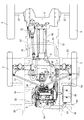
図3及び図4に示すように、走行機体2は前後に延びる左右一対の機体フレーム50を備えている。各機体フレーム50は前部フレーム51と後部フレーム52とに二分割されている。前部フレーム51の後端部と後部フレーム52の前端部とが左右横長の中間連結フレーム53に溶接固定されている。左右一対の前部フレーム51の前端部は前フレーム54に溶接固定されている。左右一対の後部フレーム52の後端側は後フレーム55に溶接固定されている。前フレーム54、左右両前部フレーム51及び中間連結フレーム53は平面視四角枠状に構成されている。同様に、中間連結フレーム53、左右両後部フレーム52及び後フレーム55も平面視四角枠状に構成されている。   As shown in FIGS. 3 and 4, the traveling machine body 2 includes a pair of left and right machine body frames 50 extending in the front-rear direction. Each body frame 50 is divided into a front frame 51 and a rear frame 52. The rear end portion of the front frame 51 and the front end portion of the rear frame 52 are welded and fixed to a laterally long intermediate connection frame 53. The front ends of the pair of left and right front frames 51 are fixed to the front frame 54 by welding. The rear end sides of the left and right rear frames 52 are fixed to the rear frame 55 by welding. The front frame 54, the left and right front frames 51, and the intermediate connection frame 53 are configured in a square frame shape in plan view. Similarly, the intermediate connection frame 53, the left and right rear frames 52, and the rear frame 55 are also configured in a square frame shape in plan view.

図4に示すように、左右両前部フレーム51の前寄り部位は、前後二本のベースフレーム56によって連結されている。当該各ベースフレーム56の中間部は、左右両前部フレーム51よりも低く位置するようにU字形に折り曲げられた形状に形成されている。各ベースフレーム56の左右端部は、対応する前部フレーム51に溶接固定されている。複数の防振ゴム58を介して、前後両ベースフレーム56にエンジン5が搭載され防振支持されている。前側のベースフレーム56は、これに溶接固定された前中継フレーム59を介して前フレーム54に連結されている。後側のベースフレーム56は、後中継ブラケット60(図9参照)を介してミッションケース6の前部に連結されている。   As shown in FIG. 4, the front portions of the left and right front frames 51 are connected by two front and rear base frames 56. An intermediate portion of each base frame 56 is formed in a shape bent into a U shape so as to be positioned lower than the left and right front frames 51. The left and right end portions of each base frame 56 are fixed to the corresponding front frame 51 by welding. The engine 5 is mounted on and supported by the front and rear base frames 56 via a plurality of vibration isolating rubbers 58. The front base frame 56 is connected to the front frame 54 via a front relay frame 59 fixedly welded thereto. The rear base frame 56 is connected to the front portion of the transmission case 6 via a rear relay bracket 60 (see FIG. 9).

図4から分かるように、左右両前部フレーム51の後寄り部位は、ミッションケース6の左右両側に突出したフロントアクスルケース7に連結されている。中間連結フレーム53の中央側には、側面視で後斜め下向きに延びるU字状フレーム61の左右両端部が溶接固定されている。U字状フレーム61の中間部がミッションケース6とリヤアクスルケース9とをつなぐ筒状フレーム8の中途部に連結されている(図3及び図4参照)。後フレーム55の中間部には、左右二本のリンクフレーム19の上端側が溶接固定されている。左右両リンクフレーム19の下端側には左右横長のリヤアクスル支持フレーム63の中間部が溶接固定されている。リヤアクスル支持フレーム63の左右両端部がリヤアクスルケース9に連結されている。なお、左側の前部フレーム51に外向き突設されたステップ支持台64の下方に、エンジン5の排気音を低減させるマフラー65が配置されている。   As can be seen from FIG. 4, the rear portions of the left and right front frames 51 are connected to a front axle case 7 projecting from the left and right sides of the mission case 6. The left and right ends of a U-shaped frame 61 extending rearward and obliquely downward in a side view are welded and fixed to the center side of the intermediate connection frame 53. The middle part of the U-shaped frame 61 is connected to the middle part of the cylindrical frame 8 that connects the transmission case 6 and the rear axle case 9 (see FIGS. 3 and 4). The upper ends of the two left and right link frames 19 are welded and fixed to the middle portion of the rear frame 55. An intermediate portion of a horizontally elongated rear axle support frame 63 is fixed to the lower ends of the left and right link frames 19 by welding. The left and right ends of the rear axle support frame 63 are connected to the rear axle case 9. A muffler 65 for reducing the exhaust noise of the engine 5 is disposed below the step support base 64 projecting outward from the left front frame 51.

図3及び図4に示すように、エンジン5の後方に配置されたミッションケース6の前部には、パワーステアリングユニット66が設けられている。詳細は省略するが、パワーステアリングユニット66の上面に立設されるハンドルポスト67の内部にハンドル軸が回動可能に配置される。ハンドル軸の上端側に操縦ハンドル14が固定されている。パワーステアリングユニット66の下面側には操舵出力軸(図示省略)が下向きに突出している。当該操舵出力軸には、左右の前車輪3を操舵する操舵杆68(図4参照)がそれぞれ連結されている。   As shown in FIGS. 3 and 4, a power steering unit 66 is provided at the front portion of the transmission case 6 disposed behind the engine 5. Although details are omitted, a handle shaft is rotatably disposed inside a handle post 67 standing on the upper surface of the power steering unit 66. A steering handle 14 is fixed to the upper end side of the handle shaft. On the lower surface side of the power steering unit 66, a steering output shaft (not shown) protrudes downward. A steering rod 68 (see FIG. 4) for steering the left and right front wheels 3 is connected to the steering output shaft.

実施形態のエンジン5は、出力軸70(クランク軸)を左右方向に向けて前後両ベースフレーム56の中間部上に配置されている。エンジン5の左右幅は左右両前部フレーム51間の内法寸法よりも小さく、エンジン5の下部側は、前後両ベースフレーム56の中間部上に配置された状態で、左右両前部フレーム51よりも下側に露出している。この場合、エンジン5の出力軸70(軸線)は、側面視で左右両前部フレーム51と重なる位置にある。エンジン5の左右一側面(実施形態では左側面)には、エンジン5の排気系に連通する排気管69が配置されている。排気管69の基端側がエンジン5の各気筒に接続され、排気管69の先端側がマフラー65の排気入口側に接続されている。   The engine 5 of the embodiment is disposed on an intermediate portion of the front and rear base frames 56 with the output shaft 70 (crank shaft) directed in the left-right direction. The left and right widths of the engine 5 are smaller than the internal dimensions between the left and right front frames 51, and the lower side of the engine 5 is disposed on the middle part of the front and rear base frames 56, and the left and right front frames 51 It is exposed to the lower side. In this case, the output shaft 70 (axis line) of the engine 5 is in a position overlapping the left and right front frames 51 in a side view. An exhaust pipe 69 communicating with the exhaust system of the engine 5 is disposed on one of the left and right side surfaces (left side surface in the embodiment) of the engine 5. The proximal end side of the exhaust pipe 69 is connected to each cylinder of the engine 5, and the distal end side of the exhaust pipe 69 is connected to the exhaust inlet side of the muffler 65.

図5に示す運転操作部13において、走行主変速レバー15は、操縦ハンドル14を挟んだ左右一方側(実施形態では左側)に位置している。運転操作部13に形成したガイド溝83に沿って走行主変速レバー15を操作することによって、田植機1の走行モードを前進、中立、後進、苗継及び移動の各モードに切り換えるように構成している。作業レバー16は、操縦ハンドル14を挟んだ左右他方側(実施形態では右側)に位置している。作業レバー16は、苗植付装置23の昇降操作、植付クラッチ77の継断操作及び左右サイドマーカ33の選択操作という複数の操作を単独で担うものであり、十字方向に操作可能に構成している。   In the driving operation unit 13 shown in FIG. 5, the traveling main transmission lever 15 is located on one of the left and right sides (left side in the embodiment) with the steering handle 14 in between. By operating the traveling main speed change lever 15 along the guide groove 83 formed in the driving operation unit 13, the traveling mode of the rice transplanter 1 is switched to forward, neutral, backward, seedling and movement modes. ing. The work lever 16 is located on the left and right other side (right side in the embodiment) across the steering handle 14. The work lever 16 independently performs a plurality of operations such as raising / lowering the seedling planting device 23, switching operation of the planting clutch 77, and selection operation of the left and right side markers 33, and is configured to be operable in the cross direction. ing.

この場合、作業レバー16を一回前傾操作すると苗植付装置23が下降し、もう一回前傾操作すると植付クラッチ77が入り作動する(動力接続状態になる)。逆に、作業レバー16を一回後傾操作すると植付クラッチ77が切り作動し(動力遮断状態になり)、もう一回後傾操作すると苗植付装置23が上昇する。苗植付装置23の昇降動作を取り止める場合は、作業レバー16を逆方向に傾動操作する。例えば苗植付装置23の下降動を途中で停止させる場合は作業レバー16を後傾操作すればよい。作業レバー16を一回左へ傾動操作すると左側のサイドマーカ33が作業姿勢となり、もう一回左へ傾動操作すると左側のサイドマーカ33が非作業姿勢に戻る。作業レバー16を一回右へ傾動操作すると右側のサイドマーカ33が作業姿勢となり、もう一回右へ傾動操作すると右側のサイドマーカ33が非作業姿勢に戻る。   In this case, if the operation lever 16 is tilted forward once, the seedling planting device 23 is lowered, and if it is tilted forward once again, the planting clutch 77 is engaged and activated (becomes a power connection state). Conversely, when the operation lever 16 is tilted once backward, the planting clutch 77 is turned off (becomes in a power cut-off state), and when it is tilted again once, the seedling planting device 23 is raised. When stopping the raising / lowering operation of the seedling planting device 23, the operation lever 16 is tilted in the reverse direction. For example, when the lowering movement of the seedling planting device 23 is stopped halfway, the work lever 16 may be tilted backward. When the work lever 16 is tilted once to the left, the left side marker 33 is in the working position, and when it is tilted left again, the left side marker 33 is returned to the non-working position. When the work lever 16 is tilted to the right once, the right side marker 33 is in the working position, and when the work lever 16 is tilted to the right again, the right side marker 33 is returned to the non-working position.

次に、図6を参照しながら、田植機1の駆動系統について説明する。エンジン5の出力軸70はエンジン5の左右両側面から外向きに突出している。出力軸70のうちエンジン5左側面から突出した突端部にエンジン出力プーリ72を設け、ミッションケース6から左外側に突出したミッション入力軸71にミッション入力プーリ73を設け、両プーリ72,73に伝達ベルト82を巻き掛けている。両プーリ72,73及び伝達ベルト82を介して、エンジン5からミッションケース6に動力伝達する。   Next, the drive system of the rice transplanter 1 will be described with reference to FIG. The output shaft 70 of the engine 5 protrudes outward from the left and right side surfaces of the engine 5. An engine output pulley 72 is provided at the protruding end of the output shaft 70 that protrudes from the left side of the engine 5, a mission input pulley 73 is provided at the mission input shaft 71 that protrudes outward from the mission case 6, and is transmitted to both pulleys 72, 73. A belt 82 is wound around. Power is transmitted from the engine 5 to the transmission case 6 via both pulleys 72 and 73 and the transmission belt 82.

ミッションケース6内には、油圧ポンプ40a及び油圧モータ40bからなる油圧無段変速機40、遊星歯車装置41、油圧無段変速機40及び遊星歯車装置41を経由した変速動力を複数段に変速する歯車式副変速機構42、遊星歯車装置41から歯車式副変速機構42への動力伝達を継断する主クラッチ43、並びに、歯車式副変速機構42からの出力を制動させる走行ブレーキ44等を備えている。ミッション入力軸71からの動力で油圧ポンプ40aを駆動させ、油圧ポンプ40aから油圧モータ40bに作動油を供給し、油圧モータ40bから変速動力が出力される。油圧モータ40bの変速動力は、遊星歯車装置41及び主クラッチ43を介して歯車式副変速機構42に伝達される。そして、歯車式副変速機構42から、前後車輪3,4と苗植付装置23との二方向に分岐して動力伝達される。   In the transmission case 6, the transmission power through the hydraulic continuously variable transmission 40, the planetary gear device 41, the hydraulic continuously variable transmission 40, and the planetary gear device 41 including the hydraulic pump 40 a and the hydraulic motor 40 b is shifted to a plurality of stages. A gear-type sub-transmission mechanism 42, a main clutch 43 that interrupts power transmission from the planetary gear unit 41 to the gear-type sub-transmission mechanism 42, a traveling brake 44 that brakes the output from the gear-type sub-transmission mechanism 42, and the like. ing. The hydraulic pump 40a is driven by power from the mission input shaft 71, hydraulic oil is supplied from the hydraulic pump 40a to the hydraulic motor 40b, and variable speed power is output from the hydraulic motor 40b. The speed change power of the hydraulic motor 40 b is transmitted to the gear type subtransmission mechanism 42 via the planetary gear device 41 and the main clutch 43. Then, power is transmitted from the gear-type sub-transmission mechanism 42 by branching in the two directions of the front and rear wheels 3 and 4 and the seedling planting device 23.

前後車輪3,4に向かう分岐動力の一部は、歯車式副変速機構42から差動歯車機構45を介して、フロントアクスルケース7の前車軸36に伝達され、左右前車輪3を回転駆動させる。前後車輪3,4に向かう分岐動力の残りは、歯車式副変速機構42から、自在継手軸46、リヤアクスルケース9内のリヤ駆動軸47、左右一対の摩擦クラッチ48及び歯車式減速機構49を介して、リヤアクスルケース9の後車軸37に伝達され、左右後車輪4を回転駆動させる。走行ブレーキ44を作動させた場合は、歯車式副変速機構42からの出力がなくなるので、前後車輪3,4共にブレーキがかかる。また、田植機1を旋回させる場合は、リヤアクスルケース9内の旋回内側の摩擦クラッチ48を切り作動させて旋回内側の後車輪4を自由回転させ、動力伝達される旋回外側の後車輪4の回転駆動によって旋回する。   Part of the branching power toward the front and rear wheels 3 and 4 is transmitted from the gear-type auxiliary transmission mechanism 42 via the differential gear mechanism 45 to the front axle 36 of the front axle case 7 to drive the left and right front wheels 3 to rotate. . The remainder of the branching power toward the front and rear wheels 3, 4 is transferred from the gear-type sub-transmission mechanism 42 through the universal joint shaft 46, the rear drive shaft 47 in the rear axle case 9, a pair of left and right friction clutches 48, and a gear-type reduction mechanism 49. Thus, the rear axle case 9 is transmitted to the rear axle 37 to drive the left and right rear wheels 4 to rotate. When the traveling brake 44 is operated, the output from the gear-type subtransmission mechanism 42 is lost, so that the front and rear wheels 3 and 4 are braked. When the rice transplanter 1 is turned, the friction clutch 48 inside the turning inside the rear axle case 9 is turned off to rotate the rear wheel 4 inside the turning freely, and the rotation of the rear wheel 4 outside the turning to which power is transmitted is rotated. It turns by driving.

リヤアクスルケース9内には、整地ロータ85への動力継断用の整地クラッチ84を有するロータ駆動ユニット86を備えている。歯車式副変速機構42から自在継手軸46に伝達された動力はロータ駆動ユニット86にも分岐して伝達され、ロータ駆動ユニット86から自在継手軸87を介して整地ロータ85に動力伝達される。整地ロータ85の回転駆動によって圃場面が均される。   A rotor drive unit 86 having a leveling clutch 84 for power transmission to the leveling rotor 85 is provided in the rear axle case 9. The power transmitted from the gear-type subtransmission mechanism 42 to the universal joint shaft 46 is also branched and transmitted to the rotor drive unit 86, and is transmitted from the rotor drive unit 86 to the leveling rotor 85 via the universal joint shaft 87. The farm scene is leveled by the rotational drive of the leveling rotor 85.

苗植付装置23に向かう分岐動力は、自在継手軸付きのPTO伝動軸機構74を介して株間変速ケース75に伝達される。株間変速ケース75内には、植え付けられる苗の株間を例えば疎植、標準植又は密植等に切り換える株間変速機構76と、苗植付装置23への動力伝達を継断する植付クラッチ77とを備えている。株間変速ケース75に伝達された動力は、株間変速機構76、植付クラッチ77及び自在継手軸78を介して植付入力ケース26に伝達される。   The branching power toward the seedling planting device 23 is transmitted to the inter-strain transmission case 75 via the PTO transmission shaft mechanism 74 with a universal joint shaft. In the inter-strain shifting case 75, an inter-strain shifting mechanism 76 that switches between seedlings to be planted, for example, to sparse planting, standard planting, or dense planting, and a planting clutch 77 that interrupts power transmission to the planting planting device 23 are provided. I have. The power transmitted to the inter-plant transmission case 75 is transmitted to the planting input case 26 via the inter-plant transmission mechanism 76, the planting clutch 77, and the universal joint shaft 78.

植付入力ケース26内には、苗載台29を横送り移動させる横送り機構79と、苗載台29上の苗マットを縦送り搬送させる苗縦送り機構80と、植付入力ケース26から各植付伝動ケース27に動力伝達する植付出力軸81とを備えている。植付入力ケース26に伝達された動力によって、横送り機構79及び苗縦送り機構80が駆動し、苗載台29を連続的に往復で横送り移動させ、苗載台29が往復移動端(往復移動の折返し点)に到達したときに苗載台29上の苗マットを間欠的に縦送り搬送する。植付入力ケース26から植付出力軸81を経由した動力は各植付伝動ケース27に伝達され、各植付伝動ケース27のロータリケース31並びに植付爪30を回転駆動させる。なお、施肥装置を設ける場合は株間変速ケース75から施肥装置に動力伝達される。   In the planting input case 26, a lateral feed mechanism 79 that moves the seedling platform 29 laterally, a seedling vertical feed mechanism 80 that transports the seedling mat on the seedling platform 29 longitudinally, and the planting input case 26. A planting output shaft 81 that transmits power to each planting transmission case 27 is provided. By the power transmitted to the planting input case 26, the lateral feed mechanism 79 and the seedling vertical feed mechanism 80 are driven, and the seedling stage 29 is continuously reciprocally moved in the lateral direction. The seedling mat on the seedling table 29 is intermittently transported vertically when reaching the turning point of the reciprocating movement. Power from the planting input case 26 via the planting output shaft 81 is transmitted to each planting transmission case 27, and the rotary case 31 and the planting claw 30 of each planting transmission case 27 are driven to rotate. In addition, when providing a fertilizer, motive power is transmitted from the inter-strain transmission case 75 to a fertilizer.

次に、図7を参照しながら、田植機1の油圧回路構造について説明する。田植機1の油圧回路90には、油圧無段変速機40の構成要素である油圧ポンプ40a及び油圧モータ40bと、チャージポンプ91及び作業ポンプ92とを備える。油圧ポンプ40a、チャージポンプ91及び作業ポンプ92がエンジン5の動力によって駆動する。油圧ポンプ40aと油圧モータ40bとは、閉ループ油路93を介してそれぞれの吸入側及び吐出側に接続している。チャージポンプ91を閉ループ油路93に接続している。走行変速ペダル12の踏み込み量に応じた変速電動モータの駆動によって、油圧ポンプ40aの斜板角度を調節し、油圧モータ40bを正転又は逆転駆動させるように構成している。油圧無段変速機40のチャージドレン継手121(図13参照)から排出される作動油は作動油オイルクーラ122を介して作動油戻し継手123(図13参照)からミッションケース6内部に戻される。   Next, the hydraulic circuit structure of the rice transplanter 1 will be described with reference to FIG. The hydraulic circuit 90 of the rice transplanter 1 includes a hydraulic pump 40 a and a hydraulic motor 40 b that are components of the hydraulic continuously variable transmission 40, a charge pump 91, and a work pump 92. The hydraulic pump 40a, the charge pump 91, and the work pump 92 are driven by the power of the engine 5. The hydraulic pump 40 a and the hydraulic motor 40 b are connected to the respective suction side and discharge side via a closed loop oil passage 93. A charge pump 91 is connected to the closed loop oil passage 93. The swash plate angle of the hydraulic pump 40a is adjusted by driving the speed change electric motor according to the depression amount of the travel speed change pedal 12, and the hydraulic motor 40b is driven forward or reverse. The hydraulic oil discharged from the charge drain joint 121 (see FIG. 13) of the hydraulic continuously variable transmission 40 is returned to the inside of the transmission case 6 from the hydraulic oil return joint 123 (see FIG. 13) via the hydraulic oil cooler 122.

作業ポンプ92は、操縦ハンドル14の操作を補助するパワーステアリングユニット66に接続している。パワーステアリングユニット66は、操向油圧切換弁94及び操向油圧モータ95を備えている。操縦ハンドル14の操作によって操向油圧切換弁94を切換作動させて操向油圧モータ95を駆動させ、操縦ハンドル14の操作を補助する。その結果、左右前車輪3を小さい操作力で簡単に操舵できる。   The work pump 92 is connected to a power steering unit 66 that assists the operation of the steering handle 14. The power steering unit 66 includes a steering hydraulic pressure switching valve 94 and a steering hydraulic motor 95. By operating the steering handle 14, the steering hydraulic pressure switching valve 94 is switched to drive the steering hydraulic motor 95 to assist the operation of the steering handle 14. As a result, the left and right front wheels 3 can be easily steered with a small operating force.

パワーステアリングユニット66はフローデバイダ96に接続している。フローデバイダ96は第一油路97と第二油路98とに分岐している。第一油路97は、昇降シリンダ39に作動油を供給する昇降切換弁99に接続している。昇降切換弁99は、昇降シリンダ39に作動油を供給する供給位置99aと、昇降シリンダ39から作動油を排出する排出位置99bとの二位置に切換可能な四ポート二位置切換形の機械式切換弁である。作業レバー16の操作で昇降切換弁99を切換作動させて昇降シリンダ39を伸縮動させることによって、昇降リンク機構22を介して苗植付装置23が昇降動する。なお、フローデバイダ96や昇降切換弁99は、ミッションケース6後部に設けたバルブユニット89内に収容している。   The power steering unit 66 is connected to the flow divider 96. The flow divider 96 is branched into a first oil passage 97 and a second oil passage 98. The first oil passage 97 is connected to a lift switching valve 99 that supplies hydraulic oil to the lift cylinder 39. The elevation switching valve 99 is a four-port two-position switching type mechanical switching that can be switched between a supply position 99a for supplying hydraulic oil to the elevation cylinder 39 and a discharge position 99b for discharging hydraulic oil from the elevation cylinder 39. It is a valve. The seedling planting device 23 moves up and down via the lifting link mechanism 22 by operating the work lever 16 to switch the lifting switching valve 99 to expand and contract the lifting cylinder 39. The flow divider 96 and the up / down switching valve 99 are accommodated in a valve unit 89 provided at the rear of the mission case 6.

昇降切換弁99から昇降シリンダ39に至るシリンダ油路100中に電磁開閉弁101を設けている。電磁開閉弁101は、昇降シリンダ39に対して作動油を給排する開位置101aと、昇降シリンダ39に対する作動油の給排を停止する閉位置101bとの二位置に切換可能な電磁制御弁である。従って、電磁ソレノイド102を励磁して電磁開閉弁101を開位置101aにすると、昇降シリンダ39は伸縮動可能になり、苗植付装置23が昇降動可能になる。電磁ソレノイド102を非励磁にして戻しバネ103によって電磁開閉弁101を閉位置101bにすると、昇降シリンダ39は伸縮動不能に保持され、苗植付装置23が任意の高さ位置で昇降停止する。   An electromagnetic on-off valve 101 is provided in a cylinder oil passage 100 from the up / down switching valve 99 to the up / down cylinder 39. The electromagnetic on-off valve 101 is an electromagnetic control valve that can be switched between two positions: an open position 101a for supplying and discharging hydraulic oil to and from the lift cylinder 39 and a closed position 101b for stopping supply and discharge of hydraulic oil to and from the lift cylinder 39. is there. Accordingly, when the electromagnetic solenoid 102 is excited to open the electromagnetic on-off valve 101 to the open position 101a, the lifting cylinder 39 can be expanded and contracted, and the seedling planting device 23 can be moved up and down. When the electromagnetic solenoid 102 is de-energized and the electromagnetic on-off valve 101 is moved to the closed position 101b by the return spring 103, the elevating cylinder 39 is held so as not to expand and contract, and the seedling planting device 23 stops elevating at an arbitrary height position.

なお、シリンダ油路100のうち電磁開閉弁101と昇降シリンダ39との間には、アキュムレータ油路104を介してアキュムレータ105を接続している。昇降シリンダ39内の急激な作動油圧変動の際は、アキュムレータ105によって作動油圧変動を吸収し、昇降切換弁99及び電磁開閉弁101の組合せによって、昇降シリンダ39をスムーズに伸縮動させ、苗植付装置23を軽快に昇降動させる。   An accumulator 105 is connected between the electromagnetic on-off valve 101 and the lift cylinder 39 in the cylinder oil passage 100 via an accumulator oil passage 104. When the operating hydraulic pressure in the elevating cylinder 39 changes suddenly, the operating hydraulic pressure fluctuation is absorbed by the accumulator 105, and the elevating cylinder 39 is smoothly expanded and contracted by the combination of the elevating switching valve 99 and the electromagnetic on-off valve 101, so The device 23 is moved up and down easily.

フローデバイダ96の第二油路98は、苗植付装置23の左右傾斜姿勢を制御するローリング制御ユニット106に接続している。ローリング制御ユニット106には、ローリングシリンダ108に作動油を供給する電磁制御弁107を内蔵している。電磁制御弁107の切換作動によって、ローリング制御ユニット106に一体的に設けたローリングシリンダ108を作動させる結果、苗植付装置23が水平姿勢に保持される。なお、田植機1の油圧回路90は、リリーフ弁や流量調整弁、チェック弁、オイルフィルタ等も備えている。   The second oil passage 98 of the flow divider 96 is connected to a rolling control unit 106 that controls the right / left inclined posture of the seedling planting device 23. The rolling control unit 106 incorporates an electromagnetic control valve 107 that supplies hydraulic oil to the rolling cylinder 108. As a result of operating the rolling cylinder 108 provided integrally with the rolling control unit 106 by the switching operation of the electromagnetic control valve 107, the seedling planting device 23 is held in a horizontal posture. The hydraulic circuit 90 of the rice transplanter 1 also includes a relief valve, a flow rate adjustment valve, a check valve, an oil filter, and the like.

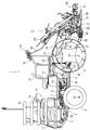
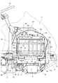
次に、図8から図15を参照しながら、ボンネット11内部の構造について説明する。ボンネット11の左右両側面のそれぞれに、上通気口201及び下通気口202を有する通気口200が開口されている。通気口200において上通気口201と下通気口202は上下に配置されている。ボンネット11の内壁に、上通気口201及び下通気口202をボンネット11内側から覆う網状部材203がボンネット11左右部位にそれぞれ取り付けられている。網状部材203は多数の孔を有し、ボンネット11の内側と外側の間で空気を流通させる。   Next, the internal structure of the bonnet 11 will be described with reference to FIGS. A vent 200 having an upper vent 201 and a lower vent 202 is opened on each of the left and right side surfaces of the bonnet 11. In the vent 200, the upper vent 201 and the lower vent 202 are arranged vertically. A mesh member 203 that covers the upper vent 201 and the lower vent 202 from the inside of the bonnet 11 is attached to the left and right parts of the bonnet 11 on the inner wall of the bonnet 11. The mesh member 203 has a large number of holes and allows air to flow between the inside and the outside of the bonnet 11.

ボンネット11内に配置されたエンジン5の右側部(一側部)に、エンジン5の動力で回転する冷却用ファン152が配置されている。冷却用ファン152はボンネット11右側部の通気口200に対向して配置される。熱交換器の一例であるエンジン5水冷用のラジエータ153が冷却用ファン152の右側方で冷却用ファン152と通気口200の間に配置されている。ラジエータ153とエンジン5との間には、冷却用ファン152を囲うファンシュラウド154が配置されている。すなわち、ファンシュラウド154の開口部に冷却用ファン152が位置され、ラジエータ153に冷却用ファン152が対峙されている。また、ラジエータ153において空気が流通するように複数の放熱用フィンが配列されたフィン部位153aは、その一部分、この実施形態では上部前寄り部位及び上部中央部位が通気口200に対峙され、その大部分が下通気口202に対峙している。   A cooling fan 152 that is rotated by the power of the engine 5 is disposed on the right side (one side) of the engine 5 disposed in the hood 11. The cooling fan 152 is disposed to face the vent hole 200 on the right side of the bonnet 11. An engine 5 water-cooling radiator 153, which is an example of a heat exchanger, is disposed between the cooling fan 152 and the vent 200 on the right side of the cooling fan 152. A fan shroud 154 that surrounds the cooling fan 152 is disposed between the radiator 153 and the engine 5. That is, the cooling fan 152 is positioned at the opening of the fan shroud 154, and the cooling fan 152 is opposed to the radiator 153. In addition, a fin portion 153a in which a plurality of heat dissipating fins are arranged so that air flows in the radiator 153, a part thereof, in this embodiment, an upper front portion and an upper central portion are opposed to the vent hole 200, and a large portion thereof. The part faces the lower vent 202.

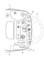
ボンネット11内では、エンジン5を取り囲む略箱枠状のボンネットフレーム155が前フレーム54とハンドルポスト67にそれぞれ連結されている。ボンネットフレーム155には、ファンシュラウド154の上部前寄り部位をボルト固定するシュラウド前ブラケット156と、ファンシュラウド154の上部後寄り部位をボルト固定するシュラウド後ブラケット157がそれぞれ固着されている。また、ラジエータ153は、右側の前部フレーム51の前寄り部位に固着された一対のラジエータブラケット158に下面両端部位がそれぞれ支持されるとともに、ファンシュラウド154にボルト締結される。これにより、ラジエータ153及びファンシュラウド154はボンネット11内で右側の前部フレーム51及びボンネットフレーム155に支持されている。   Inside the bonnet 11, a substantially box-shaped bonnet frame 155 surrounding the engine 5 is connected to the front frame 54 and the handle post 67. A front shroud bracket 156 for fixing the upper front portion of the fan shroud 154 with a bolt and a rear shroud bracket 157 for fixing the upper rear portion of the fan shroud 154 to the bonnet frame 155 are fixed. Further, the radiator 153 is supported at both lower end portions by a pair of radiator brackets 158 fixed to the front portion of the right front frame 51 and is fastened to the fan shroud 154 by bolts. Thus, the radiator 153 and the fan shroud 154 are supported by the right front frame 51 and the hood frame 155 in the hood 11.

また、一対のラジエータブラケット158のうち前側のラジエータブラケット158には、前車輪3から飛散した泥土の付着等を防止する泥除け部材159がボルト締結されている。泥除け部材159はファンシュラウド154の前下部位を覆っており、その一部分がファンシュラウド154の前側面に設けられたスリット部に挿入されている。泥除け部材159により、前車輪3から飛散した泥土のラジエータ153への付着が防止される。   Also, a mudguard member 159 that prevents adhesion of mud scattered from the front wheels 3 is bolted to the front radiator bracket 158 of the pair of radiator brackets 158. The mudguard member 159 covers the front lower part of the fan shroud 154, and a part of the mudguard member 159 is inserted into a slit provided on the front side surface of the fan shroud 154. The mudguard member 159 prevents the mud scattered from the front wheels 3 from adhering to the radiator 153.

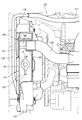
ボンネット11内で、エンジン5の上部にエアクリーナ160が配置されている。エアクリーナ160は、エンジン5の上部、例えばシリンダヘッドカバーの上面にボルト締結されたエアクリーナブラケット161上に搭載されるとともに、両端がそれぞれエアクリーナブラケット161に着脱可能に取り付けられる固定用ベルト162がエアクリーナ160外周に巻き回されて位置固定される。エアクリーナ160には、空気を取り込むための吸気管163の一端側と、吸気管163からの空気をエアクリーナ160内で浄化した後にエンジン5に供給する供給管164の一端側が接続される。供給管164の他端側はエンジン5の新気取込口、例えば吸気マニホールドに接続される。   In the bonnet 11, an air cleaner 160 is disposed above the engine 5. The air cleaner 160 is mounted on an air cleaner bracket 161 that is bolted to the upper portion of the engine 5, for example, the upper surface of the cylinder head cover, and fixing belts 162 that are detachably attached to the air cleaner bracket 161 are attached to the outer periphery of the air cleaner 160. It is wound and fixed in position. The air cleaner 160 is connected to one end side of an intake pipe 163 for taking in air and one end side of a supply pipe 164 that supplies air to the engine 5 after purifying the air from the intake pipe 163 in the air cleaner 160. The other end of the supply pipe 164 is connected to a fresh air intake port of the engine 5, for example, an intake manifold.

吸気管163の他端側はファンシュラウド154に一体成形された吸気口形成部位165に接続されている。吸気口形成部位165は、ラジエータ153収納位置の上方でファンシュラウド154のエンジン5側の面からラジエータ153側の面に向けて膨出して形成され、エンジン5側から見て凹状に形成されている。吸気口形成部位165は、略円筒形状を有し、ラジエータ153上方領域のうち後方寄りの位置に形成されている。吸気口形成部位165はその外周側面に吸気口166を備えている。吸気口166は下方、この実施形態では斜め前下方に向けて、吸気口形成部位165の円筒中心軸方向から見て輪郭のおおよそ半分が開口されて形成されている。吸気口形成部位165の略円形状の膨出端面は閉じられている。吸気口形成部位165及び吸気口166は通気口200、この実施形態では上通気口201に対峙して配置される。吸気口形成部位165にエンジン5側から吸気管163の端部が挿入されることにより、吸気口166とエアクリーナ160が吸気管163を介して流通接続される。   The other end of the intake pipe 163 is connected to an intake port forming portion 165 formed integrally with the fan shroud 154. The intake port formation portion 165 is formed to bulge from the surface on the engine 5 side of the fan shroud 154 toward the surface on the radiator 153 side above the radiator 153 storage position, and is formed in a concave shape when viewed from the engine 5 side. . The intake port forming portion 165 has a substantially cylindrical shape, and is formed at a position closer to the rear in the upper region of the radiator 153. The intake port forming portion 165 has an intake port 166 on the outer peripheral side surface thereof. The intake port 166 is formed by opening approximately half of the contour when viewed from the cylindrical central axis direction of the intake port formation portion 165 toward the lower side, in this embodiment, diagonally forward and lower. The substantially circular bulging end surface of the intake port forming portion 165 is closed. The intake port forming portion 165 and the intake port 166 are disposed so as to face the vent 200, in this embodiment, the upper vent 201. By inserting the end of the intake pipe 163 into the intake port forming portion 165 from the engine 5 side, the intake port 166 and the air cleaner 160 are circulated and connected via the intake pipe 163.

吸気口形成部位165では、吸気口166を二分割するように吸気口形成部位165の基端側部位と膨出端面を連結する外周側面部位が設けられており、この外周側面部位により膨出端面の強度が向上されている。また、吸気口形成部位165の外周側面は、ファンシュラウド154の周縁部でラジエータ153側に突出成形されたリブ部と連結されており、吸気口形成部位165の強度が向上されている。   The intake port forming portion 165 is provided with an outer peripheral side surface portion connecting the proximal end side portion of the intake port forming portion 165 and the bulging end surface so as to divide the intake port 166 into two parts. The strength of has been improved. In addition, the outer peripheral side surface of the intake port forming portion 165 is connected to a rib portion that is protruded and formed on the radiator 153 side at the peripheral portion of the fan shroud 154, so that the strength of the intake port forming portion 165 is improved.

吸気口形成部位165の膨出端面に例えば板状の遮蔽部材167が取り付けられている。遮蔽部材167は、2個の固定用ビス168により吸気口形成部位165の膨出端面の2箇所に固着されて、吸気口166と通気口200の間、この実施形態では吸気口166と上通気口201の間に配置される。遮蔽部材167は、吸気口形成部位165の膨出端面に対して前下方に突出して配置されており、右側方視で吸気口166を覆っている。吸気口形成部位165の外周側面には、固定用ビス168の取付位置に対応して、基端部位から膨出端面まで延設された2本のリブ部が外周方向へ突出成形されている。これらのリブ部は固定用ビス168の取付位置を確保するとともに吸気口形成部位165の強度を向上させている。   For example, a plate-shaped shielding member 167 is attached to the bulging end surface of the intake port forming portion 165. The shielding member 167 is fixed to two portions of the bulging end surface of the intake port forming portion 165 by two fixing screws 168, and is between the intake port 166 and the vent port 200, in this embodiment, the intake port 166 and the upper vent. Arranged between the mouths 201. The shielding member 167 is disposed so as to protrude forward and downward with respect to the bulging end surface of the intake port formation portion 165, and covers the intake port 166 when viewed from the right side. On the outer peripheral side surface of the intake port forming portion 165, two rib portions extending from the base end portion to the bulging end surface are formed so as to protrude in the outer peripheral direction corresponding to the mounting position of the fixing screw 168. These rib portions secure the mounting position of the fixing screw 168 and improve the strength of the intake port forming portion 165.

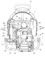
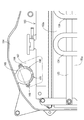
図8及び図10から図15に示すように、ボンネット11右側面の通気口200とラジエータ153の間に、作動油オイルクーラ122のコア部分124が配置されている。コア部分124は、例えば上下方向に蛇行する蛇行配管からなり、ラジエータ153の前方寄り部位から中央部位に対峙して配置される。作動油オイルクーラ122では、前後方向に延設されるとともに上下方向に互いに離間して配置された2本の取付けステー125,125がコア部分124のラジエータ153側の面に固着されている。コア部分124は、取付けステー125,125の両端部がラジエータ153の両端部位に固定されることにより、ラジエータ153に支持されている。図11に示すように、ボンネット11右側面の通気口200側から見て、コア部分124と吸気口166は水平方向でずれた位置に配置されている。   As shown in FIGS. 8 and 10 to 15, the core portion 124 of the hydraulic oil cooler 122 is disposed between the vent 200 on the right side of the bonnet 11 and the radiator 153. The core portion 124 is composed of a meandering pipe that meanders in the vertical direction, for example, and is disposed so as to face the center portion from the front portion of the radiator 153. In the hydraulic oil cooler 122, two mounting stays 125, 125 that extend in the front-rear direction and are spaced apart from each other in the vertical direction are fixed to the surface of the core portion 124 on the radiator 153 side. The core portion 124 is supported by the radiator 153 by fixing both ends of the mounting stays 125, 125 to both ends of the radiator 153. As shown in FIG. 11, the core portion 124 and the air inlet 166 are disposed at positions shifted in the horizontal direction when viewed from the vent 200 side on the right side surface of the bonnet 11.

図10から図13に示すように、作動油オイルクーラ122のコア部分124の作動油入口側は、作動油送り配管126及び作動油送りチューブ127を介して油圧無段変速機40のチャージドレン継手121に接続される。コア部分124の作動油出口側は、作動油戻し配管128及び作動油戻しチューブ129を介してミッションケース6の作動油戻し継手123に接続される。チャージポンプ91(図7参照)の作動により、ミッションケース6内部の作動油は、油圧無段変速機40、チャージドレン継手121、作動油送りチューブ127、作動油送り配管126、作動油オイルクーラ122のコア部分124、作動油戻し配管128及び作動油戻しチューブ129を介して循環冷却される。   As shown in FIGS. 10 to 13, the hydraulic oil inlet side of the core portion 124 of the hydraulic oil cooler 122 is connected to the charge drain joint of the hydraulic continuously variable transmission 40 via the hydraulic oil feed pipe 126 and the hydraulic oil feed tube 127. 121 is connected. The hydraulic oil outlet side of the core portion 124 is connected to the hydraulic oil return joint 123 of the mission case 6 via the hydraulic oil return pipe 128 and the hydraulic oil return tube 129. By the operation of the charge pump 91 (see FIG. 7), the hydraulic oil in the transmission case 6 is converted into the hydraulic continuously variable transmission 40, the charge drain joint 121, the hydraulic oil feed tube 127, the hydraulic oil feed pipe 126, and the hydraulic oil cooler 122. Are circulated and cooled through the core portion 124, the hydraulic oil return pipe 128, and the hydraulic oil return tube 129.

この実施形態の乗用型田植機1は、ボンネット11の右側面に設けられた通気口200に対峙してエンジン5の吸気口166が配置されるとともに、吸気口166と通気口200の間に通気口200側から見て吸気口166を覆う遮蔽部材167を備えている。これにより、ボンネット11に右側方から水がかかる状況であっても遮蔽部材167によって吸気口166への水の浸入が阻止され、吸気管163やエアクリーナ160、供給管164などのエンジン5の吸気経路への吸気口166からの水の浸入を防止することができる。   In the riding-type rice transplanter 1 of this embodiment, the air intake 166 of the engine 5 is disposed opposite to the air vent 200 provided on the right side surface of the bonnet 11, and the air vent is provided between the air intake 166 and the air vent 200. A shielding member 167 that covers the intake port 166 when viewed from the mouth 200 side is provided. Thereby, even if the bonnet 11 is in a state where water is applied from the right side, the shielding member 167 prevents water from entering the intake port 166, and the intake path of the engine 5 such as the intake pipe 163, the air cleaner 160, and the supply pipe 164. It is possible to prevent water from entering from the air inlet 166.

また、この実施形態の乗用型田植機1では、冷却用ファン152を囲うファンシュラウド154に吸気口166が一体成形されるとともに、ファンシュラウド154に遮蔽部材167が取り付けられている。したがって、遮蔽部材167を支持するための部材をファンシュラウド154とは別途に設ける必要がないので、部品点数や製造コストを低減できるとともに、遮蔽部材167を簡便に取付けできる。   Further, in the riding type rice transplanter 1 of this embodiment, the air inlet 166 is integrally formed with the fan shroud 154 surrounding the cooling fan 152, and the shielding member 167 is attached to the fan shroud 154. Therefore, since it is not necessary to provide a member for supporting the shielding member 167 separately from the fan shroud 154, the number of parts and manufacturing cost can be reduced, and the shielding member 167 can be easily attached.

また、この実施形態の乗用型田植機1では、吸気口166は斜め前下方に向けて開口されている。したがって、ボンネット11右側方から通気口200に向かって水がかかる状況であっても、遮蔽部材167による吸気口166への水の侵入防止の効果に加えて、より確実に吸気口166への水の浸入を防止できる。   Moreover, in the riding type rice transplanter 1 of this embodiment, the intake port 166 is opened diagonally forward and downward. Therefore, even in a situation where water is applied from the right side of the bonnet 11 toward the vent hole 200, in addition to the effect of preventing water from entering the intake port 166 by the shielding member 167, the water to the intake port 166 is more reliably secured. Can be prevented.

また、この実施形態の乗用型田植機1では、作動油オイルクーラ122のコア部分124がボンネット11右側面の通気口200とラジエータ153の間に配置され、吸気口166がラジエータ153の上方に配置されている。さらに、ボンネット11右側面の通気口200側から見て、コア部分124と吸気口166が水平方向でずれた位置に配置されている。したがって、作動油オイルクーラ122、特にコア部分124に留まって発生する熱が吸気口166に直接吸引されないようにすることができる。これにより、吸気口166から取り込まれる燃焼用空気に関し、作動油オイルクーラ122の発熱に起因する温度上昇を抑制でき、ひいてはエンジン5の出力の低下を抑制できる。   Further, in the riding type rice transplanter 1 of this embodiment, the core portion 124 of the hydraulic oil cooler 122 is disposed between the vent 200 on the right side of the bonnet 11 and the radiator 153, and the intake port 166 is disposed above the radiator 153. Has been. Further, the core portion 124 and the air inlet 166 are disposed at positions shifted in the horizontal direction when viewed from the vent 200 side on the right side surface of the bonnet 11. Therefore, the heat generated by staying in the hydraulic oil cooler 122, particularly the core portion 124, can be prevented from being directly sucked into the intake port 166. Thereby, regarding the combustion air taken in from the intake port 166, the temperature rise caused by the heat generation of the hydraulic oil cooler 122 can be suppressed, and consequently the decrease in the output of the engine 5 can be suppressed.

さらに、ボンネット11右側面の通気口200は、上通気口201と下通気口202に上下に分割されており、吸気口166は上通気口201に対峙し、コア部分124は下通気口202に対峙している。また、ラジエータ153において空気が流通するフィン部位153aは、フィン部位153aの上部前寄り部位及び上部中央部位が通気口200に対峙され、その大部分が下通気口202に対峙している。また、冷却用ファン152の作動によりボンネット11右側面の通気口200からボンネット11内部に流れ込む空気は、ラジエータ153のフィン部位153a及びファンシュラウド154を介してエンジン5側へ流通する。したがって、ボンネット11右側面の上通気口201から左斜め下方のフィン部位153aへ向かう空気の流れができるので、ラジエータ153上方に吸気口166が配置されていることにより、作動油オイルクーラ122で放射される熱が吸気口166に直接吸引されるのを防止できる。   Further, the air vent 200 on the right side of the bonnet 11 is divided into an upper air vent 201 and a lower air vent 202, and the air inlet 166 faces the upper air vent 201, and the core portion 124 faces the lower air vent 202. Confronted. Further, in the fin portion 153 a through which air flows in the radiator 153, the upper front portion and the upper central portion of the fin portion 153 a are opposed to the vent 200, and most of the fin portion 153 a is opposed to the lower vent 202. Further, the air flowing into the hood 11 from the vent 200 on the right side surface of the bonnet 11 by the operation of the cooling fan 152 circulates to the engine 5 side through the fin portion 153a of the radiator 153 and the fan shroud 154. Accordingly, air can flow from the upper vent 201 on the right side surface of the bonnet 11 toward the fin portion 153a obliquely downward to the left, so that the intake port 166 is disposed above the radiator 153, thereby radiating at the hydraulic oil cooler 122. It is possible to prevent the generated heat from being directly sucked into the intake port 166.

本願発明は、前述の実施形態に限らず、様々な態様に具体化できる。各部の構成は図示の実施形態に限定されるものではなく、本願発明の趣旨を逸脱しない範囲で種々変更が可能である。例えば、本願発明の作業車両は、乗用型田植機のみならず、例えば農業用トラクターや土木建設用のホイルローダなど、他の作業車両にも適用できる。   The present invention is not limited to the above-described embodiment, and can be embodied in various forms. The configuration of each part is not limited to the illustrated embodiment, and various modifications can be made without departing from the spirit of the present invention. For example, the work vehicle of the present invention can be applied not only to a riding type rice transplanter but also to other work vehicles such as an agricultural tractor and a wheel loader for civil engineering construction.

1 乗用型田植機(作業車両)
2 走行機体
5 エンジン
11 ボンネット
122 作動油オイルクーラ
124 コア部分
152 冷却用ファン
153 ラジエータ
154 ファンシュラウド
166 吸気口
167 遮蔽部材
200 通気口
1 Passenger rice transplanter (work vehicle)
2 traveling machine body 5 engine 11 bonnet 122 hydraulic oil cooler 124 core portion 152 cooling fan 153 radiator 154 fan shroud 166 air inlet 167 shielding member 200 air vent

Claims (4)

走行機体に搭載されたエンジンと、エンジンの一側部に配置された冷却用ファンと、エンジンを覆うとともに冷却用ファンに対向する側面に通気口を有するボンネットを備えた作業車両であって、
前記エンジンの吸気口が前記通気口に対峙して配置されるとともに、前記吸気口と前記通気口の間に前記通気口側から見て前記吸気口を覆う遮蔽部材を備えた作業車両。
An engine mounted on a traveling machine, a cooling fan disposed on one side of the engine, and a work vehicle including a bonnet that covers the engine and has a vent on a side facing the cooling fan,
A work vehicle provided with a shielding member that is disposed so that an intake port of the engine faces the vent and covers the intake port as viewed from the vent side between the intake port and the vent.
前記冷却用ファンを囲うファンシュラウドに前記吸気口が一体成形されるとともに、前記ファンシュラウドに前記遮蔽部材が取り付けられている請求項1に記載の作業車両。   The work vehicle according to claim 1, wherein the intake port is integrally formed with a fan shroud surrounding the cooling fan, and the shielding member is attached to the fan shroud. 前記吸気口は下方に向けて開口されている請求項1又は2に記載の作業車両。   The work vehicle according to claim 1, wherein the intake port is opened downward. 前記冷却用ファンと前記通気口の間にラジエータが配置される構成であって、
作動油オイルクーラのコア部分が前記通気口と前記ラジエータの間に配置され、前記吸気口が前記ラジエータの上方に配置されており、前記通気口側から見て前記コア部分と前記吸気口が水平方向でずれた位置に配置されている請求項1から3のいずれか一項に記載の作業車両。
A radiator is disposed between the cooling fan and the vent hole,
The core portion of the hydraulic oil cooler is disposed between the vent and the radiator, the intake port is disposed above the radiator, and the core portion and the intake port are horizontal when viewed from the vent side. The work vehicle according to any one of claims 1 to 3, wherein the work vehicle is disposed at a position shifted in a direction.
JP2016072276A 2016-03-31 2016-03-31 Work vehicle Pending JP2017178246A (en)

Priority Applications (1)

Application Number Priority Date Filing Date Title
JP2016072276A JP2017178246A (en) 2016-03-31 2016-03-31 Work vehicle

Applications Claiming Priority (1)

Application Number Priority Date Filing Date Title
JP2016072276A JP2017178246A (en) 2016-03-31 2016-03-31 Work vehicle

Publications (1)

Publication Number Publication Date
JP2017178246A true JP2017178246A (en) 2017-10-05

Family

ID=60008195

Family Applications (1)

Application Number Title Priority Date Filing Date
JP2016072276A Pending JP2017178246A (en) 2016-03-31 2016-03-31 Work vehicle

Country Status (1)

Country Link
JP (1) JP2017178246A (en)

Cited By (2)

* Cited by examiner, † Cited by third party
Publication number Priority date Publication date Assignee Title
JP7090677B2 (en) 2020-10-26 2022-06-24 株式会社クボタ Passenger work vehicle
US11520021B2 (en) 2019-03-19 2022-12-06 Kabushiki Kaisha Toshiba Light receiving device and range finding device including a switch circuit which re-arranges the order of signals output from a light receiver

Citations (7)

* Cited by examiner, † Cited by third party
Publication number Priority date Publication date Assignee Title
JPS56147124U (en) * 1980-04-08 1981-11-06
JPS6076523U (en) * 1983-10-31 1985-05-29 井関農機株式会社 Air intake of air cleaner in mobile agricultural machinery
JP2003118399A (en) * 2001-10-16 2003-04-23 Seirei Ind Co Ltd Engine related structure for combine harvester
US20060086549A1 (en) * 2004-10-25 2006-04-27 Deere & Company, A Delaware Corporation Integrated fan shroud air intake system
JP2011189904A (en) * 2010-03-16 2011-09-29 Yanmar Co Ltd Working vehicle
JP2015223870A (en) * 2014-05-26 2015-12-14 株式会社クボタ Work machine
JP2016032969A (en) * 2014-07-31 2016-03-10 株式会社クボタ Mobile vehicle

Patent Citations (7)

* Cited by examiner, † Cited by third party
Publication number Priority date Publication date Assignee Title
JPS56147124U (en) * 1980-04-08 1981-11-06
JPS6076523U (en) * 1983-10-31 1985-05-29 井関農機株式会社 Air intake of air cleaner in mobile agricultural machinery
JP2003118399A (en) * 2001-10-16 2003-04-23 Seirei Ind Co Ltd Engine related structure for combine harvester
US20060086549A1 (en) * 2004-10-25 2006-04-27 Deere & Company, A Delaware Corporation Integrated fan shroud air intake system
JP2011189904A (en) * 2010-03-16 2011-09-29 Yanmar Co Ltd Working vehicle
JP2015223870A (en) * 2014-05-26 2015-12-14 株式会社クボタ Work machine
JP2016032969A (en) * 2014-07-31 2016-03-10 株式会社クボタ Mobile vehicle

Cited By (2)

* Cited by examiner, † Cited by third party
Publication number Priority date Publication date Assignee Title
US11520021B2 (en) 2019-03-19 2022-12-06 Kabushiki Kaisha Toshiba Light receiving device and range finding device including a switch circuit which re-arranges the order of signals output from a light receiver
JP7090677B2 (en) 2020-10-26 2022-06-24 株式会社クボタ Passenger work vehicle

Similar Documents

Publication Publication Date Title
US7559295B2 (en) Cooling structure for a work vehicle
JP6226816B2 (en) Working machine
JP6726089B2 (en) Work vehicle
JP3862674B2 (en) Ride type transplanter
JP2017178246A (en) Work vehicle
JP3515705B2 (en) Mower
JP6612175B2 (en) Working machine and rice transplanter
JP2003072602A (en) Moving agricultural machine
JP2020023317A (en) Work machine
JP2018172083A (en) Paddy field work machine
JP5008109B2 (en) Rice transplanter
JP3599479B2 (en) Riding transplanter
JP4739610B2 (en) Mobile farm machine
WO2022168909A1 (en) Cooling apparatus for work vehicle and work vehicle
JP4073587B2 (en) Mobile farm machine
JP2003153616A (en) Rice transplanter
JP5513363B2 (en) Working machine
JP3934187B2 (en) Traveling agricultural machine
JP2008087490A (en) Working vehicle
JP6925256B2 (en) Work platform
JP2004141098A (en) Body frame structure of sulky type rice transplanter
JP2012126337A (en) Traveling vehicle
JP2005067327A (en) Agricultural tractor
KR100963485B1 (en) Apparatus for cooling engine and rice-transplanter with the same
JP2010031574A (en) Working machine

Legal Events

Date Code Title Description
A621 Written request for application examination

Free format text: JAPANESE INTERMEDIATE CODE: A621

Effective date: 20180205

A977 Report on retrieval

Free format text: JAPANESE INTERMEDIATE CODE: A971007

Effective date: 20181220

A131 Notification of reasons for refusal

Free format text: JAPANESE INTERMEDIATE CODE: A131

Effective date: 20181226

A02 Decision of refusal

Free format text: JAPANESE INTERMEDIATE CODE: A02

Effective date: 20190703