JP2017163508A - Master slave control system, method for controlling master slave control system, information processing program, and recording medium - Google Patents
Master slave control system, method for controlling master slave control system, information processing program, and recording medium Download PDFInfo
- Publication number
- JP2017163508A JP2017163508A JP2016048958A JP2016048958A JP2017163508A JP 2017163508 A JP2017163508 A JP 2017163508A JP 2016048958 A JP2016048958 A JP 2016048958A JP 2016048958 A JP2016048958 A JP 2016048958A JP 2017163508 A JP2017163508 A JP 2017163508A
- Authority
- JP
- Japan
- Prior art keywords
- identification information
- communication port
- device communication
- control system
- unit
- Prior art date
- Legal status (The legal status is an assumption and is not a legal conclusion. Google has not performed a legal analysis and makes no representation as to the accuracy of the status listed.)
- Pending
Links
- 238000000034 method Methods 0.000 title claims abstract description 97
- 230000010365 information processing Effects 0.000 title claims description 7
- 230000006854 communication Effects 0.000 claims abstract description 575
- 238000004891 communication Methods 0.000 claims abstract description 575
- 238000012795 verification Methods 0.000 claims description 58
- 238000012545 processing Methods 0.000 abstract description 106
- 230000005540 biological transmission Effects 0.000 description 22
- 230000000694 effects Effects 0.000 description 13
- 238000010586 diagram Methods 0.000 description 10
- 230000002159 abnormal effect Effects 0.000 description 8
- 230000006870 function Effects 0.000 description 8
- 230000005856 abnormality Effects 0.000 description 2
- 241000699670 Mus sp. Species 0.000 description 1
- 230000007175 bidirectional communication Effects 0.000 description 1
- 230000007547 defect Effects 0.000 description 1
- 238000001514 detection method Methods 0.000 description 1
- 230000006866 deterioration Effects 0.000 description 1
- 239000004973 liquid crystal related substance Substances 0.000 description 1
- 238000012423 maintenance Methods 0.000 description 1
- 238000012986 modification Methods 0.000 description 1
- 230000004048 modification Effects 0.000 description 1
- 230000001902 propagating effect Effects 0.000 description 1
- 239000004065 semiconductor Substances 0.000 description 1
Images


Classifications
-
- H—ELECTRICITY
- H04—ELECTRIC COMMUNICATION TECHNIQUE
- H04L—TRANSMISSION OF DIGITAL INFORMATION, e.g. TELEGRAPHIC COMMUNICATION
- H04L41/00—Arrangements for maintenance, administration or management of data switching networks, e.g. of packet switching networks
- H04L41/12—Discovery or management of network topologies
-
- G—PHYSICS
- G05—CONTROLLING; REGULATING
- G05B—CONTROL OR REGULATING SYSTEMS IN GENERAL; FUNCTIONAL ELEMENTS OF SUCH SYSTEMS; MONITORING OR TESTING ARRANGEMENTS FOR SUCH SYSTEMS OR ELEMENTS
- G05B19/00—Programme-control systems
- G05B19/02—Programme-control systems electric
- G05B19/04—Programme control other than numerical control, i.e. in sequence controllers or logic controllers
- G05B19/042—Programme control other than numerical control, i.e. in sequence controllers or logic controllers using digital processors
-
- H—ELECTRICITY
- H04—ELECTRIC COMMUNICATION TECHNIQUE
- H04L—TRANSMISSION OF DIGITAL INFORMATION, e.g. TELEGRAPHIC COMMUNICATION
- H04L67/00—Network arrangements or protocols for supporting network services or applications
- H04L67/50—Network services
- H04L67/60—Scheduling or organising the servicing of application requests, e.g. requests for application data transmissions using the analysis and optimisation of the required network resources
-
- G—PHYSICS
- G05—CONTROLLING; REGULATING
- G05B—CONTROL OR REGULATING SYSTEMS IN GENERAL; FUNCTIONAL ELEMENTS OF SUCH SYSTEMS; MONITORING OR TESTING ARRANGEMENTS FOR SUCH SYSTEMS OR ELEMENTS
- G05B2219/00—Program-control systems
- G05B2219/20—Pc systems
- G05B2219/22—Pc multi processor system
- G05B2219/2231—Master slave
-
- H—ELECTRICITY
- H04—ELECTRIC COMMUNICATION TECHNIQUE
- H04L—TRANSMISSION OF DIGITAL INFORMATION, e.g. TELEGRAPHIC COMMUNICATION
- H04L41/00—Arrangements for maintenance, administration or management of data switching networks, e.g. of packet switching networks
- H04L41/04—Network management architectures or arrangements
- H04L41/045—Network management architectures or arrangements comprising client-server management architectures
-
- H—ELECTRICITY
- H04—ELECTRIC COMMUNICATION TECHNIQUE
- H04L—TRANSMISSION OF DIGITAL INFORMATION, e.g. TELEGRAPHIC COMMUNICATION
- H04L67/00—Network arrangements or protocols for supporting network services or applications
- H04L67/2866—Architectures; Arrangements
- H04L67/30—Profiles
- H04L67/303—Terminal profiles
Abstract
Description
本発明は、マスタ装置と、前記マスタ装置とネットワークを介して接続されるスレーブ装置と、を含むマスタースレーブ制御システムに関する。 The present invention relates to a master-slave control system including a master device and a slave device connected to the master device via a network.
従来、マスタ装置と、前記マスタ装置とネットワークを介して接続されるスレーブ装置と、を含むマスタースレーブ制御システムが知られている。 Conventionally, a master-slave control system including a master device and a slave device connected to the master device via a network is known.
例えば、下掲の特許文献1には、IOユニットに接続されるべきフィールド機器の機器ID等を表示する装置が記載されている。
For example,
しかしながら、上述のような従来技術は、IOユニットに接続されるべきフィールド機器を特定する情報を数値としてのみ表示するため、ユーザが、前記通信ポートに接続させるべきデバイスを把握するのが困難であるという問題がある。 However, since the prior art as described above displays only information indicating the field device to be connected to the IO unit as a numerical value, it is difficult for the user to grasp the device to be connected to the communication port. There is a problem.
本発明は、前記の問題点に鑑みてなされたものであり、その目的は、ユーザが、前記通信ポートに接続させるべきデバイスを容易に知ることのできるマスタースレーブ制御システム等を実現することにある。 The present invention has been made in view of the above problems, and an object of the present invention is to realize a master-slave control system or the like that allows a user to easily know a device to be connected to the communication port. .
上記の課題を解決するために、本発明に係るマスタースレーブ制御システムは、マスタ装置であるコントローラと、前記コントローラとネットワークを介して接続され、デバイスが接続される通信ポートを備えるスレーブ装置と、を含むマスタースレーブ制御システムであって、前記通信ポートに接続することが予定されているデバイスの識別情報を含む構成情報を記憶した記憶部と、前記通信ポートに接続されたデバイスから前記デバイスの識別情報を取得する取得部と、前記取得部の取得した識別情報と、前記構成情報に含まれる識別情報とを照合する照合部と、前記照合部により、前記取得部の取得した識別情報と、前記構成情報に含まれる識別情報とが一致しないと判定されると、前記通信ポートに接続することが予定されているデバイスの形式名をユーザに通知する通知部と、を備えることを特徴としている。 In order to solve the above problems, a master-slave control system according to the present invention includes a controller that is a master device, and a slave device that is connected to the controller via a network and includes a communication port to which a device is connected. A master-slave control system including a storage unit storing configuration information including identification information of a device scheduled to be connected to the communication port, and identification information of the device from the device connected to the communication port An acquisition unit that acquires the identification information acquired by the acquisition unit and the identification information included in the configuration information, the identification information acquired by the acquisition unit by the verification unit, and the configuration If it is determined that the identification information included in the information does not match, the device that is scheduled to be connected to the communication port is used. It is characterized by comprising a notification unit that notifies the format name of the chair to the user.
前記の構成によれば、前記通知部は、前記通信ポートに接続された前記デバイスの識別情報と、前記通信ポートに接続することが予定されているデバイスの識別情報とが一致しないと判定されると、前記通信ポートに接続することが予定されているデバイスの形式名をユーザに通知する。 According to the above configuration, the notification unit determines that the identification information of the device connected to the communication port does not match the identification information of the device scheduled to be connected to the communication port. And the user is notified of the model name of the device that is scheduled to be connected to the communication port.
したがって、前記マスタースレーブ制御システムが、前記通信ポートに接続することが予定されているデバイスの形式名をユーザに通知することにより、ユーザは、前記通信ポートに接続させるべきデバイスを容易に知ることができるという効果を奏する。 Therefore, the master-slave control system notifies the user of the model name of the device that is scheduled to be connected to the communication port, so that the user can easily know the device to be connected to the communication port. There is an effect that can be done.
本発明に係るマスタースレーブ制御システムについて、前記構成情報に含まれる識別情報は、ユーザにより予め登録された情報であってもよい。 In the master-slave control system according to the present invention, the identification information included in the configuration information may be information registered in advance by a user.
前記の構成によれば、前記マスタースレーブ制御システムは、ユーザが予め登録した前記構成情報を用いて、前記通信ポートに接続することが予定されているデバイスの形式名をユーザに通知することができるという効果を奏する。 According to the above configuration, the master slave control system can notify the user of the model name of the device that is scheduled to be connected to the communication port, using the configuration information registered in advance by the user. There is an effect.
本発明に係るマスタースレーブ制御システムについて、前記照合部は、前記コントローラ、前記スレーブ装置、前記コントローラに接続している外部装置、および、前記スレーブ装置に接続している外部装置の少なくとも1つに備えられていてもよい。 In the master-slave control system according to the present invention, the verification unit is provided in at least one of the controller, the slave device, an external device connected to the controller, and an external device connected to the slave device. It may be done.
前記の構成によれば、前記照合部は、前記コントローラ、前記スレーブ装置、前記コントローラに接続している外部装置、および、前記スレーブ装置に接続している外部装置の少なくとも1つに備えられる。 According to the above configuration, the verification unit is provided in at least one of the controller, the slave device, an external device connected to the controller, and an external device connected to the slave device.
したがって、前記マスタースレーブ制御システムは、前記コントローラ、前記スレーブ装置、前記コントローラに接続している外部装置、および、前記スレーブ装置に接続している外部装置の少なくとも1つにおいて、前記取得部により取得可能な識別情報と、前記構成情報に含まれる識別情報とを照合し、照合結果(特に、接続の予定されているデバイスの形式名)を表示することができるという効果を奏する。 Therefore, the master-slave control system can be acquired by the acquisition unit in at least one of the controller, the slave device, an external device connected to the controller, and an external device connected to the slave device. It is possible to collate the identification information with the identification information included in the configuration information, and display the collation result (particularly, the model name of the device scheduled to be connected).
本発明に係るマスタースレーブ制御システムについて、前記通知部は、前記通信ポートに接続することが予定されているデバイスの形式名を、前記コントローラ、前記スレーブ装置、前記コントローラに接続している外部装置、および、前記スレーブ装置に接続している外部装置の少なくとも1つに表示させてもよい。 For the master-slave control system according to the present invention, the notification unit includes the device model name scheduled to be connected to the communication port, the controller, the slave device, an external device connected to the controller, And it may be displayed on at least one of the external devices connected to the slave device.
前記の構成によれば、前記マスタースレーブ制御システムは、前記通信ポートに接続することが予定されているデバイスの形式名を、前記コントローラ、前記スレーブ装置、前記コントローラに接続している外部装置、および、前記スレーブ装置に接続している外部装置の少なくとも1つに表示させることにより、ユーザに通知することができるという効果を奏する。 According to the above configuration, the master-slave control system is configured such that the controller, the slave device, the external device connected to the controller, and the type name of the device scheduled to be connected to the communication port, and By displaying on at least one of the external devices connected to the slave device, the user can be notified.
本発明に係るマスタースレーブ制御システムについて、前記照合部は、前記スレーブ装置に備えられ、前記通知部は、前記通信ポートに接続することが予定されているデバイスの形式名を、前記コントローラに接続している外部装置に表示させてもよい。 In the master-slave control system according to the present invention, the verification unit is provided in the slave device, and the notification unit connects a model name of a device scheduled to be connected to the communication port to the controller. May be displayed on an external device.
前記の構成によれば、前記スレーブ装置が前記記憶部および前記取得部を備えている場合、前記スレーブ装置は、前記照合を実行するための情報を他の装置から取得する必要がない。つまり、本発明に係るマスタースレーブ制御システムにおいて、前記スレーブ装置が前記記憶部および前記取得部を備えている場合、前記スレーブ装置は、他の装置から別途、前記通信ポートに接続することが予定されているデバイスの識別情報、および、前記通信ポートに接続されたデバイスの識別情報を取得することなく、前記照合を実行することができる。本発明に係るマスタースレーブ制御システムにおいて、「前記スレーブ装置が、他の装置から別途、前記通信ポートに接続することが予定されているデバイスの識別情報、および、前記通信ポートに接続されたデバイスの識別情報を取得する」ためのプログラム等を用意せずとも、前記スレーブ装置は前記照合を実行する。 According to the above configuration, when the slave device includes the storage unit and the acquisition unit, the slave device does not need to acquire information for executing the collation from another device. That is, in the master-slave control system according to the present invention, when the slave device includes the storage unit and the acquisition unit, the slave device is scheduled to be connected to the communication port separately from another device. The collation can be executed without acquiring the identification information of the connected device and the identification information of the device connected to the communication port. In the master-slave control system according to the present invention, “the slave device is separately identified from another device as identification information of a device that is scheduled to be connected to the communication port, and the device connected to the communication port Even without preparing a program or the like for “acquiring identification information”, the slave device performs the verification.
したがって、本発明に係るマスタースレーブ制御システムにおいて、前記プログラム等の作成・調整のためのユーザ作業が不要になり、ユーザの負担を低減することができるという効果を奏する。また、前記スレーブ装置と他の装置との間の情報の遣り取りが不要となるため、本発明に係るマスタースレーブ制御システムの立ち上がり時間を短縮することができるという効果を奏する。 Therefore, the master-slave control system according to the present invention eliminates the need for user work for creating / adjusting the program and the like, thereby reducing the burden on the user. In addition, since there is no need to exchange information between the slave device and another device, the rise time of the master-slave control system according to the present invention can be shortened.
また、例えばHMIである前記外部装置に、前記通信ポートに接続することが予定されているデバイスの形式名を表示させることにより、ユーザにとって見易い表示とすることができるという効果を奏する。 Further, for example, by displaying the format name of the device that is scheduled to be connected to the communication port on the external device that is an HMI, it is possible to achieve an easy-to-view display for the user.
本発明に係るマスタースレーブ制御システムについて、前記スレーブ装置と前記デバイスとはIO−Link(登録商標)で通信してもよい。 In the master-slave control system according to the present invention, the slave device and the device may communicate with each other by IO-Link (registered trademark).
前記の構成によれば、前記スレーブスレーブ制御システムは、前記デバイスとIO−Link(登録商標)で通信することができるという効果を奏する。 According to the said structure, the said slave slave control system has an effect that it can communicate with the said device by IO-Link (trademark).
上記の課題を解決するために、本発明に係るマスタースレーブ制御システムの制御方法は、マスタ装置であるコントローラと、前記コントローラとネットワークを介して接続されるスレーブ装置と、を含むマスタースレーブ制御システムにおける前記スレーブ装置の通信ポートに接続することが予定されているデバイスの識別情報を含む構成情報を記憶した記憶部を備えるコンピュータが、前記通信ポートに接続されたデバイスから前記デバイスの識別情報を取得する取得ステップと、前記取得ステップにて取得した識別情報と、前記構成情報に含まれる識別情報とを照合する照合ステップと、前記照合ステップにて、前記取得ステップにて取得した識別情報と、前記構成情報に含まれる識別情報とが一致しないと判定すると、前記通信ポートに接続することが予定されているデバイスの形式名をユーザに通知する通知ステップと、を実行することを特徴としている。 In order to solve the above problems, a control method of a master-slave control system according to the present invention is a master-slave control system including a controller that is a master device and a slave device that is connected to the controller via a network. A computer having a storage unit storing configuration information including identification information of a device scheduled to be connected to the communication port of the slave apparatus acquires the identification information of the device from the device connected to the communication port An acquisition step; a collation step for collating the identification information acquired in the acquisition step with the identification information included in the configuration information; the identification information acquired in the acquisition step in the verification step; and the configuration If it is determined that the identification information included in the information does not match, the communication port That connection is characterized by performing the notification step for notifying the user format name of the device which is scheduled, to.
前記の方法によれば、前記通知ステップは、前記通信ポートに接続されたデバイスの識別情報と、前記通信ポートに接続することが予定されているデバイスの識別情報とが一致しないと判定されると、前記通信ポートに接続することが予定されているデバイスの形式名をユーザに通知する。 According to the method, when the notification step determines that the identification information of the device connected to the communication port does not match the identification information of the device scheduled to be connected to the communication port. The user is notified of the model name of the device that is scheduled to be connected to the communication port.
したがって、前記マスタースレーブ制御システムが、前記通信ポートに接続することが予定されているデバイスの形式名をユーザに通知することにより、ユーザは、前記通信ポートに接続させるべきデバイスを容易に知ることができるという効果を奏する。 Therefore, the master-slave control system notifies the user of the model name of the device that is scheduled to be connected to the communication port, so that the user can easily know the device to be connected to the communication port. There is an effect that can be done.
本発明は、マスタ装置であるコントローラと、前記コントローラとネットワークを介して接続され、デバイスが接続される通信ポートを備えるスレーブ装置と、を含むマスタースレーブ制御システムにおいて、ユーザは、前記通信ポートに接続させるべきデバイスを容易に知ることができるという効果を奏する。 The present invention provides a master-slave control system including a controller that is a master device and a slave device that is connected to the controller via a network and includes a communication port to which a device is connected. There is an effect that the device to be made can be easily known.
〔実施形態1〕
以下、本発明の実施形態1について図1から図10に基づいて詳細に説明する。図中同一または相当部分には同一符号を付してその説明は繰返さない。本発明の一態様に係る制御システム1(マスタースレーブ制御システム)の概要を、図2を用いて説明する。
Hereinafter,
(実施形態1の制御システムの概要)
図2は、制御システム1の概要を示す図である。図2に示すように、制御システム1は、上位コントローラ40(コントローラ)と、上位コントローラ40にフィールドネットワーク50(上位バス、すなわち、上位通信ネットワーク)を介して接続される、1つ以上のデバイス通信管理ユニット10と、を含む。図2に示す例では、デバイス通信管理ユニット10(A)およびデバイス通信管理ユニット10(B)が、フィールドネットワーク50を介して、上位コントローラ40に接続されている。なお、以下の説明において、デバイス通信管理ユニット10(A)およびデバイス通信管理ユニット10(B)の各々を特に区別する必要がない場合は、単に「デバイス通信管理ユニット10」と称する。
(Outline of the control system of Embodiment 1)
FIG. 2 is a diagram showing an outline of the
制御システム1は、マスタ装置としての上位コントローラ40と、マスタ装置にネットワーク(フィールドネットワーク50)を介して接続される1つ以上のスレーブ装置としてのデバイス通信管理ユニット10とを含むマスタースレーブ制御システムである。上位コントローラ40は、フィールドネットワーク50を介したデータ伝送を管理しているという意味で「マスタ装置」と呼ばれ、一方、デバイス通信管理ユニット10は「スレーブ装置」と呼ばれる。
The
制御システム1において、デバイス通信管理ユニット10には、デバイス通信ケーブル30を介して、1つ以上のデバイス20が接続される。図2に示す例では、デバイス20(1)、20(2)、20(3)、・・・、20(n)が、デバイス通信ケーブル30を介して、デバイス通信管理ユニット10に接続されている。なお、以下の説明において、デバイス20(1)、20(2)、20(3)、・・・、20(n)の各々を特に区別する必要がない場合は、単に「デバイス20」と称する。
In the
上位コントローラ40は、例えば、PLC(Programmable Logic Controller)であり、制御システム1における、フィールドネットワーク50を介したデータ伝送を管理するマスタ装置である。マスタ装置としての上位コントローラ40に接続されるスレーブ装置としては、デバイス通信管理ユニット10以外にも、フィールドネットワーク50に直接接続される、サーボドライバ(不図示)なども含み得る。さらに、フィールドネットワーク50に複数の上位コントローラ40が接続される場合には、いずれか1つの上位コントローラ40がマスタ装置となり、残りの上位コントローラ40がスレーブ装置になる場合もある。さらにあるいは、上位コントローラ40およびデバイス通信管理ユニット10のいずれとも異なる制御主体がマスタ装置になってもよい。すなわち、「マスタ装置」および「スレーブ装置」は、フィールドネットワーク50上のデータ伝送の制御機能に着目して定義されるものであり、各装置間でどのような情報が送受信されるかについては、特に限定されない。
The
上位コントローラ40は、制御システム1の全体の制御を行う。具体的には、上位コントローラ40は、センサなどの入力機器であるデバイス20からの情報を入力データとして取得し、予め組み込まれたユーザプログラムに従って、係る取得した入力データを用いて演算処理を実行する。そして、上位コントローラ40は、前記演算処理を実行して、アクチュエータなどの出力機器であるデバイス20への制御内容を決定し、その制御内容に対応する制御データをデバイス20へ出力する。
The
フィールドネットワーク50は、上位コントローラ40が受信し、または上位コントローラ40が送信する各種データを伝送し、例えば、EtherCAT(登録商標)、PROFINET(登録商標)、MECHATROLINK(登録商標)−III、Powerlink、SERCOS(登録商標)−III、CIP Motionである。また、フィールドネットワーク50は、例えば、EtherNet/IP(登録商標)、DeviceNet、CompoNet(登録商標)などであってもよい。なお、以下では、フィールドネットワーク50上をデータフレームが順次転送されることで、上位コントローラ40とデバイス通信管理ユニット10との間、または、デバイス通信管理ユニット10(A)とデバイス通信管理ユニット10(B)との間でデータが送受信される制御システム1について説明を行う。また、以下の説明においては、フィールドネットワーク50を、下位の通信ネットワークであるデバイス通信ケーブル30を介した通信と対比させるために、「上位バス(上位通信ネットワーク)」と呼ぶことがある。さらに、デバイス通信ケーブル30上を伝搬するデータフレームと区別するために、フィールドネットワーク50上のデータフレームを「上位データフレーム」とも称す。
The
図2に示すように、上位コントローラ40には、また、例えばUSB(Universal Serial Bus)ケーブルである通信ケーブル70を介して、サポートツール60またはHMI80が接続している。
As shown in FIG. 2, the
サポートツール60は、制御システム1に対して各種のパラメータを設定するための情報処理装置である。例えば、状態値の取得(入力リフレッシュ)のタイミングおよび出力値の更新(出力リフレッシュ)のタイミングは、サポートツール60によって算出および設定されてもよい。サポートツール60は、典型的には、汎用のコンピュータで構成される。例えば、サポートツール60で実行される情報処理プログラムは、不図示のCD−ROM(Compact Disk-Read Only Memory)に格納されて流通してもよい。このCD−ROMに格納されたプログラムは、図示しないCD−ROM駆動装置によって読取られ、サポートツール60のハードディスクなどへ格納される。あるいは、上位のホストコンピュータなどからネットワークを通じてプログラムをダウンロードするように構成してもよい。サポートツール60の代わりに、通信ケーブル70を介して、上位コントローラ40にHMI(Human Machine Interface)80が接続されてもよい。
The
HMI80は、人間と機械とが情報をやり取りするための手段であり、具体的には、人間が機械を操作したり(機械に指示を与えたり)、機械が現在の状態・結果を人間に知らせたりする手段である。HMI80について、人間が機械に指示を与える手段としてはスイッチ、ボタン、ハンドル、ダイヤル、ペダル、リモコン、マイク、キーボード、マウスなどが含まれ、機械が現在の状態・結果等に係る情報を人間に伝える手段としては液晶画面、メーター、ランプ、スピーカーなどが含まれる。
The
制御システム1において、上位コントローラ40に通信ケーブル70を介して接続されている、サポートツール60またはHMI80は、制御システム1のシステム構成を上位コントローラ40等が把握するためのユーザ操作を受け付ける。すなわち、ユーザは、サポートツール60またはHMI80に、デバイス通信管理ユニット10、デバイス通信管理ユニット10のデバイス通信ポート110(1)、110(2)、・・・、110(n)の各々に接続させる予定のデバイス20(1)、20(2)、・・・、20(n)の各々、上位コントローラ40等の識別情報を入力する。サポートツール60またはHMI80は、ユーザによって入力された「デバイス通信管理ユニット10、デバイス通信管理ユニット10のデバイス通信ポート110(1)、110(2)、・・・、110(n)の各々に接続させる予定のデバイス20(1)、20(2)、・・・、20(n)の各々、上位コントローラ40等の識別情報」を、フィールドネットワーク50(上位コントローラ40)を介してデバイス通信管理ユニット10に送信する。
In the
詳細は後述するが、デバイス通信管理ユニット10は、サポートツール60またはHMI80から受信した「デバイス通信ポート110(1)、110(2)、・・・、110(n)の各々に接続させる予定のデバイス20(1)、20(2)、・・・、20(n)の各々の識別情報」を構成設定情報テーブル141に格納する。そして、デバイス通信管理ユニット10は、構成設定情報テーブル141に格納されている識別情報と、「デバイス通信ポート110(1)、110(2)、・・・、110(n)の各々に実際に接続されているデバイス20(1)、20(2)、・・・、20(n)の各々の識別情報」と、を比較する照合処理を実行する。
Although details will be described later, the device
制御システム1において、上位コントローラ40に通信ケーブル70を介して接続されている、サポートツール60またはHMI80は、デバイス通信管理ユニット10において実行される前記照合処理の結果を、ユーザに通知することができる。
In the
特に、デバイス通信管理ユニット10が「照合異常(構成設定情報テーブル141に格納されている識別情報(登録デバイスの識別情報)と、実際に接続されているデバイス20の識別情報(実デバイスの識別情報)とが一致しない)」と判定した場合、サポートツール60またはHMI80は、「デバイス通信ポート110(1)、110(2)、・・・、110(n)の各々に接続させる予定のデバイス20(1)、20(2)、・・・、20(n)の各々の識別情報(登録デバイスの識別情報)」を、ユーザに通知する。
In particular, the device
なお、「デバイス通信ポート110に接続させる予定の(言い換えれば、デバイス通信ポート110に接続することが予定されている)デバイス20(登録デバイス)」とは、デバイス通信ポート110(1)、110(2)、・・・、110(n)の各々に接続させるデバイスとして登録されているデバイス20である。すなわち、デバイス通信ポート110(1)、110(2)、・・・、110(n)の各々について、接続させるべきデバイス20(登録デバイス)が、例えば構成情報(コンフィギュレーションデータ)として、予め登録されている。「接続することが予定されているデバイス20(登録デバイス)」とは、デバイス通信ポート110に接続するデバイスとして予め定められたデバイス20であって、デバイス通信ポート110に接続するデバイスとしてデバイス通信管理ユニット10に登録されるデバイス20である。例えば、「接続することが予定されているデバイス20(登録デバイス)」の識別情報は、構成情報(コンフィギュレーションデータ)として、デバイス通信ポート110(1)、110(2)、・・・、110(n)の各々について、構成設定情報テーブル141に格納されている(登録されている)。
“Device 20 (registered device) scheduled to be connected to device communication port 110 (in other words, scheduled to be connected to device communication port 110)” refers to device communication ports 110 (1), 110 ( 2),..., 110 (n) are
サポートツール60およびHMI80は、上位コントローラ40(フィールドネットワーク50)を介して、デバイス通信管理ユニット10に、任意の処理の実行を指示するメッセージを送信することができる。前記メッセージを受信したデバイス通信管理ユニット10は、前記メッセージにおいて実行を指示された処理を実行し、実行結果を、上位コントローラ40(フィールドネットワーク50)を介して、サポートツール60およびHMI80に送信する。
The
例えば、サポートツール60およびHMI80は、上位コントローラ40(フィールドネットワーク50)を介して、デバイス通信管理ユニット10に、デバイス通信ポート110ごとの登録デバイスの識別情報(特に、形式名等)の送信を要求するメッセージを出力する。前記メッセージを受信したデバイス通信管理ユニット10は、構成設定情報テーブル141を参照して取得した「デバイス通信ポート110ごとの登録デバイスの識別情報(特に、形式名等)」を、サポートツール60(HMI80)に送信する。サポートツール60およびHMI80は、上位コントローラ40(フィールドネットワーク50)を介して、デバイス通信管理ユニット10に、デバイス通信ポート110ごとの実デバイスの識別情報の送信を要求するメッセージを出力する。前記メッセージを受信したデバイス通信管理ユニット10は、デバイス通信ポート110(1)、110(2)、・・・、110(n)の各々に実際に接続されているデバイス20(1)、20(2)、・・・、20(n)の各々から識別情報を取得し、取得した識別情報をサポートツール60(HMI80)に送信する。
For example, the
デバイス通信管理ユニット10は、マスタースレーブ制御システムである制御システム1において、マスタ装置としての上位コントローラ40にネットワーク(フィールドネットワーク50)を介して接続されるスレーブ装置である。
The device
すなわち、デバイス通信管理ユニット10は、上位コントローラ40(フィールドネットワーク50)とデバイス20との間の通信を制御する。例えば、デバイス通信管理ユニット10は、デバイス通信管理ユニット10に接続されたセンサなど入力機器であるデバイス20が検出したセンシング情報を、フィールドネットワーク50を介して上位コントローラ40へ送信する。そして、上位コントローラ40は、取得したセンシング情報に基づいてユーザプログラムを実行し、その実行結果を制御命令信号としてフィールドネットワーク50を介してデバイス通信管理ユニット10に送信する。デバイス通信管理ユニット10は、フィールドネットワーク50を介して受信した制御命令を、動作すべき出力機器(アクチュエータなどのデバイス20)に対して出力する。
That is, the device
デバイス通信管理ユニット10は、上位コントローラ40とフィールドネットワーク50を介して通信するための伝送ケーブルが接続される上位通信ポート120を備えている。デバイス通信管理ユニット10は、また、1つ以上のデバイス20の各々と通信するためのデバイス通信ケーブル30が接続される、1つ以上のデバイス通信ポート110(1)、110(2)、・・・、110(n)を備えている。なお、以下の説明において、デバイス通信ポート110(1)、110(2)、・・・、110(n)の各々を特に区別する必要がない場合は、単に「デバイス通信ポート110」と称する。
The device
デバイス通信管理ユニット10は、フィールドネットワーク50でのデータ伝送に係る処理を行うとともに、デバイス20とのデータの送受信(入出力)を制御する。デバイス通信管理ユニット10は、「デバイス通信ポート110(1)、110(2)、・・・、110(n)の各々に接続されているデバイス20(1)、20(2)、・・・、20(n)の各々」との間で、1ビットよりも大きなデータを送受信することができる。
The device
デバイス通信管理ユニット10は、例えばセンサであるデバイス20が何らかの対象物を検出し(オン)、または検出していない(オフ)といった2値化データ(1ビットのデータ)に加えて、アナログデータを送受信(入出力)することができる。デバイス通信管理ユニット10がデバイス20との間で送受信可能なアナログデータは、例えば、デバイス20の通信プロパティ、デバイスパラメータ、および識別データ(識別情報)等である。すなわち、デバイス通信管理ユニット10はデバイス20との間で、1ビットよりも大きなデータ((A)オン/オフ情報といった2値化データ(1ビットのデータ)と、(B)それ以外の、デバイス20の通信プロパティ、デバイスパラメータ、および識別情報等に係るデータと、を含むデータ)を送受信することができる。
In addition to the binarized data (1-bit data), for example, the device
なお、デバイス通信管理ユニット10は、デバイス20との間で、オン/オフ情報といった2値化データのみを送受信することもできる。以下の説明では、デバイス通信管理ユニット10が、デバイス20との間で、「1ビットよりも大きなデータを送受信する通信」を行う場合と区別するため、「オン/オフ情報といった2値化データ(1ビットのデータ)のみを送受信する通信」を「第1モード」の通信と呼ぶことがある。また、デバイス通信管理ユニット10が、デバイス20との間で、「1ビットよりも大きなデータを送受信する通信」を「第2モード」の通信と呼ぶことがある。
Note that the device
デバイス20は、例えば、センサなどの入力機器であり、または、アクチュエータ(Actuator)などの出力機器である。アクチュエータは、入力を物理的運動に変換し、能動的に作動または駆動する。
The
なお、以下の説明では、制御システム1において「1ビットのデータのみを送受信する」第1モードでのみデバイス通信管理ユニット10と通信可能なデバイスを、「1ビットよりも大きなデータを送受信する」第2モードでデバイス通信管理ユニット10と通信可能なデバイスと区別するため、「デバイス20(S)」と呼ぶことがある。また、制御システム1において「1ビットよりも大きなデータを送受信する」第2モードでデバイス通信管理ユニット10と通信可能なデバイスを、「デバイス20(C)」と呼ぶことがある。デバイス20(S)は、従来からの一般的(Standard)なデバイスであり、オン/オフ情報といった2値化データのみを送受信する。デバイス20(C)は、インテリジェントな(具体的には、デバイス通信管理ユニット10との間でCommunication可能な)デバイスであり、1ビットよりも大きなデータ((A)オン/オフ情報といった2値化データ(1ビットのデータ)と、(B)それ以外の、デバイス20の通信プロパティ、デバイスパラメータ、および識別情報等に係るデータと、を含むデータ)を送受信する。
In the following description, devices that can communicate with the device
なお、デバイス20(S)が接続されているデバイス通信ポート110については、デバイス20(S)からデバイス20(S)の識別情報等のアナログデータを取得することができないので、デバイス通信管理ユニット10は、後述する照合処理を実行しない。すなわち、デバイス通信管理ユニット10は、第1モードでデバイス20と通信するデバイス通信ポート110については照合処理を実行しない。
Since the
デバイス20(特に、デバイス20(C))は、自機の「ベンダ名」および「形式名(デバイス名)」などの識別情報を保持している。これらの識別情報は、デバイス通信管理ユニット10とデバイス20(特に、デバイス20(C))とが第2モードで通信を行うことにより、デバイス通信管理ユニット10が取得することができる。
The device 20 (particularly, the device 20 (C)) holds identification information such as “vendor name” and “form name (device name)” of its own device. Such identification information can be acquired by the device
(制御システムについて)
これまで、制御システム1に含まれる装置(デバイス通信管理ユニット10、デバイス20、上位コントローラ40、サポートツール60)の概要について、図2を用いて説明を行ってきた。ここで、制御システム1全体の概要を以下のように整理しておく。
(About control system)
Up to now, the outline of the devices (device
制御システム1は、マスタ装置である上位コントローラ40(コントローラ)と、上位コントローラ40とフィールドネットワーク50(ネットワーク)を介して接続され、デバイス20が接続されるデバイス通信ポート110を備えるデバイス通信管理ユニット10(スレーブ装置)と、を含むマスタースレーブ制御システムであって、デバイス通信ポート110に接続することが予定されているデバイス20(登録デバイス)の識別情報を含む構成情報(構成設定情報テーブル141に格納されている情報)を記憶した記憶部140(特に、構成設定情報テーブル141)と、デバイス通信ポート110に接続されたデバイス20(実デバイス)からデバイス20の識別情報を取得するデバイス通信受信処理部102(取得部)と、デバイス通信受信処理部102の取得した識別情報(実デバイスの識別情報)と、前記構成情報に含まれる識別情報(登録デバイスの識別情報)とを照合する照合部104と、照合部104により、デバイス通信受信処理部102の取得した識別情報(実デバイスの識別情報)と、前記構成情報に含まれる識別情報(登録デバイスの識別情報)とが一致しないと判定されると、デバイス通信ポート110に接続することが予定されているデバイス(登録デバイス)の形式名をユーザに通知する通知部61と、を備えている。
The
前記の構成によれば、通知部61は、デバイス通信ポート110に接続されたデバイス20(実デバイス)の識別情報と、デバイス通信ポート110に接続することが予定されているデバイス20(登録デバイス)の識別情報とが一致しないと判定されると、デバイス通信ポート110に接続することが予定されているデバイス20の形式名をユーザに通知する。
According to the above configuration, the
したがって、制御システム1が、デバイス通信ポート110に接続することが予定されているデバイス20(登録デバイス)の形式名をユーザに通知することにより、ユーザは、デバイス通信ポート110に接続させるべきデバイス20(登録デバイス)を容易に知ることができるという効果を奏する。
Therefore, the
(デバイス通信管理ユニットおよびサポートツール)
以上に概要を説明した制御システム1について、次に、制御システム1に含まれるデバイス通信管理ユニット10およびサポートツール60について、その構成および処理の詳細を、図1等を用いて説明していく。
(Device communication management unit and support tool)
With respect to the
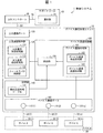
(デバイス通信管理ユニットの詳細)
図1は、制御システム1に含まれる、デバイス通信管理ユニット10およびサポートツール60の要部構成を示すブロック図である。図1に示すデバイス通信管理ユニット10は、デバイス通信制御部100と、デバイス通信ポート110と、上位通信ポート120と、上位通信制御部130と、記憶部140と、を含む構成である。なお、記載の簡潔性を担保するため、本実施の形態に直接関係のない構成は、説明およびブロック図から省略している。ただし、実施の実情に則して、デバイス通信管理ユニット10は、当該省略された構成を備えてもよい。
(Details of device communication management unit)
FIG. 1 is a block diagram showing the main configuration of the device
デバイス通信ポート110は、デバイス20とデバイス通信ケーブル30を介して通信するための伝送ケーブルが接続されるインタフェースである。上位通信ポート120は、上位コントローラ40とフィールドネットワーク50を介して通信するための伝送ケーブルが接続されるインタフェースである。
The
上位通信制御部130は、フィールドネットワーク50を介して上位コントローラ40との通信を統括して制御するものである。上位通信制御部130は、フィールドバス制御部131と、上位通信受信処理部132と、上位通信送信処理部133とを含んでいる。
The upper
フィールドバス制御部131は、フィールドネットワーク50を介したデータ伝送を管理する。上位通信受信処理部132は、上位コントローラ40からフィールドネットワーク50を介して送信される上位通信フレームを受信してデータへ復号した上で、フィールドバス制御部131へ出力する。上位通信送信処理部133は、フィールドバス制御部131から出力されるデータから上位通信フレームを再生成してフィールドネットワーク50を介して再送信(フォワード)する。フィールドバス制御部131は、上位通信受信処理部132および上位通信送信処理部133と協働して、フィールドネットワーク50を介して予め定められた制御周期毎に上位コントローラ40との間でデータを送受信する。
The
上位通信制御部130は、デバイス20(例えば、デバイス20から出力されたデータに対応するデータ)をメモリ空間およびI/O空間にどのように割り当てたかを表すIOマップを、上位コントローラ40(フィールドネットワーク50)に送信する。
The upper
デバイス通信制御部100は、デバイス20との通信に係るデバイス通信管理ユニット10の機能を統括して制御するものである。図示のデバイス通信制御部100には、機能ブロックとして、デバイス通信処理部101と、デバイス通信受信処理部102と、デバイス通信送信処理部103と、照合部104と、が含まれている。
The device
デバイス通信処理部101は、デバイス20との通信を制御し、デバイス通信受信処理部102と、デバイス通信送信処理部103と、を含んでいる。デバイス通信処理部101は、デバイス通信ポート110(1)、110(2)、・・・、110(n)の各々について、接続されているデバイス20(1)、20(2)、・・・、20(n)の各々と、第1モードで通信するか、または第2モードで通信するかを、制御する。
The device communication processing unit 101 controls communication with the
デバイス通信処理部101は、照合部104から、デバイス通信ポート110(1)、110(2)、・・・、110(n)の各々における照合結果(照合正常/照合異常)を取得する。デバイス通信処理部101は、照合部104から、或るデバイス通信ポート110について、「接続することが予定されているデバイス20(登録デバイス)と、実際に接続しているデバイス20(実デバイス)と、が一致している(照合正常)」との照合結果を取得すると、前記或るデバイス通信ポート110における通信を維持する。デバイス通信処理部101は、照合部104から、或るデバイス通信ポート110について、「接続することが予定されているデバイス20(登録デバイス)と、実際に接続しているデバイス20(実デバイス)と、が一致していない(照合異常)」との照合結果を取得すると、前記或るデバイス通信ポート110における通信を停止する。なお、或るデバイス通信ポート110について、照合部104による照合処理が実行されなかった場合、デバイス通信処理部101は、前記或るデバイス通信ポート110における通信を維持する。
The device communication processing unit 101 acquires from the
デバイス通信受信処理部102は、デバイス通信ポート110(1)、110(2)、・・・、110(n)の各々から、デバイス通信ケーブル30を介して、デバイス通信ポート110(1)、110(2)、・・・、110(n)の各々に接続されているデバイス20(1)、20(2)、・・・、20(n)が出力したデータを受信する。
The device communication
デバイス20が出力するデータは、1ビットのデータ(例えば、センサであるデバイス20が何らかの対象物を検出し(オン)、または検出していない(オフ)といったオン/オフ情報などの2値化データ)に加えて、以下のようなデータを含んでいる。すなわち、デバイス20の通信プロパティ、デバイスパラメータ、および識別データ(識別情報)等に係るアナログデータを含んでいる。デバイス通信受信処理部102は、デバイス20から、前記1ビットのデータと、前記アナログデータと、を受信する。
The data output from the
デバイス通信送信処理部103は、デバイス通信ポート110(1)、110(2)、・・・、110(n)の各々から、デバイス通信ケーブル30を介して、デバイス通信ポート110(1)、110(2)、・・・、110(n)の各々に接続されているデバイス20(1)、20(2)、・・・、20(n)へ、上位コントローラ40からの制御命令等の入力データを送信する。
The device communication
デバイス通信送信処理部103がデバイス20に送信するデータは、1ビットのデータ(例えば、アクチュエータであるデバイス20を活性化させ(オン)、または不活性化させる(オフ)指令データ)に加えて、デバイス20に対するその他の制御等に係るアナログデータを含んでいる。
In addition to 1-bit data (for example, command data that activates (turns on) or deactivates (turns off) the
照合部104は、デバイス通信ポート110(1)、110(2)、・・・、110(n)の各々について、接続することが予定されているデバイス20(登録デバイス)と、実際に接続しているデバイス20(実デバイス)と、が一致しているかを判定する照合処理を実行することができる。
The
照合部104は、例えば、記憶部140に格納されている構成設定情報テーブル141を参照して、デバイス通信ポート110(1)、110(2)、・・・、110(n)の各々について、接続することが予定されているデバイス20(登録デバイス)の識別情報を取得する。
The
照合部104は、また、デバイス通信受信処理部102から、デバイス通信ポート110(1)、110(2)、・・・、110(n)の各々に実際に接続しているデバイス20(実デバイス)の識別情報を取得する。前述の通り、デバイス通信受信処理部102は、デバイス20から、デバイス20の識別情報を含むアナログデータを受信することができる。
The
そして、照合部104は、デバイス通信ポート110(1)、110(2)、・・・、110(n)の各々について、接続することが予定されているデバイス20(登録デバイス)の識別情報と、実際に接続しているデバイス20(実デバイス)の識別情報と、が一致しているかを判定する照合処理を実行する。
The
照合部104は、デバイス通信ポート110ごとに、登録デバイスと実デバイスとの間で、「ベンダID、デバイスID、リビジョン」が一致しているかを判定し(第1照合パターン)、または、「ベンダID、デバイスID、リビジョン、シリアルNo」が一致しているかを判定する(第2照合パターン)。
The
照合部104は、デバイス通信処理部101および上位通信制御部130に、デバイス通信ポート110(1)、110(2)、・・・、110(n)の各々に係る照合処理の実行結果(照合正常/照合異常)を通知する。照合部104は、照合異常(登録デバイスの識別情報と、実デバイスの識別情報と、が一致していない)と判定した場合、上位通信制御部130に指示して、以下の情報をサポートツール60へ送信させる(通知部61へ通知させる)。すなわち、照合異常と判定した場合、照合部104は、登録デバイスの識別情報(特に、登録デバイスの形式名およびベンダ名)を、サポートツール60へ送信させる(通知部61へ通知させる)。すなわち、照合部104は、照合処理の際に用いた識別情報(ベンダID、デバイスID、リビジョン、シリアルNo)とは別の、照合処理の際に用いていない識別情報(特に、登録デバイスの形式名およびベンダ名)を、サポートツール60へ送信させる(通知部61へ通知させる)。照合部104は、デバイス通信ポート110ごとの登録デバイスの識別情報だけでなく、実デバイスの識別情報を、サポートツール60へ送信させてもよい(通知部61へ通知させてもよい)。
The
なお、照合部104は、デバイス通信ポート110(1)、110(2)、・・・、110(n)の各々について、照合処理を実行し、または照合処理を実行しない。例えば、照合部104は、デバイス通信ポート110(1)、110(3)、・・・、110(n)の各々について照合処理を実行し、デバイス通信ポート110(2)について照合処理を実行しないとすることができる。
In addition, the
また、或るデバイス通信ポート110がデバイス20との間で、オン/オフ情報といった2値化データのみを送受信している場合、つまり、第1モードでデバイス20と通信している場合、照合部104は、前記或るデバイス通信ポート110については、照合処理を実行しない。すなわち、デバイス20(S)が接続されているデバイス通信ポート110については、照合部104は照合処理を実行しない。
When a certain
記憶部140は、デバイス通信管理ユニット10が使用する各種データを格納している。すなわち、記憶部140は、デバイス通信管理ユニット10が実行する(1)制御プログラム、(2)OSプログラム、(3)各種機能を実行するためのアプリケーションプログラム、および(4)該アプリケーションプログラムを実行するときに読み出す各種データを格納している。上記の(1)〜(4)のデータは、例えば、ROM(read only memory)、フラッシュメモリ、EPROM(Erasable Programmable ROM)、EEPROM(登録商標)(Electrically EPROM)、HDD(Hard Disc Drive)等の不揮発性記憶装置に記憶される。また、記憶部140は、構成設定情報テーブル141を格納している。
The
構成設定情報テーブル141は、デバイス通信ポート110(1)、110(2)、・・・、110(n)の各々について、デバイス通信ケーブル30を介して接続することが予定されているデバイス20の識別情報を含む構成情報(コンフィギュレーションデータ)を格納している。デバイス20の識別情報とは、例えば、デバイス20の「ベンダID」、「デバイスID」、「シリアルNo」、「リビジョン(例えば、IO−Link(登録商標)リビジョン)」、「ベンダ名」、および「形式名(デバイスの名前)」である。「形式名」とは、デバイスの形式(モデル、機種)を区別する名前を意味する。
The configuration setting information table 141 includes the device communication ports 110 (1), 110 (2),..., 110 (n) of the
構成設定情報テーブル141に格納されているデバイス20の識別情報のうち、照合部104による照合処理の対象となる識別情報は、最大で、「ベンダID」、「デバイスID」、「リビジョン(例えば、IO−Linkリビジョン)」、および「シリアルNo」である。デバイス20の識別情報のうち、「ベンダ名」および「形式名(デバイスの名前)」は、照合部104による照合処理の対象となる識別情報ではない。
Among the identification information of the
(デバイス照合処理)
デバイス通信ポート110にデバイス通信ケーブル30を介してデバイス20が接続すると、照合部104は照合処理を実行する。そして、照合部104が「照合異常(デバイス通信ポート110に実際に接続しているデバイス20(実デバイス)が、そのデバイス通信ポート110に接続することが予定されているデバイス20(登録デバイス)に一致していない)」と判定すると、デバイス通信処理部101は、そのデバイス通信ポート110における通信を停止させる。
(Device verification processing)
When the
ここで、照合部104は、デバイス通信ポート110に実際に接続しているデバイス20(実デバイス)と、そのデバイス通信ポート110に接続することが予定されているデバイス20(登録デバイス)と、の「ベンダID」と、「デバイスID」と、「リビジョン」と、を照合する(第1照合パターン)。
Here, the
照合部104は、また、デバイス通信ポート110に実際に接続しているデバイス20(実デバイス)と、そのデバイス通信ポート110に接続することが予定されているデバイス20(登録デバイス)と、の「ベンダID」と、「デバイスID」と、「リビジョン」と、「シリアルNo」と、を照合してもよい(第2照合パターン)。
The
ここで、前述の通り、照合部104は、デバイス通信ポート110(1)、110(2)、・・・、110(n)の各々について、照合処理を実行する。例えば、照合部104は、デバイス通信ポート110(1)に実際に接続しているデバイス20(実デバイス)と、デバイス通信ポート110(1)に接続することが予定されているデバイス20(登録デバイス)と、の「ベンダID」と、「デバイスID」と、「リビジョン」と、を照合する。また、照合部104は、デバイス通信ポート110(2)に実際に接続しているデバイス20(実デバイス)と、デバイス通信ポート110(2)に接続することが予定されているデバイス20(登録デバイス)と、の「ベンダID」と、「デバイスID」と、「リビジョン」と、を照合する。照合部104は、デバイス通信ポート110(1)、110(3)、110(4)、・・・、110(n)について、照合処理を実行し、デバイス通信ポート110(2)については照合処理を実行しないとすることもできる。
Here, as described above, the
なお、第1照合パターンで照合処理を実行する場合、「シリアルNo」は照合の対象としないため、登録デバイスと同形式の(つまり、「ベンダID」と、「デバイスID」と、「リビジョン」とが登録デバイスと同一である)デバイス20をデバイス通信ポート110に接続させたとしても、照合部104は照合異常と判定しない。
Note that when the collation process is executed with the first collation pattern, “Serial No” is not subject to collation, and therefore has the same format as the registered device (that is, “vendor ID”, “device ID”, and “revision”). Even if the
(サポートツールの詳細)
サポートツール60は通知部61を備えている。通知部61は、デバイス通信管理ユニット10において実行された照合処理(デバイス通信ポート110ごとの、登録デバイスと実デバイスとの照合処理)の結果をユーザに通知することができる。ここで、前記照合処理の結果、「照合異常(登録デバイスの識別情報と実デバイスの識別情報とが一致しない)」と判定された場合、通知部61は、登録デバイスの識別情報(特に、登録デバイスのベンダ名および形式名等)をユーザに通知する。通知部61は、照合異常と判定された場合、さらに、「ベンダ名」および「形式名」に加えて、登録デバイスの「シリアルNo」、「リビジョン(例えば、IO−Linkリビジョン)」をユーザに通知してもよい。これらを通知されることにより、ユーザは、正しいデバイス(登録デバイス)が何かを容易に把握することができる。
(Details of support tools)
The
例えば、デバイス通信管理ユニット10は照合処理(デバイス通信ポート110ごとの、登録デバイスと実デバイスとの照合処理)を実行し、その照合処理の結果を、フィールドネットワーク50(および、上位コントローラ40)を介して、サポートツール60に送信する。デバイス通信管理ユニット10は、照合異常(登録デバイスの識別情報と実デバイスの識別情報とが一致しない)と判定すると、登録デバイスの識別情報を、フィールドネットワーク50(および、上位コントローラ40)を介して、サポートツール60に送信する。
For example, the device
そして、サポートツール60は、フィールドネットワーク50(および、上位コントローラ40)を介して、デバイス通信管理ユニット10から前記照合処理の結果を受信する。サポートツール60は、また、フィールドネットワーク50(および、上位コントローラ40)を介して、デバイス通信管理ユニット10から、登録デバイスの「ベンダ名、形式名、シリアルNo、リビジョン」等を含む識別情報を受信する。
The
通知部61は、デバイス通信管理ユニット10からサポートツール60が受信した「前記照合処理の結果、および、登録デバイスの識別情報(特に、登録デバイスの「ベンダ名、形式名、シリアルNo、リビジョン」等)」をユーザに通知する。すなわち、通知部61は、照合部104が前記照合処理に際しては照合の対象としなかった識別情報である「形式名およびベンダ名」を、登録デバイスの識別情報の1つとしてユーザに通知する。通知部61は、デバイス通信ポート110ごとの登録デバイスの形式名のみをユーザに通知してもより。ここで、前述の通り、照合部104は、「ベンダID、デバイスID、リビジョン(および、シリアルNo)」を照合処理の際に、登録デバイスと実デバイスとの間で比較する識別情報として用いる。
The
なお、通知部61を備えるサポートツール60(または、通知部61を備えるHMI80)は、デバイス通信管理ユニット10から、デバイス通信ポート110ごとの登録デバイスの識別情報だけでなく、実デバイスの識別情報を受信してもよい。サポートツール60(または、HMI80)は、デバイス通信管理ユニット10から受信した「デバイス通信ポート110ごとの登録デバイスの識別情報」と併せて、「デバイス通信ポート110ごとの実デバイスの識別情報」をユーザに通知してもよい。
The
(識別情報の登録方法)
図3は、制御システム1において、デバイス通信管理ユニット10について、「デバイス通信ポート110(1)、110(2)、・・・、110(n)の各々に接続させる予定のデバイス20(1)、20(2)、・・・、20(n)の各々の識別情報」(構成情報)を登録する方法を説明する図である。
(Identification information registration method)
FIG. 3 shows that the device
デバイス通信管理ユニット10は、或るデバイス通信ポート110に実際に接続させるデバイス20が、意図通りのデバイス20(前記或るデバイス通信ポート110に接続することが予定されているデバイス20)であることを確認する照合処理を実行する。
In the device
デバイス通信管理ユニット10に前記照合処理を実行させるため、ユーザは、サポートツール60を用いて、デバイス通信管理ユニット10の前記或るデバイス通信ポート110に接続させる予定のデバイス20の識別情報を予め登録しておく。
In order to cause the device
すなわち、先ず、ユーザは、サポートツール60に、「デバイス通信ポート110(1)、110(2)、・・・、110(n)の各々に接続させる予定のデバイス20(1)、20(2)、・・・、20(n)の各々の識別情報」を入力する。そして、サポートツール60は、デバイス通信ポート110ごとにユーザが手入力したデバイス20の識別情報を、デバイス通信管理ユニット10に送信する。デバイス通信管理ユニット10は、サポートツール60からの「デバイス通信ポート110ごとにユーザが手入力したデバイス20の識別情報」を構成設定情報テーブル141に格納する。
That is, first, the user makes the
ユーザは、サポートツール60(または、HMI80)において登録デバイスの識別情報を設定する際、登録デバイスの「ベンダ名」および「形式名(デバイス名)」に係る情報を、登録デバイスの「ベンダID、デバイスID、リビジョン(および、シリアルNo)」に加えて設定する。 When setting the identification information of a registered device in the support tool 60 (or HMI 80), the user uses information related to the “vendor name” and “format name (device name)” of the registered device as the “vendor ID, Set in addition to “Device ID, Revision (and Serial No.)”.
以上に説明してきたように、制御システム1において、前記構成情報(構成設定情報テーブル141に格納されている情報)に含まれる識別情報は、ユーザにより予め登録された情報である。
As described above, in the
前記の構成によれば、制御システム1は、ユーザが予め登録した前記構成情報を用いて、デバイス通信ポート110に接続することが予定されているデバイス20(登録デバイス)の形式名を、ユーザに通知することができるという効果を奏する。
According to the above configuration, the
(従来のデバイス通信管理ユニットにおける照合結果の通知方法)
従来のデバイス通信管理ユニット9は、デバイス通信ポート110に接続される予定のデバイス20の識別情報(「ベンダID」、「デバイスID」、「シリアルNo」、および「リビジョン(例えば、IO−Linkリビジョン)」の少なくとも1つ)を数値として表示させることはできた。
(Notification method of verification result in the conventional device communication management unit)
The conventional device communication management unit 9 includes identification information (“vendor ID”, “device ID”, “serial No”, and “revision (for example, IO-Link revision) of the
しかしながら、従来のデバイス通信管理ユニット9が表示する「デバイス通信ポート110に接続される予定のデバイス20の識別情報」は、数値(「ベンダID」、「デバイスID」、「シリアルNo」、および「リビジョン(例えば、IO−Linkリビジョン)」の少なくとも1つを示す数値)であったため、ユーザにとって、「デバイス通信ポート110に接続される予定のデバイス20」が実際にどのデバイスであるのかを把握するのが困難であった。すなわち、ユーザは、数値として表示された情報のみから、「デバイス通信ポート110に接続される予定のデバイス20」を特定しなければならず、例えば、どの形式のデバイス20をどの形式のデバイス20と誤って、デバイス通信ポート110に接続したか分かりにくかった。ユーザは、数値として表示された情報(番号)からデバイス20の形式を検索し特定していた。
However, the “identification information of the
(本発明の一実施形態に係るデバイス通信管理ユニットにおける照合結果の通知方法)
サポートツール60(または、HMI80)の備える通知部61は、登録デバイス(デバイス通信ポート110に接続される予定のデバイス20)の識別情報と実デバイス(デバイス通信ポート110に実際に接続されているデバイス20)の識別情報と、を「形式名(デバイス名)」で表示する。サポートツール60(または、HMI80)の備える通知部61は、デバイス通信管理ユニット10は、登録デバイスおよび実デバイスの「ベンダ名、形式名(デバイス名)、リビジョン、および、シリアルNo」等の識別情報をユーザに通知することができる。したがって、ユーザは、これらの識別情報を用いて、「正しいデバイス(デバイス通信ポート110に接続される予定のデバイス20)がどのデバイスであるのか」を容易に把握することができる。
(Notification method of verification result in device communication management unit according to one embodiment of the present invention)
The
これまで、「照合異常と判定した場合に照合部104が、登録デバイスの識別情報(特に、登録デバイスの形式名)を、サポートツール60へ送信させる(通知部61へ通知させる)」例を中心に説明を行ってきた。しかしながら、照合部104が照合異常と判定した場合に、照合部104が、登録デバイスの識別情報をサポートツール60へ送信させることは必須ではない。すなわち、デバイス通信管理ユニット10が、主体的に、通知部61を備えるサポートツール60(または、HMI80)に、登録デバイス(および実デバイス)の識別情報を送信してもよいし、サポートツール60(または、HMI80)がデバイス通信管理ユニット10に、登録デバイス(および実デバイス)の識別情報の送信を要求してもよい。
Up to now, an example of “when the
例えば、照合異常との判定結果を受信したサポートツール60(通知部61)が、上位コントローラ40(フィールドネットワーク50)を介して、デバイス通信管理ユニット10から、構成設定情報テーブル141に格納されている構成情報(特に、デバイス通信ポート110ごとの登録デバイスの識別情報)を取得してもよい。すなわち、通知部61を備えるサポートツール60(HMI80)が、上位コントローラ40(フィールドネットワーク50)を介して、デバイス通信管理ユニット10に、デバイス通信ポート110ごとの登録デバイスの識別情報(特に、形式名等)の送信を要求するメッセージを出力してもよい。前記メッセージを受信したデバイス通信管理ユニット10は、構成設定情報テーブル141を参照して取得した「デバイス通信ポート110ごとの登録デバイスの識別情報(特に、形式名等)」を、サポートツール60(HMI80)に送信する。
For example, the support tool 60 (notification unit 61) that has received the determination result of the collation abnormality is stored in the configuration setting information table 141 from the device
なお、通知部61を備えるサポートツール60(または、通知部61を備えるHMI80)は、デバイス通信管理ユニット10から、デバイス通信ポート110ごとの登録デバイスの識別情報だけでなく、実デバイスの識別情報を受信してもよい。サポートツール60(または、HMI80)は、デバイス通信管理ユニット10から受信した「デバイス通信ポート110ごとの登録デバイスの識別情報」と併せて、「デバイス通信ポート110ごとの実デバイスの識別情報」をユーザに通知してもよい。
The
ここで、デバイス20(特に、デバイス20(C))は、自機の「ベンダ名」および「形式名(デバイス名)」などの識別情報を保持している。通知部61を備えるサポートツール60(または、通知部61を備えるHMI80)は、デバイス通信管理ユニット10に、実デバイスの「ベンダ名」および「形式名(デバイス名)」などの識別情報の送信を要求するメッセージを出力してもよい。前記メッセージを受信したデバイス通信管理ユニット10は、デバイス通信ポート110に接続されているデバイス20(特に、デバイス20(C))と第2モードで通信を行うことにより、デバイス20(実デバイス)の識別情報を、デバイス通信ポート110ごとに取得する。デバイス通信管理ユニット10は、デバイス通信ポート110ごとの実デバイスの識別情報(ベンダ名および形式名(デバイス名)を含む)を、サポートツール60(または、HMI80)に送信する。サポートツール60(または、HMI80)の備える通知部61は、デバイス通信管理ユニット10から取得した「デバイス通信ポート110ごとの実デバイスの識別情報(特に、ベンダ名および形式名)」を、「デバイス通信ポート110ごとの登録デバイスの識別情報(特に、ベンダ名および形式名)」と併せて、ユーザに通知する。したがって、ユーザは、デバイス通信ポート110ごとに、「正しいデバイス(登録デバイス)が何か」、および、「誤って接続させてしまったデバイスが何か」を簡単に容易に把握することができる。
Here, the device 20 (particularly, the device 20 (C)) holds identification information such as “vendor name” and “format name (device name)” of its own device. The
(表示処理および照合処理の実行装置等に係るバリエーション)
これまでに、制御システム1について、「デバイス通信管理ユニット10が、デバイス通信ポート110ごとに、接続の予定されているデバイス20(登録デバイス)の識別情報と、実際に接続されたデバイス20(実デバイス)の識別情報とを照合する照合部104を備え、サポートツール60が、デバイス通信ポート110に接続の予定されているデバイス(登録デバイス)の形式名を、照合部104によって照合異常と判定された場合にユーザに通知する通知部61を備える」例について説明を行ってきた。
(Variations related to display processing and collation processing execution devices)
So far, regarding the
しかしながら、制御システム1において、「照合処理(登録情報と実接続情報との一致判断、つまり、登録デバイスの識別情報と実デバイスの識別情報との一致判断)を実行する照合部104を備えるのがデバイス通信管理ユニット10であること」、および、「表示処理(登録デバイスの形式名の通知)を実行する通知部61を備えるのがサポートツール60であること」は、必須ではない。表示処理および照合処理の各々を実行する装置について、可能な組み合わせの例を、図4から図10を用いて、以下に説明していく。
However, the
すなわち、制御システム1において、照合部104は、上位コントローラ40、デバイス通信管理ユニット10、上位コントローラ40に接続しているサポートツール60またはHMI80(外部装置)、および、デバイス通信管理ユニット10に接続しているサポートツール60またはHMI80(外部装置)の少なくとも1つに備えられている。
That is, in the
前記の構成によれば、照合部104は、上位コントローラ40、デバイス通信管理ユニット10、上位コントローラ40に接続しているサポートツール60またはHMI80(外部装置)、および、デバイス通信管理ユニット10に接続しているサポートツール60またはHMI80(外部装置)の少なくとも1つに備えられる。したがって、制御システム1は、上位コントローラ40、デバイス通信管理ユニット10、上位コントローラ40に接続しているサポートツール60またはHMI80(外部装置)、および、デバイス通信管理ユニット10に接続しているサポートツール60またはHMI80(外部装置)の少なくとも1つにおいて、デバイス通信受信処理部102により取得可能な識別情報(実デバイスの識別情報)と、前記構成情報に含まれる識別情報(登録デバイスの識別情報)とを照合し、照合結果(特に、登録デバイスの形式名)を表示することができるという効果を奏する。
According to the above configuration, the
また、制御システム1において、通知部61は、デバイス通信ポート110に接続することが予定されているデバイス20(登録デバイス)の形式名を、上位コントローラ40、デバイス通信管理ユニット10、上位コントローラ40に接続しているサポートツール60またはHMI80(外部装置)、および、デバイス通信管理ユニット10に接続しているサポートツール60またはHMI80(外部装置)の少なくとも1つに表示させる。
Further, in the
前記の構成によれば、制御システム1は、デバイス通信ポート110に接続することが予定されているデバイス20(登録デバイス)の形式名を、上位コントローラ40、デバイス通信管理ユニット10、上位コントローラ40に接続しているサポートツール60またはHMI80(外部装置)、および、デバイス通信管理ユニット10に接続しているサポートツール60またはHMI80(外部装置)の少なくとも1つに表示させることにより、ユーザに通知することができるという効果を奏する。
According to the above configuration, the
図4は、制御システム1における表示処理および照合処理の実行主体の例を示す表である。すなわち、図4には、制御システム1における、表示処理、照合処理(登録情報と実接続情報との一致判断)、登録情報の取得、実接続情報の取得の各処理について、実行主体等の例が表形式で示されている。
FIG. 4 is a table showing an example of the execution subject of the display process and the collation process in the
図4に示す表の1行目は、表示処理はHMI80が実行し、照合(登録情報と実接続情報との一致判断)処理はHMI80が実行する構成を示している。1行目の構成において、デバイス通信管理ユニット10のデバイス通信ポート110ごとの登録デバイス(接続予定デバイス)の識別情報の取得については、HMI80がデバイス通信管理ユニット10に対して問合せを行う。デバイス通信管理ユニット10は、構成設定情報テーブル141に格納されている構成情報(デバイス通信ポート110ごとの、登録デバイスの識別情報)を、HMI80に通知する。また、デバイス通信管理ユニット10のデバイス通信ポート110ごとの実デバイス(デバイス通信ポート110の各々に実際に接続しているデバイス20)の識別情報の取得については、HMI80がデバイス20に対して問合せを行う。すなわち、HMI80は、デバイス通信管理ユニット10に、デバイス20から、デバイス20の識別情報を取得させることにより、デバイス通信ポート110ごとの実デバイスの識別情報を取得する。
The first row of the table shown in FIG. 4 shows a configuration in which the display process is executed by the
図4に示す表の2行目は、表示処理はHMI80が実行し、照合(登録情報と実接続情報との一致判断)処理はHMI80が実行する構成を示している。2行目の構成において、デバイス通信ポート110ごとの登録デバイス(接続予定デバイス)の識別情報の取得については、HMI80がデバイス通信管理ユニット10に対して問合せを行う。デバイス通信管理ユニット10は、構成設定情報テーブル141に格納されている構成情報(デバイス通信ポート110ごとの、登録デバイスの識別情報)を、HMI80に通知する。また、デバイス通信ポート110ごとの実デバイス(実際にそのポートに接続しているデバイス20)の識別情報の取得については、HMI80がデバイス通信管理ユニット10に対して問合せを行う。デバイス通信管理ユニット10は、デバイス通信ポート110に実際に接続しているデバイス20から取得した「デバイス通信ポート110ごとの実デバイスの識別情報142」を、HMI80に通知する。
The second row of the table shown in FIG. 4 shows a configuration in which the display process is performed by the
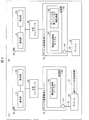
図5は、制御システム1における表示処理および照合処理の実行主体の例を示す図である。図5の(A)は、「HMI80が、表示処理を担う通知部61と、照合処理を担う照合部104と、を備える」例を示している。図5の(A)におけるHMI80は、「デバイス通信ポート110ごとの登録デバイス」の識別情報をデバイス通信管理ユニット10の構成設定情報テーブル141から取得し、「デバイス通信ポート110ごとの実デバイスの識別情報21」をデバイス20から取得する。図5の(A)に示されている構成は、図4に示す表の1行目に示されている構成に対応する。図5の(B)は、「HMI80が、表示処理を担う通知部61と、照合処理を担う照合部104と、を備える」例を示している。図5の(B)におけるHMI80は、「デバイス通信ポート110ごとの登録デバイス」および「デバイス通信ポート110ごとの実デバイスの識別情報」を、デバイス通信管理ユニット10の構成設定情報テーブル141および「デバイス通信ポート110ごとの実デバイスの識別情報142」から取得する。図5の(B)に示されている構成は、図4に示す表の2行目に示されている構成に対応する。
FIG. 5 is a diagram illustrating an example of an execution subject of display processing and collation processing in the
図4に示す表の3行目は、表示処理はHMI80が実行し、照合(登録情報と実接続情報との一致判断)処理は上位コントローラ40が実行する構成を示している。3行目の構成において、デバイス通信ポート110ごとの登録デバイス(接続予定デバイス)の識別情報の取得については、上位コントローラ40がデバイス通信管理ユニット10に対して問合せを行う。デバイス通信管理ユニット10は、構成設定情報テーブル141に格納されている構成情報(デバイス通信ポート110ごとの、登録デバイスの識別情報)を、上位コントローラ40に通知する。また、デバイス通信ポート110ごとの実デバイス(実際にそのポートに接続しているデバイス20)の識別情報の取得については、上位コントローラ40がデバイス20に対して問合せを行う。すなわち、上位コントローラ40は、デバイス通信管理ユニット10に、デバイス20から、デバイス20の識別情報を取得させることにより、デバイス通信ポート110ごとの実デバイスの識別情報を取得する。HMI80は、上位コントローラ40が実行した照合処理の結果をユーザに通知する。
The third row of the table shown in FIG. 4 shows a configuration in which the display process is executed by the
図4に示す表の4行目は、表示処理はHMI80が実行し、照合(登録情報と実接続情報との一致判断)処理は上位コントローラ40が実行する構成を示している。4行目の構成において、デバイス通信ポート110ごとの登録デバイス(接続予定デバイス)の識別情報の取得については、上位コントローラ40がデバイス通信管理ユニット10に対して問合せを行う。デバイス通信管理ユニット10は、構成設定情報テーブル141に格納されている構成情報(デバイス通信ポート110ごとの、登録デバイスの識別情報)を、上位コントローラ40に通知する。また、デバイス通信ポート110ごとの実デバイス(実際にそのポートに接続しているデバイス20)の識別情報の取得については、上位コントローラ40がデバイス通信管理ユニット10に対して問合せを行う。デバイス通信管理ユニット10は、デバイス通信ポート110に実際に接続しているデバイス20から取得した「デバイス通信ポート110ごとの実デバイスの識別情報142」を、上位コントローラ40に通知する。HMI80は、上位コントローラ40が実行した照合処理の結果をユーザに通知する。
The fourth row of the table shown in FIG. 4 shows a configuration in which the display process is executed by the
図6は、制御システム1における表示処理および照合処理の実行主体についての、図5に示めした例とは別の例を示す図である。
図6の(A)は、「表示処理を担う通知部61をHMI80が備え、照合処理を担う照合部104を上位コントローラ40が備える」例を示している。図6の(A)における上位コントローラ40は、「デバイス通信ポート110ごとの登録デバイス」の識別情報をデバイス通信管理ユニット10の構成設定情報テーブル141から取得し、「デバイス通信ポート110ごとの実デバイスの識別情報21」をデバイス20から取得する。図6の(A)に示されている構成は、図4に示す表の3行目に示されている構成に対応する。図6の(B)は、「表示処理を担う通知部61をHMI80が備え、照合処理を担う照合部104を上位コントローラ40が備える」例を示している。図6の(B)における上位コントローラ40は、「デバイス通信ポート110ごとの登録デバイス」および「デバイス通信ポート110ごとの実デバイスの識別情報」を、デバイス通信管理ユニット10の構成設定情報テーブル141および「デバイス通信ポート110ごとの実デバイスの識別情報142」から取得する。図6の(B)に示されている構成は、図4に示す表の4行目に示されている構成に対応する。
FIG. 6 is a diagram showing an example different from the example shown in FIG. 5 about the execution subject of the display process and the collation process in the
FIG. 6A illustrates an example of “the
図4に示す表の5行目は、表示処理はHMI80が実行し、照合(登録情報と実接続情報との一致判断)処理はデバイス通信管理ユニット10が実行する構成を示している。5行目の構成において、デバイス通信ポート110ごとの登録デバイス(接続予定デバイス)の識別情報の取得については、デバイス通信管理ユニット10自身が保有している「登録デバイスの識別情報」を利用する。すなわち、デバイス通信管理ユニット10は、構成設定情報テーブル141を参照して、「デバイス通信ポート110ごとの、登録デバイスの識別情報」を取得する。また、デバイス通信ポート110ごとの実デバイス(実際にそのポートに接続しているデバイス20)の識別情報の取得については、デバイス通信管理ユニット10がデバイス20に対して問合せを行う。すなわち、デバイス通信管理ユニット10は、デバイス通信ポート110に実際に接続しているデバイス20から、デバイス20の識別情報を取得する。HMI80は、デバイス通信管理ユニット10が実行した照合処理の結果をユーザに通知する。
The fifth line of the table shown in FIG. 4 shows a configuration in which the display process is executed by the
図4に示す表の6行目は、表示処理はHMI80が実行し、照合(登録情報と実接続情報との一致判断)処理はデバイス通信管理ユニット10が実行する構成を示している。6行目の構成において、デバイス通信ポート110ごとの登録デバイス(接続予定デバイス)の識別情報の取得については、デバイス通信管理ユニット10自身が保有している「登録デバイスの識別情報」を利用する。すなわち、デバイス通信管理ユニット10は、構成設定情報テーブル141を参照して、「デバイス通信ポート110ごとの、登録デバイスの識別情報」を取得する。また、デバイス通信ポート110ごとの実デバイス(実際にそのポートに接続しているデバイス20)の識別情報の取得については、デバイス通信管理ユニット10自身が保有している「実デバイスの識別情報」を利用する。すなわち、デバイス通信管理ユニット10は、デバイス通信ポート110に実際に接続しているデバイス20から取得した「デバイス通信ポート110ごとの実デバイスの識別情報142」を参照して、「実デバイスの識別情報」を取得する。HMI80は、デバイス通信管理ユニット10が実行した照合処理の結果をユーザに通知する。
The sixth line of the table shown in FIG. 4 shows a configuration in which the display process is executed by the
図7は、制御システム1における表示処理および照合処理の実行主体についての、図5および図6に示した例とは別の例を示す図である。図7の(A)は、「表示処理を担う通知部61をHMI80が備え、照合処理を担う照合部104をデバイス通信管理ユニット10が備える」例を示している。図7の(A)におけるデバイス通信管理ユニット10は、「デバイス通信ポート110ごとの登録デバイス」の識別情報を、構成設定情報テーブル141を参照して取得し、「デバイス通信ポート110ごとの実デバイスの識別情報21」をデバイス20から取得する。図7の(A)に示されている構成は、図4に示す表の5行目に示されている構成に対応する。図7の(B)は、「表示処理を担う通知部61をHMI80が備え、照合処理を担う照合部104をデバイス通信管理ユニット10が備える」例を示している。図7の(B)におけるデバイス通信管理ユニット10は、「デバイス通信ポート110ごとの登録デバイス」および「デバイス通信ポート110ごとの実デバイスの識別情報」を、構成設定情報テーブル141および「デバイス通信ポート110ごとの実デバイスの識別情報142」を参照して、取得する。図7の(B)に示されている構成は、図4に示す表の6行目に示されている構成に対応する。
FIG. 7 is a diagram illustrating an example different from the example illustrated in FIGS. 5 and 6 regarding the execution subject of the display process and the collation process in the
図4に示す表の7行目は、表示処理はサポートツール60が実行し、照合(登録情報と実接続情報との一致判断)処理はサポートツール60が実行する構成を示している。7行目の構成において、デバイス通信ポート110ごとの登録デバイス(接続予定デバイス)の識別情報の取得については、サポートツール60がデバイス通信管理ユニット10に対して問合せを行う。デバイス通信管理ユニット10は、構成設定情報テーブル141に格納されている構成情報(デバイス通信ポート110ごとの、登録デバイスの識別情報)を、サポートツール60に通知する。また、デバイス通信ポート110ごとの実デバイス(実際にそのポートに接続しているデバイス20)の識別情報の取得については、サポートツール60がデバイス20に対して問合せを行う。すなわち、サポートツール60は、デバイス通信管理ユニット10に、デバイス20から、デバイス20の識別情報を取得させることにより、デバイス通信ポート110ごとの実デバイスの識別情報を取得する。
The seventh line of the table shown in FIG. 4 shows a configuration in which the
図4に示す表の8行目は、表示処理はサポートツール60が実行し、照合(登録情報と実接続情報との一致判断)処理はサポートツール60が実行する構成を示している。8行目の構成において、デバイス通信ポート110ごとの登録デバイス(接続予定デバイス)の識別情報の取得については、サポートツール60がデバイス通信管理ユニット10に対して問合せを行う。デバイス通信管理ユニット10は、構成設定情報テーブル141に格納されている構成情報(デバイス通信ポート110ごとの、登録デバイスの識別情報)を、サポートツール60に通知する。また、デバイス通信ポート110ごとの実デバイス(実際にそのポートに接続しているデバイス20)の識別情報の取得については、サポートツール60がデバイス通信管理ユニット10に対して問合せを行う。デバイス通信管理ユニット10は、デバイス通信ポート110に実際に接続しているデバイス20から取得した「デバイス通信ポート110ごとの実デバイスの識別情報142」を、サポートツール60に通知する。
The eighth line of the table shown in FIG. 4 shows a configuration in which the
図8は、制御システム1における表示処理および照合処理の実行主体についての、図5〜図7までに示した例とは別の例を示す図である。図8の(A)は、「サポートツール60が、表示処理を担う通知部61と、照合処理を担う照合部104と、を備える」例を示している。図8の(A)におけるサポートツール60は、「デバイス通信ポート110ごとの登録デバイス」の識別情報をデバイス通信管理ユニット10の構成設定情報テーブル141から取得し、「デバイス通信ポート110ごとの実デバイスの識別情報21」をデバイス20から取得する。図8の(A)に示されている構成は、図4に示す表の7行目に示されている構成に対応する。図8の(B)は、「サポートツール60が、表示処理を担う通知部61と、照合処理を担う照合部104と、を備える」例を示している。図8の(B)におけるサポートツール60は、「デバイス通信ポート110ごとの登録デバイス」および「デバイス通信ポート110ごとの実デバイスの識別情報」を、デバイス通信管理ユニット10の構成設定情報テーブル141および「デバイス通信ポート110ごとの実デバイスの識別情報142」から取得する。図8の(B)に示されている構成は、図4に示す表の8行目に示されている構成に対応する。
FIG. 8 is a diagram illustrating an example different from the examples illustrated in FIGS. 5 to 7 regarding the execution subject of the display process and the collation process in the
図4に示す表の9行目は、表示処理はサポートツール60が実行し、照合(登録情報と実接続情報との一致判断)処理は上位コントローラ40が実行する構成を示している。9行目の構成において、デバイス通信ポート110ごとの登録デバイス(接続予定デバイス)の識別情報の取得については、上位コントローラ40がデバイス通信管理ユニット10に対して問合せを行う。デバイス通信管理ユニット10は、構成設定情報テーブル141に格納されている構成情報(デバイス通信ポート110ごとの、登録デバイスの識別情報)を、上位コントローラ40に通知する。また、デバイス通信ポート110ごとの実デバイス(実際にそのポートに接続しているデバイス20)の識別情報の取得については、上位コントローラ40がデバイス20に対して問合せを行う。すなわち、上位コントローラ40は、デバイス通信管理ユニット10に、デバイス20から、デバイス20の識別情報を取得させることにより、デバイス通信ポート110ごとの実デバイスの識別情報を取得する。サポートツール60は、上位コントローラ40が実行した照合処理の結果をユーザに通知する。
The ninth line of the table shown in FIG. 4 shows a configuration in which the display process is executed by the
図4に示す表の10行目は、表示処理はサポートツール60が実行し、照合(登録情報と実接続情報との一致判断)処理は上位コントローラ40が実行する構成を示している。10行目の構成において、デバイス通信ポート110ごとの登録デバイス(接続予定デバイス)の識別情報の取得については、上位コントローラ40がデバイス通信管理ユニット10に対して問合せを行う。デバイス通信管理ユニット10は、構成設定情報テーブル141に格納されている構成情報(デバイス通信ポート110ごとの、登録デバイスの識別情報)を、上位コントローラ40に通知する。また、デバイス通信ポート110ごとの実デバイス(実際にそのポートに接続しているデバイス20)の識別情報の取得については、上位コントローラ40がデバイス通信管理ユニット10に対して問合せを行う。デバイス通信管理ユニット10は、デバイス通信ポート110に実際に接続しているデバイス20から取得した「デバイス通信ポート110ごとの実デバイスの識別情報142」を、上位コントローラ40に通知する。サポートツール60は、上位コントローラ40が実行した照合処理の結果をユーザに通知する。
The 10th line of the table shown in FIG. 4 shows a configuration in which the display process is executed by the
図9は、制御システム1における表示処理および照合処理の実行主体についての、図5〜図8までに示した例とは別の例を示す図である。図9の(A)は、「表示処理を担う通知部61をサポートツール60が備え、照合処理を担う照合部104を上位コントローラ40が備える」例を示している。図9の(A)における上位コントローラ40は、「デバイス通信ポート110ごとの登録デバイス」の識別情報をデバイス通信管理ユニット10の構成設定情報テーブル141から取得し、「デバイス通信ポート110ごとの実デバイスの識別情報21」をデバイス20から取得する。図9の(A)に示されている構成は、図4に示す表の9行目に示されている構成に対応する。図9の(B)は、「表示処理を担う通知部61をサポートツール60が備え、照合処理を担う照合部104を上位コントローラ40が備える」例を示している。図9の(B)における上位コントローラ40は、「デバイス通信ポート110ごとの登録デバイス」および「デバイス通信ポート110ごとの実デバイスの識別情報」を、デバイス通信管理ユニット10の構成設定情報テーブル141および「デバイス通信ポート110ごとの実デバイスの識別情報142」から取得する。図9の(B)に示されている構成は、図4に示す表の10行目に示されている構成に対応する。
FIG. 9 is a diagram showing an example different from the examples shown in FIGS. 5 to 8 regarding the execution subject of the display process and the collation process in the
図4に示す表の11行目は、表示処理はサポートツール60が実行し、照合(登録情報と実接続情報との一致判断)処理はデバイス通信管理ユニット10が実行する構成を示している。11行目の構成において、デバイス通信ポート110ごとの登録デバイス(接続予定デバイス)の識別情報の取得については、デバイス通信管理ユニット10自身が保有している「登録デバイスの識別情報」を利用する。すなわち、デバイス通信管理ユニット10は、構成設定情報テーブル141を参照して、「デバイス通信ポート110ごとの、登録デバイスの識別情報」を取得する。また、デバイス通信ポート110ごとの実デバイス(実際にそのポートに接続しているデバイス20)の識別情報の取得については、デバイス通信管理ユニット10がデバイス20に対して問合せを行う。すなわち、デバイス通信管理ユニット10は、デバイス通信ポート110に実際に接続しているデバイス20から、デバイス20の識別情報を取得する。サポートツール60は、デバイス通信管理ユニット10が実行した照合処理の結果をユーザに通知する。
The eleventh line of the table shown in FIG. 4 shows a configuration in which the display process is executed by the
図4に示す表の12行目は、表示処理はサポートツール60が実行し、照合(登録情報と実接続情報との一致判断)処理はデバイス通信管理ユニット10が実行する構成を示している。12行目の構成において、デバイス通信ポート110ごとの登録デバイス(接続予定デバイス)の識別情報の取得については、デバイス通信管理ユニット10自身が保有している「登録デバイスの識別情報」を利用する。すなわち、デバイス通信管理ユニット10は、構成設定情報テーブル141を参照して、「デバイス通信ポート110ごとの、登録デバイスの識別情報」を取得する。また、デバイス通信ポート110ごとの実デバイス(実際にそのポートに接続しているデバイス20)の識別情報の取得については、デバイス通信管理ユニット10自身が保有している「実デバイスの識別情報」を利用する。すなわち、デバイス通信管理ユニット10は、デバイス通信ポート110に実際に接続しているデバイス20から取得した「デバイス通信ポート110ごとの実デバイスの識別情報142」を参照して、「実デバイスの識別情報」を取得する。サポートツール60は、デバイス通信管理ユニット10が実行した照合処理の結果をユーザに通知する。
The twelfth line of the table shown in FIG. 4 shows a configuration in which the display process is executed by the
図10は、制御システム1における表示処理および照合処理の実行主体についての、図5〜図9までに示した例とは別の例を示す図である。図10の(A)は、「表示処理を担う通知部61をサポートツール60が備え、照合処理を担う照合部104をデバイス通信管理ユニット10が備える」例を示している。図10の(A)におけるデバイス通信管理ユニット10は、「デバイス通信ポート110ごとの登録デバイス」の識別情報を、構成設定情報テーブル141を参照して取得し、「デバイス通信ポート110ごとの実デバイスの識別情報21」をデバイス20から取得する。図10の(A)に示されている構成は、図4に示す表の11行目に示されている構成に対応する。図10の(B)は、「表示処理を担う通知部61をサポートツール60が備え、照合処理を担う照合部104をデバイス通信管理ユニット10が備える」例を示している。図10の(B)におけるデバイス通信管理ユニット10は、「デバイス通信ポート110ごとの登録デバイス」および「デバイス通信ポート110ごとの実デバイスの識別情報」を、構成設定情報テーブル141および「デバイス通信ポート110ごとの実デバイスの識別情報142」を参照して、取得する。図10の(B)に示されている構成は、図4に示す表の12行目に示されている構成に対応する。
FIG. 10 is a diagram illustrating an example different from the examples illustrated in FIGS. 5 to 9 regarding the execution subject of the display process and the collation process in the
制御システム1における表示処理および照合処理の実行主体について、照合部104は、デバイス通信管理ユニット10(スレーブ装置)に備えられ、通知部61は、デバイス通信ポート110に接続することが予定されているデバイス20(登録デバイス)の形式名を、上位コントローラ40に接続している外部装置(サポートツール60またはHMI80)に表示させるのが最も好ましい。
Regarding the execution subject of display processing and verification processing in the
前記の構成によれば、デバイス通信管理ユニット10が記憶部140(特に、構成設定情報テーブル141)およびデバイス通信受信処理部102(取得部)を備えている場合、デバイス通信管理ユニット10は、前記照合を実行するための情報を他の装置から取得する必要がない。つまり、制御システム1において、デバイス通信管理ユニット10が記憶部140およびデバイス通信受信処理部102を備えている場合、デバイス通信管理ユニット10は、他の装置から別途、デバイス通信ポート110に接続することが予定されているデバイス20(登録デバイス)の識別情報、および、デバイス通信ポート110に接続されたデバイス20(実デバイス)の識別情報を取得することなく、前記照合を実行することができる。制御システム1において、「デバイス通信管理ユニット10が、他の装置から別途、デバイス通信ポート110に接続することが予定されているデバイス20(登録デバイス)の識別情報、および、デバイス通信ポート110に接続されたデバイス20(実デバイス)の識別情報を取得する」ためのプログラム等を用意せずとも、デバイス通信管理ユニット10は前記照合を実行する。
According to the above configuration, when the device
したがって、制御システム1において、前記プログラム等の作成・調整のためのユーザ作業が不要になり、ユーザの負担を低減することができるという効果を奏する。また、デバイス通信管理ユニット10と他の装置との間の情報の遣り取りが不要となるため、制御システム1の立ち上がり時間を短縮することができるという効果を奏する。
Therefore, in the
また、HMI80に、デバイス通信ポート110に接続することが予定されているデバイス20(登録デバイス)の形式名を表示させることにより、ユーザにとって見易い表示とすることができるという効果を奏する。
In addition, by displaying the format name of the device 20 (registered device) that is scheduled to be connected to the
なお、上位コントローラ40(コントローラ)が照合処理を実行する場合(つまり、上位コントローラ40が照合部104を備える場合)、制御システム1においてデバイス通信管理ユニット10を保守・交換する際のシステムダウンタイムを短縮することができるという効果を奏する。すなわち、交換後のデバイス通信管理ユニット10に対して、デバイス通信ポート110に接続することが予定されているデバイス20(登録デバイス)の識別情報を再設定する必要がないという効果を奏する。
When the host controller 40 (controller) executes the verification process (that is, when the
制御システム1における表示処理および照合処理について、これまでに説明してきた内容は、以下のように整理することができる。すなわち、制御システム1の制御方法は、マスタ装置である上位コントローラ40(コントローラ)と、上位コントローラ40とフィールドネットワーク50(ネットワーク)を介して接続されるデバイス通信管理ユニット10(スレーブ装置)と、を含むマスタースレーブ制御システムである制御システム1におけるデバイス通信管理ユニット10のデバイス通信ポート110(通信ポート)に接続することが予定されているデバイス20(登録デバイス)の識別情報を含む構成情報(構成設定情報テーブル141に格納されている情報)を記憶した記憶部140(特に、構成設定情報テーブル141)を備えるコンピュータが、デバイス通信ポート110に接続されたデバイス20(実デバイス)からデバイス20の識別情報を取得する取得ステップと、前記取得ステップにて取得した識別情報(実デバイスの識別情報)と、前記構成情報に含まれる識別情報(登録デバイスの識別情報)とを照合する照合ステップと、前記照合ステップにて、前記取得ステップにて取得した識別情報(実デバイスの識別情報)と、前記構成情報に含まれる識別情報(登録デバイスの識別情報)とが一致しないと判定すると、デバイス通信ポート110に接続することが予定されているデバイス20(登録デバイス)の形式名をユーザに通知する通知ステップと、を実行する。
About the display process and collation process in the
前記の方法によれば、前記通知ステップは、デバイス通信ポート110に接続されたデバイス20の識別情報(実デバイスの識別情報)と、デバイス通信ポート110に接続することが予定されているデバイス20の識別情報(登録デバイスの識別情報)とが一致しないと判定されると、デバイス通信ポート110に接続することが予定されているデバイス20(登録デバイス)の形式名をユーザに通知する。
According to the above method, the notification step includes the identification information of the
したがって、制御システム1が、デバイス通信ポート110に接続することが予定されているデバイス20(登録デバイス)の形式名をユーザに通知することにより、ユーザは、デバイス通信ポート110に接続させるべきデバイス20を容易に知ることができるという効果を奏する。
Therefore, the
(IO−Linkについて)
制御システム1において、デバイス通信管理ユニット10とデバイス20とはIO−Link(登録商標)で通信してもよい。IO−Linkについて、以下に概要を説明しておく。
(About IO-Link)
In the
IO−Linkは、IEC61131−9において「Single-drop digital communication interface for small sensors and actuators」(SDCI)という名称で規格化されており、制御装置であるマスタ(PLC)(例えば、制御システム1における上位コントローラ40)とセンサおよびアクチュエータ等のデバイス(例えば、制御システム1におけるデバイス20)との間の通信のための標準化技術である。IO−Linkは、マスタ(PLC)とセンサおよびアクチュエータ等のデバイスとの通信に使用する新しいポイント・ツー・ポイントシリアル通信プロトコルである。
The IO-Link is standardized under the name “Single-drop digital communication interface for small sensors and actuators” (SDCI) in IEC 61131-9, and is a master (PLC) that is a control device (for example, a host in the control system 1). It is a standardized technique for communication between the controller 40) and devices such as sensors and actuators (
IO−Linkは、デバイスからマスタ(PLC)へのオン/オフ信号(1ビット)の発信のみが可能であった従来のプロトコル(例えば、制御システム1における第1モードの通信プロトコル)とは異なり、32バイト(256ビット)のデータの受発信(双方向通信)が可能な通信プロトコル(例えば、制御システム1における第2モードの通信プロトコル)である。マスタ(PLC)とセンサおよびアクチュエータ等のデバイスとの間をIO−Linkでつなぐことによって、従来、オン/オフ情報などの2値化データしか受信できなかったデバイスからの信号について、32バイトの数値データとして取得できるようになる。したがって、例えば、光電センサの場合、受光量、検出余裕度、内部温度などの情報を取得することができるようになり、不具合原因の究明に役立つほか、製品寿命の診断、経年劣化に応じたしきい値の変更などが可能になる。 The IO-Link is different from a conventional protocol (for example, the first mode communication protocol in the control system 1) that can only transmit an on / off signal (1 bit) from the device to the master (PLC). This is a communication protocol (for example, a second mode communication protocol in the control system 1) capable of receiving and transmitting (bidirectional communication) of 32 bytes (256 bits) of data. By connecting the master (PLC) and devices such as sensors and actuators with IO-Link, a 32-byte numeric value is used for signals from devices that could only receive binary data such as on / off information. It can be acquired as data. Therefore, for example, in the case of a photoelectric sensor, it becomes possible to acquire information such as the amount of received light, detection margin, internal temperature, etc., which is useful for investigating the cause of defects, as well as diagnosing product life and responding to deterioration over time. The threshold value can be changed.
IO−Linkを利用することにより、例えば、デバイスの設定およびメンテナンス等を自動化することができる。また、IO−Linkを利用することにより、マスタ(PLC)のプログラミングが大幅に簡易化でき、さらに、配線ケーブルのコスト削減等を実現することができる。デバイスの一例として、光電センサと近接スイッチとを挙げることができる。 By using the IO-Link, for example, device settings and maintenance can be automated. Further, by using the IO-Link, the master (PLC) programming can be greatly simplified, and further, the cost reduction of the wiring cable can be realized. An example of a device is a photoelectric sensor and a proximity switch.
(IO−Linkシステム)
IO−Linkシステムは、IO−Linkデバイス(一般に、センサ、アクチュエータ、またはその組み合わせ)と、標準の3線式センサ/アクチュエータケーブルと、IO−Linkマスタ(例えば、制御システム1におけるデバイス通信管理ユニット10)と、によって構成される。
(IO-Link system)
The IO-Link system includes an IO-Link device (generally, a sensor, an actuator, or a combination thereof), a standard three-wire sensor / actuator cable, and an IO-Link master (for example, the device
ここで、IO−Linkマスタは1つ、または複数のポートを備え、各ポートには1台のIO−Linkデバイスが接続可能である。IO−Linkマスタは、IO−Linkデバイスとポイントツーポイント通信を行う。IO−Linkマスタは、従来のオン/オフ情報などの2値化データ(1ビットのデータ)だけでなく、デバイスの識別情報、デバイスの通信プロパティ、デバイスパラメータ、および、プロセス・診断データの情報などの、オン/オフ情報などの2値化データ以外の情報(1ビットよりも大きなデータ)を、IO−Linkデバイスとの間で送受信することができる。 Here, the IO-Link master includes one or a plurality of ports, and one IO-Link device can be connected to each port. The IO-Link master performs point-to-point communication with the IO-Link device. The IO-Link master is not only binary data (1-bit data) such as conventional on / off information, but also device identification information, device communication properties, device parameters, and process / diagnostic data information, etc. Information other than binarized data (data larger than 1 bit) such as on / off information can be transmitted to and received from the IO-Link device.
IO−Linkデバイスとは、IO−Linkマスタとの間で、1ビットよりも大きなデータを送受信することのできるデバイス(例えば、制御システム1におけるデバイス20(C))を指す。 The IO-Link device refers to a device (for example, the device 20 (C) in the control system 1) capable of transmitting / receiving data larger than 1 bit to / from the IO-Link master.
(2つの通信モード)
IO−Linkデバイスは、標準IO(Standard IO, SIO)と呼ばれる従来のデジタル交換モード(例えば、制御システム1における第1モード)ではIO−Linkマスタなしで動作することができ、つまり、センサとの間でオン/オフ情報などの2値化データしか受信できないマスタを用いて動作させることができる。同様に、IO−Linkマスタは、SIOを使用して従来型デバイス(IO−Linkマスタとの間で、オン/オフ情報などの2値化データしか受信できないデバイスであり、例えば、制御システム1におけるデバイス20(S))を動作させることができる。
(2 communication modes)
An IO-Link device can operate without an IO-Link master in a conventional digital switching mode called Standard IO (SIO) (for example, the first mode in the control system 1), that is, with a sensor. It is possible to operate using a master that can only receive binary data such as on / off information. Similarly, the IO-Link master is a device that can only receive binary data such as on / off information with the IO-Link master using the SIO. For example, in the
IO−Linkマスタのポートはコンフィギュレーションデータを保有している。或るポートがSIOモードに設定されれば、IO−Linkマスタはそのポートを、従来までのポート(オン/オフ情報などの2値化データのみを送受信可能なポート)と同様に動作させる。ポートがコミュニケーションモード(COMモード)(例えば、制御システム1における第2モード)に設定されれば、IO−Linkマスタはそのポートに接続されたデバイス(IO−Linkデバイス。例えば、制御システム1におけるデバイス20(C))と、1ビットよりも大きなデータを送受信することができる。 The IO-Link master port holds configuration data. When a certain port is set to the SIO mode, the IO-Link master operates the port in the same manner as a conventional port (a port that can transmit and receive only binary data such as on / off information). If the port is set to the communication mode (COM mode) (for example, the second mode in the control system 1), the IO-Link master is a device (IO-Link device, for example, a device in the control system 1) connected to the port. 20 (C)), data larger than 1 bit can be transmitted and received.
(照合機能について)
IO−Linkを利用することにより、センサおよびアクチュエータ等のデバイス(IO−Linkデバイス)から、オン/オフデータ以外の情報(1ビットよりも大きなデータ)を取得可能となる。具体的には、デバイスの識別情報(ベンダID、デバイスID、リビジョン、シリアルNo)等を取得することができる。
(About collation function)
By using IO-Link, information other than on / off data (data larger than 1 bit) can be obtained from devices such as sensors and actuators (IO-Link devices). Specifically, device identification information (vendor ID, device ID, revision, serial number) and the like can be acquired.
IO−Linkマスタは、ポートごとに、接続予定のデバイスと、当該ポートに実際に接続しているデバイスとを照合する照合機能を有している。IO−Linkマスタは、IO−Link通信が確立したタイミングで、照合処理を実行する。IO−Linkマスタは、例えば、ポートにIO−Linkデバイスが接続されると、接続された当該IO−Linkデバイスから、デバイスの識別情報およびデバイスの通信プロパティを取得する。 The IO-Link master has a collation function for collating a device scheduled to be connected with a device actually connected to the port for each port. The IO-Link master executes collation processing at the timing when IO-Link communication is established. For example, when an IO-Link device is connected to a port, the IO-Link master acquires device identification information and device communication properties from the connected IO-Link device.
また、IO−Linkマスタは、ポートごとに接続の予定されているデバイス(IO−Linkデバイス)の識別情報を含む構成情報を予め格納している。 The IO-Link master stores in advance configuration information including identification information of a device (IO-Link device) scheduled to be connected for each port.
IO−Linkマスタは、前記構成情報を参照して、ポートに接続の予定されているデバイス(IO−Linkデバイス)の識別情報を取得し、ポートに実際に接続されているデバイス(IO−Linkデバイス)の識別情報と一致するかを判定する。 The IO-Link master refers to the configuration information, acquires the identification information of the device (IO-Link device) scheduled to be connected to the port, and the device (IO-Link device) actually connected to the port ) Is identified.
例えば、IO−Linkマスタは、ポートごとに、接続の予定されているデバイスの「ベンダID、デバイスID、IO−Linkリビジョン、シリアルNo」と、実際に接続されたデバイスの「ベンダID、デバイスID、IO−Linkリビジョン、シリアルNo」と、が一致するかを判定する。IO−Linkマスタは、一致しない(照合異常)と判定すると、IO−Link通信を停止する。 For example, the IO-Link master, for each port, “vendor ID, device ID, IO-Link revision, serial number” of the device to be connected and “vendor ID, device ID” of the actually connected device. , IO-Link revision, serial No. ”. When the IO-Link master determines that they do not match (collation error), the IO-Link master stops the IO-Link communication.
なお、IO−Linkマスタが照合処理に際して用いる識別情報について、以下の2パターンのいずれかを選択することができる。第1に、IO−Linkマスタに、ベンダIDと、デバイスIDと、IO−Linkリビジョンと、を用いて照合処理を行わせることができる(簡易照合機能)。第2に、IO−Linkマスタに、ベンダIDと、デバイスIDと、IO−Linkリビジョンと、シリアルNoと、を用いて照合処理を行わせることができる(詳細照合機能)。ここで、シリアルNoを照合処理の際に参照しない場合、登録したデバイスと同形式のデバイス(シリアルNoを除いて、登録したデバイスと、ベンダID、デバイスID、IO−Linkリビジョンが同じデバイス)であれば、シリアルNoが一致していなくても、IO−Linkマスタは照合正常と判定し、交換後のデバイスとIO−Link通信を行うことができる。 In addition, about the identification information which an IO-Link master uses in the collation process, either of the following two patterns can be selected. First, it is possible to cause the IO-Link master to perform verification processing using the vendor ID, device ID, and IO-Link revision (simple verification function). Secondly, it is possible to cause the IO-Link master to perform verification processing using the vendor ID, device ID, IO-Link revision, and serial number (detailed verification function). Here, if the serial number is not referred to in the verification process, it is a device in the same format as the registered device (excluding the serial number, the registered device is the same as the vendor ID, device ID, and IO-Link revision). If there is, the IO-Link master can determine that the collation is normal even if the serial numbers do not match, and can perform IO-Link communication with the replaced device.
〔ソフトウェアによる実現例〕
制御システム1における、通知部61、デバイス通信処理部101、デバイス通信受信処理部102、デバイス通信送信処理部103、照合部104、フィールドバス制御部131、上位通信受信処理部132、および上位通信送信処理部133は、集積回路(ICチップ)等に形成された論理回路(ハードウェア)によって実現してもよいし、CPU(CentralProcessingUnit)を用いてソフトウェアによって実現してもよい。
[Example of software implementation]
In the
後者の場合、制御システム1を実現するためのコンピュータは、通知部61、デバイス通信処理部101、デバイス通信受信処理部102、デバイス通信送信処理部103、照合部104、フィールドバス制御部131、上位通信受信処理部132、および上位通信送信処理部133の各々の機能を実現するソフトウェアであるプログラムの命令を実行するCPU、上記プログラムおよび各種データがコンピュータ(またはCPU)で読み取り可能に記録されたROM(ReadOnlyMemory)または記憶装置(これらを「記録媒体」と称する)、上記プログラムを展開するRAM(RandomAccessMemory)などを備えている。そして、コンピュータ(またはCPU)が上記プログラムを上記記録媒体から読み取って実行することにより、本発明の目的が達成される。上記記録媒体としては、「一時的でない有形の媒体」、例えば、テープ、ディスク、カード、半導体メモリ、プログラマブルな論理回路などを用いることができる。また、上記プログラムは、該プログラムを伝送可能な任意の伝送媒体(通信ネットワークや放送波等)を介して上記コンピュータに供給されてもよい。なお、本発明は、上記プログラムが電子的な伝送によって具現化された、搬送波に埋め込まれたデータ信号の形態でも実現され得る。
In the latter case, the computer for realizing the
コンピュータを用いて制御システム1を実現するための情報処理プログラムは、例えば、マスタ装置であるコントローラと、前記コントローラとネットワークを介して接続されるスレーブ装置と、を含むマスタースレーブ制御システムにおける前記スレーブ装置の通信ポートに接続することが予定されているデバイスの識別情報を含む構成情報を記憶した記憶部を備えるコンピュータに、前記通信ポートに接続されたデバイスから前記デバイスの識別情報を取得する取得ステップと、前記取得ステップにて取得した識別情報と、前記構成情報に含まれる識別情報とを照合する照合ステップと、前記照合ステップにて、前記取得ステップにて取得した識別情報と、前記構成情報に含まれる識別情報とが一致しないと判定すると、前記通信ポートに接続することが予定されているデバイスの形式名をユーザに通知する通知ステップと、を実行させるための情報処理プログラムである。
The information processing program for realizing the
本発明は上述した各実施形態に限定されるものではなく、請求項に示した範囲で種々の変更が可能であり、異なる実施形態にそれぞれ開示された技術的手段を適宜組み合わせて得られる実施形態についても本発明の技術的範囲に含まれる。 The present invention is not limited to the above-described embodiments, and various modifications are possible within the scope shown in the claims, and embodiments obtained by appropriately combining technical means disclosed in different embodiments. Is also included in the technical scope of the present invention.
1 制御システム(マスタースレーブ制御システム)
10 デバイス通信管理ユニット(スレーブ装置)
20 デバイス
21 識別情報(通信ポートに接続されたデバイスの識別情報)
40 上位コントローラ(コントローラ)
50 フィールドネットワーク(ネットワーク)
60 サポートツール(外部装置)
61 通知部
80 HMI(外部装置)
104 照合部
110 デバイス通信ポート(通信ポート)
102 デバイス通信受信処理部(取得部)
140 記憶部
141 構成設定情報テーブル(構成情報)
142 識別情報(通信ポートに接続されたデバイスの識別情報)
1 Control system (master-slave control system)
10 Device communication management unit (slave device)
20
40 Host controller (controller)
50 field network (network)
60 Support tool (external device)
61
104
102 Device communication reception processing unit (acquisition unit)
140
142 Identification information (identification information of the device connected to the communication port)
Claims (9)
前記通信ポートに接続することが予定されているデバイスの識別情報を含む構成情報を記憶した記憶部と、
前記通信ポートに接続されたデバイスから前記デバイスの識別情報を取得する取得部と、
前記取得部の取得した識別情報と、前記構成情報に含まれる識別情報とを照合する照合部と、
前記照合部により、前記取得部の取得した識別情報と、前記構成情報に含まれる識別情報とが一致しないと判定されると、前記通信ポートに接続することが予定されているデバイスの形式名をユーザに通知する通知部と、を備えることを特徴とするマスタースレーブ制御システム。 A master-slave control system including a controller that is a master device and a slave device that is connected to the controller via a network and includes a communication port to which a device is connected,
A storage unit that stores configuration information including identification information of a device that is scheduled to be connected to the communication port;
An acquisition unit for acquiring identification information of the device from a device connected to the communication port;
A collation unit for collating the identification information acquired by the acquisition unit with the identification information included in the configuration information;
If the collation unit determines that the identification information acquired by the acquisition unit and the identification information included in the configuration information do not match, the model name of the device that is scheduled to be connected to the communication port is obtained. A master-slave control system comprising: a notification unit that notifies a user.
前記通知部は、前記通信ポートに接続することが予定されているデバイスの形式名を、前記コントローラに接続している外部装置に表示させることを特徴とする請求項1から4のいずれか1項に記載のマスタースレーブ制御システム。 The verification unit is provided in the slave device,
5. The display unit according to claim 1, wherein the notification unit displays a format name of a device scheduled to be connected to the communication port on an external device connected to the controller. Master-slave control system described in.
前記通信ポートに接続されたデバイスから前記デバイスの識別情報を取得する取得ステップと、
前記取得ステップにて取得した識別情報と、前記構成情報に含まれる識別情報とを照合する照合ステップと、
前記照合ステップにて、前記取得ステップにて取得した識別情報と、前記構成情報に含まれる識別情報とが一致しないと判定すると、前記通信ポートに接続することが予定されているデバイスの形式名をユーザに通知する通知ステップと、を実行することを特徴とするマスタースレーブ制御システムの制御方法。 A configuration including identification information of a device scheduled to be connected to a communication port of the slave device in a master-slave control system including a controller that is a master device and a slave device connected to the controller via a network A computer comprising a storage unit storing information,
An acquisition step of acquiring identification information of the device from a device connected to the communication port;
A collation step of collating the identification information acquired in the acquisition step with the identification information included in the configuration information;
If it is determined in the checking step that the identification information acquired in the acquisition step and the identification information included in the configuration information do not match, the model name of the device scheduled to be connected to the communication port is determined. And a notification step of notifying a user. A control method for a master-slave control system.
前記通信ポートに接続されたデバイスから前記デバイスの識別情報を取得する取得ステップと、
前記取得ステップにて取得した識別情報と、前記構成情報に含まれる識別情報とを照合する照合ステップと、
前記照合ステップにて、前記取得ステップにて取得した識別情報と、前記構成情報に含まれる識別情報とが一致しないと判定すると、前記通信ポートに接続することが予定されているデバイスの形式名をユーザに通知する通知ステップと、を実行させるための情報処理プログラム。 A configuration including identification information of a device scheduled to be connected to a communication port of the slave device in a master-slave control system including a controller that is a master device and a slave device connected to the controller via a network In a computer having a storage unit that stores information,
An acquisition step of acquiring identification information of the device from a device connected to the communication port;
A collation step of collating the identification information acquired in the acquisition step with the identification information included in the configuration information;
If it is determined in the checking step that the identification information acquired in the acquisition step and the identification information included in the configuration information do not match, the model name of the device scheduled to be connected to the communication port is determined. An information processing program for executing a notification step for notifying a user.
Priority Applications (5)
| Application Number | Priority Date | Filing Date | Title |
|---|---|---|---|
| JP2016048958A JP2017163508A (en) | 2016-03-11 | 2016-03-11 | Master slave control system, method for controlling master slave control system, information processing program, and recording medium |
| CN201680047122.3A CN107925596A (en) | 2016-03-11 | 2016-11-21 | Master & slave control system, the control method of master & slave control system, message handling program and recording medium |
| EP16893597.1A EP3429132A4 (en) | 2016-03-11 | 2016-11-21 | Master-slave control system, method for controlling master-slave control system, information processing program, and recording medium |
| US15/751,463 US20180234301A1 (en) | 2016-03-11 | 2016-11-21 | Master-slave control system, method for controlling master-slave control system,and recording medium |
| PCT/JP2016/084421 WO2017154273A1 (en) | 2016-03-11 | 2016-11-21 | Master-slave control system, method for controlling master-slave control system, information processing program, and recording medium |
Applications Claiming Priority (1)
| Application Number | Priority Date | Filing Date | Title |
|---|---|---|---|
| JP2016048958A JP2017163508A (en) | 2016-03-11 | 2016-03-11 | Master slave control system, method for controlling master slave control system, information processing program, and recording medium |
Publications (1)
| Publication Number | Publication Date |
|---|---|
| JP2017163508A true JP2017163508A (en) | 2017-09-14 |
Family
ID=59789333
Family Applications (1)
| Application Number | Title | Priority Date | Filing Date |
|---|---|---|---|
| JP2016048958A Pending JP2017163508A (en) | 2016-03-11 | 2016-03-11 | Master slave control system, method for controlling master slave control system, information processing program, and recording medium |
Country Status (5)
| Country | Link |
|---|---|
| US (1) | US20180234301A1 (en) |
| EP (1) | EP3429132A4 (en) |
| JP (1) | JP2017163508A (en) |
| CN (1) | CN107925596A (en) |
| WO (1) | WO2017154273A1 (en) |
Cited By (2)
| Publication number | Priority date | Publication date | Assignee | Title |
|---|---|---|---|---|
| KR20180094374A (en) * | 2017-02-15 | 2018-08-23 | 엘에스산전 주식회사 | Profibus decentralized periphery network organization system |
| JP6628934B1 (en) * | 2018-03-30 | 2020-01-15 | 三菱電機株式会社 | Sensor management device, sensor management method, and program |
Families Citing this family (5)
| Publication number | Priority date | Publication date | Assignee | Title |
|---|---|---|---|---|
| JP7070479B2 (en) * | 2019-03-14 | 2022-05-18 | オムロン株式会社 | Control system and control unit |
| DE102019112230A1 (en) * | 2019-05-10 | 2020-11-12 | Stego-Holding Gmbh | Sensor hub, sensor system, method for transmitting sensor signals and computer-readable storage medium |
| JP7230677B2 (en) * | 2019-05-13 | 2023-03-01 | オムロン株式会社 | Control device |
| JP7386012B2 (en) * | 2019-07-30 | 2023-11-24 | 株式会社ワコム | Information input device, method, and program |
| USD966201S1 (en) | 2019-11-11 | 2022-10-11 | Stego-Holding Gmbh | Junction box for data conductors |
Citations (5)
| Publication number | Priority date | Publication date | Assignee | Title |
|---|---|---|---|---|
| JPH07104977A (en) * | 1993-08-11 | 1995-04-21 | Fujitsu Ten Ltd | Program preparing device |
| JP2007242633A (en) * | 2001-03-15 | 2007-09-20 | Omron Corp | Proximity sensor |
| JP2013141185A (en) * | 2012-01-06 | 2013-07-18 | Azbil Corp | Apparatus management device and apparatus management method |
| JP2014092950A (en) * | 2012-11-05 | 2014-05-19 | Nippon Hoso Kyokai <Nhk> | Program processing device and system by visual programming |
| JP2014238826A (en) * | 2013-06-05 | 2014-12-18 | ザ・ボーイング・カンパニーTheBoeing Company | Sensor network using pulse width modulated signals |
Family Cites Families (10)
| Publication number | Priority date | Publication date | Assignee | Title |
|---|---|---|---|---|
| US8590033B2 (en) * | 2008-09-25 | 2013-11-19 | Fisher-Rosemount Systems, Inc. | One button security lockdown of a process control network |
| US20100280636A1 (en) * | 2009-05-01 | 2010-11-04 | Johnson Controls Technology Company | Building automation system controller including network management features |
| CN101867452B (en) * | 2010-06-10 | 2013-07-17 | 国网电力科学研究院 | Communication method of serial real-time bus special in electricity |
| JP5120473B2 (en) * | 2011-03-15 | 2013-01-16 | オムロン株式会社 | Network system design support device |
| WO2012124392A1 (en) * | 2011-03-15 | 2012-09-20 | オムロン株式会社 | Network system, master device, and method for controlling network system |
| JP6039464B2 (en) * | 2013-02-28 | 2016-12-07 | アズビル株式会社 | Device management apparatus and device management method |
| CN104239240A (en) * | 2013-06-11 | 2014-12-24 | 鸿富锦精密工业(深圳)有限公司 | Electronic device with universal serial bus (USB) interface with integration function |
| EP2835699B1 (en) * | 2013-08-09 | 2015-05-06 | Sick Ag | Method and device for configuring and/or programming a safety controller |
| JP6194835B2 (en) * | 2014-03-27 | 2017-09-13 | 東芝三菱電機産業システム株式会社 | Steel plant control system |
| CN105259860B (en) * | 2015-10-20 | 2018-09-25 | 许继集团有限公司 | A kind of master-slave mode intelligent power device method of automatic configuration |
-
2016
- 2016-03-11 JP JP2016048958A patent/JP2017163508A/en active Pending
- 2016-11-21 WO PCT/JP2016/084421 patent/WO2017154273A1/en active Application Filing
- 2016-11-21 US US15/751,463 patent/US20180234301A1/en not_active Abandoned
- 2016-11-21 EP EP16893597.1A patent/EP3429132A4/en not_active Withdrawn
- 2016-11-21 CN CN201680047122.3A patent/CN107925596A/en active Pending
Patent Citations (5)
| Publication number | Priority date | Publication date | Assignee | Title |
|---|---|---|---|---|
| JPH07104977A (en) * | 1993-08-11 | 1995-04-21 | Fujitsu Ten Ltd | Program preparing device |
| JP2007242633A (en) * | 2001-03-15 | 2007-09-20 | Omron Corp | Proximity sensor |
| JP2013141185A (en) * | 2012-01-06 | 2013-07-18 | Azbil Corp | Apparatus management device and apparatus management method |
| JP2014092950A (en) * | 2012-11-05 | 2014-05-19 | Nippon Hoso Kyokai <Nhk> | Program processing device and system by visual programming |
| JP2014238826A (en) * | 2013-06-05 | 2014-12-18 | ザ・ボーイング・カンパニーTheBoeing Company | Sensor network using pulse width modulated signals |
Cited By (3)
| Publication number | Priority date | Publication date | Assignee | Title |
|---|---|---|---|---|
| KR20180094374A (en) * | 2017-02-15 | 2018-08-23 | 엘에스산전 주식회사 | Profibus decentralized periphery network organization system |
| KR101892385B1 (en) * | 2017-02-15 | 2018-08-27 | 엘에스산전 주식회사 | Profibus decentralized periphery network organization system |
| JP6628934B1 (en) * | 2018-03-30 | 2020-01-15 | 三菱電機株式会社 | Sensor management device, sensor management method, and program |
Also Published As
| Publication number | Publication date |
|---|---|
| US20180234301A1 (en) | 2018-08-16 |
| EP3429132A4 (en) | 2019-08-21 |
| WO2017154273A1 (en) | 2017-09-14 |
| EP3429132A1 (en) | 2019-01-16 |
| CN107925596A (en) | 2018-04-17 |
Similar Documents
| Publication | Publication Date | Title |
|---|---|---|
| JP2017163508A (en) | Master slave control system, method for controlling master slave control system, information processing program, and recording medium | |
| JP6465053B2 (en) | Slave device, slave device control method, information processing program, and recording medium | |
| JP6623856B2 (en) | Slave device, control method of slave device, information processing program, and recording medium | |
| JP6874438B2 (en) | Slave device, control method of slave device, information processing program, and recording medium | |
| JP6349805B2 (en) | Communication unit, controller, control system, control method, and program | |
| JP6717026B2 (en) | Control device, relay device, control device control method, relay device control method, control program, and recording medium | |
| JP6477555B2 (en) | RELAY DEVICE, RELAY DEVICE CONTROL METHOD, CONTROL PROGRAM, AND RECORDING MEDIUM | |
| JP2017167593A (en) | Relay device, relay device control method, control program, and recording medium | |
| JP2014119912A (en) | Control apparatus and control program | |
| CN108369403A (en) | Field bus coupler, system and the method for config failure insurance module | |
| JP6477554B2 (en) | RELAY DEVICE, RELAY DEVICE CONTROL METHOD, CONTROL PROGRAM, AND RECORDING MEDIUM | |
| JP4993208B2 (en) | Industrial controller equipment | |
| US11646914B2 (en) | Recording medium and method | |
| JP4376892B2 (en) | Programmable controller | |
| WO2019225364A1 (en) | Network management device, system provided with network management device, network management method, management program, and recording medium | |
| JP4934288B2 (en) | Control system and personal computer |
Legal Events
| Date | Code | Title | Description |
|---|---|---|---|
| RD04 | Notification of resignation of power of attorney |
Free format text: JAPANESE INTERMEDIATE CODE: A7424 Effective date: 20160527 |
|
| A621 | Written request for application examination |
Free format text: JAPANESE INTERMEDIATE CODE: A621 Effective date: 20171026 |
|
| A131 | Notification of reasons for refusal |
Free format text: JAPANESE INTERMEDIATE CODE: A131 Effective date: 20180605 |
|
| A521 | Request for written amendment filed |
Free format text: JAPANESE INTERMEDIATE CODE: A523 Effective date: 20180704 |
|
| A02 | Decision of refusal |
Free format text: JAPANESE INTERMEDIATE CODE: A02 Effective date: 20181106 |