JP2017149144A - Laminate, molding, and method for producing molding - Google Patents
Laminate, molding, and method for producing molding Download PDFInfo
- Publication number
- JP2017149144A JP2017149144A JP2017027564A JP2017027564A JP2017149144A JP 2017149144 A JP2017149144 A JP 2017149144A JP 2017027564 A JP2017027564 A JP 2017027564A JP 2017027564 A JP2017027564 A JP 2017027564A JP 2017149144 A JP2017149144 A JP 2017149144A
- Authority
- JP
- Japan
- Prior art keywords
- resin layer
- resin
- metal
- layer
- molding
- Prior art date
- Legal status (The legal status is an assumption and is not a legal conclusion. Google has not performed a legal analysis and makes no representation as to the accuracy of the status listed.)
- Granted
Links
Images

Abstract
Description
本発明は、積層体、成形体及び成形体の製造方法に関する。 The present invention relates to a laminate, a molded body, and a method for manufacturing the molded body.
従来、樹脂成形体に金属調の意匠を附与するには、メッキが使用されている。しかし、メッキは、大量の廃液と有害物質が発生するため、近年、環境負荷の低減を目的として、メッキの代替技術が盛んに検討されている。
この中で、蒸着によってプラスチックのシートに金属薄膜を形成し、これを様々な加飾成形法にて筐体と一体化し、メッキに代わる金属調の意匠を付与する方法が開発されている。
Conventionally, plating is used to impart a metallic design to a resin molded body. However, since plating generates a large amount of waste liquid and harmful substances, in recent years, alternative techniques for plating have been actively studied for the purpose of reducing the environmental load.
Among them, a method has been developed in which a metal thin film is formed on a plastic sheet by vapor deposition, and this is integrated with a housing by various decorative molding methods to give a metallic design instead of plating.
特許文献1では、プラスチックシートと金属薄膜を密着させるため、0.5〜3μm程度(より好ましくは1〜2μm)の厚みのプライマー層を用いる方法が記載されている。
また、特許文献2では、プラスチックシートと金属薄膜を密着させるため、0.1μm〜3.0μm(望ましくは0.3μm〜1.0μm)の厚みのアンカーコート層、及び0.3μm〜5.0μm(さらに望ましくは0.5μm〜2.0μm)の厚みの第2アンカーコート層を用いる方法が記載されている。
Patent Document 1 describes a method of using a primer layer having a thickness of about 0.5 to 3 μm (more preferably 1 to 2 μm) in order to adhere a plastic sheet and a metal thin film.
In Patent Document 2, an anchor coat layer having a thickness of 0.1 μm to 3.0 μm (preferably 0.3 μm to 1.0 μm) and a thickness of 0.3 μm to 5.0 μm are used in order to adhere the plastic sheet and the metal thin film. A method using a second anchor coat layer having a thickness of (more desirably 0.5 μm to 2.0 μm) is described.
特許文献1のプライマー層や特許文献2のアンカーコート層のような樹脂層を用いる場合、金属薄膜への密着性や、樹脂層の経時や熱に対する変化の大きさによっては、金属薄膜に微細なクラックが発生し、虹色の輝度ムラが発生するレインボー現象や、白化による輝度の低下が起こる。
特に、プラスチックシートに、密着性の低いポリプロピレンを用いた場合、他の材料のシートと比較して、微細なクラックが生じやすい。
本発明の目的は、外観及び密着性の優れる積層体、成形体及び成形体の製造方法を提供することである。
When a resin layer such as the primer layer of Patent Document 1 or the anchor coat layer of Patent Document 2 is used, depending on the adhesion to the metal thin film and the magnitude of change of the resin layer with time and heat, the metal thin film may be fine. A rainbow phenomenon in which cracks occur and rainbow-colored luminance unevenness occurs, and luminance decreases due to whitening.
In particular, when polypropylene having low adhesion is used for the plastic sheet, fine cracks are likely to occur as compared with sheets of other materials.
The objective of this invention is providing the manufacturing method of the laminated body, molded object, and molded object which are excellent in an external appearance and adhesiveness.
本発明者らが鋭意検証を行った結果、クラックやレインボーのような外観不良等が、樹脂層の厚みに関係することを見出し、本発明に至った。
本発明によれば、以下の積層体、成形体及び成形体の製造方法が提供される。
1.熱可塑性樹脂を含む第1の樹脂層、
第2の樹脂層、及び
金属又は金属酸化物を含む金属層を、この順に含む積層体であって、
前記第2の樹脂層の厚みが35nm以上70nm以下であり、前記第2の樹脂層の樹脂と前記第1の樹脂層の樹脂が同一でない積層体。
2.前記第2の樹脂層が、ウレタン樹脂、アクリル樹脂、ポリオレフィン及びポリエステルからなる群から選択される1以上の樹脂を含む1に記載の積層体。
3.前記第1の樹脂層がポリプロピレンを含む1又は2に記載の積層体。
4.前記金属又は金属酸化物が、スズ、インジウム、クロム、アルミニウム、ニッケル、銅、銀、金、白金及び亜鉛からなる群から選択される1以上の金属又は金属の酸化物である1〜3のいずれかに記載の積層体。
5.前記金属又は金属酸化物が、インジウム及びアルミニウムからなる群から選択される1以上の金属又は金属の酸化物である1〜3のいずれかに記載の積層体。
6.前記金属層の、前記第2の樹脂層と接する面と反対の面に、印刷層を、一部又は全面に含む1〜5のいずれかに記載の積層体。
7.前記金属層と前記第2の樹脂層との間に、印刷層を、一部又は全面に含む1〜5のいずれかに記載の積層体。
8.第3の樹脂層を、前記第1の樹脂層の、前記第2の樹脂層と接する面と反対の面に含み、前記第3の樹脂層の樹脂は、前記第2の樹脂層の樹脂と同一である1〜7のいずれかに記載の積層体。
9.1〜8のいずれかに記載の積層体の成形体。
10.前記金属又は金属酸化物がインジウム又は酸化インジウムであり、前記第1の樹脂層の、前記第2の樹脂層と接する面と反対の面から測定した光沢度が、250%以上である9に記載の成形体。
11.前記金属又は金属酸化物がアルミニウム又は酸化アルミニウムであり、前記第1の樹脂層の、前記第2の樹脂層と接する面と反対の面から測定した光沢度が380%以上である9に記載の成形体。
12.1〜8のいずれかに記載の積層体を成形し、成形体を得る成形体の製造方法。
13.前記成形は、前記積層体を金型に装着し、成形用樹脂を供給して一体化して行う12に記載の成形体の製造方法。
14.前記成形は、前記積層体を金型に合致するよう附形し、前記附形した積層体を金型に装着し、成形用樹脂を供給して一体化して行う12に記載の成形体の製造方法。
15.前記成形は、
チャンバーボックス内に芯材を配設し、
前記芯材の上方に、前記積層体を配置し、
前記チャンバーボックス内を減圧し、
前記積層体を加熱軟化し、
加熱軟化させた前記積層体を前記芯材に押圧して被覆させる12に記載の成形体の製造方法。
As a result of diligent verification by the present inventors, it has been found that appearance defects such as cracks and rainbows are related to the thickness of the resin layer, leading to the present invention.
According to the present invention, the following laminate, molded body, and method for producing the molded body are provided.
1. A first resin layer comprising a thermoplastic resin;
A laminate including a second resin layer and a metal layer containing a metal or metal oxide in this order,
A laminate in which the thickness of the second resin layer is not less than 35 nm and not more than 70 nm, and the resin of the second resin layer and the resin of the first resin layer are not the same.
2. The laminate according to 1, wherein the second resin layer includes one or more resins selected from the group consisting of urethane resins, acrylic resins, polyolefins, and polyesters.
3. The laminate according to 1 or 2, wherein the first resin layer contains polypropylene.
4). Any of 1 to 3 wherein the metal or metal oxide is one or more metals or metal oxides selected from the group consisting of tin, indium, chromium, aluminum, nickel, copper, silver, gold, platinum and zinc The laminated body of crab.
5. The laminate according to any one of 1 to 3, wherein the metal or metal oxide is one or more metals or metal oxides selected from the group consisting of indium and aluminum.
6). The laminate according to any one of 1 to 5, wherein a printed layer is partially or entirely provided on a surface of the metal layer opposite to a surface in contact with the second resin layer.
7). The laminated body in any one of 1-5 which contains a printing layer in part or the whole surface between the said metal layer and the said 2nd resin layer.
8). A third resin layer is included on the surface of the first resin layer opposite to the surface in contact with the second resin layer, and the resin of the third resin layer is the same as the resin of the second resin layer. The laminated body in any one of 1-7 which is the same.
A molded body of the laminate according to any one of 9.1 to 8.
10. The metal or metal oxide is indium or indium oxide, and the glossiness measured from the surface of the first resin layer opposite to the surface in contact with the second resin layer is 250% or more. Molded body.
11. 10. The metal or metal oxide is aluminum or aluminum oxide, and the glossiness measured from the surface of the first resin layer opposite to the surface in contact with the second resin layer is 380% or more. Molded body.
The manufacturing method of the molded object which shape | molds the laminated body in any one of 12.1-8, and obtains a molded object.
13. 13. The method for producing a molded body according to 12, wherein the molding is performed by mounting the laminated body on a mold and supplying and integrating a molding resin.
14 The manufacturing of the molded body according to 12, wherein the molding is performed by forming the laminated body so as to match a mold, mounting the shaped laminated body on the mold, and supplying and integrating a molding resin. Method.
15. The molding is
A core material is arranged in the chamber box,
Arrange the laminated body above the core material,
Depressurizing the inside of the chamber box,
Heat softening the laminate,
13. The method for producing a molded body according to 12, wherein the core material is pressed and coated with the heat-softened laminate.
本発明によれば、外観及び密着性の優れる積層体、成形体及び成形体の製造方法が提供できる。 ADVANTAGE OF THE INVENTION According to this invention, the manufacturing method of the laminated body, the molded object, and the molded object which are excellent in an external appearance and adhesiveness can be provided.
本発明の積層体は、熱可塑性樹脂を含む第1の樹脂層、第2の樹脂層、及び金属又は金属酸化物を含む金属層を、この順に含み、第2の樹脂層の厚みが35nm以上70nm以下であり、第2の樹脂層の樹脂と第1の樹脂層の樹脂が同一でない。 The laminate of the present invention includes a first resin layer containing a thermoplastic resin, a second resin layer, and a metal layer containing a metal or metal oxide in this order, and the thickness of the second resin layer is 35 nm or more. It is 70 nm or less, and the resin of the second resin layer and the resin of the first resin layer are not the same.
本発明の積層体は、第2の樹脂層を含むことで、金属層と第1の樹脂層を密着させることができる。
また、第2の樹脂層の厚みが70nm以下の場合、第1の樹脂層が動きやすい(経時や熱により体積が変動しやすい)樹脂であっても、熱成形時や長期保存時の歪みが減少し、金属層が追従できる範囲内となるため、微細なクラックが生じず、輝度に優れた金属調の成形体を得ることができる。
一方、35nm以上の場合、金属層と良好に密着させることができる。
The laminated body of this invention can contact | adhere a metal layer and a 1st resin layer by including a 2nd resin layer.
In addition, when the thickness of the second resin layer is 70 nm or less, even when the first resin layer is a resin that is easy to move (the volume is likely to fluctuate due to aging or heat), distortion during thermoforming or long-term storage may occur. Since it decreases and falls within a range in which the metal layer can follow, a fine crack is not generated, and a metal-like molded article having excellent luminance can be obtained.
On the other hand, when the thickness is 35 nm or more, the metal layer can be satisfactorily adhered.
第2の樹脂層の厚みは、40nm以上65nm以下が好ましく、45nm以上60nm以下がより好ましい。 The thickness of the second resin layer is preferably 40 nm or more and 65 nm or less, and more preferably 45 nm or more and 60 nm or less.
第2の樹脂層の厚みは、例えば、反射X線小角散乱法により測定できる。この方法により、本発明の積層体の金属又は金属酸化物を含む金属層の厚みも測定できる。 The thickness of the second resin layer can be measured, for example, by a reflection X-ray small angle scattering method. By this method, the thickness of the metal layer containing the metal or metal oxide of the laminate of the present invention can also be measured.
第2の樹脂層の樹脂と第1の樹脂層の樹脂は同一ではない。第2の樹脂層は、ウレタン樹脂、アクリル樹脂、ポリオレフィン及びポリエステルからなる群から選択される1以上の樹脂を含むことが好ましい。中でも、第1の樹脂層や後述の印刷層への密着性及び成形性に鑑みて、ウレタン樹脂が好ましい。
これにより、第2の樹脂層は、易接着層として機能することができる。
The resin of the second resin layer and the resin of the first resin layer are not the same. The second resin layer preferably contains one or more resins selected from the group consisting of urethane resins, acrylic resins, polyolefins, and polyesters. Among these, urethane resin is preferable in view of adhesion to the first resin layer and a printing layer described later and moldability.
Thereby, the 2nd resin layer can function as an easily bonding layer.
第2の樹脂層は、1層以上であることが好ましく、複数の層から構成されてもよい。1〜2層であることが好ましい。 The second resin layer is preferably one or more layers, and may be composed of a plurality of layers. One or two layers are preferred.
ウレタン樹脂は、ジイソシアネート、高分子量ポリオール及び鎖延長剤の反応物が好ましい。高分子量ポリオールとして、ポリエーテルポリオール、ポリカーボネートポリオール等が挙げられる。
これにより、積層体が複雑な非平面状に成形される場合でも、第1の樹脂層に追従して良好に形成できる。また、金属層のひび割れや剥離を防ぐことができる。
The urethane resin is preferably a reaction product of diisocyanate, high molecular weight polyol and chain extender. Examples of the high molecular weight polyol include polyether polyol and polycarbonate polyol.
Thereby, even when a laminated body is shape | molded in a complicated non-planar shape, it can form favorably following a 1st resin layer. Moreover, the crack and peeling of a metal layer can be prevented.
ウレタン樹脂としては、ハイドランWLS−202(DIC株式会社製)等が挙げられる。 Examples of the urethane resin include Hydran WLS-202 (manufactured by DIC Corporation).
アクリル樹脂としては、アクリット8UA−366(大成ファインケミカル株式会社製)等が挙げられる。
ポリオレフィンとしては、アローベースDA−1010(ユニチカ株式会社製)等が挙げられる。
Examples of the acrylic resin include ACRYT 8UA-366 (manufactured by Taisei Fine Chemical Co., Ltd.).
Examples of the polyolefin include Arrow Base DA-1010 (manufactured by Unitika Ltd.).
第2の樹脂層の引張破断伸度は、150%以上900%以下が好ましく、より好ましくは200%以上850%以下、特に好ましくは300%750%以下である。 The tensile elongation at break of the second resin layer is preferably from 150% to 900%, more preferably from 200% to 850%, particularly preferably from 300% to 750%.
第2の樹脂層の引張破断伸度が150%未満である場合、熱成形時に第1の樹脂層の伸びに第2の樹脂層が追従することができず、クラックが入り、金属層にひび割れが生じたり、剥離したりするおそれがある。一方、引張破断伸度が900%を超える場合、耐水性が悪化するおそれがある。 When the tensile elongation at break of the second resin layer is less than 150%, the second resin layer cannot follow the elongation of the first resin layer during thermoforming, cracks occur, and the metal layer cracks. May occur or peel off. On the other hand, if the tensile elongation at break exceeds 900%, the water resistance may deteriorate.
引張破断伸度は、例えばJIS K7311に準拠した方法で、厚み150μmの試料にて測定することができる。 The tensile elongation at break can be measured with a sample having a thickness of 150 μm by a method based on, for example, JIS K7311.
第2の樹脂層の軟化温度は、50℃以上180℃以下が好ましく、より好ましくは90℃以上170℃以下、特に好ましくは100℃以上165℃以下である。 The softening temperature of the second resin layer is preferably 50 ° C. or higher and 180 ° C. or lower, more preferably 90 ° C. or higher and 170 ° C. or lower, and particularly preferably 100 ° C. or higher and 165 ° C. or lower.
第2の樹脂層の軟化温度が50℃より低い場合、常温での第2の樹脂層の強度が不足し、金属層のひび割れが生じたり剥離したりするおそれがある。一方、180℃を超える場合、熱成形時に十分軟化できず、第2の樹脂層にクラックが入り、金属層にひび割れが生じたり剥離したりするおそれがある。
軟化温度は、例えば、高化式フローテスターによる流動開始温度を測定することで求めることができる。
When the softening temperature of the second resin layer is lower than 50 ° C., the strength of the second resin layer at room temperature is insufficient, and the metal layer may be cracked or peeled off. On the other hand, when it exceeds 180 ° C., it cannot be sufficiently softened during thermoforming, and the second resin layer may crack, and the metal layer may be cracked or peeled off.
The softening temperature can be determined, for example, by measuring the flow start temperature with a Koka flow tester.
第2の樹脂層のガラス転移温度は−60℃以上100℃以下であることが好ましく、−55℃以上80℃以下がより好ましい。
ガラス転移温度が−60℃未満では、第2の樹脂層の歪みが金属層の追従性を超えるおそれがあり、長期使用時に微細なクラックによる不良が発生するおそれがある。一方、100℃を超えると軟化温度が高くなるため、熱成形時の伸びが不足するおそれがあり、延伸部の伸びムラが発生して、金属層に微細割れが発生するおそれがある。
The glass transition temperature of the second resin layer is preferably −60 ° C. or higher and 100 ° C. or lower, and more preferably −55 ° C. or higher and 80 ° C. or lower.
If the glass transition temperature is less than −60 ° C., the distortion of the second resin layer may exceed the followability of the metal layer, and a defect due to fine cracks may occur during long-term use. On the other hand, when the temperature exceeds 100 ° C., the softening temperature becomes high, so that there is a possibility that the elongation at the time of thermoforming is insufficient, and uneven elongation at the stretched portion occurs, which may cause fine cracks in the metal layer.
第2の樹脂層は、例えば、ウレタン樹脂を、第1の樹脂層に、グラビアコーター、キスコーター、又はバーコーター等で塗布し、80℃にて1分間乾燥することで、形成することができる。 The second resin layer can be formed, for example, by applying urethane resin to the first resin layer with a gravure coater, kiss coater, bar coater or the like, and drying at 80 ° C. for 1 minute.
第1の樹脂層は、熱可塑性樹脂を含む。熱可塑性樹脂としては、ポリプロピレン、ポリオレフィン、変性ポリオレフィン、ポリエチレン、ポリオレフィン系エラストマー等が挙げられる。これらは、1種単独でも、2種以上を組み合わせてもよい。特に、耐熱性、硬度の理由からポリプロピレンが好ましい。 The first resin layer includes a thermoplastic resin. Examples of the thermoplastic resin include polypropylene, polyolefin, modified polyolefin, polyethylene, and polyolefin-based elastomer. These may be used alone or in combination of two or more. In particular, polypropylene is preferable because of heat resistance and hardness.
ポリプロピレンは、少なくともプロピレンを含む重合体である。具体的には、ホモポリプロピレン、プロピレンとオレフィンとの共重合体等が挙げられる。特に、耐熱性、硬度の理由からホモポリプロピレンが好ましい。
共重合体としては、ブロック共重合体でも、ランダム共重合体でもよく、これらの混合物でもよい。
オレフィンとしては、エチレン、ブチレン、シクロオレフィン等が挙げられる。
ポリプロピレンは、1種単独でも、2種以上を組み合わせてもよい。
Polypropylene is a polymer containing at least propylene. Specific examples include homopolypropylene and a copolymer of propylene and olefin. In particular, homopolypropylene is preferred for reasons of heat resistance and hardness.
The copolymer may be a block copolymer, a random copolymer, or a mixture thereof.
Examples of the olefin include ethylene, butylene, and cycloolefin.
Polypropylene may be used alone or in combination of two or more.
ポリプロピレンのアイソタクチックペンタッド分率が80%以上98%以下であることが好ましい。より好ましくは86%以上98%以下、さらに好ましくは91%以上98%以下である。
アイソタクチックペンタッド分率が80%未満の場合、成形シートの剛性が不足するおそれがある。一方、アイソタクチックペンタッド分率が98%を超える場合、透明性が低下するおそれがある。
上記範囲内であることで、透明性が得られ、良好に加飾しやすくなる。
It is preferable that the isotactic pentad fraction of polypropylene is 80% or more and 98% or less. More preferably, they are 86% or more and 98% or less, More preferably, they are 91% or more and 98% or less.
If the isotactic pentad fraction is less than 80%, the molded sheet may have insufficient rigidity. On the other hand, if the isotactic pentad fraction exceeds 98%, the transparency may be lowered.
By being in the said range, transparency will be acquired and it will become easy to decorate favorably.
アイソタクチックペンタッド分率とは、樹脂組成の分子鎖中のペンタッド単位(プロピレンモノマーが5個連続してアイソタクチック結合したもの)でのアイソタクチック分率である。この分率の測定法は、例えばマクロモレキュールズ(Macromolecules)第8巻(1975年)687頁に記載されており、13C−NMRにより測定できる。 The isotactic pentad fraction is an isotactic fraction in a pentad unit (one in which five propylene monomers are isotactically bonded) in a molecular chain of a resin composition. This method for measuring the fraction is described in, for example, Macromolecules, Vol. 8 (1975), p. 687, and can be measured by 13C-NMR.
ポリプロピレンは、メルトフローレート(Melt Flow Rate:以下、MFRと称す)が0.5g/10分以上5.0g/10分以下であることが好ましい。1.5g/10分以上4.5g/10分以下がより好ましく、さらに好ましくは2.0g/10分以上4.0g/10分以下である。 Polypropylene preferably has a melt flow rate (hereinafter referred to as MFR) of 0.5 g / 10 min or more and 5.0 g / 10 min or less. More preferably, it is 1.5 g / 10 minutes or more and 4.5 g / 10 minutes or less, More preferably, it is 2.0 g / 10 minutes or more and 4.0 g / 10 minutes or less.
MFRが0.5g/10分未満の場合、押出成形時のダイスリップ部でのせん断応力が強くなり、結晶化を促進して透明性が低下するおそれがある。一方、MFRが5.0g/10分を超える場合、熱成形時にドローダウンが大きくなって成形性が低下するおそれがある。
MFRの測定については、JIS−K7210に準拠し、例えば、測定温度230℃、荷重2.16kgで測定できる。
When the MFR is less than 0.5 g / 10 minutes, the shear stress at the die slip portion during extrusion molding becomes strong, and crystallization may be promoted to reduce transparency. On the other hand, when MFR exceeds 5.0 g / 10 minutes, there is a possibility that drawdown becomes large at the time of thermoforming and moldability is lowered.
About the measurement of MFR, based on JIS-K7210, it can measure with a measurement temperature of 230 degreeC and a load of 2.16 kg, for example.
ポリプロピレンは、成形性の観点から、130℃での結晶化速度が2.5min−1以下であると好ましく、2.0min−1以下であるとより好ましい。結晶化速度が、2.5min−1を超えると、附形時に加熱されて軟化した積層体が、最初に金型へ接触した部分が急速に硬化して伸びが悪くなり、無理矢理伸ばされる部分が白化して意匠性が低下するおそれがある。 Polypropylene, from the viewpoint of moldability, preferably the crystallization rate at 130 ° C. is 2.5 min -1 or less, more preferably 2.0Min -1 or less. When the crystallization rate exceeds 2.5 min −1 , the laminate that is heated and softened at the time of molding is rapidly hardened at the part that first contacts the mold, the elongation becomes poor, and the part that is forcibly extended. There is a risk of whitening and deterioration in design.
ポリプロピレンの結晶化速度は、例えば、示差走査熱量測定器(DSC)(製品名「Diamond DSC」、パーキンエルマー社製)を用いて測定できる。具体的には、ポリプロピレンを10℃/minにて50℃から230℃に昇温し、230℃にて5分間保持し、80℃/minで230℃から130℃に冷却し、その後130℃に保持して結晶化を行う。130℃になった時点から熱量変化について測定を開始し、得られるDSC曲線から、以下の手順(i)〜(iv)により結晶化速度を求めることができる。
(i)測定開始からピークトップまでの時間の10倍の時点から、20倍の時点までの熱量変化を直線で近似したものをベースラインとする。
(ii)ピークの変曲点における傾きを有する接線とベースラインとの交点を求め、結晶化開始時間及び終了時間を求める。
(iii)得られた結晶化開始時間から、ピークトップまでの時間を結晶化時間として測定する。
(iv)得られた結晶化時間の逆数から、結晶化速度を求める。
The crystallization speed of polypropylene can be measured using, for example, a differential scanning calorimeter (DSC) (product name “Diamond DSC”, manufactured by PerkinElmer). Specifically, the temperature of polypropylene is raised from 50 ° C. to 230 ° C. at 10 ° C./min, held at 230 ° C. for 5 minutes, cooled from 230 ° C. to 130 ° C. at 80 ° C./min, and then raised to 130 ° C. Hold and crystallize. From the point of time when the temperature reaches 130 ° C., the measurement of the change in calorie is started, and the crystallization speed can be determined from the obtained DSC curve by the following procedures (i) to (iv).
(I) A baseline obtained by approximating a change in calorie from a time point 10 times the time from the start of measurement to the peak top point to a time point 20 times by a straight line is used as a baseline.
(Ii) The intersection of the tangent line having a slope at the inflection point of the peak and the baseline is obtained, and the crystallization start time and end time are obtained.
(Iii) The time from the obtained crystallization start time to the peak top is measured as the crystallization time.
(Iv) The crystallization rate is obtained from the reciprocal of the obtained crystallization time.
ポリオレフィンは、ポリエチレンやオレフィン共重合体等が挙げられ、直鎖状低密度ポリエチレンが好ましい。
オレフィンとしては、上記と同様のものが挙げられる。
Examples of the polyolefin include polyethylene and olefin copolymers, and linear low density polyethylene is preferable.
Examples of the olefin include the same as those described above.
変性ポリオレフィンは、オレフィン重合体の変性用化合物による変性物である。
オレフィン重合体としては、ホモポリプロピレン、ホモポリエチレン、プロピレンとオレフィンとの共重合体、エチレンとオレフィンとの共重合体、ポリシクロオレフィン等が挙げられる。オレフィンは上記と同様のものが挙げられる。
変性ポリオレフィンは、1種単独でも、2種以上を組み合わせてもよい。
The modified polyolefin is a modified product of a compound for modifying an olefin polymer.
Examples of the olefin polymer include homopolypropylene, homopolyethylene, a copolymer of propylene and olefin, a copolymer of ethylene and olefin, and polycycloolefin. Examples of the olefin are the same as those described above.
The modified polyolefin may be used alone or in combination of two or more.
変性用化合物としては、無水マレイン酸、マレイン酸ジメチル、マレイン酸ジエチル、アクリル酸、メタクリル酸、テトラヒドロフタル酸、グリシジルメタクリレート、ヒドロキシエチルメタクリレート及びメチルメタクリレート等が挙げられる。 Examples of the modifying compound include maleic anhydride, dimethyl maleate, diethyl maleate, acrylic acid, methacrylic acid, tetrahydrophthalic acid, glycidyl methacrylate, hydroxyethyl methacrylate, and methyl methacrylate.
第1の樹脂層には、必要に応じて、顔料、酸化防止剤、安定剤、紫外線吸収剤、造核剤等の添加剤を配合してもよい。 You may mix | blend additives, such as a pigment, antioxidant, a stabilizer, a ultraviolet absorber, a nucleating agent, with a 1st resin layer as needed.
第1の樹脂層の結晶構造としては、スメチカ晶を含むことが好ましい。
スメチカ晶は、準安定状態の中間相であり、一つ一つのドメインサイズが小さいため、透明性に優れるため、好ましい。また、準安定状態であるため、結晶化が進んだα晶と比較して、低い熱量でシートが軟化するため、成形性に優れるため、好ましい。
他に、β晶、γ晶、非晶部等他の結晶形を含んでもよい。
第1の樹脂層の30%以上、50%以上、70%以上又は90%以上が、スメチカ晶でもよい。
The crystal structure of the first resin layer preferably includes a smectic crystal.
Smectic crystals are preferred because they are metastable mesophases and each domain has a small size and is excellent in transparency. Further, since it is in a metastable state, the sheet is softened with a lower amount of heat compared to the α crystal that has been crystallized, so that it is excellent in formability, which is preferable.
In addition, other crystal forms such as β crystal, γ crystal, and amorphous part may be included.
30% or more, 50% or more, 70% or more, or 90% or more of the first resin layer may be smectic crystals.
第1の樹脂層の厚さは、60〜250μmであることが好ましく、75〜220μmがより好ましい。 The thickness of the first resin layer is preferably 60 to 250 μm, and more preferably 75 to 220 μm.
第1の樹脂層の形成の方法は、押出法等が挙げられる。 Examples of the method for forming the first resin layer include an extrusion method.
冷却は、80℃/秒以上で、第1の樹脂層の内部温度が結晶化温度以下となるまで行うことが好ましい。
これにより、第1の樹脂層の結晶構造を、上述のスメチカ晶とすることができる。
冷却は、90℃/秒以上がより好ましく、150℃/秒以上がさらに好ましい。
The cooling is preferably performed at 80 ° C./second or more until the internal temperature of the first resin layer becomes equal to or lower than the crystallization temperature.
Thereby, the crystal structure of the 1st resin layer can be made into the above-mentioned smectic crystal.
The cooling is more preferably 90 ° C./second or more, and further preferably 150 ° C./second or more.
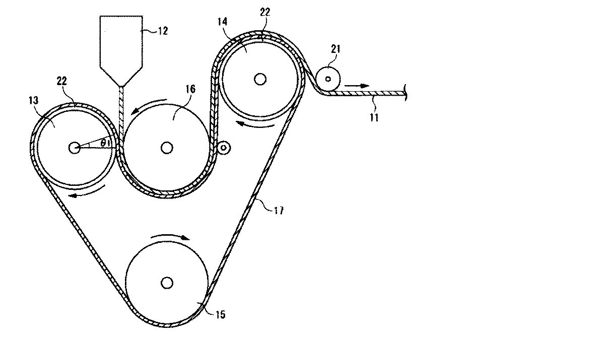
第1の樹脂層を製造するための製造装置の一例を、図1に示す。
図1に示す製造装置は、押出機のTダイ12、第1冷却ロール13、第2冷却ロール14、第3冷却ロール15、第4冷却ロール16、金属製エンドレスベルト17、剥離ロール21を備える。
このように構成された製造装置を用いた急冷によるシート(第1の樹脂層)11の製造方法を以下に説明する。
An example of a manufacturing apparatus for manufacturing the first resin layer is shown in FIG.
The manufacturing apparatus shown in FIG. 1 includes a T die 12 of an extruder, a
A method for manufacturing the sheet (first resin layer) 11 by rapid cooling using the manufacturing apparatus configured as described above will be described below.
まず、押し出された溶融樹脂と直接接触し、これを冷却する金属製エンドレスベルト17及び第4冷却ロール16の表面温度が露点以上、50℃以下、好ましくは30℃以下に保たれるように、予め各冷却ロール13、14、15、16の温度制御を行う。
First, the surface temperature of the metal
ここで、第4冷却ロール16及び金属製エンドレスベルト17の表面温度が露点以下では、表面に結露が生じ均一な製膜が困難になる可能性がある。一方、表面温度が50℃より高いと、得られるシート11の透明性が低くなるとともに、α晶が多くなり、熱成形しにくいものとなる可能性がある。従って、表面温度は例えば20℃である。
Here, if the surface temperature of the
次に、押出機のTダイ12より押し出された溶融樹脂(造核剤を含まない)を第1冷却ロール13上で金属製エンドレスベルト17と、第4冷却ロール16との間に挟み込む。この状態で、溶融樹脂を第1、第4冷却ロール13、16で圧接するとともに、20℃で急冷する。
この際、第1冷却ロール13及び第4冷却ロール16間の押圧力で弾性材22が圧縮されて弾性変形する。
この弾性材22が弾性変形している部分、即ち、第1冷却ロール13の中心角度θ1に対応する円弧部分で、急冷されたシートは各冷却ロール13、16により面状圧接されている。この際の面圧は、通常0.1MPa以上20MPa以下である。
Next, the molten resin (excluding the nucleating agent) extruded from the T die 12 of the extruder is sandwiched between the metal
At this time, the
The rapidly cooled sheet is press-contacted by the cooling rolls 13 and 16 at the portion where the
上述のように圧接され、第4冷却ロール16及び金属製エンドレスベルト17間に挟まれたシートは、続いて、第4冷却ロール16の略下半周に対応する円弧部分で金属製エンドレスベルト17と第4冷却ロール16とに挟まれて面状圧接される。この際の面圧は、通常0.01MPa以上0.5MPa以下である。
The sheet press-contacted as described above and sandwiched between the
このように第4冷却ロール16で面状圧接及び冷却された後、金属製エンドレスベルト17に密着したシートは、金属製エンドレスベルト17の回動とともに第2冷却ロール14上に移動される。ここで、剥離ロール21によりガイドされて第2冷却ロール14側に押圧されたシートは、前述と同様、第2冷却ロール14の略上半周に対応する円弧部分で金属製エンドレスベルト17により面状圧接され、再び30℃以下の温度で冷却される。この際の面圧は、通常0.01MPa以上0.5MPa以下である。
After the sheet pressure contact and cooling by the
第2冷却ロール14上で冷却されたシートは、剥離ロール21により金属製エンドレスベルト17から剥離され、巻き取りロール(図示省略)により、所定の速度で巻き取られる。
The sheet cooled on the
金属層において、金属又は金属酸化物の金属としては、積層体に金属調の意匠を付与できる金属であれば特に限定されないが、例えば、スズ、インジウム、クロム、アルミニウム、ニッケル、銅、銀、金、白金、亜鉛、及びこれらのうち少なくとも1種を含む合金等が挙げられる。これらは、1種単独でも、2種以上を組み合わせてもよい。 In the metal layer, the metal or metal oxide is not particularly limited as long as it is a metal that can impart a metallic design to the laminate, but for example, tin, indium, chromium, aluminum, nickel, copper, silver, gold , Platinum, zinc, and alloys containing at least one of these. These may be used alone or in combination of two or more.
これらの中でも、伸展性の観点と、色調が優れるという観点から、好ましくはインジウム及びアルミニウムが挙げられる。これにより、積層体を三次元成形した際にクラックが発生しにくくなる。 Among these, indium and aluminum are preferable from the viewpoint of extensibility and excellent color tone. This makes it difficult for cracks to occur when the laminate is three-dimensionally formed.
金属層の厚みは、5nm以上80nm以下が好ましく、15nm以上70nm以下が好ましい。5nm未満の場合、所望していた金属光沢が得られなくなるおそれがあり、一方、80nmを超えると、クラックが生じるおそれがある。 The thickness of the metal layer is preferably 5 nm to 80 nm, and more preferably 15 nm to 70 nm. If it is less than 5 nm, the desired metallic luster may not be obtained, while if it exceeds 80 nm, cracks may occur.
金属層の形成方法は、特に制限されないが、質感が高く高級感のある金属調の意匠を積層体に付与する観点から、例えば、上述の金属を用いた、蒸着法、真空蒸着法、スパッタリング法、イオンプレーティング法等が好ましい。特に、真空蒸着法は、低コストで、被蒸着体へのダメージが少ないため、好ましい。蒸着の条件は、用いる金属の溶融温度又は蒸発温度に応じて適宜設定すればよい。また、上記の金属を含むペーストを塗工する方法、上記の金属を用いためっき法等を用いることができる。 The method for forming the metal layer is not particularly limited, but from the viewpoint of imparting a high-quality and high-quality metallic design to the laminate, for example, a vapor deposition method, a vacuum vapor deposition method, or a sputtering method using the above-described metal. An ion plating method or the like is preferable. In particular, the vacuum evaporation method is preferable because it is low cost and causes little damage to the object to be evaporated. The conditions for vapor deposition may be appropriately set according to the melting temperature or evaporation temperature of the metal used. Moreover, the method of coating the paste containing said metal, the plating method using said metal, etc. can be used.
本発明の積層体は、上述の第1の樹脂層、第2の樹脂層及び金属層を、この順に積層したものである。
第1の樹脂層及び第2の樹脂層は、接していてもよい。また、第2の樹脂層及び金属層は接していてもよい。
本発明の積層体は、印刷層、第3の樹脂層、バッキングフィルム等を含んでもよい。
The laminate of the present invention is obtained by laminating the above-described first resin layer, second resin layer, and metal layer in this order.
The first resin layer and the second resin layer may be in contact with each other. Further, the second resin layer and the metal layer may be in contact with each other.
The laminate of the present invention may include a printing layer, a third resin layer, a backing film, and the like.
印刷層は、金属層の、第2の樹脂層と接する面と反対の面、又は金属層と第2の樹脂層との間に、形成されることが好ましい。
印刷層は、一部に形成されてもよく、全面に形成されてもよい。印刷層の形状としては、特に制限されず、ベタ状、カーボン調、木目調等の様々な形状が挙げられる。
The print layer is preferably formed on the surface of the metal layer opposite to the surface in contact with the second resin layer, or between the metal layer and the second resin layer.
The print layer may be formed on a part or the entire surface. The shape of the printing layer is not particularly limited, and various shapes such as a solid shape, a carbon tone, and a woodgrain tone are exemplified.
印刷の方法としては、スクリーン印刷法、オフセット印刷法、グラビア印刷法、ロールコート法、スプレーコート法等の一般的な印刷方法が利用できる。特に、スクリーン印刷法はインキの厚みを厚くできるので、複雑な形状に成形した際にインキ割れが発生しにくいことから好ましい。
例えば、スクリーン印刷の場合、成形時の伸びに優れたインキが好ましく、十条ケミカル株式会社製のFM3107高濃度白やSIM3207高濃度白等が例示できるが、この限りではない。
As a printing method, a general printing method such as a screen printing method, an offset printing method, a gravure printing method, a roll coating method, or a spray coating method can be used. In particular, the screen printing method is preferable because the thickness of the ink can be increased, and therefore, ink cracking hardly occurs when the ink is molded into a complicated shape.
For example, in the case of screen printing, ink excellent in elongation at the time of molding is preferable, and FM3107 high density white, SIM3207 high density white, etc. manufactured by Jujo Chemical Co., Ltd. can be exemplified, but not limited thereto.
第3の樹脂層は、第1の樹脂層の、第2の樹脂層と接する面と反対の面に形成されることが好ましい。第3の樹脂層が存在することで、第1の樹脂層の金属層とは反対側に、印刷層やコーティング層を形成しやすくなる。
第3の樹脂層の樹脂としては、第2の樹脂層の樹脂と同様のものが挙げられる。第3の樹脂層の樹脂は、第2の樹脂層の樹脂と同一であることが好ましい。
The third resin layer is preferably formed on the surface of the first resin layer opposite to the surface in contact with the second resin layer. The presence of the third resin layer makes it easier to form a print layer or a coating layer on the opposite side of the first resin layer from the metal layer.
Examples of the resin of the third resin layer include the same resins as those of the second resin layer. The resin of the third resin layer is preferably the same as the resin of the second resin layer.
第3の樹脂層の厚みは、100nm以上3000nm以下が好ましい。第3の樹脂層の厚みが100nm未満では、スクリーン印刷時のインキの密着性が得られなくなるおそれがある。3000nmを超えるとべた付きが生じてブロッキングの原因となるおそれがある。 The thickness of the third resin layer is preferably 100 nm or more and 3000 nm or less. If the thickness of the third resin layer is less than 100 nm, ink adhesion during screen printing may not be obtained. If it exceeds 3000 nm, stickiness may occur and cause blocking.
第3の樹脂層の、第1の樹脂層と接する面と反対の面には、印刷層やハードコート、反射防止コート、遮熱コート等の各種コーティング層を積層できるが、この限りではない。 Various coating layers such as a printing layer, a hard coat, an antireflection coating, and a thermal barrier coating can be laminated on the surface of the third resin layer opposite to the surface in contact with the first resin layer, but this is not restrictive.
本発明の成形体の製造方法では、上記積層体を、成形し、本発明の成形体を得ることができる。 In the method for producing a molded article of the present invention, the laminate can be molded to obtain the molded article of the present invention.
本発明の成形体は、金属又は金属酸化物がインジウム又は酸化インジウムの場合、光沢度が、250%以上であることが好ましい。より好ましくは300%以上、特に好ましくは330%以上である。
光沢度が250%以上であれば、金属光沢を発現し、優れた金属調の意匠を成形体へ附与できる。
When the metal or metal oxide is indium or indium oxide, the molded article of the present invention preferably has a glossiness of 250% or more. More preferably, it is 300% or more, and particularly preferably 330% or more.
When the glossiness is 250% or more, a metallic luster is exhibited and an excellent metallic design can be imparted to the molded body.
また、本発明の成形体は、金属又は金属酸化物がアルミニウム又は酸化アルミニウムの場合、光沢度が380%以上であることが好ましい。より好ましくは400%以上、特に好ましくは420%以上である。
光沢度が380%以上であれば、金属光沢を発現し、優れた金属調の意匠を成形体へ附与できる。
Moreover, when the metal or metal oxide is aluminum or aluminum oxide, the molded article of the present invention preferably has a glossiness of 380% or more. More preferably, it is 400% or more, and particularly preferably 420% or more.
When the glossiness is 380% or more, a metallic luster is exhibited and an excellent metallic design can be imparted to the molded body.
光沢度の測定については、JIS Z 8741の60度鏡面光沢の測定方法に準拠して測定することができる。
具体的には、自動式測色色差計(AUD−CH−2型−45,60、スガ試験機株式会社製)を使用し、シートに光を入射角60度で照射し、同じく60度で反射光を受光したときの反射光束ψsを測定し、屈折率1.567のガラス表面からの反射光束ψ0sとの比により、下式(1)により、光沢度を求めることができる。
光沢度(Gs)=(ψs/ψ0s)*100 …(1)
About the measurement of glossiness, it can measure based on the measuring method of 60 degree specular glossiness of JISZ8741.
Specifically, an automatic colorimetric color difference meter (AUD-CH-2 type-45, 60, manufactured by Suga Test Instruments Co., Ltd.) was used, and the sheet was irradiated with light at an incident angle of 60 degrees. The reflected luminous flux ψs when the reflected light is received is measured, and the glossiness can be obtained by the following formula (1) based on the ratio with the reflected luminous flux ψ0s from the glass surface having a refractive index of 1.567.
Glossiness (Gs) = (ψs / ψ0s) * 100 (1)
光沢度は、第1の樹脂層の、第2の樹脂層と接する面と反対の面から測定することが好ましい。 The glossiness is preferably measured from the surface of the first resin layer opposite to the surface in contact with the second resin layer.
成形する方法としては、インモールド成形、インサート成形、被覆成形等が挙げられる。 Examples of the molding method include in-mold molding, insert molding, and coating molding.
インモールド成形は、金型内に積層体を設置して、金型内に供給される成形用樹脂の圧力で所望の形状に成形して成形体を得る方法である。
インモールド成形として、積層体を金型に装着し、成形用樹脂を供給して一体化して行うことが好ましい。
In-mold molding is a method in which a laminate is placed in a mold and molded into a desired shape with the pressure of a molding resin supplied into the mold to obtain a molded body.
The in-mold molding is preferably performed by mounting the laminate on a mold and supplying and integrating a molding resin.
インサート成形では、金型内に設置する附形体を予備附形しておき、その形状に成形用樹脂を充填することで、成形体を得る方法である。より複雑な形状を出すことができる。
インサート成形として、積層体を金型に合致するよう附形し、附形した積層体を金型に装着し、成形用樹脂を供給して一体化して行うことが好ましい。
金型に合致するようする附形(予備附形)は、真空成型、圧空成型、真空圧空成型、プレス成型、プラグアシスト成形等で行うことが好ましい。
Insert molding is a method of obtaining a molded body by preliminarily shaping a shaped body to be installed in a mold and filling the shape with a molding resin. More complicated shapes can be produced.
The insert molding is preferably performed by forming the laminated body so as to match the mold, mounting the shaped laminated body on the mold, and supplying and integrating the molding resin.
The attachment (preliminary attachment) that matches the mold is preferably performed by vacuum forming, pressure forming, vacuum / pressure forming, press forming, plug assist forming, or the like.
成形用樹脂は、成形可能な熱可塑性樹脂が好ましい。具体的には、ポリプロピレン、ポリエチレン、ポリカーボネート、アセチレン−スチレン−ブタジエン共重合体、アクリル重合体等が例示できるが、この限りではない。ファイバーやタルク等の無機フィラーを添加してもよい。
供給は、射出で行うことが好ましく、圧力5MPa以上120MPa以下が好ましい。
金型温度は20℃以上90℃以下であることが好ましい。
The molding resin is preferably a moldable thermoplastic resin. Specific examples include polypropylene, polyethylene, polycarbonate, acetylene-styrene-butadiene copolymer, and acrylic polymer, but are not limited thereto. Inorganic fillers such as fiber and talc may be added.
The supply is preferably performed by injection, and the pressure is preferably 5 MPa or more and 120 MPa or less.
The mold temperature is preferably 20 ° C. or higher and 90 ° C. or lower.
被覆成形として、チャンバーボックス内に芯材を配設し、芯材の上方に、積層体を配置し、チャンバーボックス内を減圧し、積層体を加熱軟化し、芯材の上面に、積層体を接触し、加熱軟化させた積層体を芯材に押圧して被覆させることが好ましい。
加熱軟化後、芯材の上面に、積層体を接触させることが好ましい。
押圧は、チャンバーボックス内において、積層体の、芯材と接する側を減圧したまま、積層体の、芯材の反対側を加圧することが好ましい。
As covering molding, a core material is arranged in a chamber box, a laminate is arranged above the core material, the inside of the chamber box is decompressed, the laminate is heated and softened, and the laminate is placed on the upper surface of the core material. It is preferable that the laminated body that has been brought into contact and softened by heating is pressed against the core material to be coated.
After heat softening, it is preferable to bring the laminate into contact with the upper surface of the core material.
In the pressing, it is preferable to pressurize the opposite side of the core of the laminate while reducing the pressure of the side of the laminate that contacts the core in the chamber box.
芯材は、凸状でも凹状であってもよく、例えば三次元曲面を有する樹脂、金属、セラミック等が挙げられる。樹脂は、上述の成形に用いる樹脂と同様のものが挙げられる。 The core material may be convex or concave, and examples thereof include a resin having a three-dimensional curved surface, metal, and ceramic. Examples of the resin include the same resins as those used for the molding described above.
具体的には、互いに分離可能な、上下ふたつの成型室から構成されるチャンバーボックスを用いることが好ましい。
まず、下成型室内のテーブル上へ芯材を載せ、セットする。被成型物である本発明の積層体を下成型室上面にクランプで固定する。この際、上・下成型室内は大気圧である。
次に上成型室を降下させ、上・下成型室を接合させ、チャンバーボックス内を閉塞状態にする。上・下成型室内の両方を大気圧状態から、真空タンクによって真空吸引状態とする。
上・下成型室内を真空吸引状態にした後、ヒータを点けて加飾シートの加熱を行なう。次に上・下成型室内は真空状態のまま下成型室内のテーブルを上昇させる。
次に、上成型室内の真空を開放し大気圧を入れることによって、被成型物である本発明の積層体は芯材へ押し付けられてオーバーレイ(成型)される。尚、上成型室内に圧縮空気を供給することで、より大きな力で被成型物である本発明の積層体を芯材へ密着させることも可能である。
オーバーレイが完了した後、ヒータを消灯し、下成型室内の真空も開放して大気圧状態へ戻し、上成型室を上昇させ、加飾印刷された積層体が表皮材として被覆された製品を取り出す。
Specifically, it is preferable to use a chamber box composed of two upper and lower molding chambers that can be separated from each other.
First, a core material is placed and set on a table in the lower molding chamber. The laminate of the present invention, which is a molding object, is fixed to the upper surface of the lower molding chamber with a clamp. At this time, the upper and lower molding chambers are at atmospheric pressure.
Next, the upper molding chamber is lowered, the upper and lower molding chambers are joined, and the inside of the chamber box is closed. Both the upper and lower molding chambers are brought into the vacuum suction state from the atmospheric pressure state by the vacuum tank.
After the upper and lower molding chambers are evacuated, the heater is turned on and the decorative sheet is heated. Next, the table in the lower molding chamber is raised while the upper and lower molding chambers are in a vacuum state.
Next, by releasing the vacuum in the upper molding chamber and applying atmospheric pressure, the laminate of the present invention, which is a molding object, is pressed against the core material and overlaid (molded). In addition, by supplying compressed air into the upper molding chamber, the laminate of the present invention, which is a molding object, can be brought into close contact with the core material with a greater force.
After the overlay is completed, the heater is turned off, the vacuum in the lower molding chamber is released to return to atmospheric pressure, the upper molding chamber is raised, and the product with the decorative printed laminate coated as the skin material is taken out. .
本発明の積層体及び成形体、並びに本発明の方法で得られる成形体は、デスクトップパソコンやノート型パソコン等のコンピューター部品、携帯電話部品、電気又は電子機器、携帯情報端末、家電製品部品、便座、自動車部品、自動二輪車部品、産業資材及び建築材等に使用することができる。 The laminated body and molded body of the present invention, and the molded body obtained by the method of the present invention are computer parts such as desktop personal computers and notebook personal computers, mobile phone parts, electric or electronic devices, portable information terminals, home appliance parts, toilet seats. It can be used for automobile parts, motorcycle parts, industrial materials and building materials.
実施例1
(1)積層体の製造
図1に示す製造装置を用いた。押出機にポリプロピレン(プライムポリプロF−133A 株式会社プライムポリマー製(メルトフローインデックス3g/10分、ホモポリプロピレン))を投入し、以下の条件で押し出して、第1の樹脂層を得た。
押出機の直径:150mm
Tダイ12の幅:1400mm
厚み:200μm
シート11の引き取り速度:25m/分
第4冷却ロール16及び金属製エンドレスベルト17の表面温度:17℃
冷却速度:10,800℃/分
Example 1
(1) Manufacture of a laminated body The manufacturing apparatus shown in FIG. 1 was used. Polypropylene (Prime Polypro F-133A manufactured by Prime Polymer Co., Ltd. (melt flow index 3 g / 10 min, homopolypropylene)) was charged into the extruder and extruded under the following conditions to obtain a first resin layer.
Extruder diameter: 150mm
Width of T-die 12: 1400mm
Thickness: 200 μm
Take-up speed of sheet 11: 25 m / min Surface temperature of
Cooling rate: 10,800 ° C / min
尚、メルトフローインデックスの測定については、JIS−K7210に準拠して測定した。 In addition, about the measurement of the melt flow index, it measured based on JIS-K7210.
得られた第1の樹脂層にコロナ処理を施し、ウレタン樹脂(ハイドランWLS−202 DIC株式会社製)をバーコーターにて、乾燥後の厚みが49nmとなるように塗布し、80℃にて1分間乾燥して第2の樹脂層を形成した。 The obtained first resin layer was subjected to corona treatment, and a urethane resin (manufactured by Hydran WLS-202 DIC Corporation) was applied with a bar coater so that the thickness after drying was 49 nm. A second resin layer was formed by drying for a minute.
得られた第2の樹脂層の、第1の樹脂層と反対の面に、アルミニウムを50nm蒸着し、金属薄膜(金属又は金属酸化物を含む金属層)を形成し、積層体を得た。 Aluminum was deposited to a thickness of 50 nm on the surface of the obtained second resin layer opposite to the first resin layer to form a metal thin film (metal layer containing a metal or metal oxide) to obtain a laminate.
(2)積層体の評価
得られた積層体の第2の樹脂層の厚みを、反射X線小角散乱法にて測定した。
SmartLab(株式会社リガク製)にて、Cu−Kα線、波長1.5406Å、出力200kV、45mAのX線を使用し、2θ=0.2°から1.5°の範囲のX線の反射強度を測定した。得られた2θとX線の反射強度の曲線から、第2の樹脂層の厚みを算出した。
(2) Evaluation of laminated body The thickness of the 2nd resin layer of the obtained laminated body was measured by the reflection X-ray small angle scattering method.
Using SmartLab (manufactured by Rigaku Corporation), Cu-Kα ray, wavelength 1.5406 mm, output 200 kV, 45 mA X-ray, 2θ = 0.2 ° to 1.5 ° X-ray reflection intensity Was measured. From the obtained 2θ and X-ray reflection intensity curve, the thickness of the second resin layer was calculated.
得られた積層体について、金属層の、第2の樹脂層と接する面と反対の面側に、カッターナイフを用いて、1mm間隔で11本切れ込みを入れた。さらに、その切れ込みと直行するように、1mm間隔で11本切れ込みを入れ、10×10のマスを作った。
市販のセロハンテープ(ニチバン製CT−24(幅24mm))を、上記切れ込みの上に貼り、指の腹でよく密着させたのち、セロハンテープを剥離した。
残ったマスの数を百分率で表し、密着性を評価した。結果を表1に示す。
About the obtained laminated body, 11 notches were made | formed at 1 mm intervals on the surface side opposite to the surface which contact | connects a 2nd resin layer of a metal layer using a cutter knife. In addition, 11 cuts were made at 1 mm intervals to make a 10 × 10 square so as to be perpendicular to the cuts.
A commercially available cellophane tape (CT-24 manufactured by Nichiban (width: 24 mm)) was pasted on the above-mentioned notch, and the cellophane tape was peeled off after closely contacting with the finger pad.
The number of remaining cells was expressed as a percentage, and the adhesion was evaluated. The results are shown in Table 1.
(3)成形体の製造
得られた積層体について、真空圧空成形機FM−3M/H(株式会社ミノス製)を用いて、真空圧空成形により熱成形し、成形体を得た。
(3) Manufacture of a molded object About the obtained laminated body, it thermoformed by vacuum pressure forming using the vacuum pressure forming machine FM-3M / H (made by Minos Co., Ltd.), and obtained the molded object.
(4)成形体の評価
得られた成形体の外観を評価した。
クラックについて、金属光沢を発現する場合を◎、金属光沢は残っているが低下している場合を○、金属光沢が失われている場合を×とし、目視にて評価した。結果を表1に示す。
レインボーについて、レインボーが発生していない場合を○、発生している場合を×とし、目視にて評価した。結果を表1に示す。
(4) Evaluation of molded body The appearance of the obtained molded body was evaluated.
Regarding the crack, the case where the metallic luster was developed was evaluated as ◎, the case where the metallic luster remained but decreased, the case where the metallic luster was lost, and the case where the metallic luster was lost were evaluated as x. The results are shown in Table 1.
With respect to the rainbow, the case where no rainbow was generated was evaluated as ○, and the case where the rainbow was generated was evaluated as visual. The results are shown in Table 1.
また、得られた成形体について、JIS Z 8741の60度鏡面光沢の測定方法に準拠し、自動式測色色差計(AUD−CH−2型−45,60、スガ試験機株式会社製)を使用し、第1の樹脂層の、第2の樹脂層と接する面と反対の面から、光を入射角60度で照射し、同じく60度で反射光を受光したときの反射光束ψsを測定し、屈折率1.567のガラス表面からの反射光束ψ0sとの比により、下式(1)により、光沢度を求めた。結果を表1に示す。
光沢度(Gs)=(ψs/ψ0s)*100 …(1)
Moreover, based on the measuring method of 60 degree specular gloss of JIS Z8741, about the obtained molded object, an automatic colorimetric color difference meter (AUD-CH-2 type-45,60, made by Suga Test Instruments Co., Ltd.) Used to measure the reflected luminous flux ψs when the first resin layer is irradiated with light from the surface opposite to the surface in contact with the second resin layer at an incident angle of 60 degrees and the reflected light is received at 60 degrees. Then, the glossiness was determined by the following formula (1) based on the ratio to the reflected light beam ψ0s from the glass surface having a refractive index of 1.567. The results are shown in Table 1.
Glossiness (Gs) = (ψs / ψ0s) * 100 (1)
(5)第2の樹脂層の樹脂の評価
第2の樹脂層の引張破断伸度については、ガラス基板上に、上記ウレタン樹脂をバーコーターにて塗布し、80℃にて1分間乾燥し、その後分離して厚み150μmの試料を作成し、JIS K7311に準拠した方法で測定した。第2の樹脂層のウレタン樹脂の引張破断伸度は600%であった。
第2の樹脂層の軟化温度を、上記と同様に作成した試料を用いて、高化式フローテスターによる流動開始温度を測定し求めた。第2の樹脂層のウレタン樹脂の軟化温度は160℃であった。
第2の樹脂層について、上記と同様に作成した試料を用いて、示差走査熱量計DSC−7(パーキンエルマージャパン株式会社製)により、以下の条件で示差走査熱分析曲線を測定し、ガラス転移点を求めた。第2の樹脂層のウレタン樹脂のガラス転移点は−50℃であった。
測定開始温度:−90℃
測定終了温度:220℃
昇温温度:10℃/分
(5) Evaluation of resin of second resin layer For the tensile elongation at break of the second resin layer, the urethane resin was applied on a glass substrate with a bar coater and dried at 80 ° C. for 1 minute. Thereafter, the sample was separated to prepare a sample having a thickness of 150 μm and measured by a method in accordance with JIS K7311. The tensile elongation at break of the urethane resin of the second resin layer was 600%.
The softening temperature of the second resin layer was determined by measuring the flow start temperature using a Koka flow tester using a sample prepared in the same manner as described above. The softening temperature of the urethane resin of the second resin layer was 160 ° C.
About the 2nd resin layer, using the sample created similarly to the above, a differential scanning calorimeter DSC-7 (made by Perkin Elmer Japan Co., Ltd.) measured a differential scanning calorimetry curve on the following conditions, and glass transition I asked for a point. The glass transition point of the urethane resin of the second resin layer was −50 ° C.
Measurement start temperature: -90 ° C
Measurement end temperature: 220 ° C
Temperature rising temperature: 10 ° C / min
実施例2
第2の樹脂層の厚みを55nmとした以外は、実施例1と同様に積層体及び成形体を製造し、評価した。結果を表1に示す。
Example 2
A laminate and a molded body were produced and evaluated in the same manner as in Example 1 except that the thickness of the second resin layer was 55 nm. The results are shown in Table 1.
実施例3
アルミニウムに代えて、インジウムを30nm蒸着した以外は、実施例1と同様に積層体及び成形体を製造し、評価した。結果を表1に示す。
Example 3
A laminated body and a molded body were produced and evaluated in the same manner as in Example 1 except that indium was deposited by 30 nm in place of aluminum. The results are shown in Table 1.
実施例4
第2の樹脂層の厚みを55nmとした以外は、実施例3と同様に積層体及び成形体を製造し、評価した。結果を表1に示す。
Example 4
A laminate and a molded body were produced and evaluated in the same manner as in Example 3 except that the thickness of the second resin layer was 55 nm. The results are shown in Table 1.
比較例1
第2の樹脂層の厚みを28nmとした以外は、実施例1と同様に積層体及び成形体を製造し、評価した。結果を表1に示す。
Comparative Example 1
A laminate and a molded body were produced and evaluated in the same manner as in Example 1 except that the thickness of the second resin layer was 28 nm. The results are shown in Table 1.
比較例2
第2の樹脂層の厚みを76nmとした以外は、実施例1と同様に積層体及び成形体を製造し、評価した。結果を表1に示す。
Comparative Example 2
A laminate and a molded body were produced and evaluated in the same manner as in Example 1 except that the thickness of the second resin layer was 76 nm. The results are shown in Table 1.
比較例3
第2の樹脂層の厚みを230nmとした以外は、実施例1と同様に積層体及び成形体を製造し、評価した。結果を表1に示す。
Comparative Example 3
A laminate and a molded body were produced and evaluated in the same manner as in Example 1 except that the thickness of the second resin layer was 230 nm. The results are shown in Table 1.
比較例4
第2の樹脂層の厚みを230nmとした以外は、実施例3と同様に積層体及び成形体を製造し、評価した。結果を表1に示す。
Comparative Example 4
A laminate and a molded body were produced and evaluated in the same manner as in Example 3 except that the thickness of the second resin layer was 230 nm. The results are shown in Table 1.
本発明の積層体及び成形体、並びに本発明の方法で得られる成形体は、デスクトップパソコンやノート型パソコン等のコンピューター部品、携帯電話部品、電気又は電子機器、携帯情報端末、家電製品部品、自動車部品、産業資材及び建築材等に使用することができる。 The laminated body and molded body of the present invention, and the molded body obtained by the method of the present invention are computer parts such as desktop personal computers and notebook personal computers, mobile phone parts, electric or electronic devices, portable information terminals, home appliance parts, automobiles. It can be used for parts, industrial materials and building materials.
11 シート
12 Tダイ
13 第1冷却ロール
14 第2冷却ロール
15 第3冷却ロール
16 第4冷却ロール
17 金属製エンドレスベルト
21 剥離ロール
22 弾性材
DESCRIPTION OF SYMBOLS 11 Sheet | seat 12 T die 13
Claims (15)
第2の樹脂層、及び
金属又は金属酸化物を含む金属層を、この順に含む積層体であって、
前記第2の樹脂層の厚みが35nm以上70nm以下であり、前記第2の樹脂層の樹脂と前記第1の樹脂層の樹脂が同一でない積層体。 A first resin layer comprising a thermoplastic resin;
A laminate including a second resin layer and a metal layer containing a metal or metal oxide in this order,
A laminate in which the thickness of the second resin layer is not less than 35 nm and not more than 70 nm, and the resin of the second resin layer and the resin of the first resin layer are not the same.
チャンバーボックス内に芯材を配設し、
前記芯材の上方に、前記積層体を配置し、
前記チャンバーボックス内を減圧し、
前記積層体を加熱軟化し、
加熱軟化させた前記積層体を前記芯材に押圧して被覆させる請求項12に記載の成形体の製造方法。 The molding is
A core material is arranged in the chamber box,
Arrange the laminated body above the core material,
Depressurizing the inside of the chamber box,
Heat softening the laminate,
The manufacturing method of the molded object of Claim 12 which presses and coat | covers the said laminated body heat-softened on the said core material.
Applications Claiming Priority (2)
| Application Number | Priority Date | Filing Date | Title |
|---|---|---|---|
| JP2016030212 | 2016-02-19 | ||
| JP2016030212 | 2016-02-19 |
Publications (2)
| Publication Number | Publication Date |
|---|---|
| JP2017149144A true JP2017149144A (en) | 2017-08-31 |
| JP6963392B2 JP6963392B2 (en) | 2021-11-10 |
Family
ID=59740305
Family Applications (1)
| Application Number | Title | Priority Date | Filing Date |
|---|---|---|---|
| JP2017027564A Active JP6963392B2 (en) | 2016-02-19 | 2017-02-17 | Laminated body, molded body and manufacturing method of molded body |
Country Status (1)
| Country | Link |
|---|---|
| JP (1) | JP6963392B2 (en) |
Cited By (2)
| Publication number | Priority date | Publication date | Assignee | Title |
|---|---|---|---|---|
| WO2018151089A1 (en) * | 2017-02-14 | 2018-08-23 | 出光ユニテック株式会社 | Laminate, molded article, and method for producing molded article |
| WO2022080084A1 (en) * | 2020-10-16 | 2022-04-21 | 出光ユニテック株式会社 | Resin sheet, laminate, molded body, and method for producing molded body |
Citations (5)
| Publication number | Priority date | Publication date | Assignee | Title |
|---|---|---|---|---|
| JPH05116246A (en) * | 1991-10-28 | 1993-05-14 | Dainippon Printing Co Ltd | Manufacture of composite sheet of film with metallic deposit and paper |
| JP2001310414A (en) * | 2000-04-28 | 2001-11-06 | Nissha Printing Co Ltd | Lustrous decorating sheet and method for manufacturing lustrous decorating molding |
| JP2006272658A (en) * | 2005-03-28 | 2006-10-12 | Shin Etsu Polymer Co Ltd | Metallic tone sheet, metallic tone shaped body and its manufacturing method |
| WO2012057072A1 (en) * | 2010-10-26 | 2012-05-03 | 東洋紡績株式会社 | Polyester film for use in molding |
| JP2014198414A (en) * | 2013-03-29 | 2014-10-23 | 出光ユニテック株式会社 | Laminate, molded body, molded product and method for producing molded product |
-
2017
- 2017-02-17 JP JP2017027564A patent/JP6963392B2/en active Active
Patent Citations (5)
| Publication number | Priority date | Publication date | Assignee | Title |
|---|---|---|---|---|
| JPH05116246A (en) * | 1991-10-28 | 1993-05-14 | Dainippon Printing Co Ltd | Manufacture of composite sheet of film with metallic deposit and paper |
| JP2001310414A (en) * | 2000-04-28 | 2001-11-06 | Nissha Printing Co Ltd | Lustrous decorating sheet and method for manufacturing lustrous decorating molding |
| JP2006272658A (en) * | 2005-03-28 | 2006-10-12 | Shin Etsu Polymer Co Ltd | Metallic tone sheet, metallic tone shaped body and its manufacturing method |
| WO2012057072A1 (en) * | 2010-10-26 | 2012-05-03 | 東洋紡績株式会社 | Polyester film for use in molding |
| JP2014198414A (en) * | 2013-03-29 | 2014-10-23 | 出光ユニテック株式会社 | Laminate, molded body, molded product and method for producing molded product |
Cited By (4)
| Publication number | Priority date | Publication date | Assignee | Title |
|---|---|---|---|---|
| WO2018151089A1 (en) * | 2017-02-14 | 2018-08-23 | 出光ユニテック株式会社 | Laminate, molded article, and method for producing molded article |
| JPWO2018151089A1 (en) * | 2017-02-14 | 2019-12-19 | 出光ユニテック株式会社 | Laminate, molded article and method for producing molded article |
| JP7073282B2 (en) | 2017-02-14 | 2022-05-23 | 出光ユニテック株式会社 | Laminated body, molded body and manufacturing method of molded body |
| WO2022080084A1 (en) * | 2020-10-16 | 2022-04-21 | 出光ユニテック株式会社 | Resin sheet, laminate, molded body, and method for producing molded body |
Also Published As
| Publication number | Publication date |
|---|---|
| JP6963392B2 (en) | 2021-11-10 |
Similar Documents
| Publication | Publication Date | Title |
|---|---|---|
| JP7073282B2 (en) | Laminated body, molded body and manufacturing method of molded body | |
| JP6837453B2 (en) | Laminated body, molded body using the laminated body and its manufacturing method | |
| JP6963392B2 (en) | Laminated body, molded body and manufacturing method of molded body | |
| WO2014157320A1 (en) | Laminated body, molded body, molded product, and method for manufacturing molded product | |
| JP6037919B2 (en) | LAMINATE, MOLDED BODY, MOLDED BODY, AND METHOD FOR PRODUCING MOLDED BODY | |
| JP2014198416A (en) | Molded product and method for producing the same | |
| JP6779095B2 (en) | Manufacturing method of shaping decorative sheet | |
| JP7019615B2 (en) | Laminated body, decorative sheet, manufacturing method of laminated body, manufacturing method of molded body and molded body | |
| JP7297686B2 (en) | RESIN SHEET, LAMINATED BODY, MOLDED BODY, AND METHOD FOR MANUFACTURING MOLDED BODY | |
| JPWO2019054397A1 (en) | Laminated body, molded body and manufacturing method of molded body | |
| JP2016141745A (en) | Resin sheet, molded product, method for producing resin sheet and method for producing molded product | |
| JP2017110081A (en) | Resin sheet, laminated sheet, molding, molded article and method for producing the same | |
| WO2022190957A1 (en) | Layered body, molded body, and method for producing molded body | |
| WO2021124943A1 (en) | Layered body, molded article, and method for producing molded article | |
| WO2022080084A1 (en) | Resin sheet, laminate, molded body, and method for producing molded body | |
| JP6514473B2 (en) | LAMINATE, MOLDED BODY, MOLDED ARTICLE, AND METHOD FOR PRODUCING MOLDED ARTICLE | |
| JP2018024247A (en) | Decorative film and method for producing decorative molded body using the same | |
| WO2021145331A1 (en) | Laminate, molded body, and molded body manufacturing method | |
| JP2017206587A (en) | Resin sheet, laminate, molding, method for producing molding, vehicular exterior part and interior material fabricated with molding, and cabinet of household electrical appliance and the like | |
| JP2000033676A (en) | Laminated film or sheet, its production, laminated structure and its use | |
| JP2023067235A (en) | Resin sheet, laminate, molded article, and method for manufacturing molded article | |
| JP2021130306A (en) | Laminate, molding and method for producing molding | |
| JP2020189443A (en) | Multilayer film, decorative sheet, decorative molded body, method for manufacturing multilayer film, and method for manufacturing decorative sheet | |
| JP4906989B2 (en) | Manufacturing method of sheet for simultaneous injection molding | |
| JP2000033677A (en) | Structure having high grade appearance, and its production and use |
Legal Events
| Date | Code | Title | Description |
|---|---|---|---|
| A621 | Written request for application examination |
Free format text: JAPANESE INTERMEDIATE CODE: A621 Effective date: 20191127 |
|
| A977 | Report on retrieval |
Free format text: JAPANESE INTERMEDIATE CODE: A971007 Effective date: 20200826 |
|
| A131 | Notification of reasons for refusal |
Free format text: JAPANESE INTERMEDIATE CODE: A131 Effective date: 20200923 |
|
| A521 | Request for written amendment filed |
Free format text: JAPANESE INTERMEDIATE CODE: A523 Effective date: 20201113 |
|
| A131 | Notification of reasons for refusal |
Free format text: JAPANESE INTERMEDIATE CODE: A131 Effective date: 20210330 |
|
| A521 | Request for written amendment filed |
Free format text: JAPANESE INTERMEDIATE CODE: A523 Effective date: 20210527 |
|
| TRDD | Decision of grant or rejection written | ||
| A01 | Written decision to grant a patent or to grant a registration (utility model) |
Free format text: JAPANESE INTERMEDIATE CODE: A01 Effective date: 20210921 |
|
| A61 | First payment of annual fees (during grant procedure) |
Free format text: JAPANESE INTERMEDIATE CODE: A61 Effective date: 20211015 |
|
| R150 | Certificate of patent or registration of utility model |
Ref document number: 6963392 Country of ref document: JP Free format text: JAPANESE INTERMEDIATE CODE: R150 |