JP2017206587A - Resin sheet, laminate, molding, method for producing molding, vehicular exterior part and interior material fabricated with molding, and cabinet of household electrical appliance and the like - Google Patents
Resin sheet, laminate, molding, method for producing molding, vehicular exterior part and interior material fabricated with molding, and cabinet of household electrical appliance and the like Download PDFInfo
- Publication number
- JP2017206587A JP2017206587A JP2016098253A JP2016098253A JP2017206587A JP 2017206587 A JP2017206587 A JP 2017206587A JP 2016098253 A JP2016098253 A JP 2016098253A JP 2016098253 A JP2016098253 A JP 2016098253A JP 2017206587 A JP2017206587 A JP 2017206587A
- Authority
- JP
- Japan
- Prior art keywords
- resin layer
- resin
- laminate
- molding
- layer
- Prior art date
- Legal status (The legal status is an assumption and is not a legal conclusion. Google has not performed a legal analysis and makes no representation as to the accuracy of the status listed.)
- Ceased
Links
Images
Abstract
Description
本発明は、樹脂シート、積層体、成形体、成形体の製造方法、及びその成形体を用いて作成された鞍乗型車両の外装部品、四輪車の外装部品、車両の内装材、家電の筐体、化粧鋼鈑、化粧板、住宅設備及び情報通信機器の筐体に関する。 The present invention relates to a resin sheet, a laminate, a molded body, a method for manufacturing the molded body, and an exterior part for a saddle-ride type vehicle, an exterior part for a four-wheeled vehicle, an interior material for a vehicle, and a household appliance, The present invention relates to a case, a decorative steel plate, a decorative plate, a housing facility, and a case of an information communication device.
二輪車や四輪車等の輸送機器は、走行中に泥等の汚れが外装(成形体)に付着して汚れてしまう課題がある。特に、二輪車では、雨天時の走行によってマッドカバーに泥が付着し、重量が増して走行性能が低下する課題がある。
汚れの付着を抑制するために、成形体の表面にオイルを塗布する方法や、樹脂中に離形成分を練り込んでブリードアウトさせる方法等が検討されている。しかし、これらの方法では、成形体表面の有効成分が落ちやすいため、泥が次第に付着しやすくなるという問題があった。
Transportation equipment such as two-wheeled vehicles and four-wheeled vehicles has a problem that dirt such as mud adheres to the exterior (molded body) during traveling. In particular, two-wheeled vehicles have a problem that mud adheres to the mud cover due to running in rainy weather, the weight increases, and the running performance deteriorates.
In order to suppress the adhesion of dirt, a method of applying oil to the surface of a molded body, a method of kneading a part formed in a resin and bleeding out, and the like have been studied. However, these methods have a problem that mud tends to adhere gradually because the active ingredients on the surface of the molded body are likely to fall off.
特許文献1には、離形層が少なくともポリオレフィン系樹脂とシリコーン化合物を含有する積層体が開示されている。
特許文献2には、シリル化ポリオレフィンを含む撥水フィルムの技術が開示されている。
Patent Document 1 discloses a laminate in which the release layer contains at least a polyolefin resin and a silicone compound.
Patent Document 2 discloses a technique for a water-repellent film containing a silylated polyolefin.
しかしながら、従来の成形体は未だ防汚性が十分ではなかった。本発明の目的は、防汚性に優れる成形体を提供することである。 However, conventional molded articles still have insufficient antifouling properties. The objective of this invention is providing the molded object which is excellent in antifouling property.
本発明者らが鋭意検証した結果、成形体表面の平滑性が防汚性に大きく影響することを見出した。この知見に基づき、成形体表面がシリコーン−オレフィン共重合体を含み、かつ平滑であれば、汚れが付着しにくく、優れた防汚性を発揮できることを見出し、本発明を完成した。
本発明によれば、以下の樹脂シート等が提供される。
1.ポリオレフィン及びシリコーン−オレフィン共重合体を含む樹脂シートであって、表面及び裏面の少なくとも一方の算術平均粗さRaが0.15μm以下である樹脂シート。
2.ポリオレフィン及びシリコーン−オレフィン共重合体を含む樹脂シートであって、表面及び裏面の少なくとも一方の静摩擦係数が0.4以下である樹脂シート。
3.1に記載の樹脂シートからなる第1の樹脂層、及び第2の樹脂層を含む積層体であって、
前記第1の樹脂層の、前記第2の樹脂層と反対側の面の算術平均粗さRaが0.15μm以下である積層体。
4.2に記載の樹脂シートからなる第1の樹脂層、及び第2の樹脂層を含む積層体であって、
前記第1の樹脂層の、前記第2の樹脂層と反対側の面の静摩擦係数が0.4以下である積層体。
5.前記第1の樹脂層に含まれるポリオレフィンが、ポリプロピレン、ポリエチレン、又はポリプロピレン及びポリエチレンである3又は4に記載の積層体。
6.前記第2の樹脂層がポリオレフィンを含む3〜5のいずれかに記載の積層体。
7.前記第2の樹脂層のポリオレフィンが、ポリプロピレン、ポリエチレン、又はポリプロピレン及びポリエチレンである6に記載の積層体。
8.前記第2の樹脂層の、前記第1の樹脂層と反対側の面に第3の樹脂層を含み、前記第3の樹脂層が、ウレタン樹脂、アクリル樹脂、ポリオレフィン及びポリエステルから選択される1以上の樹脂を含む3〜7のいずれかに記載の積層体。
9.前記第3の樹脂層の、前記第2の樹脂層と反対側の面の一部又は全面に印刷層を含む8に記載の積層体。
10.前記第3の樹脂層の、前記第2の樹脂層と反対側の面に、金属又は金属酸化物からなる金属層を含む8に記載の積層体。
11.前記金属又は金属酸化物が、スズ、インジウム、クロム、アルミニウム、ニッケル、銅、銀、金、白金及び亜鉛から選択される1以上の金属又はその酸化物を含む10に記載の積層体。
12.前記金属又は金属酸化物が、インジウム及びアルミニウムから選択される1以上の金属又はその酸化物を含む10又は11に記載の積層体。
13.前記金属層の、前記第3の樹脂層と反対側の面の一部又は全面に印刷層を含む10〜12のいずれかに記載の積層体。
14.前記第2の樹脂層の、前記第1の樹脂層と反対側の面の一部又は全面に印刷層を含む3〜7のいずれかに積層体。
15.前記印刷層の、前記第2の樹脂層と反対側の面に金属又は金属酸化物からなる金属層を含む14に記載の積層体。
16.前記金属又は金属酸化物が、スズ、インジウム、クロム、アルミニウム、ニッケル、銅、銀、金、白金及び亜鉛から選択される1以上の金属又はその酸化物を含む15に記載の積層体。
17.前記金属又は金属酸化物が、インジウム及びアルミニウムから選択される1以上の金属又はその酸化物を含む15又は16に記載の積層体。
18.3〜17のいずれかに記載の積層体の成形体。
19.前記第1の樹脂層からなる面の算術平均粗さRaが0.15μm以下である18に記載の成形体。
20.前記第1の樹脂層からなる面の静摩擦係数が0.4以下である18に記載の成形体。
21.3〜17のいずれかに記載の積層体を成形し、成形体を得る成形体の製造方法。
22.前記成形を、前記積層体を金型に装着し、成形用樹脂を供給して一体化して行う21に記載の成形体の製造方法。
23.前記成形を、前記積層体を金型に合致するよう附形し、前記附形した積層体を金型に装着し、成形用樹脂を供給して一体化して行う21に記載の成形体の製造方法。
24.前記成形を、
チャンバーボックス内に芯材を配設し、
前記芯材の上方に、前記積層体を配置し、
前記チャンバーボックス内を減圧し、
前記積層体を加熱軟化し、
加熱軟化させた前記積層体を前記芯材に押圧して被覆させる21に記載の成形体の製造方法。
25.18〜20のいずれかに記載の成形体を用いて作成された、鞍乗型車両の外装部品又は四輪車の外装部品。
26.18〜20のいずれかに記載の成形体を用いて作成された、車両の内装材、家電の筐体、化粧鋼鈑、化粧板、住宅設備又は情報通信機器の筐体。
As a result of earnest verification by the present inventors, it has been found that the smoothness of the surface of the molded product greatly affects the antifouling property. Based on this finding, the present inventors have found that if the surface of the molded body contains a silicone-olefin copolymer and is smooth, it is difficult for dirt to adhere, and excellent antifouling properties can be exhibited, thereby completing the present invention.
According to the present invention, the following resin sheets and the like are provided.
1. A resin sheet comprising a polyolefin and a silicone-olefin copolymer, wherein the arithmetic average roughness Ra of at least one of the front surface and the back surface is 0.15 μm or less.
2. A resin sheet comprising a polyolefin and a silicone-olefin copolymer, wherein the static friction coefficient of at least one of the front surface and the back surface is 0.4 or less.
A laminate including a first resin layer and a second resin layer made of the resin sheet described in 3.1,
The laminated body whose arithmetic mean roughness Ra of the surface on the opposite side to the said 2nd resin layer of the said 1st resin layer is 0.15 micrometer or less.
A laminate including the first resin layer and the second resin layer made of the resin sheet described in 4.2,
The laminated body whose static friction coefficient of the surface on the opposite side to the said 2nd resin layer of the said 1st resin layer is 0.4 or less.
5. The laminate according to 3 or 4, wherein the polyolefin contained in the first resin layer is polypropylene, polyethylene, or polypropylene and polyethylene.
6). The laminated body in any one of 3-5 in which a said 2nd resin layer contains polyolefin.
7). The laminate according to 6, wherein the polyolefin of the second resin layer is polypropylene, polyethylene, or polypropylene and polyethylene.
8). The second resin layer includes a third resin layer on a surface opposite to the first resin layer, and the third resin layer is selected from urethane resin, acrylic resin, polyolefin and polyester The laminated body in any one of 3-7 containing the above resin.
9. 9. The laminate according to 8, wherein the third resin layer includes a printing layer on a part of or the entire surface on the side opposite to the second resin layer.
10. 9. The laminate according to 8, wherein the third resin layer includes a metal layer made of a metal or a metal oxide on a surface opposite to the second resin layer.
11. 11. The laminate according to 10, wherein the metal or metal oxide includes one or more metals selected from tin, indium, chromium, aluminum, nickel, copper, silver, gold, platinum, and zinc, or an oxide thereof.
12 The laminate according to 10 or 11, wherein the metal or metal oxide includes one or more metals selected from indium and aluminum or an oxide thereof.
13. The laminate according to any one of 10 to 12, wherein the metal layer includes a printed layer on a part of or the entire surface on the side opposite to the third resin layer.
14 A laminated body in any one of 3-7 including a printing layer in a part or whole surface of the said 2nd resin layer on the opposite side to the said 1st resin layer.
15. 15. The laminate according to 14, wherein the printed layer includes a metal layer made of a metal or a metal oxide on a surface opposite to the second resin layer.
16. 16. The laminate according to 15, wherein the metal or metal oxide includes one or more metals selected from tin, indium, chromium, aluminum, nickel, copper, silver, gold, platinum, and zinc, or oxides thereof.
17. The laminate according to 15 or 16, wherein the metal or metal oxide includes one or more metals selected from indium and aluminum or an oxide thereof.
18. A molded body of the laminate according to any one of 1 to 17.
19. 19. The molded body according to 18, wherein the arithmetic average roughness Ra of the surface made of the first resin layer is 0.15 μm or less.
20. 19. The molded product according to 18, wherein the surface of the first resin layer has a static friction coefficient of 0.4 or less.
The manufacturing method of the molded object which shape | molds the laminated body in any one of 21.3-17, and obtains a molded object.
22. 22. The method for producing a molded body according to 21, wherein the molding is performed by attaching the laminated body to a mold and supplying and integrating a molding resin.
23. The manufacturing of the molded body according to 21, wherein the molding is performed by shaping the laminated body so as to match a mold, mounting the shaped laminated body on a mold, and supplying and integrating a molding resin. Method.
24. The molding,
A core material is arranged in the chamber box,
Arrange the laminated body above the core material,
Depressurizing the inside of the chamber box,
Heat softening the laminate,
The manufacturing method of the molded object of 21 which presses and coat | covers the said laminated body heat-softened to the said core material.
An exterior part for a saddle-ride type vehicle or an exterior part for a four-wheeled vehicle, which is created using the molded body according to any one of 25.18 to 20.
26. A vehicle interior material, a housing for home appliances, a decorative steel plate, a decorative board, a housing facility, or a housing for an information communication device, created using the molded body according to any one of 26.18 to 20.
本発明によれば、防汚性に優れる成形体が提供できる。 ADVANTAGE OF THE INVENTION According to this invention, the molded object which is excellent in antifouling property can be provided.
[樹脂シート]
本発明の第1の樹脂シートは、ポリオレフィン及びシリコーン−オレフィン共重合体を含む。また、樹脂シートの表面及び裏面の少なくとも一方の面の算術平均粗さRaは0.15μm以下である。
[Resin sheet]
The first resin sheet of the present invention contains a polyolefin and a silicone-olefin copolymer. The arithmetic average roughness Ra of at least one of the front and back surfaces of the resin sheet is 0.15 μm or less.
ポリオレフィンとしては、ポリエチレン、ポリプロピレン、環状ポリオレフィン樹脂等が挙げられるが、特に、耐熱性、硬度の観点からポリプロピレンが好ましい。
ポリプロピレンは、少なくともプロピレンに由来する構造単位を含む重合体である。具体的には、ホモポリプロピレン、プロピレンと他のオレフィン(エチレン等)との共重合体が挙げられる。ポリプロピレンにポリエチレン等のポリオレフィンや共重合体が混合された混合物としてもよい。
ポリプロピレン共重合体は、ランダムポリプロピレン、又はブロックポリプロピレンであってもよく、これらの混合物でもよい。
これらは、1種単独で、又は2種以上を組み合わせて用いてもよい。
Examples of the polyolefin include polyethylene, polypropylene, and cyclic polyolefin resin. In particular, polypropylene is preferable from the viewpoint of heat resistance and hardness.
Polypropylene is a polymer containing at least a structural unit derived from propylene. Specific examples include homopolypropylene and copolymers of propylene and other olefins (such as ethylene). It is good also as a mixture with which polyolefin and copolymers, such as polyethylene, and polypropylene were mixed.
The polypropylene copolymer may be random polypropylene, block polypropylene, or a mixture thereof.
These may be used alone or in combination of two or more.
ポリプロピレンには、必要に応じて、顔料、酸化防止剤、安定剤、紫外線吸収剤等の添加剤を配合してもよい。
また、ポリプロピレンやポリエチレン等のポリオレフィンを、例えば、無水マレイン酸、マレイン酸ジメチル、マレイン酸ジエチル、アクリル酸、メタクリル酸、テトラヒドロフタル酸、グリシジルメタクリレート、ヒドロキシエチルメタクリレート、メチルメタクリレート等の変性用化合物で変性して得られる変性ポリオレフィン樹脂を配合してもよい。
You may mix | blend an additive, such as a pigment, antioxidant, a stabilizer, a ultraviolet absorber, with a polypropylene as needed.
Further, polyolefins such as polypropylene and polyethylene are modified with a modifying compound such as maleic anhydride, dimethyl maleate, diethyl maleate, acrylic acid, methacrylic acid, tetrahydrophthalic acid, glycidyl methacrylate, hydroxyethyl methacrylate, methyl methacrylate, etc. You may mix | blend the modified polyolefin resin obtained by doing.
シリコーン−オレフィン共重合体は、シリコーン(シロキサン結合を有する高分子化合物)とオレフィン(又はポリオレフィン)との共重合体である。
シリコーンは、好ましくは下記式(1)で表される構造単位を有する。

Y1は、O、S又はNR(Rは水素原子又は炭化水素基を表す)を表す。)
The silicone-olefin copolymer is a copolymer of silicone (polymer compound having a siloxane bond) and olefin (or polyolefin).
Silicone preferably has a structural unit represented by the following formula (1).
Y 1 represents O, S or NR (R represents a hydrogen atom or a hydrocarbon group). )
ハロゲン原子としては、フッ素、塩素、臭素、ヨウ素が挙げられる。
炭化水素基としては、アルキル基、アルケニル基、アリール基が挙げられる。
アルキル基としては、メチル基、エチル基、n−プロピル基、イソプロピル基、n−ブチル基、イソブチル基、tert−ブチル基、ヘキシル基、2−エチルヘキシル基、オクチル基、デシル基、オクタデシル基等の直鎖状又は分岐状アルキル基;シクロペンチル基、シクロヘキシル基、ノルボルニル基等のシクロアルキル基;ベンジル基、フェニルエチル基、フェニルプロピル基等のアリールアルキル基が挙げられる。
Examples of the halogen atom include fluorine, chlorine, bromine and iodine.
Examples of the hydrocarbon group include an alkyl group, an alkenyl group, and an aryl group.
Examples of the alkyl group include methyl group, ethyl group, n-propyl group, isopropyl group, n-butyl group, isobutyl group, tert-butyl group, hexyl group, 2-ethylhexyl group, octyl group, decyl group, and octadecyl group. Examples include linear or branched alkyl groups; cycloalkyl groups such as cyclopentyl group, cyclohexyl group, norbornyl group; and arylalkyl groups such as benzyl group, phenylethyl group, and phenylpropyl group.
アルケニル基としては、ビニル基、プロペニル基、シクロヘキセニル基等が挙げられる。
アリール基としては、フェニル基、トリル基、ジメチルフェニル基、トリメチルフェニル基、エチルフェニル基、プロピルフェニル基、ビフェニル基、ナフチル基、メチルナフチル基、アントリル基、フェナントリル基等が挙げられる。
Examples of the alkenyl group include a vinyl group, a propenyl group, and a cyclohexenyl group.
Examples of the aryl group include phenyl group, tolyl group, dimethylphenyl group, trimethylphenyl group, ethylphenyl group, propylphenyl group, biphenyl group, naphthyl group, methylnaphthyl group, anthryl group, phenanthryl group and the like.
酸素含有基としては、アルコキシ基、アリールオキシ基が挙げられる。
アルコキシ基としては、メトキシ基、エトキシ基、プロポキシ基、ブトキシ基、ヘキシルオキシ基、オクチルオキシ基、ベンジルオキシ基、2−フェニルエトキシ基等が挙げられる。
アリールオキシ基としては、フェノキシ基、トリルオキシ基、ビフェニルオキシ基、ナフチルオキシ基等が挙げられる。
Examples of the oxygen-containing group include an alkoxy group and an aryloxy group.
Examples of the alkoxy group include a methoxy group, an ethoxy group, a propoxy group, a butoxy group, a hexyloxy group, an octyloxy group, a benzyloxy group, and a 2-phenylethoxy group.
Examples of the aryloxy group include a phenoxy group, a tolyloxy group, a biphenyloxy group, and a naphthyloxy group.
ケイ素含有基としては、アルキルシリル基、アルケニルシリル基、アリールシリル基、アルキルシロキシ基、アルケニルシロキシ基、アリールシロキシ基、アルコキシシリル基、アリールオキシシリル基、アルコキシシロキシ基、アリールオキシシロキシ基、ポリシロキシル等が挙げられる。ポリシロキシル基は2個以上のシロキサンの繰り返し単位を有する基であり、直鎖でも分岐していても構わない。 Silicon-containing groups include alkylsilyl groups, alkenylsilyl groups, arylsilyl groups, alkylsiloxy groups, alkenylsiloxy groups, arylsiloxy groups, alkoxysilyl groups, aryloxysilyl groups, alkoxysiloxy groups, aryloxysiloxy groups, polysiloxyls, etc. Is mentioned. The polysiloxyl group is a group having two or more siloxane repeating units, and may be linear or branched.
また上記の炭化水素基、酸素含有基、およびケイ素含有基は、1つ以上のヘテロ原子を含んでいてもよい。具体的には、これらの基の少なくとも1つの水素が、ハロゲン原子、酸素、窒素、ケイ素、リン、イオウを含む基で置換された基が含まれる。 The hydrocarbon group, oxygen-containing group, and silicon-containing group described above may contain one or more heteroatoms. Specifically, groups in which at least one hydrogen of these groups is substituted with a group containing a halogen atom, oxygen, nitrogen, silicon, phosphorus, or sulfur are included.
ポリオレフィンは、通常、ビニル基を1以上含む構造を有する。
ビニル基を除いた構造が、エチレン単独重合鎖、プロピレン単独重合鎖、又はエチレン、プロピレン、ブテン、ビニルノルボルネン、2個以上の二重結合を有する環状ポリエンおよび2個以上の二重結合を有する鎖状ポリエンからなる群から選択される2種以上のオレフィンの共重合鎖であることが好ましい。
Polyolefin usually has a structure containing one or more vinyl groups.
The structure excluding the vinyl group is an ethylene homopolymer chain, a propylene homopolymer chain, or ethylene, propylene, butene, vinyl norbornene, a cyclic polyene having two or more double bonds, and a chain having two or more double bonds Preferably, it is a copolymer chain of two or more olefins selected from the group consisting of gaseous polyenes.
シリコーン−オレフィン共重合体は、公知の方法により合成することができる。
シリコーン−オレフィン共重合体中における、構造単位(1)の割合は、シリコーン−オレフィン共重合体の目的機能が発現されればよく、特に限定されないが、通常5〜99質量%であり、好ましくは10〜95質量%である。
The silicone-olefin copolymer can be synthesized by a known method.
The proportion of the structural unit (1) in the silicone-olefin copolymer is not particularly limited as long as the objective function of the silicone-olefin copolymer is expressed, but is usually 5 to 99% by mass, preferably It is 10-95 mass%.
シリコーン−オレフィン共重合体は、市販の共重合体を用いてもよいし、製造したものを用いてもよい。市販品としては、シリコーン−オレフィン共重合体「イクスフォーラ」(三井化学株式会社製、商品名)が挙げられる。また、ビニル基の含有量が0〜1mol%のジメチル・ビニルポリシロキサンと、不飽和基の含有量が0〜5質量%のEPDM(エチレン−プロピレンゴム)、SBS(スチレン−ブタジエンスチレンブロックコポリマー)、又はSIS(スチレン−イソプレンブロックコポリマー)との部分架橋物や、アミノ変性シリコーン又はカルボキシル変性シリコーンと、無水マレイン酸変性したオレフィンポリマー又はオリゴマー(ポリプロピレン、ポリエチレン、エチレン・プロピレン共重合体等)との反応物を用いてもよい。 A commercially available copolymer may be used for the silicone-olefin copolymer, and what was manufactured may be used for it. Examples of commercially available products include silicone-olefin copolymers “EXFORA” (trade name, manufactured by Mitsui Chemicals, Inc.). Further, dimethyl vinyl polysiloxane having a vinyl group content of 0 to 1 mol%, EPDM (ethylene-propylene rubber) and SBS (styrene-butadiene styrene block copolymer) having an unsaturated group content of 0 to 5% by mass. Or a partially crosslinked product with SIS (styrene-isoprene block copolymer), amino-modified silicone or carboxyl-modified silicone, and maleic anhydride-modified olefin polymer or oligomer (polypropylene, polyethylene, ethylene / propylene copolymer, etc.) A reactant may be used.
また、これらを樹脂でマスターバッチ化したペレットである「X−22−2101」、「X−22−2147」(信越化学工業株式会社製、商品名)、「BY27−001S」(東レ・ダウコーニング株式会社製、商品名)や、樹脂と部分グラフト重合したペレットである「BY27−201」(東レ・ダウコーニング株式会社製、商品名)等も挙げられる。 In addition, pellets obtained by master batching these with resin, “X-22-2101”, “X-222-147” (trade name, manufactured by Shin-Etsu Chemical Co., Ltd.), “BY27-001S” (Toray Dow Corning) And “BY27-201” (trade name, manufactured by Toray Dow Corning Co., Ltd.), which is a pellet obtained by partial graft polymerization with a resin.
シリコーン−オレフィン共重合体の含有量は、第1の樹脂シート中、通常、2〜80質量%であり、好ましくは5〜30質量%である。また、2〜15質量%、3〜10質量%又は4〜8質量%としてもよい。 Content of a silicone-olefin copolymer is 2-80 mass% normally in a 1st resin sheet, Preferably it is 5-30 mass%. Moreover, it is good also as 2-15 mass%, 3-10 mass%, or 4-8 mass%.
第1の樹脂シートは、本質的に、ポリオレフィン及びシリコーン−オレフィン共重合体からなってもよい。この場合、不可避不純物を含んでもよい。第1の樹脂シートの、例えば、70質量%以上、80質量%以上、90質量%以上、98質量%以上、99質量%以上又は99.5質量%以上が、ポリオレフィン及びシリコーン−オレフィン共重合体であってもよい。また、第1の樹脂シートは、ポリオレフィン及びシリコーン−オレフィン共重合体のみからなってもよい。 The first resin sheet may consist essentially of a polyolefin and a silicone-olefin copolymer. In this case, inevitable impurities may be included. For example, 70% by mass or more, 80% by mass or more, 90% by mass or more, 98% by mass or more, 99% by mass or more, or 99.5% by mass or more of the first resin sheet is a polyolefin and a silicone-olefin copolymer. It may be. Further, the first resin sheet may be composed only of a polyolefin and a silicone-olefin copolymer.
第1の樹脂シートの表面及び裏面の少なくとも一方の面の算術平均粗さRaは0.15μm以下である。Raが0.15μmを超えると表面が平滑でなくなるため、表面と泥が接する面積が多くなり、泥の剥離性が損なわれるおそれがある。算術平均粗さRaは、好ましくは0.1μm以下、より好ましくは0.8μm以下である。
算術平均粗さRaは、3D測定レーザー顕微鏡を用いて測定する。具体的には実施例に記載の方法によって測定する。
The arithmetic average roughness Ra of at least one of the front surface and the back surface of the first resin sheet is 0.15 μm or less. When Ra exceeds 0.15 μm, the surface becomes unsmooth, so that the area where the surface is in contact with the mud increases, and the mud peelability may be impaired. The arithmetic average roughness Ra is preferably 0.1 μm or less, more preferably 0.8 μm or less.
The arithmetic average roughness Ra is measured using a 3D measurement laser microscope. Specifically, it is measured by the method described in the examples.
本発明の第2の樹脂シートは、ポリオレフィン及びシリコーン−オレフィン共重合体を含む。また、第2の樹脂シートの表面及び裏面の少なくとも一方の面の静摩擦係数は0.4以下である。
ポリオレフィン、シリコーン−オレフィン共重合体、配合量等は、第1の樹脂シートと同じである。
The second resin sheet of the present invention contains a polyolefin and a silicone-olefin copolymer. Further, the static friction coefficient of at least one of the front surface and the back surface of the second resin sheet is 0.4 or less.
The polyolefin, silicone-olefin copolymer, blending amount and the like are the same as those of the first resin sheet.
第2の樹脂シートの表面及び裏面の少なくとも一方の面の静摩擦係数は0.4以下であり、好ましくは0.38以下であり、より好ましくは0.35以下である。静摩擦係数が0.5を超えると、付着した泥の滑り出しが悪くなり、泥の離形性が損なわれるおそれがある。
静摩擦係数は実施例に記載の方法によって測定する。
The static friction coefficient of at least one of the front surface and the back surface of the second resin sheet is 0.4 or less, preferably 0.38 or less, more preferably 0.35 or less. If the static friction coefficient exceeds 0.5, the attached mud will not slide out and the mud releasability may be impaired.
The static friction coefficient is measured by the method described in the examples.
第1〜第2の樹脂シート(以下、これらを「本発明の樹脂シート」という場合がある)の厚さは、通常50〜1000μmであり、好ましくは100〜500μmである。 The thickness of the first to second resin sheets (hereinafter sometimes referred to as “the resin sheet of the present invention”) is usually 50 to 1000 μm, preferably 100 to 500 μm.
本発明の樹脂シートは、好ましくは表面及び裏面の少なくとも一方の面の動摩擦係数が0.5以下であり、好ましくは0.4以下であり、より好ましくは0.35以下である。動摩擦係数が0.5を超えると、滑り出した泥の抵抗が大きく、泥の離形性が損なわれるおそれがある。
動摩擦係数は実施例に記載の方法によって測定する。
In the resin sheet of the present invention, the dynamic friction coefficient of at least one of the front surface and the back surface is preferably 0.5 or less, preferably 0.4 or less, more preferably 0.35 or less. If the dynamic friction coefficient exceeds 0.5, the resistance of the mud that has started to slide is large, and the releasability of the mud may be impaired.
The dynamic friction coefficient is measured by the method described in the examples.
本発明の樹脂シートは、シリコーン−オレフィン共重合体を含み、少なくとも一方の面が特定の性質(算術平均粗さRa、又は静摩擦係数)を有するため、防汚性に優れ、泥等の汚れが付着しにくい成形体とすることができる。 Since the resin sheet of the present invention contains a silicone-olefin copolymer and at least one surface has a specific property (arithmetic average roughness Ra or static friction coefficient), it is excellent in antifouling property and dirt such as mud. It can be set as the molded object which does not adhere easily.
本発明の樹脂シートの形成方法は、押出法等が挙げられる。
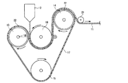
本発明の樹脂シートを製造するための製造装置の一例を図1に示す。
図1に示す製造装置は、押出機のTダイ12、第1冷却ロール13、第2冷却ロール14、第3冷却ロール15、第4冷却ロール16、金属製エンドレスベルト17、剥離ロール21を備える。
このように構成された製造装置を用いた急冷による樹脂シート11の製造方法の一例を以下に説明する。
Examples of the method for forming the resin sheet of the present invention include an extrusion method.
An example of the manufacturing apparatus for manufacturing the resin sheet of this invention is shown in FIG.
The manufacturing apparatus shown in FIG. 1 includes a T die 12 of an extruder, a
An example of a method for manufacturing the
まず、押し出された溶融樹脂と直接接触し、これを冷却する金属製エンドレスベルト17及び第4冷却ロール16の表面温度が露点以上、50℃以下、好ましくは30℃以下に保たれるように、予め各冷却ロール13、14、15、16の温度制御を行う。
First, the surface temperature of the metal
ここで、第4冷却ロール16及び金属製エンドレスベルト17の表面温度が露点以下では、表面に結露が生じ均一な製膜が困難になる可能性がある。一方、表面温度が50℃より高いと、得られるシート11の透明性が低くなるとともに、α晶が多くなり、熱成形しにくいものとなる可能性がある。従って、表面温度は例えば20℃である。
Here, if the surface temperature of the
次に、押出機のTダイ12より押し出された溶融樹脂(造核剤を含まない)を第1冷却ロール13上で金属製エンドレスベルト17と、第4冷却ロール16との間に挟み込む。この状態で、溶融樹脂を第1、第4冷却ロール13、16で圧接するとともに、20℃で急冷する。
この際、第1冷却ロール13及び第4冷却ロール16間の押圧力で弾性材22が圧縮されて弾性変形する。
この弾性材22が弾性変形している部分、即ち、第1冷却ロール13の中心角度θ1に対応する円弧部分で、急冷されたシートは各冷却ロール13、16により面状圧接されている。この際の面圧は、通常0.1MPa以上20MPa以下である。
Next, the molten resin (excluding the nucleating agent) extruded from the T die 12 of the extruder is sandwiched between the metal
At this time, the
The rapidly cooled sheet is press-contacted by the cooling rolls 13 and 16 at the portion where the
上述のように圧接され、第4冷却ロール16及び金属製エンドレスベルト17間に挟まれたシートは、続いて、第4冷却ロール16の略下半周に対応する円弧部分で金属製エンドレスベルト17と第4冷却ロール16とに挟まれて面状圧接される。この際の面圧は、通常0.01MPa以上0.5MPa以下である。
The sheet press-contacted as described above and sandwiched between the
このように第4冷却ロール16で面状圧接及び冷却された後、金属製エンドレスベルト17に密着したシートは、金属製エンドレスベルト17の回動とともに第2冷却ロール14上に移動される。ここで、剥離ロール21によりガイドされて第2冷却ロール14側に押圧されたシートは、前述同様、第2冷却ロール14の略上半周に対応する円弧部分で金属製エンドレスベルト17により面状圧接され、再び30℃以下の温度で冷却される。この際の面圧は、通常0.01MPa以上0.5MPa以下である。
After the sheet pressure contact and cooling by the
第2冷却ロール14上で冷却されたシートは、剥離ロール21により金属製エンドレスベルト17から剥離され、巻き取りロール(図示省略)により、所定の速度で巻き取られる。
The sheet cooled on the
[積層体]
本発明の積層体は、本発明の樹脂シートからなる第1の樹脂層、及び第2の樹脂層を含む。
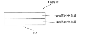
本発明の積層体を図2に示す。積層体1は、第1の樹脂層100及び第2の樹脂層200の積層構造であり、第1の樹脂層100の、第2の樹脂層200と反対側の面Aが、上記の各樹脂シートの特定の性質を有する。
本発明の積層体は、具体的には下記の第1〜第2の積層体である。
[Laminate]
The laminate of the present invention includes a first resin layer and a second resin layer made of the resin sheet of the present invention.
The laminate of the present invention is shown in FIG. The laminate 1 has a laminated structure of a first resin layer 100 and a second resin layer 200, and the surface A of the first resin layer 100 on the side opposite to the second resin layer 200 is the above-described resin. Have specific properties of the sheet.
The laminate of the present invention is specifically the following first to second laminates.
本発明の第1の積層体は、上記の第1の樹脂シートからなる第1の樹脂層、及び第2の樹脂層からなる。第1の樹脂層の、第2の樹脂層と反対側の面(面A)の算術平均粗さRaは0.15μm以下である。
第1の樹脂シート及び算術平均粗さRaは上述した通りである。
The 1st laminated body of this invention consists of the 1st resin layer which consists of said 1st resin sheet, and a 2nd resin layer. The arithmetic average roughness Ra of the surface (surface A) opposite to the second resin layer of the first resin layer is 0.15 μm or less.
The first resin sheet and the arithmetic average roughness Ra are as described above.
第2の樹脂層は、好ましくはポリオレフィンを含む。ポリオレフィンは第1の樹脂シートで説明した通りである。ポリオレフィンは、好ましくはポリプロピレン、ポリエチレン、又はポリプロピレン及びポリエチレンである。 The second resin layer preferably contains polyolefin. The polyolefin is as described in the first resin sheet. The polyolefin is preferably polypropylene, polyethylene, or polypropylene and polyethylene.
本発明の第2の積層体は、上記の第2の樹脂シートからなる第1の樹脂層、及び第2の樹脂層を含む。第1の樹脂層の、第2の樹脂層と反対側の面(面A)の静摩擦係数が0.5以下である。
第2の樹脂シート及び静摩擦係数は上述した通りである。
第2の樹脂層は第1の積層体における第2の樹脂層と同じである。
The 2nd laminated body of this invention contains the 1st resin layer which consists of said 2nd resin sheet, and a 2nd resin layer. The static friction coefficient of the surface (surface A) opposite to the second resin layer of the first resin layer is 0.5 or less.
The second resin sheet and the static friction coefficient are as described above.
The second resin layer is the same as the second resin layer in the first laminate.
本発明の積層体は、好ましくは、第1の樹脂層の、第2の樹脂層と反対側の面(面A)の動摩擦係数が0.5以下である。動摩擦係数は上述した通りである。 In the laminate of the present invention, the coefficient of dynamic friction of the surface (surface A) on the side opposite to the second resin layer of the first resin layer is preferably 0.5 or less. The dynamic friction coefficient is as described above.
本発明の積層体において、第1の樹脂層の厚さは、通常5〜200μmであり、好ましくは10〜100μmである。第2の樹脂層の厚さは、通常45〜800μmであり、好ましくは90〜400μmである。 In the laminate of the present invention, the thickness of the first resin layer is usually 5 to 200 μm, preferably 10 to 100 μm. The thickness of the second resin layer is usually 45 to 800 μm, preferably 90 to 400 μm.
(第3の樹脂層)
本発明の積層体は、第2の樹脂層の、第1の樹脂層と反対側の面に第3の樹脂層を含んでもよい。この場合、積層体は(第1の樹脂層/第2の樹脂層/第3の樹脂層)の構成となる。「/」は積層構造であることを示す。
(Third resin layer)
The laminate of the present invention may include a third resin layer on the surface of the second resin layer opposite to the first resin layer. In this case, the laminate has a configuration of (first resin layer / second resin layer / third resin layer). “/” Indicates a laminated structure.
第3の樹脂層は、例えばウレタン樹脂、アクリル樹脂、ポリオレフィン及びポリエステルから選択される1以上の樹脂を含む。第2の樹脂層やインキへの密着性や成形性を考慮すると、ウレタン樹脂が好ましい。 The third resin layer includes one or more resins selected from, for example, urethane resin, acrylic resin, polyolefin, and polyester. In consideration of adhesion to the second resin layer and ink and moldability, urethane resin is preferable.
ウレタン系樹脂は、ジイソシアネート、高分子量ポリオール及び鎖延長剤の反応物が好ましい。高分子量ポリオールとしては、ポリエーテルポリオール、ポリカーボネートポリオール等が挙げられる。
これにより、積層体を複雑な非平面状に成形しても、第1の層に第3の層が追従して良好に層構成を形成できる。また、後述する金属層のひび割れや剥離を防ぐことができる。
The urethane resin is preferably a reaction product of diisocyanate, high molecular weight polyol and chain extender. Examples of the high molecular weight polyol include polyether polyol and polycarbonate polyol.
Thereby, even if a laminated body is shape | molded in complicated non-planar shape, a 3rd layer follows a 1st layer and can form a favorable layer structure. Moreover, the crack and peeling of the metal layer mentioned later can be prevented.
第3の樹脂層は、ガラス転移温度が−50℃以上100℃以下であることが好ましい。ガラス転移温度が−50℃未満では、第3の樹脂層の歪みが後述する金属層や印刷層の追従性を超えるため、長期使用時に微細なクラックによる不良が発生するおそれがある。ガラス転移温度が100℃を超えると、軟化温度が高くなるため、予備附形時の伸びが悪くなり、延伸部の伸びムラが発生して、金属薄膜の微細割れが発生するおそれがある。
ガラス転移温度はJIS K7121に準拠した方法で測定できる。
The third resin layer preferably has a glass transition temperature of −50 ° C. or higher and 100 ° C. or lower. When the glass transition temperature is less than −50 ° C., the distortion of the third resin layer exceeds the followability of the metal layer and the printing layer described later, and thus there is a possibility that defects due to fine cracks may occur during long-term use. When the glass transition temperature exceeds 100 ° C., the softening temperature becomes high, so that the elongation at the time of preliminary shaping is deteriorated, the elongation unevenness of the stretched portion is generated, and there is a possibility that the metal thin film is finely cracked.
The glass transition temperature can be measured by a method based on JIS K7121.
第3の樹脂層は、引張破断伸度が好ましくは150%以上900%以下であり、より好ましくは200%以上850%以下であり、さらに好ましくは300%750%以下である。引張破断伸度が150%より低いと、熱成形時に第1の樹脂層の伸びに第2の樹脂層が追従することができずクラックが入り、後述する金属層や印刷層にひび割れが生じたり、剥離したりするおそれがある。引張破断伸度が900%を超えると耐水性が悪化するおそれがある。
引張破断伸度は、JIS K7311に準拠した方法で、厚み150μmの試料にて測定する。
The third resin layer preferably has a tensile elongation at break of 150% to 900%, more preferably 200% to 850%, and even more preferably 300% to 750%. If the tensile elongation at break is lower than 150%, the second resin layer cannot follow the elongation of the first resin layer at the time of thermoforming, and cracks may occur, resulting in cracks in the metal layer and print layer described later. There is a risk of peeling. If the tensile elongation at break exceeds 900%, the water resistance may deteriorate.
The tensile elongation at break is measured with a sample having a thickness of 150 μm by a method based on JIS K7311.
第3の樹脂層の軟化温度は、好ましくは50℃以上180℃以下であり、好ましくは90℃以上170℃以下であり、さらに好ましくは100℃以上165℃以下である。軟化温度が50℃より低いと、常温で第3の樹脂層の強度が不足し、金属又は金属酸化物からなる層や印刷層にひび割れが生じたり剥離したりするおそれがある。軟化温度が180℃より大きいと、熱成形時に十分軟化しきれず、第3の樹脂層にクラックが入り、後述する金属層や印刷層にひび割れが生じたり剥離したりするおそれがある。
軟化温度は高化式フローテスターによる流動開始温度を測定することにより測定する。
The softening temperature of the third resin layer is preferably 50 ° C. or higher and 180 ° C. or lower, preferably 90 ° C. or higher and 170 ° C. or lower, more preferably 100 ° C. or higher and 165 ° C. or lower. When the softening temperature is lower than 50 ° C., the strength of the third resin layer is insufficient at room temperature, and there is a possibility that the layer made of metal or metal oxide or the printed layer may crack or peel off. When the softening temperature is higher than 180 ° C., the softening cannot be sufficiently performed at the time of thermoforming, and the third resin layer is cracked, and there is a possibility that a metal layer and a printing layer described later are cracked or peeled off.
The softening temperature is measured by measuring the flow start temperature with a Koka flow tester.
第3の樹脂層の厚さは、0.01μm以上3μm以下が好ましく、より好ましくは0.03μm以上0.5μm以下である。第3の層の厚さが0.01μmより薄い場合、十分なインキ密着性を得ることができないおそれがある。一方、3μmより厚い場合、べた付きが生じてブロッキングの原因となるおそれがある。 The thickness of the third resin layer is preferably 0.01 μm or more and 3 μm or less, more preferably 0.03 μm or more and 0.5 μm or less. When the thickness of the third layer is less than 0.01 μm, there is a possibility that sufficient ink adhesion cannot be obtained. On the other hand, if it is thicker than 3 μm, stickiness may occur and cause blocking.
第3の樹脂層は、例えば、グラビアコーター、キスコーター、バーコーター等によって樹脂を塗布し、乾燥(例えば80℃にて1分間)することで、形成することができる。 The third resin layer can be formed by, for example, applying a resin with a gravure coater, kiss coater, bar coater or the like and drying (for example, at 80 ° C. for 1 minute).
(印刷層)
本発明の積層体は、第3の樹脂層の、第2の樹脂層と反対側の面に印刷層を含んでもよい。この場合、積層体は(第1の樹脂層/第2の樹脂層/第3の樹脂層/印刷層)の構成となる。
印刷層は、第3の樹脂層の一部に形成されてもよく、全面に形成されてもよい。印刷層の形状としては、特に制限されないが、例えばベタ状、カーボン調、木目調等の様々な形状が挙げられる。
(Print layer)
The laminate of the present invention may include a printed layer on the surface of the third resin layer opposite to the second resin layer. In this case, the laminate has a configuration of (first resin layer / second resin layer / third resin layer / printing layer).
The print layer may be formed on a part of the third resin layer or may be formed on the entire surface. The shape of the print layer is not particularly limited, and examples thereof include various shapes such as a solid shape, a carbon tone, and a woodgrain tone.
印刷の方法としては、スクリーン印刷法、オフセット印刷法、グラビア印刷法、ロールコート法、スプレーコート法等の一般的な印刷方法が利用できる。特に、スクリーン印刷法はインキの膜厚が厚くできるので、複雑な形状に成形した際にインキ割れが発生しにくいことから好ましい。
例えば、スクリーン印刷の場合、成形時の伸びに優れたインキが好ましく、十条ケミカル株式会社製の「FM3107高濃度白」や「SIM3207高濃度白」等が例示できるが、この限りではない。
As a printing method, a general printing method such as a screen printing method, an offset printing method, a gravure printing method, a roll coating method, or a spray coating method can be used. In particular, the screen printing method is preferable because the ink film thickness can be increased, and therefore, ink cracking hardly occurs when the ink is formed into a complicated shape.
For example, in the case of screen printing, an ink excellent in elongation at the time of molding is preferable, and examples thereof include “FM3107 high density white” and “SIM3207 high density white” manufactured by Jujo Chemical Co., Ltd., but are not limited thereto.
(金属層)
本発明の積層体は、第3の樹脂層の、第2の樹脂層と反対側の面に金属又は金属酸化物からなる金属層を含んでもよい。この場合、積層体は(第1の樹脂層/第2の樹脂層/第3の樹脂層/金属層)の構成となる。
(Metal layer)
The laminate of the present invention may include a metal layer made of a metal or a metal oxide on the surface of the third resin layer opposite to the second resin layer. In this case, the laminate has a configuration of (first resin layer / second resin layer / third resin layer / metal layer).
金属層において、金属又は金属酸化物の金属としては、積層体に金属調の意匠を付与できる金属であれば特に限定されないが、例えば、スズ、インジウム、クロム、アルミニウム、ニッケル、銅、銀、金、白金、亜鉛、及びこれらのうち少なくとも1種を含む合金等が挙げられる。これらの金属及びその酸化物は、1種単独でも、2種以上を組み合わせてもよい。
これらの中でも、伸展性の観点と、色調が優れるという観点から、好ましくはインジウム及びアルミニウムが挙げられる。これにより、積層体を三次元成形した際にクラックが発生しにくくなる。
In the metal layer, the metal or metal oxide is not particularly limited as long as it is a metal that can impart a metallic design to the laminate, but for example, tin, indium, chromium, aluminum, nickel, copper, silver, gold , Platinum, zinc, and alloys containing at least one of these. These metals and oxides thereof may be used alone or in combination of two or more.
Among these, indium and aluminum are preferable from the viewpoint of extensibility and excellent color tone. This makes it difficult for cracks to occur when the laminate is three-dimensionally formed.
また、当該金属層の上面の一部又は全面に印刷層を有してもよい。この場合、積層体は(第1の樹脂層/第2の樹脂層/第3の樹脂層/金属層/印刷層)の構成となる。印刷層は上述した通りである。 Moreover, you may have a printing layer in a part or whole surface of the upper surface of the said metal layer. In this case, the laminate has a configuration of (first resin layer / second resin layer / third resin layer / metal layer / printing layer). The print layer is as described above.
金属層の厚みは、5nm以上80nm以下が好ましく、15nm以上70nm以下が好ましい。5nm未満の場合、所望していた金属光沢が得られなくなるおそれがあり、一方、80nmを超えると、クラックが生じるおそれがある。 The thickness of the metal layer is preferably 5 nm to 80 nm, and more preferably 15 nm to 70 nm. If it is less than 5 nm, the desired metallic luster may not be obtained, while if it exceeds 80 nm, cracks may occur.
金属層の形成方法は、特に制限されないが、質感が高く高級感のある金属調の意匠を積層体に付与する観点から、例えば、上述の金属を用いた、蒸着法、真空蒸着法、スパッタリング法、イオンプレーティング法等が好ましい。特に、真空蒸着法は、低コストで、被蒸着体へのダメージが少ないため、好ましい。蒸着の条件は、用いる金属の溶融温度又は蒸発温度に応じて適宜設定すればよい。また、上記の金属を含むペーストを塗工する方法、上記の金属を用いためっき法等を用いることができる。 The method for forming the metal layer is not particularly limited, but from the viewpoint of imparting a high-quality and high-quality metallic design to the laminate, for example, a vapor deposition method, a vacuum vapor deposition method, or a sputtering method using the above-described metal. An ion plating method or the like is preferable. In particular, the vacuum evaporation method is preferable because it is low cost and causes little damage to the object to be evaporated. The conditions for the vapor deposition may be appropriately set according to the melting temperature or the evaporation temperature of the metal to be used. Moreover, the method of coating the paste containing said metal, the plating method using said metal, etc. can be used.
第3の樹脂層を設けずに印刷層を設けてもよく、この場合、第2の樹脂層の、前記第1の樹脂層と反対側の面の一部又は全面に印刷層を含む。この場合、積層体は(第1の樹脂層/第2の樹脂層/印刷層)の構成となる。印刷層は上述した通りである。
また、当該構成において、印刷層の上に金属層を設けてもよい。この場合、積層体は(第1の樹脂層/第2の樹脂層/印刷層/金属層)の構成となる。金属層は上述した通りである。
A printing layer may be provided without providing the third resin layer. In this case, a printing layer is included on a part or the entire surface of the second resin layer on the side opposite to the first resin layer. In this case, the laminate has a configuration of (first resin layer / second resin layer / printing layer). The print layer is as described above.
In the structure, a metal layer may be provided on the print layer. In this case, the laminate has a configuration of (first resin layer / second resin layer / printing layer / metal layer). The metal layer is as described above.
第3の樹脂層を設けずに金属層を設けてもよく、この場合、第2の樹脂層の、前記第1の樹脂層と反対側の面に金属層を含む。この場合、積層体は(第1の樹脂層/第2の樹脂層/金属層)の構成となる。金属層は上述した通りである。
また、当該構成において、金属層の上面の一部又は全面に印刷層を設けてもよい。この場合、積層体は(第1の樹脂層/第2の樹脂層/金属層/印刷層)の構成となる。印刷層は上述した通りである。
A metal layer may be provided without providing the third resin layer. In this case, a metal layer is included on the surface of the second resin layer on the side opposite to the first resin layer. In this case, the laminate has a configuration of (first resin layer / second resin layer / metal layer). The metal layer is as described above.
In the structure, a printed layer may be provided on a part or the entire upper surface of the metal layer. In this case, the laminate has a configuration of (first resin layer / second resin layer / metal layer / printing layer). The print layer is as described above.
本発明の積層体は、本発明の樹脂シートと同様の方法によって製造することができる。 The laminated body of this invention can be manufactured by the method similar to the resin sheet of this invention.
[成形体]
本発明の積層体を用いて成形体を作製することができる。
本発明の成形体は、第1の樹脂層からなる面の算術平均粗さRaが0.15μm以下であるか、及び/又は静摩擦係数が0.5以下である。
本発明の成形体は、好ましくは第1の樹脂層からなる面の動摩擦係数が0.5以下である。これらの性質は、上述した通りである。
[Molded body]
A molded body can be produced using the laminate of the present invention.
In the molded article of the present invention, the arithmetic average roughness Ra of the surface comprising the first resin layer is 0.15 μm or less and / or the static friction coefficient is 0.5 or less.
In the molded article of the present invention, the coefficient of dynamic friction of the surface made of the first resin layer is preferably 0.5 or less. These properties are as described above.
[成形体の製造方法]
成形体の成形方法としては、インモールド成形、インサート成形、被覆成形等が挙げられる。
[Method for producing molded article]
Examples of the molding method include in-mold molding, insert molding, and coating molding.
インモールド成形は、金型内に積層体を設置して、金型内に供給される成形用樹脂の圧力で所望の形状に成形して成形体を得る方法である。
インモールド成形として、積層体を金型に装着し、成形用樹脂を供給して一体化して行うことが好ましい。
In-mold molding is a method in which a laminate is placed in a mold and molded into a desired shape with the pressure of a molding resin supplied into the mold to obtain a molded body.
The in-mold molding is preferably performed by mounting the laminate on a mold and supplying and integrating a molding resin.
インサート成形では、金型内に設置する附形体を予備附形しておき、その形状に成形用樹脂を充填することで、成形体を得る方法である。より複雑な形状を出すことができる。
インサート成形として、積層体を金型に合致するよう附形し、附形した積層体を金型に装着し、成形用樹脂を供給して一体化して行うことが好ましい。
金型に合致するようする附形(予備附形)は、真空成型、圧空成型、真空圧空成型、プレス成型、プラグアシスト成形等で行うことが好ましい。
Insert molding is a method of obtaining a molded body by preliminarily shaping a shaped body to be installed in a mold and filling the shape with a molding resin. More complicated shapes can be produced.
The insert molding is preferably performed by forming the laminated body so as to match the mold, mounting the shaped laminated body on the mold, and supplying and integrating the molding resin.
The attachment (preliminary attachment) that matches the mold is preferably performed by vacuum forming, pressure forming, vacuum / pressure forming, press forming, plug assist forming, or the like.
成形用樹脂は、成形可能な熱可塑性樹脂が好ましい。具体的には、ポリプロピレン、ポリエチレン、ポリカーボネート、アセチレン−スチレン−ブタジエン共重合体、アクリル重合体等が例示できるが、この限りではない。ファイバーやタルク等の無機フィラーを添加してもよい。
供給は、射出で行うことが好ましく、圧力5MPa以上120MPa以下が好ましい。
金型温度は20℃以上90℃以下であることが好ましい。
The molding resin is preferably a moldable thermoplastic resin. Specific examples include polypropylene, polyethylene, polycarbonate, acetylene-styrene-butadiene copolymer, and acrylic polymer, but are not limited thereto. Inorganic fillers such as fiber and talc may be added.
The supply is preferably performed by injection, and the pressure is preferably 5 MPa or more and 120 MPa or less.
The mold temperature is preferably 20 ° C. or higher and 90 ° C. or lower.
被覆成形として、チャンバーボックス内に芯材を配設し、芯材の上方に、積層体を配置し、チャンバーボックス内を減圧し、積層体を加熱軟化し、芯材の上面に、積層体を接触し、加熱軟化させた積層体を芯材に押圧して被覆させることが好ましい。
加熱軟化後、芯材の上面に、積層体を接触させることが好ましい。
押圧は、チャンバーボックス内において、積層体の、芯材と接する側を減圧したまま、積層体の、芯材の反対側を加圧することが好ましい。
As covering molding, a core material is arranged in a chamber box, a laminate is arranged above the core material, the inside of the chamber box is decompressed, the laminate is heated and softened, and the laminate is placed on the upper surface of the core material. It is preferable that the laminated body that has been brought into contact and softened by heating is pressed against the core material to be coated.
After heat softening, it is preferable to bring the laminate into contact with the upper surface of the core material.
In the pressing, it is preferable to pressurize the opposite side of the core of the laminate while reducing the pressure of the side of the laminate that contacts the core in the chamber box.
芯材は、凸状でも凹状であってもよく、例えば三次元曲面を有する樹脂、金属、セラミック等が挙げられる。樹脂は、上述の成形に用いる樹脂と同様のものが挙げられる。 The core material may be convex or concave, and examples thereof include a resin having a three-dimensional curved surface, metal, and ceramic. Examples of the resin include the same resins as those used for the molding described above.
具体的には、互いに分離可能な、上下ふたつの成型室から構成されるチャンバーボックスを用いることが好ましい。
まず、下成型室内のテーブル上へ芯材を載せ、セットする。被成型物である本発明の積層体を下成型室上面にクランプで固定する。この際、上・下成型室内は大気圧である。
次に上成型室を降下させ、上・下成型室を接合させ、チャンバーボックス内を閉塞状態にする。上・下成型室内の両方を大気圧状態から、真空タンクによって真空吸引状態とする。
上・下成型室内を真空吸引状態にした後、ヒータを点けて加飾シートの加熱を行なう。次に上・下成型室内は真空状態のまま下成型室内のテーブルを上昇させる。
次に、上成型室内の真空を開放し大気圧を入れることによって、被成型物である本発明の積層体は芯材へ押し付けられてオーバーレイ(成型)される。尚、上成型室内に圧縮空気を供給することで、より大きな力で被成型物である本発明の積層体を芯材へ密着させることも可能である。
オーバーレイが完了した後、ヒータを消灯し、下成型室内の真空も開放して大気圧状態へ戻し、上成型室を上昇させ、加飾印刷された積層体が表皮材として被覆された製品を取り出す。
Specifically, it is preferable to use a chamber box composed of two upper and lower molding chambers that can be separated from each other.
First, a core material is placed and set on a table in the lower molding chamber. The laminate of the present invention, which is a molding object, is fixed to the upper surface of the lower molding chamber with a clamp. At this time, the upper and lower molding chambers are at atmospheric pressure.
Next, the upper molding chamber is lowered, the upper and lower molding chambers are joined, and the inside of the chamber box is closed. Both the upper and lower molding chambers are brought into the vacuum suction state from the atmospheric pressure state by the vacuum tank.
After the upper and lower molding chambers are evacuated, the heater is turned on and the decorative sheet is heated. Next, the table in the lower molding chamber is raised while the upper and lower molding chambers are in a vacuum state.
Next, by releasing the vacuum in the upper molding chamber and applying atmospheric pressure, the laminate of the present invention, which is a molding object, is pressed against the core material and overlaid (molded). In addition, by supplying compressed air into the upper molding chamber, the laminate of the present invention, which is a molding object, can be brought into close contact with the core material with a greater force.
After the overlay is completed, the heater is turned off, the vacuum in the lower molding chamber is released to return to atmospheric pressure, the upper molding chamber is raised, and the product with the decorative printed laminate coated as the skin material is taken out. .
[成形体等の用途]
本発明の積層体及び成形体は、鞍乗型車両の外装部品又は四輪車の外装部品として好適に用いることができる。
雨天や未舗装路の走行時に、自車の車輪や他車が巻き上げた泥が外装部品に、汚れとなって付着する。また、水分を含んでぬかるんだ未舗装路では、外装部品に泥が蓄積し、車両重量が重くなる。本発明の積層体及び成形体(例えばマッドカバー)は、最表面にシリコーン−オレフィン共重合体を含み表面エネルギーが小さいため、泥が付着しても密着しない。さらに、表面が平滑であるため成形品と泥の接触面積が小さく、走行時の振動により容易に泥が滑り成形体から脱落する。泥が蓄積しなくなるため、質量増加による走行性能の低下を防止することができる。
[Uses for molded products]
The laminate and molded body of the present invention can be suitably used as an exterior part for a saddle-ride type vehicle or an exterior part for a four-wheeled vehicle.
When running on rainy or unpaved roads, mud rolled up by the vehicle's wheels and other vehicles becomes dirty and adheres to the exterior parts. On an unpaved road that contains moisture, mud accumulates on the exterior parts, increasing the vehicle weight. Since the laminate and molded body (for example, mud cover) of the present invention contain a silicone-olefin copolymer on the outermost surface and have a small surface energy, they do not adhere even if mud adheres. Furthermore, since the surface is smooth, the contact area between the molded product and the mud is small, and mud easily falls off the sliding molded body due to vibration during traveling. Since mud does not accumulate, it is possible to prevent a decrease in running performance due to an increase in mass.
本発明の積層体及び成形体は、鞍乗型車両と四輪車の外装部品以外にも、車両の内装材、家電の筐体、化粧鋼鈑、化粧板、住宅設備、情報通信機器の筐体等、汚れが付着する可能性がある部品に好適である。 The laminated body and molded body of the present invention, in addition to exterior components for saddle riding type vehicles and four-wheeled vehicles, include vehicle interior materials, housings for home appliances, decorative steel plates, decorative plates, housing equipment, and housings for information and communication devices. It is suitable for parts such as the body where dirt may adhere.
実施例1
[積層体の製造]
図1に示す製造装置を用い、以下のようにして第1の樹脂層と第2の樹脂層からなる積層体を製造した。
ポリオレフィン(商品名:プライムポリプロF−133A、株式会社プライムポリマー製(メルトフローインデックス3g/10min、ホモポリプロピレン))(95質量%)、及びシリコーン−オレフィン共重合体(商品名:イクスフォーラ、三井化学株式会社製)(5質量%)を第1の樹脂層用の押出機(図示せず)に投入した。
ポリオレフィン(商品名:プライムポリプロF−133A、株式会社プライムポリマー製(メルトフローインデックス3g/10min、ホモポリプロピレン))を第2の樹脂層用の押出機(図示せず)に投入した。
Example 1
[Manufacture of laminates]
Using the manufacturing apparatus shown in FIG. 1, a laminate composed of the first resin layer and the second resin layer was manufactured as follows.
Polyolefin (trade name: Prime Polypro F-133A, manufactured by Prime Polymer Co., Ltd. (melt flow index 3 g / 10 min, homopolypropylene)) (95% by mass), and silicone-olefin copolymer (trade name: EXFORA, Mitsui Chemicals) (Made by Co., Ltd.) (5% by mass) was charged into an extruder (not shown) for the first resin layer.
Polyolefin (trade name: Prime Polypro F-133A, manufactured by Prime Polymer Co., Ltd. (melt flow index 3 g / 10 min, homopolypropylene)) was charged into an extruder (not shown) for the second resin layer.
混練しながら、以下の条件で押し出して積層体を得た。
第1の樹脂層用の押出機の直径:65mm
第2の樹脂層用の押出機の直径:75mm
Tダイの幅:900mm
積層シートの引取速度:6m/分
冷却ロール及び金属製エンドレスベルトの表面温度:20℃
冷却ロールの算術平均粗さRa:0.032μm
冷却速度:10,800℃/分
第1の樹脂層の厚さ:50μm
第2の樹脂層の厚さ:150μm
While kneading, extrusion was performed under the following conditions to obtain a laminate.
Diameter of extruder for first resin layer: 65 mm
Diameter of extruder for second resin layer: 75 mm
T die width: 900mm
Take-up speed of laminated sheet: 6 m / min Surface temperature of cooling roll and metal endless belt: 20 ° C
Arithmetic average roughness Ra of the cooling roll: 0.032 μm
Cooling rate: 10,800 ° C./min. First resin layer thickness: 50 μm
Second resin layer thickness: 150 μm
[算術平均粗さRaの測定]
得られた積層体における第1の樹脂層からなる面について、算術平均粗さRaを以下の測定装置と測定条件で測定した。
・測定装置:オリンパス株式会社製 3D測定レーザー顕微鏡(LEXT4000LS)
・測定条件
対物レンズ:20倍
ズーム:1倍
測定ピッチ:0.06μm
測定 操作モード:X,Y,Z高精度カラー
測定エリア:面
測定品質:高精度
解析長さ:642μm
[Measurement of arithmetic average roughness Ra]
About the surface which consists of a 1st resin layer in the obtained laminated body, arithmetic mean roughness Ra was measured with the following measuring devices and measurement conditions.
Measurement device: Olympus 3D measurement laser microscope (EXT4000LS)
Measurement conditions Objective lens: 20 × zoom: 1 × measurement pitch: 0.06 μm
Measurement Operation mode: X, Y, Z high-precision color measurement area: Surface measurement quality: High-precision analysis length: 642 μm
[静摩擦係数・動摩擦係数の測定]
得られた積層体における第1の樹脂層からなる面について、静摩擦係数と動摩擦係数を以下の測定装置、測定条件、算出方法で測定した。
・測定装置:株式会社島津製作所製 オートグラフAGSX−1kN
・測定条件
移動側試験片の形状:80mm(流れ方向)×70mm(幅方向)
固定側試験片の形状:170mm(流れ方向)×110mm(幅方向)
移動動錘の質量:324.6g
クロスヘッドスピード:300mm/分
移動距離:50mm
・静摩擦係数の算出方法
静摩擦係数は、最初のピーク点の試験力と移動動錘の質量を用いて、以下の式から算出した。
静摩擦係数=ピーク点の試験力/移動動錘の質量
・動摩擦係数の算出方法
動摩擦係数は、ストロークが10mmから40mmの間の試験力平均と移動動錘の質量を用いて、以下の式から算出した。
動摩擦係数=ストローク10mm〜40mmの平均試験力/移動動錘の質量
[Measurement of static friction coefficient and dynamic friction coefficient]
About the surface which consists of a 1st resin layer in the obtained laminated body, the static friction coefficient and the dynamic friction coefficient were measured with the following measuring apparatuses, measurement conditions, and the calculation method.
-Measuring device: Autograph AGSX-1kN manufactured by Shimadzu Corporation
-Measurement condition Shape of moving side test piece: 80 mm (flow direction) x 70 mm (width direction)
Fixed-side specimen shape: 170 mm (flow direction) x 110 mm (width direction)
Mass of moving weight: 324.6g
Crosshead speed: 300 mm / min Travel distance: 50 mm
-Static friction coefficient calculation method The static friction coefficient was calculated from the following equation using the test force at the first peak point and the mass of the moving moving weight.
Static friction coefficient = Peak point test force / Movement weight mass and dynamic friction coefficient calculation method The dynamic friction coefficient is calculated from the following equation using the average test force between the strokes of 10mm and 40mm and the mass of the movement weight. did.
Coefficient of dynamic friction = average test force with a stroke of 10 mm to 40 mm / mass of moving weight
[泥付着特性の評価]
得られた積層体を、厚さ2mm、短辺65mm、長辺150mmの平板状の金型に装着し、油圧式射出成形機IS−80EPN(東芝機械株式会社製)にて、プライムポリプロJ−705UG(株式会社プライムポリマー製、メルトフローインデックス9g/10min、ブロックポリプロピレン)を金型内に供給して一体化させ、泥付着特性評価用の成形体を作製した。
[Evaluation of mud adhesion characteristics]
The obtained laminate was mounted on a flat plate mold having a thickness of 2 mm, a short side of 65 mm, and a long side of 150 mm, and primed polypro J- using a hydraulic injection molding machine IS-80EPN (manufactured by Toshiba Machine Co., Ltd.). 705UG (manufactured by Prime Polymer Co., Ltd., melt flow index 9 g / 10 min, block polypropylene) was supplied into the mold and integrated to produce a molded body for evaluating mud adhesion characteristics.
黄色土を60℃で4時間乾燥して水分を抜き、これにイオン交換水を35質量%となるように混合し、泥付着特性評価用の泥とした。 The yellow soil was dried at 60 ° C. for 4 hours to remove moisture, and ion exchange water was mixed with this to 35% by mass to obtain mud for evaluating mud adhesion characteristics.
泥付着特性評価用の泥20gを、泥付着特性評価用の成形体の第1の樹脂層の上に置き、当該成形体を地面から40°傾けて泥を滑らせた。下記基準に基づいて泥付着特性を評価した。結果を表1に示す。
○:泥が全量滑り落ちる
△:泥が滑り落ちるも、滑った後に微量の泥が付着している
×:泥が滑らない、又は滑った後に泥が多く付着している
20 g of mud for evaluating mud adhesion characteristics was placed on the first resin layer of the molded body for evaluating mud adhesion characteristics, and the molded body was tilted 40 ° from the ground to slide mud. The mud adhesion characteristics were evaluated based on the following criteria. The results are shown in Table 1.
○: Mud slides down △: Mud slides, but a small amount of mud adheres after sliding ×: Mud does not slip, or much mud adheres after sliding
実施例2
製造装置の冷却ロール表面の算術平均粗さRaを0.02μmに変更した以外は、実施例1と同様に積層体を製造し、評価した。結果を表1に示す。
Example 2
A laminate was produced and evaluated in the same manner as in Example 1 except that the arithmetic average roughness Ra of the cooling roll surface of the production apparatus was changed to 0.02 μm. The results are shown in Table 1.
比較例1
シリコーン−オレフィン共重合体を用いずに第1の樹脂層を形成した以外は、実施例1と同様に積層体を製造し、評価した。結果を表1に示す。
Comparative Example 1
A laminate was produced and evaluated in the same manner as in Example 1 except that the first resin layer was formed without using the silicone-olefin copolymer. The results are shown in Table 1.
比較例2
製造装置の冷却ロール表面の算術平均粗さRaを0.50μmに変更した以外は、実施例1と同様に積層体を製造し、評価した。結果を表1に示す。
Comparative Example 2
A laminate was produced and evaluated in the same manner as in Example 1 except that the arithmetic average roughness Ra of the surface of the cooling roll of the production apparatus was changed to 0.50 μm. The results are shown in Table 1.
表1より、特定の面特性を有する本発明の成形体(積層体)は、特定の面特性を有さない比較例2の成形体と比較して、優位な防泥性があることを確認した。
また、第1の樹脂層にシリコーン−オレフィン共重合体を有する本発明の成形体(積層体)は、第1の樹脂層にシリコーン−オレフィン共重合体を有しない比較例1の成形体と比較して、優位な防泥性があることを確認した。
From Table 1, it is confirmed that the molded product (laminate) of the present invention having specific surface characteristics has superior anti-slip properties compared to the molded product of Comparative Example 2 having no specific surface characteristics. did.
Further, the molded product (laminate) of the present invention having a silicone-olefin copolymer in the first resin layer is compared with the molded product of Comparative Example 1 having no silicone-olefin copolymer in the first resin layer. It was confirmed that there was an excellent mud-proof property.
1 積層体
11 シート
12 Tダイ
13 第1冷却ロール
14 第2冷却ロール
15 第3冷却ロール
16 第4冷却ロール
17 金属製エンドレスベルト
22 弾性材
100 第1の樹脂シート
200 第2の樹脂シート
DESCRIPTION OF SYMBOLS 1
Claims (26)
前記第1の樹脂層の、前記第2の樹脂層と反対側の面の算術平均粗さRaが0.15μm以下である積層体。 A laminate comprising a first resin layer comprising the resin sheet according to claim 1 and a second resin layer,
The laminated body whose arithmetic mean roughness Ra of the surface on the opposite side to the said 2nd resin layer of the said 1st resin layer is 0.15 micrometer or less.
前記第1の樹脂層の、前記第2の樹脂層と反対側の面の静摩擦係数が0.4以下である積層体。 A laminate comprising a first resin layer comprising the resin sheet according to claim 2 and a second resin layer,
The laminated body whose static friction coefficient of the surface on the opposite side to the said 2nd resin layer of the said 1st resin layer is 0.4 or less.
チャンバーボックス内に芯材を配設し、
前記芯材の上方に、前記積層体を配置し、
前記チャンバーボックス内を減圧し、
前記積層体を加熱軟化し、
加熱軟化させた前記積層体を前記芯材に押圧して被覆させる請求項21に記載の成形体の製造方法。 The molding,
A core material is arranged in the chamber box,
Arrange the laminated body above the core material,
Depressurizing the inside of the chamber box,
Heat softening the laminate,
The manufacturing method of the molded object of Claim 21 which presses and coat | covers the said laminated body heat-softened to the said core material.
Priority Applications (1)
| Application Number | Priority Date | Filing Date | Title |
|---|---|---|---|
| JP2016098253A JP2017206587A (en) | 2016-05-16 | 2016-05-16 | Resin sheet, laminate, molding, method for producing molding, vehicular exterior part and interior material fabricated with molding, and cabinet of household electrical appliance and the like |
Applications Claiming Priority (1)
| Application Number | Priority Date | Filing Date | Title |
|---|---|---|---|
| JP2016098253A JP2017206587A (en) | 2016-05-16 | 2016-05-16 | Resin sheet, laminate, molding, method for producing molding, vehicular exterior part and interior material fabricated with molding, and cabinet of household electrical appliance and the like |
Publications (1)
| Publication Number | Publication Date |
|---|---|
| JP2017206587A true JP2017206587A (en) | 2017-11-24 |
Family
ID=60416299
Family Applications (1)
| Application Number | Title | Priority Date | Filing Date |
|---|---|---|---|
| JP2016098253A Ceased JP2017206587A (en) | 2016-05-16 | 2016-05-16 | Resin sheet, laminate, molding, method for producing molding, vehicular exterior part and interior material fabricated with molding, and cabinet of household electrical appliance and the like |
Country Status (1)
| Country | Link |
|---|---|
| JP (1) | JP2017206587A (en) |
Cited By (1)
| Publication number | Priority date | Publication date | Assignee | Title |
|---|---|---|---|---|
| WO2022080084A1 (en) * | 2020-10-16 | 2022-04-21 | 出光ユニテック株式会社 | Resin sheet, laminate, molded body, and method for producing molded body |
-
2016
- 2016-05-16 JP JP2016098253A patent/JP2017206587A/en not_active Ceased
Cited By (1)
| Publication number | Priority date | Publication date | Assignee | Title |
|---|---|---|---|---|
| WO2022080084A1 (en) * | 2020-10-16 | 2022-04-21 | 出光ユニテック株式会社 | Resin sheet, laminate, molded body, and method for producing molded body |
Similar Documents
| Publication | Publication Date | Title |
|---|---|---|
| JP6917689B2 (en) | Decorative sheet and laminated sheet for decoration | |
| JP5393913B2 (en) | Decorative resin sheet, resin molded body, and method for producing the same | |
| JP2014198415A (en) | Composite molded article | |
| CN108495750B (en) | Laminate, molded body using laminate, and method for producing same | |
| JP5922506B2 (en) | Transparent resin film | |
| JP2001310427A (en) | Laminated film | |
| JPWO2019065912A1 (en) | Decorative molding of multilayer film and fiber reinforced plastic | |
| JP2017206587A (en) | Resin sheet, laminate, molding, method for producing molding, vehicular exterior part and interior material fabricated with molding, and cabinet of household electrical appliance and the like | |
| JP2012016951A (en) | Decorative sheet simultaneously formed with injection-molding and method for manufacturing the decorative sheet simultaneously formed with injection-molding | |
| JP2000038459A (en) | Film or sheet, laminated structure and its use | |
| JP6779095B2 (en) | Manufacturing method of shaping decorative sheet | |
| CN111971355B (en) | Multilayer film and molded body provided with same | |
| JP6963392B2 (en) | Laminated body, molded body and manufacturing method of molded body | |
| WO2018151090A1 (en) | Laminate, decorative sheet, method for producing laminate, method for producing molded body, and molded body | |
| JP2002067078A (en) | Method of manufacturing decorated molded article | |
| KR20180098353A (en) | Conjugates and methods for their preparation | |
| JP4383460B2 (en) | Manufacturing method of decorative molded products | |
| JP2014009316A (en) | Emboss decorative sheet and emboss decorative integrally-molded article | |
| JP2018039915A (en) | Decorative sheet and decorative laminated sheet | |
| JP6514473B2 (en) | LAMINATE, MOLDED BODY, MOLDED ARTICLE, AND METHOD FOR PRODUCING MOLDED ARTICLE | |
| JP2003136637A (en) | Decorative sheet and decorative molded product | |
| JP3979819B2 (en) | Manufacturing method of decorative molded products | |
| JP5015996B2 (en) | Sheet for simultaneous injection molding | |
| JP4498505B2 (en) | Sheet for simultaneous injection molding and method for producing the same | |
| JP2023067235A (en) | Resin sheet, laminate, molded article, and method for manufacturing molded article |
Legal Events
| Date | Code | Title | Description |
|---|---|---|---|
| A621 | Written request for application examination |
Free format text: JAPANESE INTERMEDIATE CODE: A621 Effective date: 20181206 |
|
| A131 | Notification of reasons for refusal |
Free format text: JAPANESE INTERMEDIATE CODE: A131 Effective date: 20191203 |
|
| A521 | Written amendment |
Free format text: JAPANESE INTERMEDIATE CODE: A523 Effective date: 20200203 |
|
| A01 | Written decision to grant a patent or to grant a registration (utility model) |
Free format text: JAPANESE INTERMEDIATE CODE: A01 Effective date: 20200630 |
|
| A045 | Written measure of dismissal of application |
Free format text: JAPANESE INTERMEDIATE CODE: A045 Effective date: 20201124 |