JP2017148860A - Press working device - Google Patents
Press working device Download PDFInfo
- Publication number
- JP2017148860A JP2017148860A JP2016036376A JP2016036376A JP2017148860A JP 2017148860 A JP2017148860 A JP 2017148860A JP 2016036376 A JP2016036376 A JP 2016036376A JP 2016036376 A JP2016036376 A JP 2016036376A JP 2017148860 A JP2017148860 A JP 2017148860A
- Authority
- JP
- Japan
- Prior art keywords
- hydraulic
- secondary processing
- press
- pressure
- workpiece
- Prior art date
- Legal status (The legal status is an assumption and is not a legal conclusion. Google has not performed a legal analysis and makes no representation as to the accuracy of the status listed.)
- Granted
Links
Images

Abstract
Description
本発明は、ワークのプレス成形と、該プレス成形に続く当該ワークの二次加工とを連続的に行なうプレス加工装置に関する。 The present invention relates to a press working apparatus that continuously performs press forming of a workpiece and secondary processing of the workpiece following the press forming.
特許文献1には、上型の下降によってパネルの曲げ加工を行ない、次いで、その曲げ加工されたフランジ部に穴抜きポンチによって打抜き加工を行なうプレス加工装置が記載されている。このプレス加工装置では、曲げ加工時のプレス機のラムの下降エネルギーで気体を圧縮してガス圧として蓄える蓄圧手段を備え、この蓄圧手段と穴抜きポンチ駆動用の推力発生手段(エアシリンダ)とを結ぶ接続通路に電磁弁が設けられている。打抜き加工時に上記電磁弁を開にすることにより、蓄圧手段から圧縮気体を推力発生手段に供給して、穴抜きポンチを駆動するようになっている。 Patent Document 1 describes a press working apparatus in which a panel is bent by lowering an upper die, and then a punching process is performed on the bent flange portion by a punching punch. This press working apparatus includes pressure accumulating means for compressing gas and storing it as gas pressure by the descending energy of the ram of the press machine during bending, and this pressure accumulating means and thrust generating means (air cylinder) for driving a punch punch A solenoid valve is provided in the connection passage connecting the two. By opening the solenoid valve at the time of punching, compressed gas is supplied from the pressure accumulating means to the thrust generating means, and the punching punch is driven.
特許文献2には、プレス加工装置において、パッドがワークに当接するときの衝突音を低減するために、パッドがワークに当接する直前にパッドを上型に対して相対的に上昇させる機構を設け、該機構に流量制御弁付の油圧アキュムレータを用いることが記載されている。当該機構は、上型の下降力によって作動油を吐出する第1油圧シリンダと、その作動油でパッドを上昇させる第2油圧シリンダとを備えている。この両油圧シリンダを結ぶ油路に流量制御弁付の油圧アキュムレータを設けることにより、第1油圧シリンダから第2油圧シリンダに送られる作動油量を制御するようにされている。
特許文献1に記載されたプレス加工装置によれば、曲げ加工時のラムの下降エネルギーの一部を蓄圧手段でガス圧として蓄え、これを打抜き加工に用いるから、エネルギーロスが少なくなる。 According to the press working apparatus described in Patent Document 1, a part of the descending energy of the ram at the time of bending is stored as a gas pressure by the pressure accumulating means, and this is used for punching work, so that energy loss is reduced.
しかし、蓄圧手段内の気体をラムの下降エネルギーで圧縮しても、蓄圧手段と穴抜きポンチ駆動用の推力発生手段を結ぶ接続通路の電磁弁から推力発生手段に至る間の気体は圧縮されない。従って、電磁弁を開にして、蓄圧手段の圧縮気体を推力発生手段に向けて開放しても、上記電磁弁から推力発生手段に至る接続通路の気体が圧縮状態になって穴抜きポンチが駆動されるまでには時間的遅れを生ずるとともに、穴抜きポンチの動作が不安定になりやすい。 However, even if the gas in the pressure accumulating means is compressed with the descending energy of the ram, the gas between the electromagnetic valve in the connecting passage connecting the pressure accumulating means and the thrust generating means for driving the punching punch to the thrust generating means is not compressed. Therefore, even if the solenoid valve is opened and the compressed gas of the pressure accumulating means is released toward the thrust generating means, the gas in the connection passage from the solenoid valve to the thrust generating means is compressed and the punching punch is driven. A time delay occurs until the punching is performed, and the operation of the punching punch tends to become unstable.
しかも、穴抜きポンチを駆動するには、上記電磁弁から推力発生手段に至る接続通路の気体を圧縮しなければならないから、蓄圧手段における気体の圧縮量を大きくする必要がある。すなわち、蓄圧手段の大型化が必要になる。特に、ワークの打ち抜き加工等の二次加工に多数の推力発生手段を用いる場合、接続通路の本数が多くなるから、蓄圧手段の大型化が顕著になり、二次加工具の動作も不安定になりやすい。 Moreover, in order to drive the hole punch, it is necessary to compress the gas in the connection passage from the solenoid valve to the thrust generating means, so it is necessary to increase the amount of gas compression in the pressure accumulating means. That is, it is necessary to increase the size of the pressure accumulating means. In particular, when a large number of thrust generating means are used for secondary processing such as workpiece punching, the number of connecting passages increases, so the pressure storage means becomes significantly larger and the operation of the secondary processing tool becomes unstable. Prone.
そこで、本発明は、ラムの下降エネルギーをワークの二次加工に用いるにあたり、プレス加工装置の大型化を抑えながら、二次加工具を応答性良く安定に動作させることを課題とする。 Accordingly, an object of the present invention is to stably operate a secondary processing tool with high responsiveness while suppressing an increase in the size of a press processing apparatus when the descending energy of a ram is used for secondary processing of a workpiece.
本発明は、上記課題を解決するために、二次加工具を、気体ではなく、作動液を媒体として駆動するようにし、その駆動のために、上記下降エネルギーによって液圧を発生させ、その液圧をガス圧に変換して蓄えるようにした。 In order to solve the above-mentioned problems, the present invention is configured such that the secondary processing tool is driven not by gas but by a working fluid as a medium, and for the driving, a hydraulic pressure is generated by the descending energy, and the liquid is Pressure was converted to gas pressure and stored.
ここに開示するプレス加工装置は、ワークのプレス成形と当該ワークの二次加工とを行なう装置であって、
プレス機のラムの下降によって上記ワークをプレス成形する上型及び下型と、
上記ワークの二次加工をする二次加工具と、
上記二次加工具を復帰させるリターンスプリングと、
作動液を媒体として上記二次加工具を駆動する液圧回路とを備え、
上記液圧回路は、
上記ラムの下降エネルギーによって上記作動液を吐出する液圧発生シリンダと、
上記液圧発生シリンダが発生する液圧をガス圧に変換して蓄えるアキュムレータと、
上記アキュムレータで蓄えられた液圧を利用して上記二次加工具を二次加工方向に駆動するアクチュエータと、
上記作動液の流路を、上記アキュムレータに液圧が蓄えられるように上記液圧発生シリンダから作動液を吐出させる流路と、上記アクチュエータが上記二次加工具を駆動するように上記アキュムレータから作動液を吐出させる流路と、上記リターンスプリングの付勢によって上記二次加工具が復帰するように上記アクチュエータから作動液を吐出させる流路とに切り換える切換手段とを備えていることを特徴とする。
The press working apparatus disclosed herein is an apparatus that performs press molding of a workpiece and secondary machining of the workpiece,
An upper die and a lower die for press-molding the workpiece by lowering the ram of the press machine;
A secondary processing tool for secondary processing of the workpiece;
A return spring for returning the secondary processing tool;
A hydraulic circuit that drives the secondary processing tool using hydraulic fluid as a medium;
The hydraulic circuit is
A hydraulic pressure generating cylinder that discharges the hydraulic fluid by lowering energy of the ram;
An accumulator that converts the hydraulic pressure generated by the hydraulic pressure generating cylinder into a gas pressure and stores it;
An actuator that drives the secondary processing tool in the secondary processing direction using the hydraulic pressure stored in the accumulator;
The hydraulic fluid passage is operated from the accumulator so that the hydraulic fluid is discharged from the hydraulic pressure generating cylinder so that the hydraulic pressure is stored in the accumulator, and the actuator drives the secondary processing tool. And a switching means for switching between a flow path for discharging the liquid and a flow path for discharging the hydraulic fluid from the actuator so that the secondary processing tool is restored by the urging of the return spring. .
このプレス加工装置では、ワークをプレス成形するときに、作動液の流路を液圧発生シリンダから作動液が吐出される流路にすると、液圧発生シリンダがラムの下降エネルギーによって作動液を吐出して液圧が発生し、その液圧がアキュムレータによってガス圧に変換されて蓄えられる。ワークの二次加工の際に、アキュムレータから作動液が吐出されるように流路を切り換えると、アキュムレータからアクチュエータに液圧が伝わり、二次加工具が二次加工方向に駆動される。二次加工後、アクチュエータから作動液が吐出されるように流路を切り換えると、二次加工具がリターンスプリングの付勢によって復帰する。 In this press working device, when press-molding a workpiece, if the flow path of hydraulic fluid is made to be a flow path from which hydraulic fluid is discharged from the hydraulic pressure generating cylinder, the hydraulic pressure generating cylinder discharges the hydraulic fluid by the lowering energy of the ram. Then, a hydraulic pressure is generated, and the hydraulic pressure is converted into a gas pressure by an accumulator and stored. When the flow path is switched so that the working fluid is discharged from the accumulator during the secondary processing of the workpiece, the hydraulic pressure is transmitted from the accumulator to the actuator, and the secondary processing tool is driven in the secondary processing direction. After the secondary processing, when the flow path is switched so that the working fluid is discharged from the actuator, the secondary processing tool is restored by the bias of the return spring.
ここに、二次加工具を駆動する液圧回路の作動液は実質的に非圧縮性の媒体であるから、アキュムレータとアクチュエータが離れていても、上記作動液の流路の切換によって、アキュムレータからアクチュエータに直ちに液圧が伝わり、二次加工具が応答性良く且つ安定して駆動されることになる。また、特許文献1とは違って、アキュムレータとアクチュエータを結ぶ流路に存する媒体を圧縮する必要がないから、つまり、アキュムレータは実際にアクチュエータに供給される量に対応する量の作動液を蓄えることで足りるから、アキュムレータの小型化に有利になる。特に、複数のアクチュエータを設ける場合において、アキュムレータの大型化を避けることができる。同じ理由から、液圧発生シリンダも、アクチュエータへの供給に必要な油量を吐出し得ることで足りるから、その小型化に有利になる。 Here, since the hydraulic fluid of the hydraulic circuit that drives the secondary processing tool is a substantially incompressible medium, even if the accumulator and the actuator are separated from each other, the accumulator is switched by switching the flow path of the hydraulic fluid. The hydraulic pressure is immediately transmitted to the actuator, and the secondary processing tool is driven with good responsiveness and stability. Further, unlike Patent Document 1, there is no need to compress the medium existing in the flow path connecting the accumulator and the actuator, that is, the accumulator stores the amount of hydraulic fluid corresponding to the amount actually supplied to the actuator. Therefore, it is advantageous for downsizing the accumulator. In particular, when a plurality of actuators are provided, it is possible to avoid an increase in the size of the accumulator. For the same reason, the hydraulic pressure generating cylinder is also advantageous in reducing its size because it is sufficient to discharge the amount of oil necessary for supply to the actuator.
本発明の好ましい態様では、上記上型及び下型は、加熱された上記ワークのプレス成形と、該プレス成形に続いて当該ワークの焼入れのための冷却とを行なうホットプレス型であり、上記切換手段は、上記ワークのプレス成形後、該ワークが焼入れによって硬化する前に、上記作動液の流路を、上記液圧発生シリンダから作動液を吐出させる流路から、上記アキュムレータから作動液を吐出させる流路に切り換えることを特徴とする。 In a preferred aspect of the present invention, the upper mold and the lower mold are hot press molds that perform press molding of the heated workpiece and cooling for quenching the workpiece following the press molding, and the switching The means discharges the hydraulic fluid from the accumulator through the hydraulic fluid passage from the hydraulic pressure generation cylinder after the workpiece is press-molded and before the workpiece is hardened by quenching. It is characterized by switching to a flow path.
ホットプレス型の場合、ワークのプレス成形後の二次加工は、該ワークが冷却による焼入れによって硬化する前に速やかに行なう必要があるところ、二次加工を行なうべく、作動液の流路を切り換えると、該作動液が実質的に非圧縮性の媒体であり、アキュムレータがその作動液の液圧をガス圧に変換して蓄えるものであるから、当該流路の切換によって、アキュムレータからアクチュエータに直ちに液圧が伝わり、二次加工具が応答性良く駆動される。 In the case of a hot press mold, the secondary processing after press forming of the workpiece needs to be performed quickly before the workpiece is hardened by quenching by cooling, and the flow path of the working fluid is switched to perform the secondary processing. Then, the hydraulic fluid is a substantially incompressible medium, and the accumulator converts the hydraulic pressure of the hydraulic fluid into gas pressure and stores it. The hydraulic pressure is transmitted and the secondary processing tool is driven with good responsiveness.
本発明の好ましい態様では、上記二次加工具は、上記上型に対して相対的に昇降するように設けられたホルダに支持され、該ホルダが上記上型に対して相対的に下降することにより、上記ワークの二次加工を行なうものであり、上記ホルダを上記上型に対して相対的に下降させるために、上記ラムと上記ホルダの間に上記アクチュエータとしての液圧シリンダが複数本設けられていることを特徴とする。 In a preferred aspect of the present invention, the secondary processing tool is supported by a holder provided so as to move up and down relative to the upper mold, and the holder descends relative to the upper mold. The workpiece is subjected to secondary machining, and a plurality of hydraulic cylinders as the actuator are provided between the ram and the holder in order to lower the holder relative to the upper mold. It is characterized by being.
二次加工具をホルダに支持し、該ホルダをアクチュエータとしての複数本の液圧シリンダで下降させる構成を採用する場合、その複数本の液圧シリンダに液圧を同期して応答性良く伝える必要があるところ、アキュムレータがその作動液の液圧をガス圧に変換して蓄えるものであるから、当該作動液の流路の切換によって、アキュムレータからアクチュエータに直ちに液圧が伝わり、二次加工具が応答性良く駆動される。また、アキュムレータと複数本の油圧シリンダ各々を結ぶ流路に存する媒体を圧縮する必要がなく、アキュムレータは複数本の油圧シリンダへの供給に必要な油量を蓄えることで足りるから、アキュムレータの小型化に有利になる。 When adopting a configuration in which the secondary processing tool is supported by a holder and the holder is lowered by a plurality of hydraulic cylinders as actuators, it is necessary to synchronize the hydraulic pressure to the multiple hydraulic cylinders and transmit them with good responsiveness. However, since the accumulator converts the hydraulic pressure of the hydraulic fluid into gas pressure and stores it, the hydraulic pressure is immediately transmitted from the accumulator to the actuator by switching the flow path of the hydraulic fluid. Driven with good responsiveness. In addition, it is not necessary to compress the medium existing in the flow path connecting the accumulator and each of the multiple hydraulic cylinders, and the accumulator only needs to store the amount of oil necessary to supply to the multiple hydraulic cylinders, so the accumulator can be downsized. To be advantageous.
本発明の好ましい態様では、上記二次加工具として、上記ワークのトリミングを行なう加工具と、上記ワークのピアッシングを行なう加工具とを備え、この両加工具が上記ホルダに支持され、上記ワークのプレス成形に続いて当該両加工具による上記ワークのトリミングとピアッシングが同時に行なわれることを特徴とする。 In a preferred aspect of the present invention, the secondary processing tool includes a processing tool for trimming the workpiece and a processing tool for piercing the workpiece, both the processing tools being supported by the holder, Following the press forming, trimming and piercing of the workpiece are simultaneously performed by the two processing tools.
従って、トリミング用加工具及びピアッシング用加工具に対して個々にアクチュエータ及びガイド機構を設ける必要がなく、従って、金型全体の大型化を避けながら、両加工具を応答性良く駆動することができる。 Therefore, it is not necessary to provide an actuator and a guide mechanism for each of the trimming tool and the piercing tool, and therefore, both the tools can be driven with good responsiveness while avoiding an increase in the size of the entire mold. .
本発明によれば、プレス機のラムの下降によってワークをプレス成形する上型及び下型と、該ワークの二次加工をする二次加工具と、該二次加工具を復帰させるリターンスプリングと、作動液を媒体として二次加工具を駆動する液圧回路とを備え、この液圧回路は、ラムの下降エネルギーによって作動液を吐出して液圧を発生する液圧発生シリンダと、該液圧をガス圧に変換して蓄えるアキュムレータと、該アキュムレータで蓄えられた液圧を利用して上記二次加工具を駆動するアクチュエータと、作動液の流路を切り換える切換手段とを備えているから、作動液の流路の切換によって二次加工具が応答性良く且つ安定して駆動され、しかも、液圧発生シリンダ及びアキュムレータの小型化に有利になる。 According to the present invention, an upper die and a lower die for press-forming a workpiece by lowering a ram of a press machine, a secondary processing tool for performing secondary processing of the workpiece, and a return spring for returning the secondary processing tool, A hydraulic circuit that drives the secondary processing tool using the hydraulic fluid as a medium. The hydraulic circuit discharges the hydraulic fluid by the descending energy of the ram to generate a hydraulic pressure, and the hydraulic pressure generating cylinder An accumulator that converts the pressure into a gas pressure and stores it, an actuator that drives the secondary processing tool using the fluid pressure stored in the accumulator, and a switching means that switches the flow path of the working fluid By switching the flow path of the hydraulic fluid, the secondary processing tool is driven with good responsiveness and stability, and it is advantageous for downsizing the hydraulic pressure generating cylinder and the accumulator.
以下、本発明を実施するための形態を図面に基づいて説明する。以下の好ましい実施形態の説明は、本質的に例示に過ぎず、本発明、その適用物或いはその用途を制限することを意図するものではない。 Hereinafter, embodiments for carrying out the present invention will be described with reference to the drawings. The following description of the preferred embodiments is merely exemplary in nature and is not intended to limit the invention, its application, or its use.
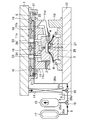
図1に示すプレス加工装置は、プレス機のラム1の下降によってワーク(鋼板)Wをプレス成形する上型(ダイ)2及び下型(パンチ)3と、該プレス成形に続いて各々ワークWの二次加工をする複数の二次加工具4〜7を備えている。上型2及び下型3はホットプレス型であり、加熱したワークWを断面ハット形状に曲げ成形するとともに、該成形に続いてワークWを急冷する。これにより、焼入れされた高張力鋼製プレス成形品が得られる。そして、ワークWのプレス成形後、急冷硬化する前に、二次加工具4〜7によるワークWのトリミング(ワーク周縁部の切除)及びピアッシング(孔開け)が行なわれる。
The press working apparatus shown in FIG. 1 includes an upper die (die) 2 and a lower die (punch) 3 for press-forming a workpiece (steel plate) W by lowering a ram 1 of the press machine, and each workpiece W following the press forming. Are provided with a plurality of secondary processing tools 4-7. The
プレス加工装置では、ラム1に一つの昇降プレート8が昇降自在に支持されている。この昇降プレート8の下面に一つの上ホルダ11が重ね合わせ状態にされて固定され、この上ホルダ11に上記二次加工具4〜7が設けられている。プレス加工装置には、作動液を媒体として二次加工具4〜7を駆動する液圧回路としての油圧回路9が設けられている。この場合、作動液として圧油が用いられていることになる。
In the press working apparatus, one elevating
上型2は、上ホルダ11に対して、相対的に昇降自在に支持されている。下型3はボルスタ12に固定された下ホルダ13に固定されている。
The
以下、プレス加工装置を構成する各要素を具体的に説明する。 Hereinafter, each element which comprises a press work apparatus is demonstrated concretely.
昇降プレート8は、ラム1に固定した支持部材21にリターンスプリング22を介して受けられている。
The elevating
上ホルダ11は、上板部11a、この上板部11aより上型2の両側を下方に延びる延設部11b,11c、並びに、一方の延設部11bの外側に設けられたカムドライバー11dを備えている。昇降プレート8が上ホルダ11の上板部11aに重ね合わされて、該昇降プレート8に上ホルダ11が固定されている。この上ホルダ11には、二次加工具として、ワークWのトリミングを行なうトリム刃4,5と、ワークWに対して垂直にピアッシングする垂直ピアス刃6と、ワークWに対して斜めにピアッシングする斜行ピアス刃7とが設けられている。
The
トリム刃4,5は、上型2の両側を下方に延びる上ホルダ11の延設部11b,11cの下端に固定されている。垂直ピアス刃6は、ワークWの頂部に上方から孔を明けるべく、上ホルダ11の上板部11aに固定されている。斜行ピアス刃7は、ワークWの側部にその側方から孔を明けるべく、上ホルダ11の一方の延設部11bに支持されている。この斜行ピアス刃7は、上ホルダ11のカムドライバー11dの下降力を受けて斜め下方へ前進し、カムドライバー11dが上昇すると、リターンスプリング(図示省略)の付勢によって後退する。
The trim blades 4, 5 are fixed to the lower ends of the extending
下型3には、ワークWのトリミングを行なうためのトリム刃4,5に対応する切刃24,25が設けられ、垂直ピアス刃6及び斜行ピアス刃7各々に対応するダイス26,27が設けられている。
The
昇降プレート8と上ホルダ11には相対する貫通孔が複数形成されており、これらの相対する貫通孔を通してラム1に固定したロッド33と上型2に固定したロッド34が相接触している。これにより、ラム1の下降力がロッド33,34を介して上型2に伝わるようになっている。
A plurality of opposed through holes are formed in the elevating
油圧回路9は、液圧発生シリンダとしての油圧発生シリンダ14と、二次加工用アキュムレータとしての高圧アキュムレータ15と、二次加工具4〜7を二次加工方向に駆動するアクチュエータとしての油圧シリンダ16と、油圧発生シリンダ14を復帰させるための低圧アキュムレータ17と、各々圧油の流路を切り換える第1切換弁18及び第2切換弁19とを備えている。
The
油圧発生シリンダ14は、ワークWをプレス成形するときのラム1の下降エネルギーによって圧油を内部から吐出して油圧を発生するものであり、ラム1とボルスタ12の間に配置されている。図では油圧発生シリンダ14を1本のみ描いているが、金型まわりに適宜の間隔をおいて複数本の油圧発生シリンダ14が設けられている。
The hydraulic
高圧アキュムレータ15は、油圧発生シリンダ14が発生する油圧をガス圧に変換して蓄える。
The
油圧シリンダ16は、ラム1と昇降プレート8の間に設けられており、高圧アキュムレータ15で蓄えられた油圧を受けて昇降プレート8を上ホルダ11と共に下降させる。昇降プレート8は、多数の油圧シリンダ16を前後左右に一定間隔をおいて配置することができるようにした汎用プレートである。本実施形態では、複数本(例えば、60本)の油圧シリンダ16がラム1と昇降プレート8の間に設けられている。昇降プレート8は、油圧シリンダ16への圧油の供給によって上ホルダ11と共に下降し、油圧シリンダ16への圧油の供給が解除されると、すなわち、油圧シリンダ16から圧油が吐出(排出)される状態になると、リターンスプリング22の付勢によってホルダ11と共に上昇する。
The
低圧アキュムレータ17は、リターンスプリング22の付勢による昇降プレート8の上昇(二次加工具4〜7の復帰)に伴って、油圧シリンダ16から圧油が吐出されたとき、その吐出によって生ずる油圧をガス圧に変換して蓄える。
When the pressure oil is discharged from the
油圧回路9は、油圧発生シリンダ14から延びる油路20aを備え、該油路20aは、油圧シリンダ16に延びる油路20bとアキュムレータ15,17側に延びる油路20cとに分岐している。アキュムレータ15,17側に延びる油路20cは、高圧アキュムレータ15に延びる油路20dと低圧アキュムレータ17に延びる油路20eとに分岐している。第1切換弁18は、三方弁であって、油路20a,20b,20cの分岐点に設けられている。第2切換弁19は、三方弁であって、油路20c,20d,20eの分岐点に設けられている。
The
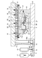
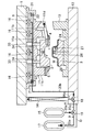
第1及び第2の切換弁18,19は、図示を省略した制御部からの制御信号によりプレス加工装置の作動に応じて油路を選択的に開閉する。図1に示すように、油路20b及び油路20eが閉じられると(図1〜4では、閉じられた油路に「×」を付けている。)、油圧発生シリンダ14から高圧アキュムレータ15に向かって圧油が吐出される流路Aが形成される。図2に示すように、油路20a及び油路20eが閉じられると、高圧アキュムレータ15から油圧シリンダ16に向かって圧油が吐出される流路Bが形成される。図3に示すように、油路20a及び油路20dが閉じられると、油圧シリンダ16から低圧アキュムレータ17に向かって圧油が吐出される流路Cが形成される。図4に示すように、油路20b及び油路20dが閉じられると、低圧アキュムレータ17から油圧発生シリンダ14に向かって圧油が吐出される流路Dが形成される。
The first and
ここに、第1及び第2の切換弁18,19は、プレス成形時(ラム1の下降時)には流路A(図1)が形成され、プレス成形に続く二次加工時(昇降プレート8の下降時)には流路B(図2)が形成され、二次加工後の二次加工具4〜7の復帰時(リターンスプリング22の付勢による昇降プレート8の上昇時)には流路C(図3)が形成され、ラム1の上昇時には流路D(図4)が形成されるように制御される。第1及び第2の切換弁18,19は、本発明の流路切換手段を構成している。
Here, the first and
上記プレス加工装置ではプレス成形品の冷却に水冷が採用されている。図示は省略するが、上型2及び下型3各々には冷却水通路が形成され、各々のワークWを成形する成形面に冷却水の噴出口と冷却水の吸込口が開口している。上型2及び下型3各々の成形面とプレス成形品の間に冷却水を供給することで、プレス成形品を急冷して焼き入れする。なお、上型2及び下型3各々に冷却水通路を形成し、冷却水を噴出させることなく、上型2及び下型3を介してプレス成形品を間接的に水冷することもできる。
In the press working apparatus, water cooling is adopted for cooling the press-formed product. Although illustration is omitted, a cooling water passage is formed in each of the
−プレス加工装置の作動−
図1に示すように、ワークWを上型2と下型3の間に搬入した状態でラム1を下降させると、上型2がロッド33,34を介してラム1で押されて下降する。これにより、ワークWは上型2と下型3に挟まれて上向きの凸になるように変形していく。このときは、流路Aが形成されるように第1及び第2の切換弁18,19が切り換えられる。これにより、ラム1の下降に伴って油圧発生シリンダ14から流路A(油路20a,20c,20d)を介して高圧アキュムレータ15に向かって圧油が吐出される。よって、油圧発生シリンダ14が発生する油圧が高圧アキュムレータ15に蓄えられる。
-Operation of press working equipment-
As shown in FIG. 1, when the ram 1 is lowered while the workpiece W is carried between the
図2に示すように、上記上型2の下降により、ワークWはハット状にプレス成形された状態になる。その状態で、上型2及び下型3への冷却水の供給によるワークWの冷却が開始される。同時に、流路Bが形成されるように第1及び第2の切換弁18,19が切り換えられる。これにより、高圧アキュムレータ15から流路B(油路20d,20c,20b)を介して油圧シリンダ16に向かって圧油が吐出される。すなわち、油圧シリンダ16が流路Bを介して高圧アキュムレータ15の油圧を受けて伸び、その伸び推力によって昇降プレート8が上ホルダ11と共に下降する。
As shown in FIG. 2, when the
これにより、トリム刃4,5によってワークWのトリミングが行なわれるとともに、垂直ピアス刃6及び斜行ピアス刃7によるワークWのピアッシングが行なわれる(二次加工)。油圧回路9の作動油は実質的に非圧縮性の媒体であるから、上記流路の切換によって、高圧アキュムレータ15から複数本の油圧シリンダ16各々に対して直ちに油圧が伝わり、二次加工具が応答性良く駆動されることになる。この時点では、ワークWは冷却の途中段階であって未だ焼入れ硬化していないから、過大な力を要することなく、ワークWの二次加工を行なうことができる。
Thus, the workpiece W is trimmed by the trim blades 4 and 5, and the workpiece W is pierced by the vertical piercing
二次加工後、図3に示すように、流路Cが形成されるように第1及び第2の切換弁18,19が切り換えられる。その結果、油圧シリンダ16から流路C(油路20b,20c,20e)を介して低圧アキュムレータ17に向かって圧油が吐出(排出)されることになる。これにより、昇降プレート8が上ホルダ11と共にリターンスプリング22の付勢によって上昇し、トリム刃4,5、垂直ピアス刃6及び斜行ピアス刃7が元位置に復帰する。そして、リターンスプリング22の付勢力によって油圧シリンダ16から吐出される圧油の圧力がガス圧に変換されて低圧アキュムレータ17に蓄えられる。
After the secondary processing, as shown in FIG. 3, the first and
次いで、ワークWの焼入れのための冷却水の供給が停止された後、図4に示すように、ラム1を上昇させる。これにより、プレス成形及び二次加工が施されたワークWの取出しが可能になる。このとき、流路Dが形成されるように第1及び第2の切換弁18,19が切り換えられる。これにより、低圧アキュムレータ17から流路D(油路20e,20c,20a)を介して油圧発生シリンダ14に向かって圧油が吐出される。その結果、油圧発生シリンダ14が圧油を内部に蓄えながら伸びる。よって、油圧発生シリンダ14は、次にラム1が下降するときに、その下降エネルギーによって油圧を発生することが可能になる。
Next, after the supply of cooling water for quenching the workpiece W is stopped, the ram 1 is raised as shown in FIG. Thereby, it is possible to take out the workpiece W subjected to press molding and secondary processing. At this time, the first and
上述の如く、高圧アキュムレータ15は、油圧をガス圧に変換して蓄えるものであるから、該高圧アキュムレータ15と油圧シリンダ16を結ぶ油路に存する媒体を圧縮する必要がない。従って、高圧アキュムレータ15は、油圧シリンダ16自体への供給に必要な量の圧油を蓄えることで足りるから、その小型化に有利になる。特に、実施例のように、多数の油圧シリンダ16を設ける場合において、高圧アキュムレータ15の大型化を避けることができる。同じ理由から、油圧発生シリンダ14も、油圧シリンダ16自体への供給に必要な油量を吐出し得ることで足りるから、その小型化に有利になる。
As described above, the high-
また、低圧アキュムレータ17は、油圧をガス圧に変換して蓄えるものであるから、油圧発生シリンダ14や油圧シリンダ16と低圧アキュムレータ17とを結ぶ油路に存する媒体を圧縮する必要がない。従って、油圧発生シリンダ14や低圧アキュムレータ17の小型化に有利になるとともに、二次加工具4〜7がリターンスプリング22の付勢力によって復帰するときに油圧シリンダ16から低圧アクチュエータ17に油圧が確実に蓄えられ、その油圧によって油圧発生シリンダ14が元位置に確実に復帰することになる。
Further, since the
このように、二次加工具4〜7のリターンスプリング22による復帰力を利用して油圧発生シリンダ14を復帰させるから、油圧発生シリンダ14の復帰のために、オイルポンプ等の油圧発生源を別に設ける必要がなく、或いは、油圧発生シリンダ14自体にリターンスプリングを設ける必要はない。よって、プレス加工装置の省エネルギー化に有利になる。例えば、油圧発生シリンダ14自体にリターンスプリングを設けた場合、ラム1の下降エネルギーによって油圧を発生させるときに、リターンスプリングを圧縮するために余分なエネルギーが必要になるところ、それが不要になる。
As described above, the hydraulic
なお、上記実施形態は、ホットプレスに関するが、本発明は冷間プレス加工にも適用することができる。 Although the above embodiment relates to hot pressing, the present invention can also be applied to cold pressing.
また、二次加工具としては、トリミング及びピアッシングに限らず、バーリング用、ベンディング用、コイニング用等の加工具であってもよい。 The secondary processing tool is not limited to trimming and piercing, and may be a processing tool for burring, bending, coining, or the like.
1 ラム
2 上型
3 下型
4〜7 二次加工具
8 昇降プレート
9 油圧回路(液圧回路)
11 上ホルダ
14 油圧発生シリンダ(液圧発生シリンダ)
15 高圧アキュムレータ
16 油圧シリンダ(アクチュエータ)
18 第1切換弁(切換手段)
19 第2切換弁(切換手段)
A〜D 油路(流路)
W ワーク
1
11
15
18 1st switching valve (switching means)
19 Second switching valve (switching means)
AD oil path (flow path)
W Work
Claims (4)
プレス機のラムの下降によって上記ワークをプレス成形する上型及び下型と、
上記ワークの二次加工をする二次加工具と、
上記二次加工具を復帰させるリターンスプリングと、
作動液を媒体として上記二次加工具を駆動する液圧回路とを備え、
上記液圧回路は、
上記ラムの下降エネルギーによって上記作動液を吐出する液圧発生シリンダと、
上記液圧発生シリンダが発生する液圧をガス圧に変換して蓄えるアキュムレータと、
上記アキュムレータで蓄えられた液圧によって上記二次加工具を二次加工方向に駆動するアクチュエータと、
上記作動液の流路を、上記アキュムレータに液圧が蓄えられるように上記液圧発生シリンダから作動液を吐出させる流路と、上記アクチュエータが上記二次加工具を駆動するように上記アキュムレータから作動液を吐出させる流路と、上記リターンスプリングの付勢によって上記二次加工具が復帰するように上記アクチュエータから作動液を吐出させる流路とに切り換える切換手段とを備えていることを特徴とするプレス加工装置。 A press working apparatus that performs press forming of a workpiece and secondary processing of the workpiece,
An upper die and a lower die for press-molding the workpiece by lowering the ram of the press machine;
A secondary processing tool for secondary processing of the workpiece;
A return spring for returning the secondary processing tool;
A hydraulic circuit that drives the secondary processing tool using hydraulic fluid as a medium;
The hydraulic circuit is
A hydraulic pressure generating cylinder that discharges the hydraulic fluid by lowering energy of the ram;
An accumulator that converts the hydraulic pressure generated by the hydraulic pressure generating cylinder into a gas pressure and stores it;
An actuator for driving the secondary processing tool in the secondary processing direction by the hydraulic pressure stored in the accumulator;
The hydraulic fluid passage is operated from the accumulator so that the hydraulic fluid is discharged from the hydraulic pressure generating cylinder so that the hydraulic pressure is stored in the accumulator, and the actuator drives the secondary processing tool. And a switching means for switching between a flow path for discharging the liquid and a flow path for discharging the hydraulic fluid from the actuator so that the secondary processing tool is restored by the urging of the return spring. Press processing equipment.
上記上型及び下型は、加熱された上記ワークのプレス成形と、該プレス成形に続いて当該ワークの焼入れのための冷却とを行なうホットプレス型であり、
上記切換手段は、上記ワークのプレス成形後、該ワークが焼入れによって硬化する前に、上記作動液の流路を、上記液圧発生シリンダから作動液を吐出させる流路から、上記アキュムレータから作動液を吐出させる流路に切り換えることを特徴とするプレス加工装置。 In claim 1,
The upper mold and the lower mold are hot press molds that perform press molding of the heated workpiece and cooling for quenching the workpiece following the press molding,
The switching means is configured such that after the work is press-molded and before the work is hardened by quenching, the working fluid passage is connected to the working fluid from the accumulator. The press working apparatus is characterized in that it is switched to a flow path for discharging water.
上記二次加工具は、上記上型に対して相対的に昇降するように設けられたホルダに支持され、該ホルダが上記上型に対して相対的に下降することにより、上記ワークの二次加工を行なうものであり、
上記ホルダを上記上型に対して相対的に下降させるために、上記ラムと上記ホルダの間に上記アクチュエータとしての液圧シリンダが複数本設けられていることを特徴とするプレス加工装置。 In claim 1 or claim 2,
The secondary processing tool is supported by a holder provided so as to move up and down relatively with respect to the upper mold, and the holder lowers relative to the upper mold, whereby the secondary work tool Processing,
A press working apparatus, wherein a plurality of hydraulic cylinders as the actuator are provided between the ram and the holder to lower the holder relative to the upper mold.
上記二次加工具として、上記ワークのトリミングを行なう加工具と、上記ワークのピアッシングを行なう加工具とを備え、
上記両加工具が上記ホルダに支持され、上記ワークのプレス成形に続いて当該両加工具による上記ワークのトリミングとピアッシングが同時に行なわれることを特徴とするプレス加工装置。 In claim 3,
As the secondary processing tool, a processing tool for trimming the workpiece, and a processing tool for piercing the workpiece,
The press working apparatus, wherein both the processing tools are supported by the holder, and trimming and piercing of the work by both the processing tools are performed simultaneously with press forming of the work.
Priority Applications (1)
| Application Number | Priority Date | Filing Date | Title |
|---|---|---|---|
| JP2016036376A JP6299787B2 (en) | 2016-02-26 | 2016-02-26 | Press machine |
Applications Claiming Priority (1)
| Application Number | Priority Date | Filing Date | Title |
|---|---|---|---|
| JP2016036376A JP6299787B2 (en) | 2016-02-26 | 2016-02-26 | Press machine |
Publications (2)
| Publication Number | Publication Date |
|---|---|
| JP2017148860A true JP2017148860A (en) | 2017-08-31 |
| JP6299787B2 JP6299787B2 (en) | 2018-03-28 |
Family
ID=59738728
Family Applications (1)
| Application Number | Title | Priority Date | Filing Date |
|---|---|---|---|
| JP2016036376A Expired - Fee Related JP6299787B2 (en) | 2016-02-26 | 2016-02-26 | Press machine |
Country Status (1)
| Country | Link |
|---|---|
| JP (1) | JP6299787B2 (en) |
Cited By (4)
| Publication number | Priority date | Publication date | Assignee | Title |
|---|---|---|---|---|
| CN107537934A (en) * | 2017-10-21 | 2018-01-05 | 浙江博鑫涵汽车零部件有限公司 | A kind of diel |
| CN107584016A (en) * | 2017-10-21 | 2018-01-16 | 浙江博鑫涵汽车零部件有限公司 | The diel of sheet metal |
| CN109500239A (en) * | 2019-01-22 | 2019-03-22 | 重庆至信实业集团有限公司 | A kind of battery box support reinforcer process units |
| CN109570345A (en) * | 2019-01-16 | 2019-04-05 | 重庆至信实业集团有限公司 | A kind of spare tyre reinforcer process units |
Citations (7)
| Publication number | Priority date | Publication date | Assignee | Title |
|---|---|---|---|---|
| JPS6040621A (en) * | 1983-08-11 | 1985-03-04 | Nissan Motor Co Ltd | Press die |
| US5038598A (en) * | 1990-09-07 | 1991-08-13 | Gene Pitzer | Method and apparatus for performing secondary operations in a press |
| JPH05237564A (en) * | 1992-02-27 | 1993-09-17 | Toyota Motor Corp | Method for simultaneously working bending and punching and device therefor |
| JPH08132299A (en) * | 1994-11-04 | 1996-05-28 | Toyota Motor Corp | Press device |
| JP2000158057A (en) * | 1998-11-26 | 2000-06-13 | Toyota Auto Body Co Ltd | Press die |
| JP2005248253A (en) * | 2004-03-04 | 2005-09-15 | Unipres Corp | Method and apparatus for hot-pressing steel material |
| WO2014162350A1 (en) * | 2013-04-02 | 2014-10-09 | 株式会社キーレックス | Press apparatus |
-
2016
- 2016-02-26 JP JP2016036376A patent/JP6299787B2/en not_active Expired - Fee Related
Patent Citations (7)
| Publication number | Priority date | Publication date | Assignee | Title |
|---|---|---|---|---|
| JPS6040621A (en) * | 1983-08-11 | 1985-03-04 | Nissan Motor Co Ltd | Press die |
| US5038598A (en) * | 1990-09-07 | 1991-08-13 | Gene Pitzer | Method and apparatus for performing secondary operations in a press |
| JPH05237564A (en) * | 1992-02-27 | 1993-09-17 | Toyota Motor Corp | Method for simultaneously working bending and punching and device therefor |
| JPH08132299A (en) * | 1994-11-04 | 1996-05-28 | Toyota Motor Corp | Press device |
| JP2000158057A (en) * | 1998-11-26 | 2000-06-13 | Toyota Auto Body Co Ltd | Press die |
| JP2005248253A (en) * | 2004-03-04 | 2005-09-15 | Unipres Corp | Method and apparatus for hot-pressing steel material |
| WO2014162350A1 (en) * | 2013-04-02 | 2014-10-09 | 株式会社キーレックス | Press apparatus |
Cited By (6)
| Publication number | Priority date | Publication date | Assignee | Title |
|---|---|---|---|---|
| CN107537934A (en) * | 2017-10-21 | 2018-01-05 | 浙江博鑫涵汽车零部件有限公司 | A kind of diel |
| CN107584016A (en) * | 2017-10-21 | 2018-01-16 | 浙江博鑫涵汽车零部件有限公司 | The diel of sheet metal |
| CN109570345A (en) * | 2019-01-16 | 2019-04-05 | 重庆至信实业集团有限公司 | A kind of spare tyre reinforcer process units |
| CN109570345B (en) * | 2019-01-16 | 2023-10-31 | 重庆至信实业集团有限公司 | Spare tire reinforcement production device |
| CN109500239A (en) * | 2019-01-22 | 2019-03-22 | 重庆至信实业集团有限公司 | A kind of battery box support reinforcer process units |
| CN109500239B (en) * | 2019-01-22 | 2023-12-15 | 重庆至信实业集团有限公司 | Battery box support reinforcement apparatus for producing |
Also Published As
| Publication number | Publication date |
|---|---|
| JP6299787B2 (en) | 2018-03-28 |
Similar Documents
| Publication | Publication Date | Title |
|---|---|---|
| JP6299787B2 (en) | Press machine | |
| JP5047053B2 (en) | Equipment for hydroforming metal elements | |
| JP5982560B2 (en) | Press machine | |
| KR20100024374A (en) | Method and device for controlling the synchronization of cylinder/piston units and for reducing pressure peaks during forming and/or fineblanking on a fineblanking or stamping press | |
| JP2005248253A (en) | Method and apparatus for hot-pressing steel material | |
| US9919353B2 (en) | Method and device for precision cutting of workpieces in a press | |
| CN102284626A (en) | Mold structure for switching punching part state and switching method | |
| CN103706713B (en) | Punching die and hole-punching and switching mechanism thereof | |
| JP6123810B2 (en) | Double-acting system for forging dies | |
| JP6299786B2 (en) | Press machine | |
| JP2012066293A (en) | Press forming apparatus | |
| JP4588553B2 (en) | Forging method and double-action die apparatus for forging | |
| JP4129621B2 (en) | Press mold | |
| JP3213661U (en) | Processing equipment | |
| JP4442234B2 (en) | Hydraulic forming apparatus for laminated plate material, its hydraulic forming mold, and its hydraulic forming method | |
| CN212495144U (en) | Forging device with ejection mechanism | |
| CN210190684U (en) | Hydraulic fine blanking machine | |
| CN110935778B (en) | Multifunctional testing machine and use method thereof | |
| JP2000351024A (en) | Turret punch press | |
| CN208853504U (en) | A kind of servo locking mechanism, buffer unit and punching machine | |
| CN211489259U (en) | Punch forming die with trimming process | |
| JP6010756B2 (en) | Multi-stage press machine | |
| JP7113624B2 (en) | Press molding equipment | |
| JP2011189367A (en) | Mold for ejecting forged pin and method thereof | |
| JP5796710B2 (en) | Press machine |
Legal Events
| Date | Code | Title | Description |
|---|---|---|---|
| A977 | Report on retrieval |
Free format text: JAPANESE INTERMEDIATE CODE: A971007 Effective date: 20171010 |
|
| A131 | Notification of reasons for refusal |
Free format text: JAPANESE INTERMEDIATE CODE: A131 Effective date: 20171121 |
|
| A521 | Request for written amendment filed |
Free format text: JAPANESE INTERMEDIATE CODE: A523 Effective date: 20180116 |
|
| TRDD | Decision of grant or rejection written | ||
| A01 | Written decision to grant a patent or to grant a registration (utility model) |
Free format text: JAPANESE INTERMEDIATE CODE: A01 Effective date: 20180130 |
|
| A61 | First payment of annual fees (during grant procedure) |
Free format text: JAPANESE INTERMEDIATE CODE: A61 Effective date: 20180212 |
|
| R150 | Certificate of patent or registration of utility model |
Ref document number: 6299787 Country of ref document: JP Free format text: JAPANESE INTERMEDIATE CODE: R150 |
|
| LAPS | Cancellation because of no payment of annual fees |