JP2017146264A - Automatic analyzer - Google Patents
Automatic analyzer Download PDFInfo
- Publication number
- JP2017146264A JP2017146264A JP2016029991A JP2016029991A JP2017146264A JP 2017146264 A JP2017146264 A JP 2017146264A JP 2016029991 A JP2016029991 A JP 2016029991A JP 2016029991 A JP2016029991 A JP 2016029991A JP 2017146264 A JP2017146264 A JP 2017146264A
- Authority
- JP
- Japan
- Prior art keywords
- maintenance
- analysis
- unit
- automatic
- automatic analyzer
- Prior art date
- Legal status (The legal status is an assumption and is not a legal conclusion. Google has not performed a legal analysis and makes no representation as to the accuracy of the status listed.)
- Granted
Links
Images


Abstract
Description
本発明は、血液や尿などの生体試料の定性・定量分析を行う自動分析装置に関する。 The present invention relates to an automatic analyzer that performs qualitative and quantitative analysis of biological samples such as blood and urine.
血液や尿等の生体試料(以下、単に試料と称する)と試薬とを用いることによって試料に含まれる特定成分の定量・定性分析を行う自動分析装置では、装置コンディションの維持を目的とした保守作業や、装置運用に必要な試薬や洗浄液などの消耗品の補充作業などのメンテナンスを実施することにより、分析結果の信頼性や作業効率の維持を図っている。しかしながら、自動分析装置のメンテナンスには多種多様な作業が含まれているため、オペレータやサービスエンジニアなどが手動で実施するには大きな負担となる。 In automatic analyzers that perform quantitative and qualitative analysis of specific components contained in samples by using biological samples such as blood and urine (hereinafter simply referred to as samples) and reagents, maintenance work for the purpose of maintaining device conditions In addition, the maintenance of reliability of analysis results and work efficiency is achieved by performing maintenance such as replenishment of consumables such as reagents and cleaning liquids necessary for the operation of the apparatus. However, since maintenance of an automatic analyzer involves a wide variety of operations, it is a heavy burden for operators, service engineers, and the like to perform it manually.
そこで、自動分析装置におけるメンテナンスの負担軽減を目的として、例えば、特許文献1(特開2015−108641号公報)には、メンテナンス項目毎に実施を推奨する間隔とメンテナンスを構成する複数の手順要素を記憶する記憶手段と、メンテナンスの実施指示を受けて、指示が出された時点で記憶手段に記憶されたメンテナンスの実施間隔に基づいて実施すべきメンテナンス項目を抽出する抽出手段と、抽出手段で抽出されたメンテナンス項目に対する複数の手順要素を、予め定められたルールに基づき、並べ替える並べ替え手段とを備え、予め定められたルールは、抽出されたメンテナンス項目に対する複数の手順要素に、同じ手順要素がある場合は、手順要素を一つにするように並び替え、並び替えは、抽出したメンテナンス項目である反応系洗浄と反応セル交換を実施する際に、反応系洗浄と反応セル交換に含まれる同じ手順要素である反応系洗浄とセルブランク測定の実行を一つにするように手順要素を並び替える臨床検査用分析装置が開示されている。 Therefore, for the purpose of reducing the maintenance burden in the automatic analyzer, for example, Patent Document 1 (Japanese Patent Application Laid-Open No. 2015-108641) includes a plurality of procedural elements constituting an interval and maintenance recommended for each maintenance item. Storage means for storing, extraction means for extracting maintenance items to be performed based on the maintenance execution interval stored in the storage means at the time when the instruction is issued upon receiving the instruction for maintenance, and extraction by the extraction means Reordering means for reordering a plurality of procedural elements for the maintenance item based on a predetermined rule, and the predetermined rule is the same procedural element as the plurality of procedural elements for the extracted maintenance item. If there is, reorder the procedure elements to be one, and reorder the extracted maintenance When performing the system cleaning and reaction cell replacement, which are the items, procedural elements should be integrated so that the same system elements included in the system cleaning and reaction cell replacement are the same. A rearranging clinical laboratory analyzer is disclosed.
しかしながら、上記従来技術には以下のような問題点がある。 However, the above prior art has the following problems.
近年の検査センターなどにおける自動分析装置の運用では、装置を測定可能な状態で24時間継続運転しつつ測定対象の試料を順次投入して大量測定を行い、効率化を図る場合が多くなっている。その一方でメンテナンスは基本的に装置の停止状態で行う必要がありメンテナンスの実行中は試料の測定が行えないため、メンテナンスの実行タイミングによっては検査効率が低下してしまうことが考えられる。また、サービスエンジニアを含むオペレータによるメンテナンスの起動作業が必要であるため、メンテナンスの開始時にはオペレータが対象の装置に拘束されることとなり、作業効率の低下が懸念される。 In the operation of automatic analyzers in recent inspection centers and the like, there are many cases in which mass measurement is performed by sequentially introducing samples to be measured while continuously operating the apparatus for 24 hours in a state where the apparatus can be measured. . On the other hand, the maintenance must basically be performed while the apparatus is stopped, and the sample cannot be measured while the maintenance is being performed. Therefore, the inspection efficiency may be reduced depending on the maintenance execution timing. In addition, since a maintenance start operation by an operator including a service engineer is necessary, the operator is restrained by the target device at the start of the maintenance, and there is a concern that work efficiency may be reduced.
本発明は上記に鑑みてなされたものであり、検査効率や作業効率の低下を抑制しつつメンテナンスを実施することにより、分析結果の信頼性を維持することができる自動分析装置を提供することを目的とする。 The present invention has been made in view of the above, and provides an automatic analyzer that can maintain the reliability of analysis results by performing maintenance while suppressing a decrease in inspection efficiency and work efficiency. Objective.
上記目的を達成するために、本発明は、分析対象である試料を収容した1つ以上の試料容器を搭載した検体ラックを投入する検体ラック投入部と検体ラック回収部との間で前記検体ラックを搬送する検体ラック搬送ラインと、前記検体ラック搬送ラインに沿って配置され、少なくとも、試料を反応容器に分注する試料分注機構、試薬を前記反応容器に分注する試薬分注機構、及び前記反応容器に収容された試料と試薬の混合液を測定する測定機構を含む複数の分析要素によって分析処理を行う1つ以上の分析ユニットと、前記分析ユニットを構成する複数の分析要素のメンテナンス処理について、少なくとも1つのメンテナンス処理を含む複数のメンテナンスグループを定義し、前記分析ユニットの動作状態に関して予め定めた判定開始条件が満たされた場合に、前記メンテナンスグループのそれぞれについて予め定めたメンテナンス実行条件の到達率が予め定めた閾値を超えているメンテナンスグループのメンテナンス処理を実行する制御部とを備えたものとする。 In order to achieve the above object, the present invention provides the sample rack between a sample rack loading unit and a sample rack collection unit for loading a sample rack on which one or more sample containers containing a sample to be analyzed are mounted. A sample rack transport line that transports the sample, a sample dispensing mechanism that is disposed along the sample rack transport line, and dispenses a sample into the reaction container, a reagent dispensing mechanism that dispenses a reagent into the reaction container, and One or more analysis units that perform an analysis process using a plurality of analysis elements including a measurement mechanism that measures a mixed solution of a sample and a reagent contained in the reaction container, and a maintenance process for the plurality of analysis elements that constitute the analysis unit A plurality of maintenance groups including at least one maintenance process, and a determination start condition predetermined for the operating state of the analysis unit When filled, and that a control unit for executing maintenance processing of the maintenance groups arrival rate of a predetermined maintenance execution conditions for each of the maintenance group exceeds a predetermined threshold.
本発明によれば、検査効率や作業効率の低下を抑制しつつメンテナンスを実施することにより、分析結果の信頼性を維持することができる。 According to the present invention, the reliability of the analysis result can be maintained by performing maintenance while suppressing a decrease in inspection efficiency and work efficiency.
本発明の実施の形態を図面を参照しつつ説明する。 Embodiments of the present invention will be described with reference to the drawings.
<第1の実施の形態>
本発明の第1の実施の形態を図1〜図7を参照しつつ説明する。
<First Embodiment>
A first embodiment of the present invention will be described with reference to FIGS.
図1は、本実施の形態に係る自動分析装置の全体構成を概略的に示す図である。 FIG. 1 is a diagram schematically showing an overall configuration of an automatic analyzer according to the present embodiment.
図1において、自動分析装置100は、分析対象である血液や尿などの生体試料(以下、試料と称する)を収容した1つ以上の試料容器を搭載した検体ラックを投入する検体ラック投入部1と、分析処理の終了した検体ラックを回収する検体ラック回収部10と、検体ラック投入部1と検体ラック回収部10との間で検体ラックを搬送する検体ラック搬送ライン3と、検体ラック搬送ライン3の下流側端部から上流側端部に検体ラックを搬送する再検査用搬送ライン4と、検体ラック投入部1から検体ラック搬送ライン3に送出される検体ラックの個体識別子(例えば、バーコードやRFID)から個体識別情報を読み取るID読取部2と、検体ラック搬送ラインに沿って配置され、少なくとも、試料を反応容器に分注する試料分注機構、試薬を反応容器に分注する試薬分注機構、及び反応容器に収容された試料と試薬の混合液を測定する測定機構を含む複数の分析要素によって分析処理を行う1つ以上(本実施の形態では4つ)の分析ユニット5,6,7,8と、再検査用搬送ライン4または検体ラック回収部10に搬送される前の検体ラックを待機させる検体ラック待機部9と、検体ラック投入部1、分析ユニット5〜8、及び検体ラック待機部9をそれぞれ制御する制御用コンピュータ12,13,14,15,16,17と、自動分析装置100全体の動作を制御する制御部11とから概略構成されている。
In FIG. 1, an
制御部11には、動作指令や設定値などを入力するための操作部18と、分析処理やメンテナンス処理などに係る種々の設定画面を表示するための表示部19とが設けられており、操作部18と表示部19により自動分析装置100の操作を行うためのGUI(Graphical User Interface)が構成されている。
The control unit 11 is provided with an
分析ユニット5〜8は、搬送ライン3から検体ラックを引き込むための検体ラック引込線51,61,71,81をそれぞれ有しており、分析対象となる試料を収容した検体を搭載した検体ラックを引き込んで分析処理を実施する。
The
なお、本実施の形態では分析ユニット5〜8が全て生化学分析ユニットである場合を例示して説明しているが、これに限られず、分析ユニット5〜8としては種々の組合せが可能である。分析ユニット5〜8としては、例えば、生化学分析ユニットのほかに、電解質分析ユニットなどを用いてもよい。
In the present embodiment, the case where the
ここで、自動分析装置のメンテナンス処理について説明する。 Here, the maintenance process of the automatic analyzer will be described.
図2は自動分析装置の起動からメンテナンス処理の実行までの基本的な流れを示すフローチャートであり、図3は自動メンテナンス設定画面の一例を示す図である。なお、以降の説明では、分析ユニット5〜8のうちの異なる2つをそれぞれ第1分析ユニット及び第2分析ユニットと称して説明する。
FIG. 2 is a flowchart showing a basic flow from activation of the automatic analyzer to execution of maintenance processing, and FIG. 3 is a diagram showing an example of an automatic maintenance setting screen. In the following description, two different ones of the
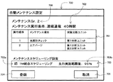
図3に示す自動メンテナンス設定画面300は、制御部11の表示部19に表示され、操作部18によって自動メンテナンスに係る設定を定義・登録するものであり、メンテナンスグループ名設定部305、メンテナンス実行条件設定部302、メンテナンス項目設定部301、登録ボタン303、取消ボタン304などから構成されている。
An automatic
図3においては、メンテナンスグループ名として「Gr.1」を登録する場合を例示している。メンテナンス実行条件設定部302には、メンテナンス処理が実行される条件として、30時間の連続通電が設定されている。メンテナンス項目設定部301には、メンテナンスグループに加入されるメンテナンス項目と、実行順序と、対象となる分析ユニットとが設定されており、第1及び第2分析ユニットの反応槽水交換、第1及び第2分析ユニットのセルブランク測定、第1分析ユニットの光度計チェックの実行順序でメンテナンス項目が設定されている。各設定部301,302,305に入力された情報は登録ボタン303が選択されることにより制御部11の図示しない記憶部に登録される。また、取消ボタン304が選択されることにより、各設定部301,302,305の入力内容は取り消される。同様の操作により、他のメンテナンス項目を含む他のメンテナンスグループを複数登録することが可能である。
FIG. 3 illustrates a case where “Gr.1” is registered as the maintenance group name. In the maintenance execution
例えば、図3では、第1分析ユニットのみメンテナンス実行条件を満たした場合には反応槽水交換、セルブランク測定及び光度計チェックの順でメンテナンス処理を実施し、また、第2分析ユニットのみメンテナンス実行条件を満たした場合には反応槽水交換、セルブランク測定の順にメンテナンス処理を実行する。また、第1ユニットと第2分析ユニットが同時にメンテンナンス実行条件を満たした場合には各分析ユニット個別に定義されたメンテナンス処理を同時に実行する。なお、メンテナンス処理の実行中は、複数の分析ユニットを有する自動分析装置の場合、他の分析ユニットでの分析を継続する。また、メンテナンス処理を実行中の分析ユニットにおいて分析予定の試料容器を搭載した検体ラックはメンテナンス処理の完了まで装置内で待機し、メンテナンス処理の完了後に分析処理を再開する。 For example, in FIG. 3, when only the first analysis unit satisfies the maintenance execution conditions, the maintenance process is performed in the order of reactor water exchange, cell blank measurement, and photometer check, and only the second analysis unit is maintained. When the conditions are satisfied, the maintenance process is performed in the order of reaction tank water exchange and cell blank measurement. Further, when the first unit and the second analysis unit satisfy the maintenance execution condition at the same time, the maintenance process defined for each analysis unit is simultaneously executed. Note that during the maintenance process, in the case of an automatic analyzer having a plurality of analysis units, the analysis in another analysis unit is continued. In addition, the sample rack loaded with the sample container to be analyzed in the analysis unit that is performing the maintenance process waits in the apparatus until the maintenance process is completed, and resumes the analysis process after the maintenance process is completed.
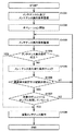
図2に示すように、自動分析装置100の停止状態(スタンバイ状態)において、制御部11は、まず、操作部18及び表示部19によって自動メンテナンス設定画面300で設定されたメンテナンスグループ(メンテナンスグループ名305、メンテナンス項目301)及びメンテナンス実行条件302を登録し(ステップS201)、自動分析装置100を停止状態(スタンバイ状態)からサンプル測定が可能な状態(オペレーション状態)に移行して、試料の分析処理などのオペレーションを開始する(ステップS202)。続いて、ステップS201で登録した自動メンテナンス設定のそれぞれについてメンテナンス実行条件に係る情報を自動分析装置100の各部から取得して監視し(ステップS203)、メンテナンス実行条件が成立したかどうかを判定する(ステップS204)。ステップS204での判定結果がNOの場合、すなわち、メンテナンス実行条件が成立していない間は、ステップS203を繰り返し、メンテナンス実行条件の監視を続ける。例えば、図3においては、連続通電時間が30時間に達したかどうかを監視している。また、ステップS204での判定結果がYESの場合には、自動メンテナンスを実行し(ステップS205)、処理を終了する。
As shown in FIG. 2, when the
図4は、試料の分析処理中にメンテナンス実行条件が成立した場合のメンテナンス処理の基本的な流れを示すフローチャートである。 FIG. 4 is a flowchart showing a basic flow of the maintenance process when the maintenance execution condition is satisfied during the sample analysis process.
図4に示すように、自動分析装置100の分析処理中において、制御部11は、まず、メンテナンス実行条件が成立した分析ユニットへの検体ラックの投入及びサンプル分注を停止して、対象となる分析ユニットでの以降の分析処理を停止する(ステップS401)。続いて、対象分析ユニットで測定中の項目があるかどうかを判定する(ステップS402)。ステップS402での判定結果がYESの場合には、メンテナンス処理の実行を待機しつつ(ステップS403)、測定結果の出力が完了したかどうかを判定し(ステップS404)、判定結果がYESになるまでステップS403の待機を行う。また、ステップS402での判定結果がNOの場合、及び、ステップS404での判定結果がYESの場合には、メンテナンス処理の開始準備動作(メンテナンス開始準備動作)を行う(ステップS405)。メンテナンス開始準備動作では、それまで実施していたサンプル測定に伴う洗浄動作や各機構動作の停止等を行い、メンテナンス処理の実行可能な状態にする。ステップS405のメンテナンス開始準備動作が終了すると、自動メンテナンス設定画面300での設定内容に基づいてメンテナンス処理を順次実行する(ステップS406)。続いて、各測定系のコンディショニング動作や各機構の分析開始準備等である測定開始準備動作を実施し(ステップS407)、メンテナンス処理の対象となった分析ユニットへの検体ラックの投入及び分析処理を開始し(ステップS408)、処理を終了する。
As shown in FIG. 4, during the analysis processing of the
本実施の形態に係る自動分析装置は、以上のような基本構成に加えて、メンテナンス統合処理を実施することにより、検査効率や作業効率の低下を抑制しつつメンテナンスを実施している。メンテナンス統合処理とは、複数のメンテナンスグループが不連続に実施される場合に、予め設定した条件に応じてメンテナンス処理を統合することにより効率化を図るものである。 The automatic analyzer according to the present embodiment performs maintenance while suppressing a decrease in inspection efficiency and work efficiency by performing maintenance integration processing in addition to the basic configuration as described above. The maintenance integration process is to improve efficiency by integrating maintenance processes according to preset conditions when a plurality of maintenance groups are performed discontinuously.
図5はメンテナンス統合処理を含むメンテナンス処理の実行までの流れを示すフローチャートであり、図6及び図7はメンテナンス統合処理に対応した自動メンテナンス設定画面の一例をそれぞれ示す図である。 FIG. 5 is a flowchart showing a flow up to the execution of the maintenance process including the maintenance integration process, and FIGS. 6 and 7 are diagrams each showing an example of an automatic maintenance setting screen corresponding to the maintenance integration process.
図6及び図7に示す自動メンテナンス設定画面600,700は、制御部11の表示部19に表示され、操作部18によって自動メンテナンスに係る設定を定義・登録するものである。
The automatic maintenance setting screens 600 and 700 shown in FIGS. 6 and 7 are displayed on the
自動メンテナンス設定画面600は、メンテナンスグループ名設定部606、メンテナンス実行条件設定部602、メンテナンス項目設定部601、メンテナンススケジューリング設定部603、登録ボタン604、取消ボタン605などから構成されている。また、自動メンテナンス設定画面700も同様に、メンテナンスグループ名設定部706、メンテナンス実行条件設定部702、メンテナンス項目設定部701、メンテナンススケジューリング設定部703、登録ボタン704、取消ボタン705などから構成されている。
The automatic
自動メンテナンス設定画面600では、メンテナンスグループ名として「Gr.1」を登録する場合を例示している。メンテナンス実行条件設定部602には、メンテナンス処理が実行される条件として、分析ユニットでの測定回数2000テストが設定されている。メンテナンス項目設定部601には、メンテナンスグループに加入されるメンテナンス項目と、実行順序と、対象となる分析ユニットとが設定されており、第1分析ユニットのサンプルプローブ洗浄がメンテナンス項目として設定されている。メンテナンススケジューリング設定部603には、当該メンテナンスグループのメンテナンス処理を他のメンテナンス処理と統合して実行するメンテナンス統合処理が実行可能かどうかを設定する実行可否設定部603aと、メンテナンス統合処理の実行条件を設定する先行実施範囲値設定部603bとが設けられている。図6では、メンテナンス統合処理が実行不可であり、先行実施範囲値が設定不可(設定不要)である場合を例示している。各設定部601,602,603に入力された情報は登録ボタン604が選択されることにより制御部11の図示しない記憶部に登録される。また、取消ボタン605が選択されることにより、各設定部601,602,603,605の入力内容は取り消される。
In the automatic
自動メンテナンス設定画面700においても同様である。すなわち、自動メンテナンス設定画面700では、メンテナンスグループ名として「Gr.2」を登録する場合を例示している。メンテナンス実行条件設定部702には、メンテナンス処理が実行される条件として、30時間の連続通電が設定されている。メンテナンス項目設定部701には、メンテナンスグループに加入されるメンテナンス項目と、実行順序と、対象となる分析ユニットとが設定されており、第1分析ユニットの光度計チェック、第1及び第2分析ユニットのエアパージの実行順序でメンテナンス項目が設定されている。メンテナンススケジューリング設定部703には、当該メンテナンスグループのメンテナンス処理を他のメンテナンス処理と統合して実行するメンテナンス統合処理が実行可能かどうかを設定する実行可否設定部703aと、メンテナンス統合処理の実行条件を設定する先行実施範囲値設定部703bとが設けられている。先行実施範囲値は、メンテナンス統合処理の実施を判定するための閾値であり、メンテナンス実行条件の到達率を対象としている。図7では、メンテナンス統合処理が実行可能であり、先行実施範囲値として「95%」が設定されている場合を例示している。この場合、メンテナンス実行条件(連続通電時間:30時間)に対して連続通電時間が28.5(=30×0.95)時間以上となった場合(到達率が95%以上となった場合)にメンテナンス統合処理を実施する。なお、他の例としては、例えば、メンテナンス実行条件が測定テスト数1000テストに定義されたメンテナンスグループの場合、対象分析ユニットのテスト数が800テスト測定した場合に到達率は80%となる。各設定部701,702,703に入力された情報は登録ボタン704が選択されることにより制御部11の図示しない記憶部に登録される。また、取消ボタン705が選択されることにより、各設定部701,702,703,705の入力内容は取り消される。
The same applies to the automatic
なお、
図5に示すように、制御部11は、まず、操作部18及び表示部19によって自動メンテナンス設定画面600,700で設定されたメンテナンスグループ(メンテナンスグループ名606,706、メンテナンス項目601,701)、メンテナンス実行条件602,702、及びメンテナンススケジューリング設定603,703を登録し(ステップS501)、自動分析装置100を停止状態(スタンバイ状態)からサンプル測定が可能な状態(オペレーション状態)に移行して、試料の分析処理などのオペレーションを開始する(ステップS502)。続いて、ステップS501で登録した自動メンテナンス設定のそれぞれについてメンテナンス実行条件に係る情報を自動分析装置100の各部から取得して監視し(ステップS503)、メンテナンス実行条件が成立したかどうかを判定する(ステップS504)。ステップS504での判定結果がNOの場合、すなわち、メンテナンス実行条件が成立していない間は、ステップS503を繰り返し、メンテナンス実行条件の監視を続ける。また、ステップS504での判定結果がYESの場合には、メンテナンス実行条件が成立したメンテナンスグループとは異なるメンテナンスグループにおいて、メンテナンス統合処理が実施可能であって、かつ、メンテナンス実行条件の到達率が先行実施範囲値以上となっているかどうかを判定し(ステップS605)、判定結果がNOの場合には、メンテナンス実行条件が成立したメンテナンスグループのみで自動メンテナンスを実行し(ステップS606)、処理を終了する。また、ステップS605での判定結果がYESの場合には、メンテナンス統合処理を実施し(ステップS606)、統合したメンテナンスグループに対して自動メンテナンス処理を実行し(ステップS606)、処理を終了する。
In addition,
As shown in FIG. 5, the control unit 11 starts with the maintenance groups (
上記のメンテナンス統合処理について詳述すると、例えば、図6に示した自動メンテナンス設定画面600で設定したメンテナンスグループ「Gr.1」のメンテナンス実効条件が成立した場合に、自動メンテナンス設定画面700で設定したメンテナンスグループ「Gr.2」のメンテナンス実行条件に対する到達率が先行実施範囲値を超えている場合(連続通電時間が38時間(=40×0.95)に達している場合)、メンテナンスグループ「Gr.1」と「Gr.2」の第1分析ユニットにて実施するメンテナンス処理を統合する。つまり、第1分析ユニットに対するメンテナンスとしてサンプルプローブ洗浄に加えて光度計チェック及びエアパージを統合して実行対象とする。この時、メンテナンスグループ「Gr.2」の第2分析ユニットのメンテナンス処理(エアパージ)は、仮にメンテナンス実行条件に対する第2分析ユニットの到達率が先行実施範囲値を超えていたとしても実行しない。これは、メンテナンスグループ「Gr.1」の実行対象分析ユニットが第1分析ユニットのみである為である。なお、メンテナンス処理を統合する際に、統合対象のメンテナンスグループに同一のメンテナンス項目が定義されていた場合は、1回のみ実行することが考えられる。
The above maintenance integration process will be described in detail. For example, when the maintenance effective condition of the maintenance group “Gr.1” set on the automatic
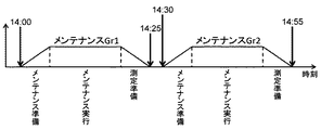
図8及び図9は、メンテナンス統合処理の様子を説明する図であって、図8はメンテナンス統合処理を実施した場合のメンテナンス処理の様子を示す図であり、図9はメンテナンス統合処理が実施されない場合のメンテナンス処理の様子を比較例として示す図である。図8及び図9においては、横軸に時間を、縦軸にメンテナンス処理に関係する各処理の実施状況を模式的に示している。 8 and 9 are diagrams for explaining the maintenance integration process. FIG. 8 is a diagram illustrating the maintenance process when the maintenance integration process is performed. FIG. 9 is a diagram where the maintenance integration process is not performed. It is a figure which shows the mode of the maintenance process in a case as a comparative example. 8 and 9, the horizontal axis represents time, and the vertical axis schematically represents the implementation status of each process related to the maintenance process.
図9の比較例においては、第1分析ユニットは、14:00にメンテナンスグループ「Gr.1」に定義されたメンテナンス実行条件を満たし、メンテナンス準備を実施した後、メンテナンス処理を開始し、その後、測定準備を実施して、14:25に試料の分析処理(測定)を再開している。その直後、14:30にメンテナンスグループ「Gr.2」のメンテナンス実行条件を満たし、メンテナンス準備を実施した後、再度第1分析ユニットにてメンテナンス処理を開始し、その後、測定準備を実施して、14:55に分析処理を再開している。自動メンテナンスを実行する場合には、図4におけるステップS401〜S408の処理が必要になるが、そのうち、ステップS401,S403,S405,S407,S408の処理は、対象となる分析ユニットのサンプル測定状況及び分析ユニットの種類により異なり、各処理ステップで時間を要する。そのため、1つのメンテナンスグループの自動メンテナンスを実行した直後に他のメンテナンスグループの自動メンテナンスを実行すると、ステップS401,S403,S405,S407,S408の処理を再度実行する事となり、分析ユニットがサンプル測定できない時間が延びるため、処理理能力への影響が考えられる。 In the comparative example of FIG. 9, the first analysis unit satisfies the maintenance execution condition defined in the maintenance group “Gr.1” at 14:00, performs maintenance preparation, starts maintenance processing, and then Preparation for measurement was carried out, and analysis processing (measurement) of the sample was resumed at 14:25. Immediately after that, at 14:30, the maintenance execution condition of the maintenance group “Gr.2” is satisfied and the maintenance preparation is performed. Then, the maintenance process is started again in the first analysis unit, and then the measurement preparation is performed. The analysis process is resumed at 14:55. When automatic maintenance is performed, the processing in steps S401 to S408 in FIG. 4 is required. Of these, the processing in steps S401, S403, S405, S407, and S408 includes the sample measurement status of the target analysis unit and Depending on the type of analysis unit, each processing step takes time. Therefore, if the automatic maintenance of another maintenance group is executed immediately after the automatic maintenance of one maintenance group is executed, the processing of steps S401, S403, S405, S407, and S408 will be executed again, and the analysis unit cannot measure the sample. Since time is extended, the impact on processing ability can be considered.
図8においては、メンテナンス実行条件の到達率が先行実施範囲値以上となってメンテナンス統合処理が実施されている。第1分析ユニットは、14:00にメンテナンスグループ「Gr.1」に定義されたメンテナンス実行条件を満たし、メンテナンス準備を実施した後、メンテナンス処理を開始し、その直後、14:20にメンテナンスグループ「Gr.2」のメンテナンス処理を開始し、その後、測定準備を実施して、14:40に分析処理を再開している。 In FIG. 8, the maintenance integration process is performed when the arrival rate of the maintenance execution condition is equal to or higher than the preceding execution range value. The first analysis unit satisfies the maintenance execution conditions defined in the maintenance group “Gr.1” at 14:00, performs maintenance preparation, starts the maintenance process, and immediately after that, at 14:20, the maintenance group “ Gr.2 "maintenance processing is started, and then measurement preparation is performed, and analysis processing is resumed at 14:40.
このように、ある一定範囲において複数のメンテナンスグループを統合して実行する事で、自動メンテナンスの実行に伴うメンテナンス準備及び測定準備を省略可能となり、自動メンテナンスに伴って生じる分析できない時間帯を短くすることが可能となる。 In this way, by integrating and executing multiple maintenance groups within a certain range, it is possible to omit maintenance preparations and measurement preparations accompanying the execution of automatic maintenance, and shorten the time zone that cannot be analyzed due to automatic maintenance. It becomes possible.
以上のように構成した本実施の形態の効果を説明する。 The effect of the present embodiment configured as described above will be described.
近年の検査センターなどにおける自動分析装置の運用では、装置を測定可能な状態で24時間継続運転しつつ測定対象の試料を順次投入して大量測定を行い、効率化を図る場合が多くなっている。その一方でメンテナンスは基本的に装置の停止状態で行う必要がありメンテナンスの実行中は試料の測定が行えないため、メンテナンスの実行タイミングによっては検査効率が低下してしまうことが考えられる。また、従来技術においては、サービスエンジニアを含むオペレータによるメンテナンスの起動作業が必要であるため、メンテナンスの開始時にはオペレータが対象の装置に拘束されることとなり、作業効率の低下が懸念される。 In the operation of automatic analyzers in recent inspection centers and the like, there are many cases in which mass measurement is performed by sequentially introducing samples to be measured while continuously operating the apparatus for 24 hours in a state where the apparatus can be measured. . On the other hand, the maintenance must basically be performed while the apparatus is stopped, and the sample cannot be measured while the maintenance is being performed. Therefore, the inspection efficiency may be reduced depending on the maintenance execution timing. Further, in the prior art, since a maintenance start operation by an operator including a service engineer is required, the operator is restrained by the target apparatus at the start of the maintenance, and there is a concern that work efficiency may be reduced.
これに対して本実施の形態においては、少なくとも1つのメンテナンス処理を含む複数のメンテナンスグループを定義し、分析ユニットの動作状態に関して予め定めた判定開始条件が満たされた場合に、メンテナンスグループのそれぞれについて予め定めたメンテナンス実行条件の到達率が予め定めた閾値を超えているメンテナンスグループのメンテナンス処理を実行するように構成したので、検査効率や作業効率の低下を抑制しつつメンテナンスを実施することにより、分析結果の信頼性を維持することができる。 On the other hand, in the present embodiment, a plurality of maintenance groups including at least one maintenance process is defined, and each of the maintenance groups is determined when a predetermined determination start condition regarding the operation state of the analysis unit is satisfied. Since the maintenance process of the maintenance group in which the arrival rate of the predetermined maintenance execution condition exceeds the predetermined threshold is executed, by performing maintenance while suppressing a decrease in inspection efficiency and work efficiency, The reliability of the analysis result can be maintained.
<第2の実施の形態>
本発明の第2の実施の形態を図10及び図11を参照しつつ説明する。
<Second Embodiment>
A second embodiment of the present invention will be described with reference to FIGS.
本実施の形態は、分析ユニットの稼動状況に応じてメンテナンス処理を先行実施する測定中回避処理をさらに行うものである。 In the present embodiment, an in-measurement avoidance process in which a maintenance process is performed in advance according to the operating status of the analysis unit is further performed.
図10は本実施の形態におけるメンテナンス処理を示すフローチャートであり、図11は、測定中回避処理に対応した自動メンテナンス設定画面の一例を示す図である。図中、第1の実施の形態と同様の部材には同じ符号を付し説明を省略する。 FIG. 10 is a flowchart showing the maintenance process in the present embodiment, and FIG. 11 is a view showing an example of an automatic maintenance setting screen corresponding to the avoidance process during measurement. In the figure, the same members as those in the first embodiment are denoted by the same reference numerals, and description thereof is omitted.
図11に示す自動メンテナンス設定画面1100は、制御部11の表示部19に表示され、操作部18によって自動メンテナンスに係る設定を定義・登録するものである。
An automatic
自動メンテナンス設定画面1100は、メンテナンスグループ名設定部1107、メンテナンス実行条件設定部1102、メンテナンス項目設定部1101、メンテナンススケジューリング設定部1103、登録ボタン1104、取消ボタン1105などから構成されている。
The automatic
自動メンテナンス設定画面1100では、メンテナンスグループ名として「Gr.3」を登録する場合を例示している。メンテナンス実行条件設定部1102には、メンテナンス処理が実行される条件として、分析ユニットでの測定回数5000テストが設定されている。メンテナンス項目設定部1101には、メンテナンスグループに加入されるメンテナンス項目と、実行順序と、対象となる分析ユニットとが設定されており、第1分析ユニットのエアパージがメンテナンス項目として設定されている。メンテナンススケジューリング設定部1103には、当該メンテナンスグループのメンテナンス処理を分析ユニットの稼動状況に応じてメンテナンス処理を先行実施する測定中回避処理で実行可能かどうかを設定する実行可否設定部1103aと、メンテナンス統合処理の実行条件を設定する先行実施範囲値設定部1103bとが設けられている。図11では、測定中回避処理が実行可能であり、先行実施範囲値として「95%」が設定されている場合を例示している。この場合、メンテナンス実行条件(測定テスト数:5000テスト)に対して測定テスト数が4750(=5000×0.95)テスト以上となった場合(到達率が95%以上となった場合)に測定中回避処理を実施する。
The automatic
ここで、測定中回避処理とは、各メンテナンスグループ単位で、測定中回避範囲値を定義し、定期的に各メンテナンスグループのメンテナンス実行条件の到達率と測定中回避範囲値とを比較する。そして、メンテナンス実行条件の到達率が測定中回避範囲値に達しており、かつ、該当分析ユニットがサンプル測定していない場合に、その条件をトリガとして、先行して該当メンテナンスグループのメンテナンスを自動的に実行するものである。 Here, the avoidance process during measurement defines an avoidance range value during measurement for each maintenance group, and periodically compares the arrival rate of the maintenance execution condition of each maintenance group with the avoidance range value during measurement. Then, when the arrival rate of the maintenance execution condition has reached the avoidance range value during measurement and the corresponding analysis unit is not measuring the sample, the maintenance of the corresponding maintenance group is automatically performed in advance using that condition as a trigger. To be executed.
図10に示すように、制御部11は、まず、操作部18及び表示部19によって自動メンテナンス設定画面1100で設定されたメンテナンスグループ(メンテナンスグループ名1106、メンテナンス項目1101)、メンテナンス実行条件1102、及びメンテナンススケジューリング設定1103を登録し(ステップS1001)、自動分析装置100を停止状態(スタンバイ状態)からサンプル測定が可能な状態(オペレーション状態)に移行して、試料の分析処理などのオペレーションを開始する(ステップS1002)。続いて、ステップS1001で登録した自動メンテナンス設定のそれぞれについてメンテナンス実行条件に係る情報を自動分析装置100の各部から取得して監視し(ステップS1003)、メンテナンス実行条件が成立したかどうかを判定する(ステップS1004)。ステップS1004での判定結果がYESの場合には、自動メンテナンス処理を実行し(ステップS1008)、処理を終了する。また、ステップS1004での判定結果がNOの場合には、測定中回避処理が実施可能であって、かつ、メンテナンス実行条件の到達率が測定中回避囲値以上となっているかどうかを判定し(ステップ1006)、対象の分析ユニットが分析処理中であってサンプル測定しているかどうかを判定する(ステップS1007)。ステップS1006及びステップS1007の判定結果がともにYESの場合には、自動メンテナンス処理を実行し(ステップS1008)、処理を終了する。また、ステップS1006及びステップS1007の判定結果の少なくとも一つがNOの場合には、ステップS1004の処理に戻る。
As shown in FIG. 10, the control unit 11 first has a maintenance group (
その他の構成は第1の実施の形態と同様である。 Other configurations are the same as those of the first embodiment.
以上のように構成した本実施の形態においても第1の実施の形態と同様の効果を得ることができる。 In the present embodiment configured as described above, the same effects as those of the first embodiment can be obtained.
<第3の実施の形態>
本発明の第3の実施の形態を図12及び図13を参照しつつ説明する。
<Third Embodiment>
A third embodiment of the present invention will be described with reference to FIGS.
本実施の形態は、第1及び第2に実施の形態において、分析ユニットの稼動状況に応じてメンテナンス処理を分割実施する処理をさらに行うものである。 In the first and second embodiments, the present embodiment further performs a process of dividing the maintenance process according to the operating status of the analysis unit.
図12は本実施の形態におけるメンテナンス処理を示すフローチャートであり、図13は、測定中回避処理に対応した自動メンテナンス設定画面の一例を示す図である。図中、第1及び第2の実施の形態と同様の部材には同じ符号を付し説明を省略する。 FIG. 12 is a flowchart showing the maintenance process in the present embodiment, and FIG. 13 is a diagram showing an example of an automatic maintenance setting screen corresponding to the avoidance process during measurement. In the figure, members similar to those in the first and second embodiments are denoted by the same reference numerals, and description thereof is omitted.
図13に示す自動メンテナンス設定画面1300は、制御部11の表示部19に表示され、操作部18によって自動メンテナンスに係る設定を定義・登録するものである。自動メンテナンス設定画面1300は、メンテナンスグループ名設定部1305、メンテナンス実行条件設定部1302、メンテナンス項目設定部1301、登録ボタン1303、取消ボタン1304などから構成されている。
An automatic
自動メンテナンス設定画面1300では、メンテナンスグループ名として「Gr.4」を登録する場合を例示している。メンテナンス実行条件設定部1302には、メンテナンス処理が実行される条件として、分析ユニットでの測定回数5000テストが設定されている。メンテナンス項目設定部1301には、メンテナンスグループに加入されるメンテナンス項目、実行順序、及び対象となる分析ユニットのほかに、スタンバイのみ実行設定部1301aが設定されており、第1分析ユニットのエアパージ、試薬プローブ洗浄、反応槽水交換、セルブランク測定、及び、光度計チェックの順にメンテナンス項目として設定されている。また、反応槽水交換、セルブランク測定、及び、光度計チェックについては、スタンバイのみ実行の設定がなされている。
The automatic
図12に示すように、制御部11は、まず、操作部18及び表示部19によって自動メンテナンス設定画面1300で設定されたメンテナンスグループ(メンテナンスグループ名1305、メンテナンス項目1301)、メンテナンス実行条件1302を登録し(ステップS1201)、自動分析装置100を停止状態(スタンバイ状態)からサンプル測定が可能な状態(オペレーション状態)に移行して、試料の分析処理などのオペレーションを開始する(ステップS1202)。続いて、ステップS1201で登録した自動メンテナンス設定のそれぞれについてメンテナンス実行条件に係る情報を自動分析装置100の各部から取得して監視し(ステップS1203)、メンテナンス実行条件が成立したかどうかを判定する(ステップS1204)。ステップS1204での判定結果がNOの場合、すなわち、メンテナンス実行条件が成立していない間は、ステップS1203を繰り返し、メンテナンス実行条件の監視を続ける。また、ステップS1204での判定結果がYESの場合には、メンテナンス実行対象の分析ユニットスタンバイ以外であるかどうかを判定する(ステップS1205)。ステップS1205での判定結果がYESの場合には、スタンバイのみ実行の設定以外のメンテナンス項目(本実施の形態では、サンプルプローブ洗浄及び試薬プローブ洗浄)をメンテナンス処理の実行対象とするとともに(ステップS1206)、スタンバイのみ実行の設定がなされたメンテナンス項目(本実施の形態では、反応槽水交換、セルブランク測定及び光度計チェック)を実行予約し(ステップS1207)、ステップS1206で実行対象としたメンテナンス項目についてのみ自動メンテナンス処理を実行する(ステップS1209)。また、ステップS1205での判定結果がNOの場合には、当該メンテナンスグループに登録されている全てのメンテナンス項目を実行対象とし(ステップS1208)、実行対象としたメンテナンス項目について自動メンテナンスを実行する(ステップS1209)。ステップS1209での自動メンテナンスを実行した後、対象の分析ユニット(本実施の形態では第1分析ユニット)の状態監視を行い(ステップS1210)、対象の分析ユニットがスタンバイ状態となったかどうかを判定し(ステップS1211)、判定結果がYESになるまでステップS1210の状態監視を継続する。ステップS1211での判定結果がYESの場合には、ステップS1207で実行予約したメンテナンス項目について自動メンテナンス処理を実行し(ステップS1212)、処理を終了する。
As shown in FIG. 12, the control unit 11 first registers the maintenance group (
その他の構成は第1及び第2の実施の形態と同様である。 Other configurations are the same as those of the first and second embodiments.
以上のように構成した本実施の形態においても第1及び第2の実施の形態と同様の効果を得ることができる。 In the present embodiment configured as described above, the same effects as those of the first and second embodiments can be obtained.
また、装置運用によっては、特定のメンテナンスは、スタンバイ状態で実行し、オペレータがメンテナンス実行による効果及び影響を確認するケースが考えられる。しかし、オペレータの負担低減の為に、自動でメンテナンスは実行したい。つまり、上記運用では、自動でメンテナンスを実行したいが、スタンバイ状態以外では実行したくないケースが想定される。そこで、本実施の形態のように、メンテナンスグループに登録する各メンテナンスに対してスタンバイのみ実行メンテナンスを設定可能とする。これにより、メンテナンス実行条件を満たして自動メンテナンスを実行する際、スタンバイのみ実行に設定されたメンテナンス項目は、実行対象分析ユニットがスタンバイ状態でない場合には、メンテナンス予約のみとして実行せず、実行対象分析ユニットがスタンバイ状態になる時に、予約したメンテナンスを自動的に実行するようにすることが可能となる。したがって、メンテナンスグループに登録したメンテナンス項目においても装置状況に合わせて分割して自動メンテナンスを実行する事で、オペレータの運用に合わせたメンテナンス処理の実行が可能になり、検査効率や作業効率の低下をさらに抑制することができる。 Further, depending on the operation of the apparatus, there may be a case where specific maintenance is performed in a standby state and the operator confirms the effect and influence of the maintenance execution. However, I want to perform maintenance automatically to reduce the burden on the operator. That is, in the above operation, there may be a case where it is desired to perform maintenance automatically but not to perform it except in the standby state. Therefore, as in the present embodiment, it is possible to set execution maintenance only for standby for each maintenance registered in the maintenance group. As a result, when the maintenance execution condition is satisfied and automatic maintenance is executed, the maintenance items set to execute only on standby are not executed as maintenance reservations only when the execution target analysis unit is not in the standby state. When the unit enters the standby state, it becomes possible to automatically execute the reserved maintenance. Therefore, even for maintenance items registered in the maintenance group, by performing automatic maintenance by dividing them according to the device status, it is possible to execute maintenance processing according to the operation of the operator, and to reduce inspection efficiency and work efficiency. Further suppression can be achieved.
<第4の実施の形態>
本発明の第4の実施の形態を図14及び図15を参照しつつ説明する。
<Fourth embodiment>
A fourth embodiment of the present invention will be described with reference to FIGS.
本実施の形態は、第1及び第2に実施の形態において、複数のメンテナンスグループに登録するメンテナンス項目の実行対象として異なる分析ユニットを指定する場合に、メンテナンス処理を複数の分析ユニットで同時に行わないようにするものである。 In this embodiment, in the first and second embodiments, when different analysis units are specified as execution targets of maintenance items registered in a plurality of maintenance groups, the maintenance process is not performed simultaneously in the plurality of analysis units. It is what you want to do.
図14は、本実施の形態における自動メンテナンス設定画面のメンテナンス項目設定部1401を抜き出して示す図であり、図15は本実施の形態におけるメンテナンス処理を示すフローチャートである。図中、第1及び第2の実施の形態と同様の部材には同じ符号を付し説明を省略する。
FIG. 14 is a diagram showing a maintenance
図14に示すように、本実施の形態では複数のメンテナンスグループが登録されている場合を例示する。図14に示すメンテナンス項目設定部1401では、メンテナンスグループ「Gr.5」は、第1分析ユニットをメンテナンス処理の対象とし、サンプルプローブ洗浄、試薬プローブの順でメンテナンス項目が登録されている。また、メンテナンス実行条件としては、対象の分析ユニットの測定テスト数2000テストが定義されている。また、メンテナンスグループ「Gr.6」は、第2分析ユニットを対象とし、メンテナンス項目として光度計チェックが登録されている。また、メンテナンス実行条件としては、対象の分析ユニットの測定テスト数2000テストが定義されている。
As shown in FIG. 14, the present embodiment exemplifies a case where a plurality of maintenance groups are registered. In the maintenance
本実施の形態では、一度に自動メンテナンスを実施する分析ユニットは1つまでとし、1つの分析ユニットの自動メンテナンスが完了したら、待機させていた他の分析ユニットの自動メンテナンスを実行することにより、作業効率の低下を抑制する。 In this embodiment, the number of analysis units that perform automatic maintenance at one time is limited to one, and when the automatic maintenance of one analysis unit is completed, the automatic maintenance of other analysis units that have been waiting is performed. Reduces efficiency.
図13において、制御部11は、まず、予め登録された自動メンテナンス設定のそれぞれについてメンテナンス実行条件に係る情報を自動分析装置100の各部から取得して監視し(ステップS1501)、メンテナンス実行条件が成立したかどうかを判定する(ステップS1502)。ステップS1502の判定結果がNOの場合、すなわち、メンテナンス実行条件が成立していない間は、ステップS1501の処理を繰り返し、メンテナンス実行条件の監視を続ける。また、ステップS1502での判定結果がYESの場合には、自動メンテナンスが実行中の分析ユニットがあるかどうかを判定し(ステップS1503)、判定結果がNOの場合には、ステップS1502でメンテナンス実行条件が成立したと判定されたメンテナンスグループについて自動メンテナンスを実行し(ステップS1505)、処理を終了する。また、ステップS1503での判定結果がYESの場合には、対象の分析ユニットの自動メンテナンスの実行予約を行う(ステップS1506)。続いて、自動メンテナンスの実施状況の監視を行い(ステップS1306)、自動メンテナンスを実行している分析ユニットがあるかどうかを判定し(ステップS1307)、判定結果がYESになるまでステップS1306の処理を繰り返して自動メンテナンスの実施状況を監視する。また、ステップS1307での判定結果がNOの場合には、ステップS1506で実行予約したメンテナンスグループ(本実施の形態では第2分析ユニットのメンテナンス項目を有するメンテナンスグループ)について自動メンテナンス(光度計チェック)を実行し(ステップS1508)、処理を終了する。
In FIG. 13, the control unit 11 first acquires and monitors information related to maintenance execution conditions from each unit of the
その他の構成は第1及び第2の実施の形態と同様である。 Other configurations are the same as those of the first and second embodiments.
以上のように構成した本実施の形態においても第1及び第2の実施の形態と同様の効果を得ることができる。 In the present embodiment configured as described above, the same effects as those of the first and second embodiments can be obtained.
また、複数のメンテナンスグループが登録されている場合に、任意のメンテナンスグループのメンテナンス実行条件が達成されて自動メンテナンスが実行されるタイミングにおいて、他の分析ユニットが自動メンテナンスを実行しているケースが発生した場合には、複数の分析ユニットにて同時に自動メンテナンスを行う事となり、サンプル測定不可である分析ユニットが複数存在して、処理能力の大幅な低下を招く事になる。これに対して本実施の形態においては、一度に自動メンテナンスを実施する分析ユニットは1つまでとし、1つの分析ユニットの自動メンテナンスが完了したら、待機させていた他の分析ユニットの自動メンテナンスを実行することにより、作業効率の低下を抑制する。 In addition, when multiple maintenance groups are registered, there is a case where another analysis unit is performing automatic maintenance at the timing when the maintenance execution condition of any maintenance group is achieved and automatic maintenance is performed. In such a case, automatic maintenance is simultaneously performed in a plurality of analysis units, and there are a plurality of analysis units incapable of measuring samples, resulting in a significant decrease in processing capacity. On the other hand, in this embodiment, only one analysis unit performs automatic maintenance at a time, and when automatic maintenance of one analysis unit is completed, automatic maintenance of other analysis units that have been waiting is performed. By doing so, a decrease in work efficiency is suppressed.
<第5の実施の形態>
本発明の第5の実施の形態を図16及び図17を参照しつつ説明する。
<Fifth embodiment>
A fifth embodiment of the present invention will be described with reference to FIGS.
本実施の形態は、第1及び第2に実施の形態において、1つのメンテナンスグループに登録するメンテナンス項目の実行対象として複数の分析ユニットを指定する場合に、メンテナンス処理を複数の分析ユニットで同時に行わないようにするものである。 In this embodiment, in the first and second embodiments, when a plurality of analysis units are specified as execution targets of maintenance items registered in one maintenance group, the maintenance process is simultaneously performed in the plurality of analysis units. It is something to prevent.
図16は、本実施の形態における自動メンテナンス設定画面のメンテナンス項目設定部1601を抜き出して示す図であり、図17は本実施の形態におけるメンテナンス処理を示すフローチャートである。図中、第1及び第2の実施の形態と同様の部材には同じ符号を付し説明を省略する。
FIG. 16 is a diagram showing an extracted maintenance
図16に示すように、本実施の形態では1つのメンテナンスグループが登録されている場合を例示する。図16に示すメンテナンス項目設定部1601では、メンテナンスグループ「Gr.7」は、第1及び第2分析ユニットをメンテナンス処理の対象とし、エアパージがメンテナンス項目として登録されている。また、メンテナンス実行条件としては、対象の分析ユニットの装置連続通電時間が50時間で定義されている。
As shown in FIG. 16, the present embodiment exemplifies a case where one maintenance group is registered. In the maintenance
本実施の形態においても、第4の実施の形態と同様に、一度に自動メンテナンスを実施する分析ユニットは1つまでとし、1つの分析ユニットの自動メンテナンスが完了したら、待機させていた他の分析ユニットの自動メンテナンスを実行することにより、作業効率の低下を抑制する。 Also in the present embodiment, as in the fourth embodiment, the number of analysis units that perform automatic maintenance at one time is limited to one, and when the automatic maintenance of one analysis unit is completed, another analysis that has been placed on standby is performed. By performing automatic maintenance of the unit, the reduction in work efficiency is suppressed.
図17において、制御部11は、まず、予め登録された自動メンテナンス設定のそれぞれについてメンテナンス実行条件に係る情報を自動分析装置100の各部から取得して監視し(ステップS1701)、メンテナンス実行条件が成立したかどうかを判定する(ステップS1702)。ステップS1702の判定結果がNOの場合、すなわち、メンテナンス実行条件が成立していない間は、ステップS1701の処理を繰り返し、メンテナンス実行条件の監視を続ける。また、ステップS1702での判定結果がYESの場合には、最初に自動メンテナンスを実行する分析ユニットを決定する(ステップS1703)。第一優先としては、サンプル測定中でない分析ユニットを優先して決定する。すなわち、サンプル測定中で無い分析ユニットは、結果出力まで待つ必要が無いため、最短時間で自動メンテナンスが実行開始できるからである。また、対象分析ユニットが全てサンプル測定中の場合は、サンプル測定完了が最も早く完了する分析ユニットを優先して自動メンテナンスを実行する分析ユニットとして決定する。このように、測定完了が早い分析ユニットを優先して自動メンテナンスを実行する事で、短時間で自動メンテナンスを開始できるため、結果としてオペレーション復帰までの時間が早く、処理能力低下を抑制することができる。また、いずれの分析ユニットもサンプル測定中でない場合は、いずれの分析ユニットから自動メンテナンスを開始しても処理能力に大きさ差は発生しないため、どの分析ユニットから自動メンテナンスを開始してもよい。例えば、図1における検体ラック投入部1に近い順(つまり、分析ユニット5,6,7,8、の順)に優先して自動メンテナンスを実行する。なお、本実施の形態では、上記優先度に従って判定した結果、第1分析ユニットにて最初に自動メンテナンスを実行する事を決定したと仮定する。
In FIG. 17, the control unit 11 first acquires and monitors information related to maintenance execution conditions from each unit of the
ステップS1703で分析ユニットが決定されると、対象の分析ユニット(第1分析ユニット)の自動メンテナンス(エアパージ)を実行し(ステップS1704)、他の分析ユニットの自動メンテナンスの実行予約を行う(ステップS1705)。続いて、自動メンテナンスの実施状況を監視して(ステップS1706)、自動メンテナンスの実行中の分析ユニットがあるかどうかを判定し(ステップS1707)、判定結果がYESになるまでステップS1706の自動メンテナンスの実施状況の監視を繰り返す。また、ステップS1707での判定結果がNOの場合には、予約した自動メンテナンス(第2分析ユニットのエアパージ)を実行し(ステップS1708)、処理を終了する。 When the analysis unit is determined in step S1703, automatic maintenance (air purge) of the target analysis unit (first analysis unit) is executed (step S1704), and execution of automatic maintenance of other analysis units is reserved (step S1705). ). Subsequently, the execution status of automatic maintenance is monitored (step S1706), it is determined whether there is an analysis unit that is executing automatic maintenance (step S1707), and the automatic maintenance in step S1706 is performed until the determination result is YES. Repeat implementation status monitoring. If the determination result in step S1707 is NO, the reserved automatic maintenance (air purge of the second analysis unit) is executed (step S1708), and the process ends.
その他の構成は第1及び第2の実施の形態と同様である。 Other configurations are the same as those of the first and second embodiments.
以上のように構成した本実施の形態においても第1、第2、及び第4の実施の形態と同様の効果を得ることができる。 In the present embodiment configured as described above, the same effects as those of the first, second, and fourth embodiments can be obtained.
なお、本発明は上記した各実施の形態に限定されるものではなく、様々な変形例が含まれる。例えば、上記した実施の形態は本願発明を分かりやすく説明するために詳細に説明したものであり、必ずしも説明した全ての構成を備えるものに限定されるものではない。また、上記した各実施の形態を組み合わせて実施することも可能である。 In addition, this invention is not limited to each above-mentioned embodiment, Various modifications are included. For example, the above-described embodiment has been described in detail for easy understanding of the present invention, and is not necessarily limited to one having all the configurations described. It is also possible to implement a combination of the above embodiments.
1 検体ラック投入部
2 読取部
3 検体ラック搬送ライン
4 再検査用搬送ライン
5〜8 分析ユニット
9 検体ラック待機部
10 検体ラック回収部
11 制御部
12〜17 制御用コンピュータ
18 操作部
19 表示部
51,61,71,81 検体ラック引込線
100 自動分析装置
300,600,700,1100,1300 自動メンテナンス設定画面
DESCRIPTION OF
Claims (6)
前記検体ラック搬送ラインに沿って配置され、少なくとも、試料を反応容器に分注する試料分注機構、試薬を前記反応容器に分注する試薬分注機構、及び前記反応容器に収容された試料と試薬の混合液を測定する測定機構を含む複数の分析要素によって分析処理を行う1つ以上の分析ユニットと、
前記分析ユニットを構成する複数の分析要素のメンテナンス処理について、少なくとも1つのメンテナンス処理を含む複数のメンテナンスグループを定義し、前記分析ユニットの動作状態に関して予め定めた判定開始条件が満たされた場合に、前記メンテナンスグループのそれぞれについて予め定めたメンテナンス実行条件の到達率が予め定めた閾値を超えているメンテナンスグループのメンテナンス処理を実行する制御部と
を備えたことを特徴とする自動分析装置。 A sample rack transport line for transporting the sample rack between a sample rack loading unit and a sample rack collection unit for loading a sample rack loaded with one or more sample containers containing samples to be analyzed;
A sample dispensing mechanism that is disposed along the sample rack transport line and dispenses at least a sample into a reaction container; a reagent dispensing mechanism that dispenses a reagent into the reaction container; and a sample contained in the reaction container; One or more analysis units for performing an analysis process by a plurality of analysis elements including a measurement mechanism for measuring a mixture of reagents;
For a maintenance process of a plurality of analysis elements constituting the analysis unit, a plurality of maintenance groups including at least one maintenance process is defined, and when a predetermined determination start condition regarding the operation state of the analysis unit is satisfied, An automatic analyzer comprising: a control unit that executes maintenance processing of a maintenance group in which an arrival rate of a predetermined maintenance execution condition exceeds a predetermined threshold for each of the maintenance groups.
前記判定開始条件は、他のメンテナンスグループのメンテナンス実行条件の到達率が100%以上であることを特徴とする自動分析装置。 The automatic analyzer according to claim 1, wherein
The automatic analysis apparatus according to claim 1, wherein the determination start condition is that an arrival rate of maintenance execution conditions of other maintenance groups is 100% or more.
前記判定開始条件は、前記メンテナンスグループに属するメンテナンス処理の対象となる分析ユニットにおける分析処理が行われていない状態であることを特徴とする自動分析装置。 The automatic analyzer according to claim 1, wherein
The automatic analysis apparatus according to claim 1, wherein the determination start condition is a state in which an analysis process is not performed in an analysis unit that is a maintenance process target belonging to the maintenance group.
前記分析ユニットがスタンバイ状態の場合のみメンテナンス処理を実行する前記メンテナンスグループ又は各メンテナンス処理を設定することができるスタンバイ時実行設定部を備えたことを特徴とする自動分析装置。 The automatic analyzer according to claim 1, wherein
An automatic analyzer comprising a standby execution setting unit capable of setting the maintenance group or each maintenance process that executes a maintenance process only when the analysis unit is in a standby state.
前記メンテナンスグループ、前記判定開始条件、及び閾値を設定する条件設定部を備えたことを特徴とする自動分析装置。 The automatic analyzer according to claim 1, wherein
An automatic analyzer comprising a condition setting unit for setting the maintenance group, the determination start condition, and a threshold value.
複数の分析ユニットのメンテナンスが同時に実行される条件を満たした場合には、少なくとも1つの分析ユニットのメンテナンスの開始を他の分析ユニットのメンテナンスの終了後まで延期することを特徴とする自動分析装置。 The automatic analyzer according to claim 1, wherein
An automatic analyzer characterized by deferring the start of maintenance of at least one analysis unit until the end of maintenance of other analysis units when a condition for performing maintenance of a plurality of analysis units simultaneously is satisfied.
Priority Applications (1)
| Application Number | Priority Date | Filing Date | Title |
|---|---|---|---|
| JP2016029991A JP6719227B2 (en) | 2016-02-19 | 2016-02-19 | Automatic analyzer |
Applications Claiming Priority (1)
| Application Number | Priority Date | Filing Date | Title |
|---|---|---|---|
| JP2016029991A JP6719227B2 (en) | 2016-02-19 | 2016-02-19 | Automatic analyzer |
Publications (2)
| Publication Number | Publication Date |
|---|---|
| JP2017146264A true JP2017146264A (en) | 2017-08-24 |
| JP6719227B2 JP6719227B2 (en) | 2020-07-08 |
Family
ID=59683067
Family Applications (1)
| Application Number | Title | Priority Date | Filing Date |
|---|---|---|---|
| JP2016029991A Active JP6719227B2 (en) | 2016-02-19 | 2016-02-19 | Automatic analyzer |
Country Status (1)
| Country | Link |
|---|---|
| JP (1) | JP6719227B2 (en) |
Cited By (3)
| Publication number | Priority date | Publication date | Assignee | Title |
|---|---|---|---|---|
| WO2019189869A1 (en) * | 2018-03-29 | 2019-10-03 | 株式会社日立ハイテクノロジーズ | Automated analysis system |
| CN112578139A (en) * | 2019-09-30 | 2021-03-30 | 深圳迈瑞生物医疗电子股份有限公司 | Sample testing method, sample analyzer and storage medium |
| WO2022185788A1 (en) * | 2021-03-03 | 2022-09-09 | 株式会社日立ハイテク | Automatic analysis system and specimen distribution method |
Citations (4)
| Publication number | Priority date | Publication date | Assignee | Title |
|---|---|---|---|---|
| JP2004271265A (en) * | 2003-03-06 | 2004-09-30 | Hitachi High-Technologies Corp | Automatic analyzer |
| JP2011149747A (en) * | 2010-01-20 | 2011-08-04 | Hitachi High-Technologies Corp | Autoanalyzer |
| WO2012120755A1 (en) * | 2011-03-04 | 2012-09-13 | 株式会社 日立ハイテクノロジーズ | Analysis device |
| WO2017033597A1 (en) * | 2015-08-26 | 2017-03-02 | 株式会社日立ハイテクノロジーズ | Automatic analysis device |
-
2016
- 2016-02-19 JP JP2016029991A patent/JP6719227B2/en active Active
Patent Citations (5)
| Publication number | Priority date | Publication date | Assignee | Title |
|---|---|---|---|---|
| JP2004271265A (en) * | 2003-03-06 | 2004-09-30 | Hitachi High-Technologies Corp | Automatic analyzer |
| JP2011149747A (en) * | 2010-01-20 | 2011-08-04 | Hitachi High-Technologies Corp | Autoanalyzer |
| WO2012120755A1 (en) * | 2011-03-04 | 2012-09-13 | 株式会社 日立ハイテクノロジーズ | Analysis device |
| JP2015108641A (en) * | 2011-03-04 | 2015-06-11 | 株式会社日立ハイテクノロジーズ | Clinical examination analysis device |
| WO2017033597A1 (en) * | 2015-08-26 | 2017-03-02 | 株式会社日立ハイテクノロジーズ | Automatic analysis device |
Cited By (8)
| Publication number | Priority date | Publication date | Assignee | Title |
|---|---|---|---|---|
| WO2019189869A1 (en) * | 2018-03-29 | 2019-10-03 | 株式会社日立ハイテクノロジーズ | Automated analysis system |
| CN111108391A (en) * | 2018-03-29 | 2020-05-05 | 株式会社日立高新技术 | Automatic analysis system |
| JPWO2019189869A1 (en) * | 2018-03-29 | 2020-10-22 | 株式会社日立ハイテク | Automatic analysis system |
| US10962559B2 (en) | 2018-03-29 | 2021-03-30 | Hitachi High-Tech Corporation | Automated analysis system |
| CN111108391B (en) * | 2018-03-29 | 2021-06-29 | 株式会社日立高新技术 | Automatic analysis system |
| CN112578139A (en) * | 2019-09-30 | 2021-03-30 | 深圳迈瑞生物医疗电子股份有限公司 | Sample testing method, sample analyzer and storage medium |
| CN112578139B (en) * | 2019-09-30 | 2024-04-05 | 深圳迈瑞生物医疗电子股份有限公司 | Sample testing method, sample analyzer and storage medium |
| WO2022185788A1 (en) * | 2021-03-03 | 2022-09-09 | 株式会社日立ハイテク | Automatic analysis system and specimen distribution method |
Also Published As
| Publication number | Publication date |
|---|---|
| JP6719227B2 (en) | 2020-07-08 |
Similar Documents
| Publication | Publication Date | Title |
|---|---|---|
| JP4906431B2 (en) | Automatic analyzer | |
| JP5872287B2 (en) | Automatic analyzer | |
| JP6307446B2 (en) | Centrifuge system, specimen pretreatment system, and control method | |
| JP6696045B2 (en) | Automatic analyzer | |
| JP2019066487A (en) | Autoanalysis device | |
| JP6498201B2 (en) | Automatic analyzer | |
| JP2008209338A (en) | Automatic analyzer | |
| WO2010073502A1 (en) | Automatic analysis device | |
| CN214622684U (en) | Automatic sample introduction device | |
| JP6719227B2 (en) | Automatic analyzer | |
| KR20190082678A (en) | System and method for laboratory screening of biological samples | |
| JP2006038881A (en) | Automatic analyzing system of biological sample | |
| EP3588093A1 (en) | Automated analyzer | |
| JP6913232B2 (en) | Automatic analysis system | |
| EP3415920A1 (en) | Automatic analysis device | |
| JP6426569B2 (en) | Sample inspection system | |
| JP5174629B2 (en) | Automatic analyzer | |
| JP6710558B2 (en) | Sample transport system and sample inspection system | |
| JP2016156675A (en) | Automatic analysis device and analysis method | |
| CN114008459A (en) | Automatic sample introduction system, sample analysis system and automatic sample introduction control method | |
| JP6210891B2 (en) | Automatic analyzer | |
| JPH11258248A (en) | Method and apparatus for transferring specimen | |
| JP2005241612A (en) | Automatic analysis system | |
| WO2015112798A1 (en) | Priority indicator for automation system fluid sample | |
| WO2020162042A1 (en) | Automatic analysis device |
Legal Events
| Date | Code | Title | Description |
|---|---|---|---|
| A621 | Written request for application examination |
Free format text: JAPANESE INTERMEDIATE CODE: A621 Effective date: 20181212 |
|
| A977 | Report on retrieval |
Free format text: JAPANESE INTERMEDIATE CODE: A971007 Effective date: 20191213 |
|
| A131 | Notification of reasons for refusal |
Free format text: JAPANESE INTERMEDIATE CODE: A131 Effective date: 20191224 |
|
| A521 | Request for written amendment filed |
Free format text: JAPANESE INTERMEDIATE CODE: A523 Effective date: 20200221 |
|
| TRDD | Decision of grant or rejection written | ||
| A01 | Written decision to grant a patent or to grant a registration (utility model) |
Free format text: JAPANESE INTERMEDIATE CODE: A01 Effective date: 20200526 |
|
| A61 | First payment of annual fees (during grant procedure) |
Free format text: JAPANESE INTERMEDIATE CODE: A61 Effective date: 20200616 |
|
| R150 | Certificate of patent or registration of utility model |
Ref document number: 6719227 Country of ref document: JP Free format text: JAPANESE INTERMEDIATE CODE: R150 |