JP2017143141A - Single-wafer cleaning apparatus and wafer cleaning method - Google Patents
Single-wafer cleaning apparatus and wafer cleaning method Download PDFInfo
- Publication number
- JP2017143141A JP2017143141A JP2016022872A JP2016022872A JP2017143141A JP 2017143141 A JP2017143141 A JP 2017143141A JP 2016022872 A JP2016022872 A JP 2016022872A JP 2016022872 A JP2016022872 A JP 2016022872A JP 2017143141 A JP2017143141 A JP 2017143141A
- Authority
- JP
- Japan
- Prior art keywords
- wafer
- chamber
- anemometer
- wind speed
- cleaning
- Prior art date
- Legal status (The legal status is an assumption and is not a legal conclusion. Google has not performed a legal analysis and makes no representation as to the accuracy of the status listed.)
- Granted
Links
- 238000004140 cleaning Methods 0.000 title claims abstract description 89
- 238000000034 method Methods 0.000 title claims description 17
- 239000000126 substance Substances 0.000 claims abstract description 35
- 238000005259 measurement Methods 0.000 claims description 18
- 230000007547 defect Effects 0.000 abstract description 38
- 239000003595 mist Substances 0.000 abstract description 16
- 239000007788 liquid Substances 0.000 abstract description 6
- 235000012431 wafers Nutrition 0.000 description 148
- 239000000243 solution Substances 0.000 description 17
- XUIMIQQOPSSXEZ-UHFFFAOYSA-N Silicon Chemical compound [Si] XUIMIQQOPSSXEZ-UHFFFAOYSA-N 0.000 description 14
- 229910052710 silicon Inorganic materials 0.000 description 14
- 239000010703 silicon Substances 0.000 description 14
- XLYOFNOQVPJJNP-UHFFFAOYSA-N water Substances O XLYOFNOQVPJJNP-UHFFFAOYSA-N 0.000 description 10
- KRHYYFGTRYWZRS-UHFFFAOYSA-N Fluorane Chemical compound F KRHYYFGTRYWZRS-UHFFFAOYSA-N 0.000 description 6
- CBENFWSGALASAD-UHFFFAOYSA-N Ozone Chemical compound [O-][O+]=O CBENFWSGALASAD-UHFFFAOYSA-N 0.000 description 5
- 230000000052 comparative effect Effects 0.000 description 5
- 238000011109 contamination Methods 0.000 description 5
- 238000003672 processing method Methods 0.000 description 5
- 230000000694 effects Effects 0.000 description 3
- 238000005530 etching Methods 0.000 description 2
- 238000004519 manufacturing process Methods 0.000 description 2
- 239000008155 medical solution Substances 0.000 description 2
- 239000002245 particle Substances 0.000 description 2
- 239000004065 semiconductor Substances 0.000 description 2
- 238000005406 washing Methods 0.000 description 2
- 230000003247 decreasing effect Effects 0.000 description 1
- 238000001514 detection method Methods 0.000 description 1
- 230000006866 deterioration Effects 0.000 description 1
- 238000001035 drying Methods 0.000 description 1
- 238000011086 high cleaning Methods 0.000 description 1
- 230000002401 inhibitory effect Effects 0.000 description 1
- 230000002093 peripheral effect Effects 0.000 description 1
- 230000003746 surface roughness Effects 0.000 description 1
Images

Classifications
-
- H—ELECTRICITY
- H01—ELECTRIC ELEMENTS
- H01L—SEMICONDUCTOR DEVICES NOT COVERED BY CLASS H10
- H01L21/00—Processes or apparatus adapted for the manufacture or treatment of semiconductor or solid state devices or of parts thereof
- H01L21/02—Manufacture or treatment of semiconductor devices or of parts thereof
- H01L21/04—Manufacture or treatment of semiconductor devices or of parts thereof the devices having at least one potential-jump barrier or surface barrier, e.g. PN junction, depletion layer or carrier concentration layer
- H01L21/18—Manufacture or treatment of semiconductor devices or of parts thereof the devices having at least one potential-jump barrier or surface barrier, e.g. PN junction, depletion layer or carrier concentration layer the devices having semiconductor bodies comprising elements of Group IV of the Periodic System or AIIIBV compounds with or without impurities, e.g. doping materials
- H01L21/30—Treatment of semiconductor bodies using processes or apparatus not provided for in groups H01L21/20 - H01L21/26
- H01L21/302—Treatment of semiconductor bodies using processes or apparatus not provided for in groups H01L21/20 - H01L21/26 to change their surface-physical characteristics or shape, e.g. etching, polishing, cutting
- H01L21/304—Mechanical treatment, e.g. grinding, polishing, cutting
Landscapes
- Engineering & Computer Science (AREA)
- Physics & Mathematics (AREA)
- Condensed Matter Physics & Semiconductors (AREA)
- General Physics & Mathematics (AREA)
- Manufacturing & Machinery (AREA)
- Computer Hardware Design (AREA)
- Microelectronics & Electronic Packaging (AREA)
- Power Engineering (AREA)
- Cleaning Or Drying Semiconductors (AREA)
- Container, Conveyance, Adherence, Positioning, Of Wafer (AREA)
Abstract
Description
本発明は、枚葉式ウェーハ洗浄処理装置及びウェーハ洗浄処理方法に関する。 The present invention relates to a single wafer cleaning apparatus and a wafer cleaning method.
半導体ウェーハ等のウェーハを洗浄する装置としては、複数枚のウェーハを薬液が充填された薬液槽に浸漬して洗浄するバッチ方式の洗浄処理装置と、1枚のウェーハを回転させ、そのウェーハに対して薬液を噴射して洗浄する枚葉方式の洗浄処理装置がある。近年では、半導体デバイスの微細化やウェーハの大型化にともない、洗浄効果の高い枚葉方式の洗浄処理装置が用いられる傾向にある(特許文献1)。 As a device for cleaning a wafer such as a semiconductor wafer, a batch type cleaning processing device for cleaning by immersing a plurality of wafers in a chemical bath filled with a chemical solution, and rotating one wafer with respect to the wafer. In addition, there is a single-wafer type cleaning apparatus that injects a chemical solution for cleaning. In recent years, with the miniaturization of semiconductor devices and the increase in size of wafers, single wafer cleaning apparatuses having a high cleaning effect tend to be used (Patent Document 1).
枚葉方式の洗浄処理装置として、チャンバーと呼ばれる洗浄処理装置筐体と、チャンバーの上部に設けられエアーを給気する給気部と、チャンバーの下部に設けられ排気を行う排気部と、ウェーハを保持し回転させるテーブル部と、ウェーハ上に薬液を供給するノズル部と、飛散した薬液を回収又は排液するためのカップ部で構成される枚葉式洗浄処理装置が知られている。
As a single wafer type cleaning processing apparatus, a cleaning processing device casing called a chamber, an air supply part provided at the upper part of the chamber for supplying air, an exhaust part provided at the lower part of the chamber for exhausting air, and a
このような従来の枚葉式洗浄処理装置においては、給気部と排気部の風速や風量を計測(監視)し、それらのバランスを調整することによって洗浄処理装置内部の圧力を制御している。 In such a conventional single wafer cleaning processing apparatus, the air speed and the air volume of the air supply section and the exhaust section are measured (monitored), and the pressure inside the cleaning processing apparatus is controlled by adjusting the balance between them. .
このような枚葉式洗浄処理装置を使用した場合の問題について本発明者らは鋭意研究を行い、以下のことを見出した。ウェーハの洗浄を行うにあたり最も問題となるのが、回転しているウェーハへ吐出した薬液が飛散した際に起きるカップ部からの跳ね返りや、ウェーハとテーブル部が回転する際にウェーハの端部で発生する乱流により薬液のミストがウェーハ上へ付着し、ウェーハを汚染することである。飛散した薬液の跳ね返りやミストにより薬液がウェーハに付着すれば、単にウェーハ表面を汚染するだけでなく、ウェーハ表面の表面粗さを悪化させる要因やエッチング等の原因ともなる。また、純水やオゾン水などがウェーハに付着するとウォーターマークの原因となる。 The inventors of the present invention conducted intensive research on the problems in the case of using such a single wafer cleaning apparatus, and found the following. The most serious problem when cleaning wafers is that the chemicals discharged to the rotating wafer bounce off the cup, and occur at the edge of the wafer when the wafer and table rotate. The turbulent flow causes chemical mist to adhere to the wafer and contaminate the wafer. If the chemical solution adheres to the wafer due to splashing of the scattered chemical solution or mist, it not only contaminates the wafer surface but also causes deterioration of the surface roughness of the wafer surface and causes of etching. Further, if pure water or ozone water adheres to the wafer, it causes a watermark.
従来の枚葉式洗浄処理装置では、給気部や排気部での風量や風速を制御しているが、それは装置内部の圧力を制御するためであり、ウェーハ端で発生する乱流の制御は行っていない。 In the conventional single wafer cleaning processing equipment, the air volume and air speed at the air supply section and exhaust section are controlled. This is to control the pressure inside the equipment. not going.
このウェーハ端で発生する乱流が制御されていないと、給気部や排気部での風速や風量を制御しても、結局、ウェーハとテーブル部の回転中に供給された薬液が飛散した際にカップ部にあたりミストとなったものがウェーハ上に付着し、パーティクル、ウォーターマーク、エッチング等の汚染源となってしまっていた。 If the turbulent flow generated at the wafer edge is not controlled, even if the air speed and air volume at the air supply and exhaust sections are controlled, the chemical solution supplied during the rotation of the wafer and table will eventually scatter. The mist that hits the cup part adhered to the wafer and became a source of contamination such as particles, watermarks, and etching.
また、この乱流を抑制するために、給気部や排気部での風速を大きく上昇させると、カップ構造と強い気流による渦が発生し、ミストの巻き戻りが発生するなどの問題が生じていた。 In order to suppress this turbulent flow, if the wind speed at the air supply section or exhaust section is greatly increased, vortices are generated due to the cup structure and strong air flow, and mist rewinding occurs. It was.
本発明は、上記問題点に鑑みてなされたものであって、枚葉式のウェーハ洗浄処理装置を用いてウェーハの洗浄を行う場合に、乱流の影響により発生する、薬液のミスト等によるウェーハ表面の欠陥を抑制することができる枚葉式ウェーハ洗浄処理装置及びウェーハ洗浄処理方法を提供することを目的とする。 The present invention has been made in view of the above-described problems, and when a wafer is cleaned using a single wafer cleaning apparatus, a wafer caused by a mist of a chemical solution generated due to the influence of turbulent flow. It is an object of the present invention to provide a single wafer cleaning apparatus and a wafer cleaning method capable of suppressing surface defects.
上記目的を達成するために、本発明は、チャンバー内に配置されたカップ部と、該カップ部内に配置され、ウェーハを保持し回転するテーブル部と、前記ウェーハに薬液を供給するノズル部とを具備する枚葉式のウェーハ洗浄処理装置であって、
前記チャンバーに設けられた給気部と、
該給気部の風量を調整する給気風量可変機構と、
前記チャンバーに設けられた排気部と、
該排気部の風量を調整する排気風量可変機構と、
前記テーブル部に保持されるウェーハの端部の位置の風速を測定する風速計とを備えるものであることを特徴とする枚葉式ウェーハ洗浄処理装置を提供する。
In order to achieve the above object, the present invention includes a cup portion disposed in a chamber, a table portion disposed in the cup portion for holding and rotating the wafer, and a nozzle portion for supplying a chemical to the wafer. A single wafer cleaning apparatus comprising:
An air supply section provided in the chamber;
A supply air volume variable mechanism for adjusting the air volume of the supply section;
An exhaust section provided in the chamber;
An exhaust air volume variable mechanism for adjusting the air volume of the exhaust part;
Provided is a single wafer cleaning apparatus characterized by comprising an anemometer for measuring an air velocity at a position of an end portion of a wafer held by the table portion.
このように、ウェーハの端部の位置の風速を測定する風速計を備える枚葉式ウェーハ洗浄処理装置であれば、回転していない時のウェーハの端部の位置の風速を測定しつつ、給気風量可変機構と排気風量可変機構により該風速を適切な値に調整することができる。そして、調整した状態でウェーハを回転させつつ洗浄処理することができる。これにより、ウェーハの端部の位置での洗浄時の乱流の発生とそれによるミスト等の巻き上がりを抑制することができ、洗浄処理する際にウェーハ表面にミスト等の付着による欠陥が発生することを防止することができる。 Thus, in the case of a single wafer type wafer cleaning processing apparatus equipped with an anemometer that measures the wind speed at the position of the wafer edge, the wind speed at the position of the edge of the wafer when not rotating is measured. The wind speed can be adjusted to an appropriate value by the air volume variable mechanism and the exhaust air volume variable mechanism. Then, the cleaning process can be performed while rotating the wafer in the adjusted state. As a result, generation of turbulent flow during cleaning at the position of the edge of the wafer and roll-up of mist due thereto can be suppressed, and defects due to adhesion of mist or the like occur on the wafer surface during cleaning processing. This can be prevented.
このとき、前記風速計は、前記ウェーハの端部の測定位置から退避可能なものであることが好ましい。 At this time, the anemometer is preferably retractable from the measurement position at the end of the wafer.
このように、風速計が退避可能であれば、ウェーハの洗浄処理を開始する前に、風速計をウェーハの端部の測定位置から退避させ、飛散した薬液が風速計に当たらないようにすることができ、風速計からの薬液の跳ね返りをより確実に防止することができる。さらに、風速計に薬液が付着し風速測定に影響を与えることをより確実に防ぐことができる。 In this way, if the anemometer can be retracted, the anemometer should be retracted from the measurement position at the edge of the wafer before starting the wafer cleaning process so that the scattered chemical does not hit the anemometer. It is possible to more reliably prevent the chemical solution from bouncing off from the anemometer. Furthermore, it can prevent more reliably that a chemical | medical solution adheres to an anemometer and influences a wind speed measurement.
このとき、前記枚葉式ウェーハ洗浄処理装置は、前記チャンバーの内外の差圧を測定する圧力計をさらに備えるものであることが好ましい。 At this time, it is preferable that the single wafer cleaning apparatus further includes a pressure gauge for measuring a differential pressure inside and outside the chamber.
このような圧力計を備えることで、チャンバーの内外の差圧を測定することができ、給気風量可変機構と排気風量可変機構を調整することによりチャンバー内の圧力をチャンバー外の圧力に比べて適切な範囲内とすることができる。すなわち、チャンバー内が過度の陰圧又は陽圧になることを防ぎ、それらを起因としてウェーハ表面に欠陥が発生することをより効果的に防止することができる。 By providing such a pressure gauge, the pressure difference inside and outside the chamber can be measured, and the pressure inside the chamber can be compared with the pressure outside the chamber by adjusting the supply air volume variable mechanism and the exhaust air volume variable mechanism. It can be within an appropriate range. That is, it is possible to prevent the inside of the chamber from becoming an excessive negative pressure or a positive pressure, and it is possible to more effectively prevent defects from occurring on the wafer surface due to them.
また、上記目的を達成するために、本発明は、チャンバー内に配置されたカップ部を有し、該カップ部内に配置されたテーブル部により保持され、回転されるウェーハに、ノズル部から薬液を供給しつつ前記ウェーハを枚葉式で洗浄処理するウェーハ洗浄処理方法であって、
前記テーブル部が回転していない時の、前記テーブル部に保持されたウェーハの端部の位置の風速を風速計により測定しつつ、該風速が1.0m/sec以上となるように、前記チャンバー内への給気の風量と前記チャンバー外への排気の風量のうち1つ以上を調整した状態で、前記テーブル部を回転させつつ前記ウェーハを洗浄処理することを特徴とするウェーハ洗浄処理方法を提供する。
In order to achieve the above object, the present invention has a cup portion arranged in a chamber, and holds a chemical solution from a nozzle portion on a wafer held and rotated by a table portion arranged in the cup portion. A wafer cleaning processing method for cleaning the wafer in a single wafer manner while supplying,
The chamber is adjusted so that the wind speed is 1.0 m / sec or more while measuring the wind speed at the position of the end of the wafer held by the table section with the anemometer when the table section is not rotating. A wafer cleaning method, wherein the wafer is cleaned while rotating the table unit in a state where at least one of an air flow rate for supplying air into the chamber and an air flow rate for exhausting the chamber outside is adjusted. provide.
このように、回転していない時のウェーハの端部の位置の風速を風速計により測定しつつ、該風速が1.0m/sec以上になるように調整することができる。そして、調整した状態でウェーハを回転させつつ洗浄処理を行えば、洗浄時の乱流の発生とそれによるミスト等の巻き上がりを抑制することができ、洗浄処理する際にウェーハ表面にミスト等が付着することによる欠陥の発生を防止することができる。 Thus, the wind speed at the position of the edge of the wafer when not rotating can be adjusted so that the wind speed is 1.0 m / sec or more while measuring the wind speed with the anemometer. If the cleaning process is performed while rotating the wafer in an adjusted state, the generation of turbulent flow during cleaning and the resulting mist roll-up can be suppressed. Generation of defects due to adhesion can be prevented.
このとき、前記風速の測定後、前記ウェーハを洗浄処理する前に、前記風速計を前記ウェーハの端部の測定位置から退避させることが好ましい。 At this time, it is preferable that the anemometer is retracted from the measurement position at the end of the wafer after the measurement of the wind speed and before cleaning the wafer.
このように、ウェーハを洗浄処理する前に風速計を測定位置から退避させることにより、飛散した薬液が風速計に当たらないようにすることができ、風速計からの薬液の跳ね返りをより確実に防止することができる。さらに、風速計に薬液が付着し風速測定に影響を与えることをより確実に防ぐことができる。 In this way, by retracting the anemometer from the measurement position before cleaning the wafer, it is possible to prevent the scattered chemical from hitting the anemometer, and more reliably preventing the chemical from splashing from the anemometer. can do. Furthermore, it can prevent more reliably that a chemical | medical solution adheres to an anemometer and influences a wind speed measurement.
このとき、前記ウェーハの端部の位置の風速を調整する際に、前記チャンバーの内外の差圧を0〜5Paの範囲内とすることが好ましい。 At this time, when adjusting the wind speed at the position of the end of the wafer, it is preferable that the pressure difference between the inside and outside of the chamber is within a range of 0 to 5 Pa.
このようにチャンバーの内外の差圧を0〜5Paの範囲内にすることで、チャンバー内が過度の陰圧や陽圧にならないようにして、陰圧又は陽圧に起因する欠陥がウェーハ表面に発生することをより効果的に防止することができる。 In this way, by setting the differential pressure inside and outside the chamber within the range of 0 to 5 Pa, the inside of the chamber does not become excessive negative pressure or positive pressure, and defects caused by the negative pressure or positive pressure are caused on the wafer surface. Generation | occurrence | production can be prevented more effectively.
以上のように、本発明の枚葉式ウェーハ洗浄処理装置及びウェーハ洗浄処理方法によれば、ウェーハの回転時にウェーハの端部で発生する乱流によるミスト等のウェーハへの付着を防止し、ミスト等によるウェーハ表面の欠陥数の増加を効果的に抑制することができる。 As described above, according to the single wafer cleaning apparatus and the wafer cleaning processing method of the present invention, it is possible to prevent the mist from adhering to the wafer due to the turbulent flow generated at the edge of the wafer when the wafer rotates. The increase in the number of defects on the wafer surface due to the above can be effectively suppressed.
以下、本発明について、実施態様の一例として、図を参照しながら詳細に説明するが、本発明はこれらに限定されるものではない。 Hereinafter, the present invention will be described in detail as an example of embodiments with reference to the drawings. However, the present invention is not limited to these.
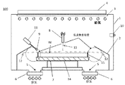
まず、本発明の枚葉式ウェーハ洗浄処理装置について、図1を参照して説明する。図1は、本発明の枚葉式ウェーハ洗浄処理装置の一例を示す概略図である。 First, a single wafer cleaning apparatus according to the present invention will be described with reference to FIG. FIG. 1 is a schematic view showing an example of a single wafer cleaning apparatus according to the present invention.
図1の枚葉式ウェーハ洗浄処理装置100は、チャンバー1と、カップ部2と、チャンバー1に設けられた給気部3と、該給気部3の風量を調整する給気風量可変機構4と、チャンバー1に設けられた排気部5と、該排気部5の風量を調整する排気風量可変機構6と、ウェーハWを保持し、回転駆動するテーブル部7と、ウェーハWに薬液13を供給するノズル部8と、テーブル部7に保持されるウェーハWの端部の位置の風速を測定する風速計9とを備えている。さらに、枚葉式ウェーハ洗浄処理装置100は、チャンバー内とチャンバー外の差圧を測定する圧力計10と、風速計9をウェーハWの端部の位置から退避させることができる機構(風速計退避機構)11とを備えていてよい。
A single
チャンバー1は、枚葉式ウェーハ洗浄処理装置100を構成する筐体であり、カップ部2、テーブル部7、及びノズル部8などを収容している。カップ部2は、チャンバー内に設けられ、ウェーハWの回転により周囲に飛散した薬液12を回収又は排液するためのものであり、ウェーハWを取り囲むように設けられている。カップ部2は、図1に示すように、上部に内側に向かって傾斜のついた部分を有しており、この傾斜のついた部分の水平との角度は、例えば、15〜30°とすることができる。
The
給気部3は、チャンバー1の上部に設けられ、例えば、温度及び湿度が制御された空気(エアー)をチャンバー1内に供給する機能を有する。しかしながら、給気部3がチャンバー1内に供給する気体は空気に限定されるものではない。給気風量可変機構4は、給気部3によりチャンバー1内に供給する気体の風量(及び/又は風速)を調整する機能を有する。給気風量可変機構4は、例えば、ファンの形態とすることができ、ファンの回転数を増減することで、風量を調整することが可能であるが、ファンの形態に限定されるものではない。
The
排気部5は、チャンバー1の下部に設けられ、チャンバー1内の排気を行う機能を有する。排気風量可変機構6は、排気部5、例えば排気部5のダクト等に設けられ、排気部5における排気の風量(及び/又は風速)を調整する機能を有する。排気風量可変機構6は、例えば、ダンパの形態とすることができ、ダンパの開閉を制御することで、排気部5の風量を調整することが可能であるが、ダンパの形態に限定されるものではない。
The
テーブル部7は、回転駆動するテーブル14と該テーブル14上に設けられた複数の保持ピン15から構成され、保持ピン15でウェーハWを外周側から保持する。ノズル部8は、ウェーハWの上方に設けられ、ウェーハWの主表面に、例えば、フッ酸等の薬液、オゾン水、及び純水等を供給する複数のノズルを有していてもよい。
The
風速計9は、風速測定位置がウェーハWの端部の位置となるように設けられる。このウェーハWの端部の位置において、ウェーハWとテーブル部7が回転する際に(洗浄時に)乱流が発生する。風速計9により、洗浄時に乱流が発生する位置においてテーブル部7が回転していない時(非洗浄時)の風速を正確に測定することができる。風速計9として、例えば、熱線式風速計を用いることができるが、これに限定されるものではない。
The
このように、風速計9を備えているので、ウェーハWの端部の位置での、非洗浄時における風速を正確に測定し、給気風量可変機構4と排気風量可変機構6により該風速を適切な値に調整することができる。ここで言う非洗浄時の適切な風速値とは、その風速の条件(給気風量や排気風量など)の下、洗浄を始めても(テーブル部7を回転させても)、ウェーハWの端部で乱流が発生しないような値を意味する。これにより、洗浄時に乱流の発生とそれによるミスト等の巻き上がり(巻き戻し)を抑制することができ、洗浄処理する際にウェーハWの表面にミスト等による欠陥が発生することを防止することができる。
Thus, since the
風速計9は、位置や高さを調整可能な構成とすることができる。また、風速計9は、風速計退避機構11により、手動又は自動で、飛散した薬液12が当たらない位置(待機位置)まで退避させることができる。風速計9がウェーハWの端部の位置に固定されたままであると、ウェーハWの洗浄処理の間に、ウェーハWから飛散した薬液12が風速計9に当たることがある。風速計退避機構11により、風速計9を待機位置まで移動させることにより、飛散した薬液12の風速計9による跳ね返りをより確実に防止することができる。さらに、風速計9に飛散した薬液12が付着して、その後の風速測定に影響を与えることを防止することができる。風速計退避機構11は、例えば、複数の方向に移動可能とするロボットアームとすることができる。あるいは、風速計退避機構11は、図1における上方向、又は左上方向などの特定の方向のみに手動又は自動で移動可能な簡易なものでもよい。また、風速計9は、風速測定位置から取り外し可能なものとすることもでき、風速の測定と調整が終了した後に枚葉式ウェーハ洗浄処理装置100から取り外されてもよい。
The
ウェーハWの端部の位置での風速の調整は、給気風量可変機構4によるチャンバー1内への給気と排気風量可変機構6によるチャンバー1からの排気のバランスを調整することにより、実施することができる。この風速の調整は、手動で給気風量可変機構4と排気風量可変機構6を調整することにより行うことができ、また、風速の値を設定し、風速がその値となるように給気風量可変機構4と排気風量可変機構6を自動で制御する構成とすることもできる。さらに、手動と自動とによる調整を組み合わせた制御とすることもできる。
The adjustment of the air velocity at the position of the end of the wafer W is performed by adjusting the balance between the supply of air into the
枚葉式ウェーハ洗浄処理装置100は、さらに、チャンバー1の内外の差圧を測定する圧力計10を備えていてもよい。圧力計10は、チャンバー1の内外にそれぞれ圧力検出部を有し、それにより差圧を求めるものとすることができる。あるいは、例えば、枚葉式ウェーハ洗浄処理装置100が所定の圧力のクリーンルーム等に設置されている場合は、チャンバー1の内部の圧力だけを測定して、測定されたチャンバー内圧力と所定のチャンバー外圧力を比較して差圧を求めてもよい。
The single
ここで、チャンバー1内が過度に陰圧(負圧)の時には、外気のチャンバー1内への流入が発生しパーティクル等の汚染源となりうる。一方、チャンバー1内が過度に陽圧の時は、発生しているミストが給気部から供給された気体により巻き上がり排気されずにウェーハ上に付着して汚染源となることがある。圧力計10により、チャンバー1の内外の差圧を適切な範囲内に調整することができ、その状態で洗浄処理を行えば、チャンバー1内の過度の陰圧や陽圧によるウェーハWへの汚染源の付着及びそれによる欠陥の発生をより確実に防止することができる。
Here, when the inside of the
次に、本発明のウェーハ洗浄処理方法について、図1を参照して説明する。
本発明のウェーハ洗浄処理方法は、例えば、図1に示した枚葉式ウェーハ洗浄処理100を用いたウェーハ洗浄処理方法である。本発明のウェーハ洗浄処理方法では、テーブル部7が回転していない時の、テーブル部7に保持されたウェーハWの端部の位置の風速を風速計9により測定しつつ、該風速が1.0m/sec以上となるように、チャンバー1内への給気の風量とチャンバー1外への排気の風量のうち1つ以上を、対応する給気風量可変機構4と排気風量可変機構6により調整した状態で、テーブル部7を回転させつつウェーハWを洗浄処理する。
Next, the wafer cleaning processing method of the present invention will be described with reference to FIG.
The wafer cleaning processing method of the present invention is, for example, a wafer cleaning processing method using the single
ここで、ウェーハWの端部の位置の風速を測定及び調整するタイミングは、乱流が発生していないウェーハWの非回転時であるが、1.0m/sec以上の風速に調整しておくことで、洗浄後のウェーハにおける増加欠陥数を十分に低減することが可能である。これは、風速測定位置が乱流発生位置と同じ位置であるために、ウェーハWの非回転時の風速の値と乱流の発生状況(発生の有無)に一定の相関関係があるためであると推測される。 Here, the timing for measuring and adjusting the wind speed at the end portion of the wafer W is when the wafer W is not rotating, in which no turbulent flow occurs, but is adjusted to a wind speed of 1.0 m / sec or more. As a result, the number of increased defects in the cleaned wafer can be sufficiently reduced. This is because the wind speed measurement position is the same position as the turbulent flow generation position, and therefore there is a certain correlation between the wind speed value when the wafer W is not rotating and the turbulent flow generation status (whether or not generated). It is guessed.
また、ウェーハWの端部の位置の風速は、上限は特に限定されないが、例えば、1.0〜5.0m/secの範囲内とすることができる。装置上の上限等からも5.0m/secもあれば十分であるし、風速が5.0m/sec以下であればより効果的に増加欠陥数を抑制できる。このことから、風速が5.0m/sec以下であれば、渦の発生によるミストの巻き戻りや気流によるミストの巻き込み、及びそれらによるウェーハ表面の欠陥はほとんど発生しない。 Moreover, although the upper limit of the wind speed at the position of the end portion of the wafer W is not particularly limited, it can be, for example, in the range of 1.0 to 5.0 m / sec. From the upper limit on the apparatus, 5.0 m / sec is sufficient, and when the wind speed is 5.0 m / sec or less, the number of increased defects can be more effectively suppressed. For this reason, when the wind speed is 5.0 m / sec or less, mist rewind due to vortex generation, mist entrainment due to air current, and defects on the wafer surface due to them are hardly generated.
また、風速の測定後、ウェーハWを洗浄処理する前に、風速計9をウェーハWの端部の測定位置から退避させることが好ましい。風速計9を、飛散した薬液12が当たらない位置まで退避させることにより、薬液の風速計9からの跳ね返りや、風速計9への薬液の付着をより確実に防止することができる。
Further, it is preferable that the
また、ウェーハWの端部の位置の風速を調整する際に、チャンバー1の内外の差圧を0〜5Paの範囲内とすることが好ましい。このような差圧の範囲とすることにより、チャンバー1の内部が、過度の陰圧や陽圧になることを防ぐことができる。従って、過度の陰圧や陽圧によるウェーハWへの汚染源の付着及びそれによる欠陥の発生をより確実に防止することができる。
Further, when adjusting the wind speed at the position of the end of the wafer W, it is preferable to set the differential pressure inside and outside the
以下、実施例及び比較例を示して本発明をより具体的に説明するが、本発明はこれらに限定されるものではない。 EXAMPLES Hereinafter, although an Example and a comparative example are shown and this invention is demonstrated more concretely, this invention is not limited to these.
(実施例)
図1に示した本発明の枚葉式洗浄処理装置100を用いて、直径300mmの鏡面研磨されたシリコンウェーハを一つの条件について100枚洗浄し、洗浄前後で各シリコンウェーハの表面の欠陥数を測定し、洗浄による増加欠陥数を求めた。シリコンウェーハの端部の位置の風速の測定や調整は、テーブル部7が回転していない時に、給気風量可変機構4と排気風量可変機構6によりチャンバー1内への給気の風量とチャンバー1外への排気の風量を調整して行った。そして、その調整された状態でシリコンウェーハの洗浄を行った。
(Example)
Using the single
洗浄は、オゾン水とフッ酸を用いた一般的な洗浄とし、洗浄フローは、オゾン水、純水、フッ酸、純水、オゾン水、純水、乾燥をこの順に行うフローとし、テーブル部7の回転数は1500rpmとした。 The cleaning is a general cleaning using ozone water and hydrofluoric acid, and the cleaning flow is a flow in which ozone water, pure water, hydrofluoric acid, pure water, ozone water, pure water, and drying are performed in this order. The number of rotations was 1500 rpm.
シリコンウェーハの表面の欠陥数は、KLA−Tencor社製のSurfscan SP3を使用して測定した。風速は、日本カノマックス社製のアネモマスター風速計を用いて測定した。 The number of defects on the surface of the silicon wafer was measured using Surfscan SP3 manufactured by KLA-Tencor. The wind speed was measured using an anemo master anemometer manufactured by Nippon Kanomax.
シリコンウェーハの端部の位置の非洗浄時の風速が、それぞれ、1.0、1.2、1.4、1.6、1.8、2.0、2.2m/secとなるように調整を行い、これら7条件でのシリコンウェーハ表面の増加欠陥数を求めた。それらの結果を図2の右側部分に示す。図2は、横軸にウェーハの端部の位置の風速、縦軸に増加欠陥数をとったグラフであり、それぞれの条件の増加欠陥数は100枚のシリコンウェーハについての増加欠陥数の平均値である。また、図2には、それぞれの条件の100枚のウェーハの増加欠陥数の最大値と最小値を太線で併せて示してある。ウェーハの端部の位置の風速が1.0m/sec以上であれば、増加欠陥数が十分に抑制されているのとともに、増加欠陥数のバラツキ(最大値と最小値の差、すなわちレンジ)も抑制されていた。このように、非洗浄時におけるウェーハの端部の位置の風速が1.0m/sec以上となるように調整することにより、洗浄時のウェーハへのミスト等の付着による欠陥数の増加が著しく低減された。 The wind speed at the time of non-cleaning at the end of the silicon wafer is 1.0, 1.2, 1.4, 1.6, 1.8, 2.0, and 2.2 m / sec, respectively. Adjustments were made to determine the number of increased defects on the silicon wafer surface under these seven conditions. The results are shown in the right part of FIG. FIG. 2 is a graph in which the horizontal axis represents the wind velocity at the edge of the wafer and the vertical axis represents the increased number of defects, and the increased number of defects under each condition is the average value of the increased number of defects for 100 silicon wafers. It is. Further, in FIG. 2, the maximum value and the minimum value of the increased number of defects of 100 wafers under each condition are shown together with bold lines. If the wind speed at the edge of the wafer is 1.0 m / sec or more, the number of increased defects is sufficiently suppressed, and the variation in the number of increased defects (the difference between the maximum value and the minimum value, that is, the range) is also achieved. It was suppressed. Thus, by adjusting the wind speed at the edge of the wafer during non-cleaning to be 1.0 m / sec or higher, the increase in the number of defects due to adhesion of mist or the like to the wafer during cleaning is significantly reduced. It was done.
(比較例)
風速と欠陥数を実施例と比較するため、実施例と同様に、図1に示した本発明の枚葉式洗浄処理装置100を用いて、直径300mmの鏡面研磨されたシリコンウェーハを一つの条件について100枚洗浄し、洗浄前後でシリコンウェーハの表面の欠陥数を測定し、増加欠陥数を求めた。風速の測定と調整はシリコンウェーハの非回転時に行い、その調整された状態でシリコンウェーハの洗浄を行った。風速値に関する条件以外は実施例に記載したのと同様とし、風速計も実施例と同様のものを使用した。
(Comparative example)
In order to compare the wind speed and the number of defects with the example, as in the example, using a single
そして、シリコンウェーハの端部の位置の風速が、それぞれ、0.4、0.6、0.8m/secとなるように調整を行い、これら3条件でのシリコンウェーハの増加欠陥数を求めた。
それらの結果を表1及び図2に示す。
And the wind speed of the position of the edge part of a silicon wafer was adjusted so that it might become 0.4, 0.6, and 0.8 m / sec, respectively, and the number of increase defects of the silicon wafer in these three conditions was calculated. .
The results are shown in Table 1 and FIG.
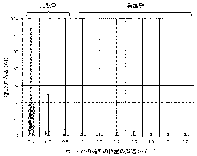
表1の風速は、ウェーハWの非回転時にウェーハWの端部の位置で測定した風速である。そして、上述したように、ウェーハWの非回転時に給気風量可変機構4と排気風量可変機構6を調整して表1に記載したそれぞれの風速が得られている。また、表1において、増加欠陥数は、洗浄処理後に測定したウェーハ表面の欠陥数から、洗浄処理前に測定したウェーハ表面の欠陥数を引いて算出した値の100枚のシリコンウェーハについての平均値である。
The wind speed in Table 1 is the wind speed measured at the position of the end of the wafer W when the wafer W is not rotating. Then, as described above, when the wafer W is not rotated, the supply air volume variable mechanism 4 and the exhaust air
表1及び図2より、実施例と比較例の結果を比較した。比較例のように、風速が0.4m/secでは、増加欠陥数は38個と非常に多く、増加欠陥数のバラツキも極めて大きかった。風速0.6及び0.8m/secでは0.4m/secと比較し、増加欠陥数は減少しているものの、実施例の風速1.0m/sec以上の条件と比較すると増加欠陥数及びバラツキの抑制効果は十分ではなかった。 From Table 1 and FIG. 2, the results of Examples and Comparative Examples were compared. As in the comparative example, when the wind speed was 0.4 m / sec, the number of increased defects was as large as 38, and the variation in the increased number of defects was extremely large. Although the number of increased defects is reduced at wind speeds of 0.6 and 0.8 m / sec as compared with 0.4 m / sec, the number of increased defects and variations are compared with those of the wind speed of 1.0 m / sec or more in the examples. The inhibitory effect was not sufficient.
一方、実施例の風速1.0m/sec以上では増加欠陥数はほぼ1個レベルまで低減されている。このように、ウェーハWの端部の位置の風速を1.0m/sec以上とすることにより、確実に顕著な増加欠陥数の抑制効果が得られる。 On the other hand, when the wind speed of the embodiment is 1.0 m / sec or more, the number of increased defects is reduced to almost one level. As described above, by setting the wind speed at the end portion of the wafer W to 1.0 m / sec or more, it is possible to surely obtain a remarkable effect of suppressing the number of increased defects.
なお、本発明は、上記実施形態に限定されるものではない。上記実施形態は、例示であり、本発明の特許請求の範囲に記載された技術的思想と実質的に同一な構成を有し、同様な作用効果を奏するものは、いかなるものであっても本発明の技術的範囲に包含される。 The present invention is not limited to the above embodiment. The above-described embodiment is an exemplification, and the present invention has substantially the same configuration as the technical idea described in the claims of the present invention, and any device that exhibits the same function and effect is the present invention. It is included in the technical scope of the invention.
1…チャンバー、 2…カップ部、 3…給気部、 4…給気風量可変機構、
5…排気部、 6…排気風量可変機構、 7…テーブル部、 8…ノズル部、
9…風速計、 10…圧力計、 11…風速計退避機構、 12…飛散した薬液、
13…薬液、 14…テーブル、 15…保持ピン、
100…本発明の枚葉式ウェーハ洗浄処理装置、 W…ウェーハ。
DESCRIPTION OF
5 ... Exhaust part, 6 ... Exhaust air volume variable mechanism, 7 ... Table part, 8 ... Nozzle part,
9 ... Anemometer, 10 ... Pressure gauge, 11 ... Anemometer retraction mechanism, 12 ... Spattered chemical,
13 ... Chemical solution, 14 ... Table, 15 ... Holding pin,
100: Single wafer cleaning apparatus of the present invention, W: Wafer.
Claims (6)
前記チャンバーに設けられた給気部と、
該給気部の風量を調整する給気風量可変機構と、
前記チャンバーに設けられた排気部と、
該排気部の風量を調整する排気風量可変機構と、
前記テーブル部に保持されるウェーハの端部の位置の風速を測定する風速計とを備えるものであることを特徴とする枚葉式ウェーハ洗浄処理装置。 A single wafer cleaning apparatus comprising a cup portion disposed in a chamber, a table portion disposed in the cup portion for holding and rotating the wafer, and a nozzle portion for supplying a chemical to the wafer. And
An air supply section provided in the chamber;
A supply air volume variable mechanism for adjusting the air volume of the supply section;
An exhaust section provided in the chamber;
An exhaust air volume variable mechanism for adjusting the air volume of the exhaust part;
A single wafer cleaning apparatus, comprising: an anemometer that measures an air velocity at a position of an end portion of a wafer held by the table portion.
前記テーブル部が回転していない時の、前記テーブル部に保持されたウェーハの端部の位置の風速を風速計により測定しつつ、該風速が1.0m/sec以上となるように、前記チャンバー内への給気の風量と前記チャンバー外への排気の風量のうち1つ以上を調整した状態で、前記テーブル部を回転させつつ前記ウェーハを洗浄処理することを特徴とするウェーハ洗浄処理方法。 A wafer having a cup portion disposed in a chamber and cleaning the wafer in a single wafer manner while supplying a chemical solution from a nozzle portion to a wafer held and rotated by a table portion disposed in the cup portion. A cleaning method,
The chamber is adjusted so that the wind speed is 1.0 m / sec or more while measuring the wind speed at the position of the end of the wafer held by the table section with the anemometer when the table section is not rotating. A wafer cleaning method, comprising: cleaning the wafer while rotating the table unit in a state where at least one of an air supply amount to the inside and an air flow amount to the outside of the chamber is adjusted.
6. The wafer cleaning method according to claim 4, wherein, when adjusting the wind speed at the position of the end portion of the wafer, a pressure difference between the inside and outside of the chamber is set within a range of 0 to 5 Pa. 6. .
Priority Applications (3)
| Application Number | Priority Date | Filing Date | Title |
|---|---|---|---|
| JP2016022872A JP6500797B2 (en) | 2016-02-09 | 2016-02-09 | Single wafer type wafer cleaning apparatus and wafer cleaning method |
| PCT/JP2016/005255 WO2017138056A1 (en) | 2016-02-09 | 2016-12-28 | Single wafer cleaning device and wafer cleaning method |
| TW106100975A TW201740451A (en) | 2016-02-09 | 2017-01-12 | Single wafer cleaning device and wafer cleaning method |
Applications Claiming Priority (1)
| Application Number | Priority Date | Filing Date | Title |
|---|---|---|---|
| JP2016022872A JP6500797B2 (en) | 2016-02-09 | 2016-02-09 | Single wafer type wafer cleaning apparatus and wafer cleaning method |
Publications (2)
| Publication Number | Publication Date |
|---|---|
| JP2017143141A true JP2017143141A (en) | 2017-08-17 |
| JP6500797B2 JP6500797B2 (en) | 2019-04-17 |
Family
ID=59563038
Family Applications (1)
| Application Number | Title | Priority Date | Filing Date |
|---|---|---|---|
| JP2016022872A Active JP6500797B2 (en) | 2016-02-09 | 2016-02-09 | Single wafer type wafer cleaning apparatus and wafer cleaning method |
Country Status (3)
| Country | Link |
|---|---|
| JP (1) | JP6500797B2 (en) |
| TW (1) | TW201740451A (en) |
| WO (1) | WO2017138056A1 (en) |
Cited By (2)
| Publication number | Priority date | Publication date | Assignee | Title |
|---|---|---|---|---|
| CN113394132A (en) * | 2021-04-29 | 2021-09-14 | 北京北方华创微电子装备有限公司 | Wafer cleaning equipment and control method thereof |
| JP7393907B2 (en) | 2018-10-31 | 2023-12-07 | 芝浦メカトロニクス株式会社 | Substrate processing equipment and substrate processing method |
Families Citing this family (1)
| Publication number | Priority date | Publication date | Assignee | Title |
|---|---|---|---|---|
| CN113838731B (en) * | 2020-06-08 | 2023-02-28 | 长鑫存储技术有限公司 | Semiconductor etching equipment |
Citations (3)
| Publication number | Priority date | Publication date | Assignee | Title |
|---|---|---|---|---|
| JPH1070100A (en) * | 1996-08-27 | 1998-03-10 | Matsushita Electric Ind Co Ltd | Substrate treatment equipment |
| JPH11111664A (en) * | 1997-09-30 | 1999-04-23 | Shibaura Mechatronics Corp | Treatment equipment of substrate |
| JP2002075951A (en) * | 2000-08-31 | 2002-03-15 | Super Silicon Kenkyusho:Kk | Washer for semiconductor wafer |
-
2016
- 2016-02-09 JP JP2016022872A patent/JP6500797B2/en active Active
- 2016-12-28 WO PCT/JP2016/005255 patent/WO2017138056A1/en active Application Filing
-
2017
- 2017-01-12 TW TW106100975A patent/TW201740451A/en unknown
Patent Citations (3)
| Publication number | Priority date | Publication date | Assignee | Title |
|---|---|---|---|---|
| JPH1070100A (en) * | 1996-08-27 | 1998-03-10 | Matsushita Electric Ind Co Ltd | Substrate treatment equipment |
| JPH11111664A (en) * | 1997-09-30 | 1999-04-23 | Shibaura Mechatronics Corp | Treatment equipment of substrate |
| JP2002075951A (en) * | 2000-08-31 | 2002-03-15 | Super Silicon Kenkyusho:Kk | Washer for semiconductor wafer |
Cited By (2)
| Publication number | Priority date | Publication date | Assignee | Title |
|---|---|---|---|---|
| JP7393907B2 (en) | 2018-10-31 | 2023-12-07 | 芝浦メカトロニクス株式会社 | Substrate processing equipment and substrate processing method |
| CN113394132A (en) * | 2021-04-29 | 2021-09-14 | 北京北方华创微电子装备有限公司 | Wafer cleaning equipment and control method thereof |
Also Published As
| Publication number | Publication date |
|---|---|
| TW201740451A (en) | 2017-11-16 |
| WO2017138056A1 (en) | 2017-08-17 |
| JP6500797B2 (en) | 2019-04-17 |
Similar Documents
| Publication | Publication Date | Title |
|---|---|---|
| JP5833046B2 (en) | Substrate liquid processing apparatus and air flow abnormality detection method | |
| TWI748628B (en) | Substrate processing method and substrate processing apparatus | |
| JP2007523463A (en) | Substrate processing apparatus and method | |
| WO2017138056A1 (en) | Single wafer cleaning device and wafer cleaning method | |
| JP2010279932A (en) | Film forming apparatus and method | |
| US11062899B2 (en) | Coated film removing apparatus | |
| JP6769166B2 (en) | Liquid treatment equipment and liquid treatment method | |
| JP5514667B2 (en) | Spin coating method | |
| KR20220107317A (en) | A cleaning apparatus, a polishing apparatus, and an apparatus and method for calculating the rotational speed of a substrate in the cleaning apparatus | |
| US20150318193A1 (en) | Substrate liquid treatment apparatus and substrate liquid treatment method | |
| JP6482402B2 (en) | Single wafer cleaning apparatus and wafer cleaning method | |
| JP2012064800A (en) | Wafer cleaning device | |
| TWI780296B (en) | Wafer cleaning apparatus and wafer cleaning method | |
| JP2005101497A (en) | Development method | |
| TW201313339A (en) | Wafer scrubber and wafer cleaning procedure | |
| JP2018125499A (en) | Semiconductor manufacturing apparatus and manufacturing method of semiconductor device | |
| JP7351331B2 (en) | Single-wafer spin cleaning drying method for silicon wafers | |
| JP2005252137A (en) | Cleaning method for substrate, and apparatus for substrate | |
| JPH10309509A (en) | Rotary substrate treating device and substrate treating method | |
| JP2005327906A (en) | Semiconductor manufacturing apparatus, and method for manufacturing semiconductor device | |
| JP2008258441A (en) | Substrate processing method, and substrate processor | |
| JP2002075951A (en) | Washer for semiconductor wafer | |
| JP2006332085A (en) | Spin dryer | |
| TWI803260B (en) | Semiconductor wafer cleaning device, semiconductor wafer cleaning method, and silicon wafer fabrication method | |
| JP2002158201A (en) | Cleaner for semiconductor wafers |
Legal Events
| Date | Code | Title | Description |
|---|---|---|---|
| A621 | Written request for application examination |
Free format text: JAPANESE INTERMEDIATE CODE: A621 Effective date: 20180116 |
|
| A131 | Notification of reasons for refusal |
Free format text: JAPANESE INTERMEDIATE CODE: A131 Effective date: 20181225 |
|
| A521 | Request for written amendment filed |
Free format text: JAPANESE INTERMEDIATE CODE: A523 Effective date: 20190212 |
|
| TRDD | Decision of grant or rejection written | ||
| A01 | Written decision to grant a patent or to grant a registration (utility model) |
Free format text: JAPANESE INTERMEDIATE CODE: A01 Effective date: 20190219 |
|
| A61 | First payment of annual fees (during grant procedure) |
Free format text: JAPANESE INTERMEDIATE CODE: A61 Effective date: 20190304 |
|
| R150 | Certificate of patent or registration of utility model |
Ref document number: 6500797 Country of ref document: JP Free format text: JAPANESE INTERMEDIATE CODE: R150 |
|
| R250 | Receipt of annual fees |
Free format text: JAPANESE INTERMEDIATE CODE: R250 |
|
| R250 | Receipt of annual fees |
Free format text: JAPANESE INTERMEDIATE CODE: R250 |
|
| R250 | Receipt of annual fees |
Free format text: JAPANESE INTERMEDIATE CODE: R250 |