JP2017139613A - Image processing apparatus, image processing method, and program - Google Patents

Image processing apparatus, image processing method, and program Download PDF

Info

Publication number
JP2017139613A
JP2017139613A JP2016019080A JP2016019080A JP2017139613A JP 2017139613 A JP2017139613 A JP 2017139613A JP 2016019080 A JP2016019080 A JP 2016019080A JP 2016019080 A JP2016019080 A JP 2016019080A JP 2017139613 A JP2017139613 A JP 2017139613A
Authority
JP
Japan
Prior art keywords
image
luminance
luminance range
microcomputer
luminance conversion
Prior art date
Legal status (The legal status is an assumption and is not a legal conclusion. Google has not performed a legal analysis and makes no representation as to the accuracy of the status listed.)
Pending
Application number
JP2016019080A
Other languages
Japanese (ja)
Other versions
JP2017139613A5 (en
Inventor
俊雄 簑島
Toshio Minoshima
俊雄 簑島
Current Assignee (The listed assignees may be inaccurate. Google has not performed a legal analysis and makes no representation or warranty as to the accuracy of the list.)
Canon Inc
Original Assignee
Canon Inc
Priority date (The priority date is an assumption and is not a legal conclusion. Google has not performed a legal analysis and makes no representation as to the accuracy of the date listed.)
Filing date
Publication date
Application filed by Canon Inc filed Critical Canon Inc
Priority to JP2016019080A priority Critical patent/JP2017139613A/en
Publication of JP2017139613A publication Critical patent/JP2017139613A/en
Publication of JP2017139613A5 publication Critical patent/JP2017139613A5/ja
Pending legal-status Critical Current

Links

Images

Abstract

PROBLEM TO BE SOLVED: To allow for checking how a captured HDR image is displayed by an HDR non-adaptive display apparatus.SOLUTION: A microcomputer (108) designates, with respect to an image in an HDR luminance range, a partial luminance range out of the HDR luminance range as an SDR luminance range, and identifies an image region outside the SDR luminance range, in the image of the HDR luminance range. Then, the microcomputer (108) controls an OSD part (106) to superimpose a zebra image onto the image region outside the SDR luminance range, with respect to the image of the HDR luminance range, and display the result on the screen of a liquid crystal panel (107).SELECTED DRAWING: Figure 1

Description

本発明は、高ダイナミックレンジの画像データを記録等する際の画像処理装置、画像処理方法、及びプログラムに関する。   The present invention relates to an image processing apparatus, an image processing method, and a program for recording high dynamic range image data.

デジタルカメラやデジタルビデオカメラといった画像記録装置は、被写体像をCMOSセンサやCCD等の撮像素子により画素単位で光電変換して、光の強度に応じた画像信号を生成し、更にデジタル変換した画像データに対して画像処理を行う。近年は、撮像素子の性能が向上しており、高ダイナミックレンジの画像データを生成できるようになりつつある。以下、高ダイナミックレンジを「HDR」と表記し、HDRの画像の撮影と記録が可能なデジタルビデオカメラ等の画像記録装置を「HDR対応カメラ」と表記する。   An image recording apparatus such as a digital camera or a digital video camera photoelectrically converts a subject image pixel by pixel using an image sensor such as a CMOS sensor or CCD, generates an image signal corresponding to the intensity of light, and further digitally converts the image data. Image processing is performed on In recent years, the performance of image pickup devices has improved, and image data with a high dynamic range can be generated. Hereinafter, the high dynamic range is referred to as “HDR”, and an image recording apparatus such as a digital video camera capable of capturing and recording HDR images is referred to as “HDR compatible camera”.

しかしながら、表示装置が対応できるダイナミックレンジには制限があり、HDR画像を表示できない表示装置が用いられた場合には、HDR画像を撮影時のダイナミックレンジでそのまま表示することはできない。HDR画像を表示できない表示装置としては、標準的な輝度範囲(標準ダイナミックレンジ)の画像表示にのみ対応している表示装置が考えられる。以下、標準ダイナミックレンジにのみ対応している表示装置を「HDR非対応表示装置」と表記し、また、標準ダイナミックレンジを「SDR」と表記する。このため、HDR画像データをHDR非対応表示装置に表示する場合には、HDR画像データをSDR画像データに変換する必要がある。   However, the dynamic range that can be supported by the display device is limited, and when a display device that cannot display an HDR image is used, the HDR image cannot be displayed as it is in the dynamic range at the time of shooting. As a display device that cannot display an HDR image, a display device that supports only image display in a standard luminance range (standard dynamic range) can be considered. Hereinafter, a display device that supports only the standard dynamic range is referred to as a “non-HDR compatible display device”, and the standard dynamic range is referred to as “SDR”. For this reason, when displaying HDR image data on a display device that does not support HDR, it is necessary to convert the HDR image data into SDR image data.

特許文献1には、HDRのデータと、HDRのデータをSDRのデータに変換する際に用いられる輝度変換情報とを記録し、表示装置がHDRに対応していない場合には、輝度変換情報に基づいてHDRのデータをSDRのデータに変換する技術が開示されている。   Patent Document 1 records HDR data and luminance conversion information used when converting HDR data into SDR data. If the display device does not support HDR, the luminance conversion information is recorded. A technique for converting HDR data into SDR data based on this is disclosed.

特開2015−8361号公報Japanese Patent Laying-Open No. 2015-8361

しかしながら、上述した従来の技術では、HDR対応カメラで撮影したHDRの画像が、HDR非対応表示装置でどのように表示されるかについては確認できない。   However, with the above-described conventional technology, it is not possible to confirm how an HDR image captured by an HDR-compatible camera is displayed on an HDR non-compatible display device.

そこで、本発明は、撮影された高ダイナミックレンジの画像が、高ダイナミックレンジに非対応の表示装置にどのように表示されるかを確認可能にすることを目的とする。   Therefore, an object of the present invention is to make it possible to check how a photographed high dynamic range image is displayed on a display device that does not support the high dynamic range.

本発明は、輝度のダイナミックレンジが第1の輝度範囲となっている画像に対して、前記第1の輝度範囲のうちの一部の輝度範囲を第2の輝度範囲として指定する指定手段と、前記第1の輝度範囲の画像の中で、前記第2の輝度範囲から外れる画像領域に対して、所定の画像を合成して、画面に表示される画像を生成する合成手段と、を有することを特徴とする。   The present invention provides a designation means for designating a part of the first luminance range as a second luminance range for an image having a luminance dynamic range of the first luminance range; Synthesizing means for synthesizing a predetermined image with an image region out of the second luminance range in the image of the first luminance range and generating an image displayed on the screen. It is characterized by.

本発明によれば、撮影された高ダイナミックレンジの画像が、高ダイナミックレンジに非対応の表示装置でどのように表示されるかを確認可能となる。   ADVANTAGE OF THE INVENTION According to this invention, it becomes possible to confirm how the image | photographed high dynamic range image is displayed with the display apparatus not corresponding to a high dynamic range.

第1実施形態のカメラの概略的な内部構成例を示す図である。It is a figure which shows the schematic internal structural example of the camera of 1st Embodiment. 階調変換処理の概要説明に用いる図である。It is a figure used for outline | summary description of a gradation conversion process. SDRの輝度範囲外の画像領域へのゼブラ表示のフローチャートである。It is a flowchart of the zebra display to the image area | region outside the brightness | luminance range of SDR. 第1実施形態でSDRの輝度範囲を指定する際のUI例を示す図である。It is a figure which shows UI example at the time of designating the brightness | luminance range of SDR in 1st Embodiment. 輝度変換テーブルの説明に用いる図である。It is a figure used for description of a luminance conversion table. 第1実施形態における画像記録動作のフローチャートである。It is a flowchart of the image recording operation | movement in 1st Embodiment. メタデータ記録の設定を行う際のUI例を示す図である。It is a figure which shows the example of UI at the time of performing setting of metadata recording. 第1実施形態の管理情報例を示す図である。It is a figure which shows the example of management information of 1st Embodiment. 第1実施形態のフォルダの構成例を示す図である。It is a figure which shows the structural example of the folder of 1st Embodiment. 第1実施形態の画像再生動作のフローチャートである。It is a flowchart of the image reproduction operation | movement of 1st Embodiment. 第1実施形態の再生出力時の輝度変換設定UIと画像例を示す図である。It is a figure which shows the luminance conversion setting UI at the time of reproduction | regeneration output of 1st Embodiment, and an example of an image. 第2実施形態のカメラの概略的な内部構成例を示す図である。It is a figure which shows the schematic internal structural example of the camera of 2nd Embodiment. 第2実施形態でSDRの輝度範囲を指定する際のUI例を示す図である。It is a figure which shows UI example at the time of designating the brightness | luminance range of SDR in 2nd Embodiment. 第2実施形態の管理情報例を示す図である。It is a figure which shows the example of management information of 2nd Embodiment. 第2実施形態のフォルダの構成例を示す図である。It is a figure which shows the structural example of the folder of 2nd Embodiment. 第2実施形態の画像再生動作のフローチャートである。It is a flowchart of the image reproduction operation | movement of 2nd Embodiment. 第2実施形態の再生出力時の輝度変換設定UI例を示す図である。It is a figure which shows the luminance conversion setting UI example at the time of reproduction | regeneration output of 2nd Embodiment.

以下、図面を参照しながら本発明の好適な実施の形態について説明する。
<第1実施形態>
図1は、第1実施形態に係る画像処理装置の一適用例であるカメラ100の概略的な内部構成例を示す図である。本実施形態のカメラ100は、高ダイナミックレンジ(HDR)の画像データを撮影して記録するデジタルカメラやデジタルビデオカメラなどのHDR対応カメラであるとする。
Hereinafter, preferred embodiments of the present invention will be described with reference to the drawings.
<First Embodiment>
FIG. 1 is a diagram illustrating a schematic internal configuration example of a camera 100 as an application example of the image processing apparatus according to the first embodiment. Assume that the camera 100 of the present embodiment is an HDR-compatible camera such as a digital camera or a digital video camera that captures and records high dynamic range (HDR) image data.

図1において、マイクロコンピュータ108(以下、マイコン108とする。)は、カメラ100の全体を制御する。レンズユニット101は、集光のための固定レンズ群、変倍レンズ群、絞り、変倍レンズ群の動きで移動した結像位置を補正する機能と焦点調節を行う機能とを兼ね備えた補正レンズ群により構成されている。レンズユニット101によって、センサ102の結像面上に被写体像が結像される。   In FIG. 1, a microcomputer 108 (hereinafter referred to as a microcomputer 108) controls the entire camera 100. The lens unit 101 is a correction lens group that has both a function of correcting the imaging position moved by the movement of the fixed lens group, the variable power lens group, the stop, and the variable power lens group for focusing, and the function of performing focus adjustment. It is comprised by. An object image is formed on the image forming surface of the sensor 102 by the lens unit 101.

センサ102は、撮像素子であり、光を電荷に変換してアナログ撮像信号を生成する。本実施形態のカメラ100は、HDRの画像撮影が可能となされており、センサ102はHDRに対応した撮像素子となされている。本実施形態では、センサ102は、アナログデジタル変換部を含み、一例として12ビットのデジタルデータ出力を行うセンサとなされている。本実施形態のカメラ100では、一例として、動画の画像データが得られるとする。また、センサ102には、カラー画像を生成するためのR(赤),G(緑),B(青)に対応したカラーフィルタも備えられているとする。このため、センサ102からはそれぞれ12ビットのR,G,Bの画像データが出力される。   The sensor 102 is an image sensor and converts light into electric charges to generate an analog image signal. The camera 100 of the present embodiment is capable of taking HDR images, and the sensor 102 is an image sensor that supports HDR. In the present embodiment, the sensor 102 includes an analog-digital conversion unit, and is a sensor that outputs 12-bit digital data as an example. In the camera 100 of the present embodiment, as an example, it is assumed that moving image data is obtained. The sensor 102 is also provided with color filters corresponding to R (red), G (green), and B (blue) for generating a color image. Therefore, 12-bit R, G, and B image data are output from the sensor 102, respectively.

本実施形態のカメラ100では、センサ102以降の各構成においても12ビットのデータを処理可能となされている。画像処理部103は、センサ102から送られてきた画像データに適したホワイトバランスのゲイン値を算出して、画像データに乗算する。その後、画像処理部103は、各12ビットのR,G,Bの画像データを、各12ビットのY,Cb,Crの画像データ(以下、YCbCrデータと表記する。)に変換して、画像データの輝度値(Y値)を算出する。画像処理部103による画像処理後の画像データは、RAM111に一時的に保持される。また、画像処理部103は、後述するダイナミックレンジ情報も生成する。   In the camera 100 of the present embodiment, 12-bit data can be processed in each of the components subsequent to the sensor 102. The image processing unit 103 calculates a white balance gain value suitable for the image data transmitted from the sensor 102 and multiplies the image data. After that, the image processing unit 103 converts each 12-bit R, G, and B image data into 12-bit Y, Cb, and Cr image data (hereinafter referred to as YCbCr data), and the image. The brightness value (Y value) of the data is calculated. Image data after image processing by the image processing unit 103 is temporarily held in the RAM 111. The image processing unit 103 also generates dynamic range information described later.

圧縮伸張回路104は、RAM111の画像データをいわゆるMPEGやH.264等の規格で圧縮して圧縮ビデオデータを生成(エンコード)した後、その圧縮ビデオデータをRAM111に保持させる。また、圧縮伸張回路104は、MPEGやH.264等の規格で圧縮された圧縮ビデオデータを伸張(デコード)する機能も兼ね備えている。また、図示は省略しているが、本実施形態のカメラ100はマイクユニットやスピーカーをも備えており、圧縮伸張回路104は、画像データと共に音声データの圧縮伸張をも行う。そして、圧縮伸張回路104は、前述の圧縮データに音声データを多重化する。   The compression / decompression circuit 104 converts the image data in the RAM 111 into so-called MPEG or H.264. The compressed video data is generated (encoded) by compression according to a standard such as H.264, and the compressed video data is held in the RAM 111. The compression / decompression circuit 104 is an MPEG or H.264. It also has a function of decompressing (decoding) compressed video data compressed by a standard such as H.264. Although not shown, the camera 100 according to the present embodiment also includes a microphone unit and a speaker, and the compression / decompression circuit 104 performs compression / expansion of audio data together with image data. Then, the compression / decompression circuit 104 multiplexes the audio data with the above-described compressed data.

ROM110は、フラッシュROMであり、マイコン108が実行するプログラムなどを格納している。また、ROM110の一部領域は、バックアップ用として、システムの状態などを保持するために使用される。RAM111は、マイコン108、画像処理部103、圧縮伸張回路104、後述する輝度情報生成部105や輝度変換部114などがワークメモリとして使用する揮発性メモリである。メモリカードコントローラ112は、FAT(File Allocation Table)ファイルシステムなどコンピュータに用いられるフォーマットにしたがって、メモリカード113に対するデータの書き込みと読み出しとを制御する。圧縮伸張回路104で生成されてRAM111に一時的に記憶された圧縮ビデオデータは、メモリカードコントローラ112によりメモリカード113に記録される。メモリカード113は、圧縮伸張回路104で生成された圧縮ビデオデータや、マイコン108がRAM111上に生成した後述する管理情報等を、FATファイルシステムなどの所定のフォーマットに従って記録する記録媒体である。また、メモリカード113は、カメラ100から取り外し可能な着脱可能なSDカード等の記録媒体であり、ビデオカメラ以外にPC等にも装着することができる。   The ROM 110 is a flash ROM, and stores a program executed by the microcomputer 108. In addition, a partial area of the ROM 110 is used for backup and for holding the system state and the like. The RAM 111 is a volatile memory used as a work memory by the microcomputer 108, the image processing unit 103, the compression / decompression circuit 104, the luminance information generation unit 105, the luminance conversion unit 114, and the like which will be described later. The memory card controller 112 controls writing and reading of data to and from the memory card 113 in accordance with a format used in a computer such as a FAT (File Allocation Table) file system. The compressed video data generated by the compression / decompression circuit 104 and temporarily stored in the RAM 111 is recorded on the memory card 113 by the memory card controller 112. The memory card 113 is a recording medium for recording compressed video data generated by the compression / decompression circuit 104, management information described later generated by the microcomputer 108 on the RAM 111, and the like according to a predetermined format such as a FAT file system. The memory card 113 is a recording medium such as a removable SD card that can be removed from the camera 100, and can be mounted on a PC or the like in addition to the video camera.

バス116は、本実施形態のカメラ100が備える各ブロックの間でデータのやり取りを行うためのものである。外部出力部115は、マイコン108による制御の下、外部の機器、例えば表示装置などに、画像データ等を出力するものである。外部出力部115から外部に出力される画像データは、画像処理部103から出力されてRAM111に記憶された画像データや、メモリカード113から読み出されて圧縮伸張回路104でデコードされてRAM111に記憶された画像データなどである。なお、外部出力部115は、ケーブル等を介して外部機器と有線接続がなされるものに限定されず、無線接続を行うものであってもよい。   The bus 116 is for exchanging data between the blocks included in the camera 100 of the present embodiment. The external output unit 115 outputs image data or the like to an external device such as a display device under the control of the microcomputer 108. Image data output from the external output unit 115 to the outside is image data output from the image processing unit 103 and stored in the RAM 111, or read from the memory card 113, decoded by the compression / decompression circuit 104, and stored in the RAM 111. Image data. Note that the external output unit 115 is not limited to a unit that is wired to an external device via a cable or the like, and may be a unit that performs wireless connection.

液晶パネル107は、前述した12ビットのHDR画像データを表示可能なパネルである。液晶パネル107には、本実施形態のカメラ100が撮影したHDR画像や、メモリカードコントローラ112を介してメモリカード113から読み出されて圧縮伸張回路104でデコードされた画像等が表示される。OSD部106は、例えば、各種設定メニューやタイトル、時間などの情報をオンスクリーンディスプレイ(OSD)用の表示情報として、HDR画像データに重畳させることができる。この場合、液晶パネル107には、OSD用の表示情報が合成されたHDR画像が表示されることになる。また、OSD部106は、OSD用の表示情報が合成されたHDR画像のデータを、外部出力部115を介して接続された外部の表示装置に出力することも可能である。   The liquid crystal panel 107 is a panel capable of displaying the above-described 12-bit HDR image data. On the liquid crystal panel 107, an HDR image taken by the camera 100 of the present embodiment, an image read from the memory card 113 via the memory card controller 112 and decoded by the compression / decompression circuit 104, and the like are displayed. For example, the OSD unit 106 can superimpose information such as various setting menus, titles, and times on the HDR image data as display information for an on-screen display (OSD). In this case, an HDR image in which display information for OSD is combined is displayed on the liquid crystal panel 107. The OSD unit 106 can also output the HDR image data combined with the OSD display information to an external display device connected via the external output unit 115.

なお、外部出力部115に接続される外部の表示装置は、HDR画像を表示可能な装置だけでなく、HDR画像を表示することができないHDR非対応表示装置の場合も考えられる。HDR非対応表示装置としては、例えば、標準的な輝度範囲(標準ダイナミックレンジ:SDR)の画像表示にのみ対応している表示装置が考えられる。本実施形態では、SDRのみに対応したHDR非対応表示装置は、一例として、8ビットデータを扱う表示装置であるとする。詳細については後述するが、外部出力部115を介してHDR非対応表示装置が接続される場合、本実施形態のカメラ100は、HDRの画像データをSDRの画像データに変換して出力可能となされている。   Note that the external display device connected to the external output unit 115 is not limited to a device capable of displaying an HDR image, but may be a non-HDR compatible display device that cannot display an HDR image. As a display device that does not support HDR, for example, a display device that supports only image display in a standard luminance range (standard dynamic range: SDR) is conceivable. In the present embodiment, it is assumed that an HDR non-compatible display device that supports only SDR is a display device that handles 8-bit data as an example. Although details will be described later, when a non-HDR compatible display device is connected via the external output unit 115, the camera 100 according to the present embodiment can convert HDR image data into SDR image data and output the converted image data. ing.

操作スイッチ群109は、ユーザが指示等を入力するために設けられている。操作スイッチ群109には、例えば、主に撮影を行うためのカメラモードや、主に画像を再生表示させるための再生モード、電源をオフにするパワーオフモード等を、ユーザが選択して指示するためのスイッチ等が設けられている。また、操作スイッチ群109にはいわゆるタッチパネルも含まれる。タッチパネルは、例えば液晶パネル107の画面上に配されている。ユーザにより操作スイッチ群109のタッチパネルへの操作がなされた場合、マイコン108は、タッチパネルに対する以下の操作を検出できる。マイコン108は、タッチパネルに対し、指等が、触れたこと(タッチダウン)、触れている状態(タッチオン)、触れたまま移動する状態(ムーブ)、触れていた指等を離したこと(タッチアップ)、何も触れていない状態(タッチオフ)等の操作を検出できる。これら操作の情報やタッチパネル上に指等が触れているときの位置座標の情報は、マイコン108に通知され、このときのマイコン108は、それら通知された情報に基づいて、タッチパネル上に対しどのような操作が行なわれたかを判定する。また、マイコン108は、位置座標の変化に基づき、例えばムーブによりタッチパネル上で移動する指等の移動方向を、タッチパネル上の垂直・水平成分毎に検出可能である。また、マイコン108は、タッチダウンから一定のムーブを経てタッチアップがなされた場合、ストロークが描かれたことを検出する。なお、素早くストロークを描く操作はフリックと呼ばれる。フリックは、タッチパネル上に指等を触れたまま、ある程度の距離だけ素早く動かして、そのまま離すといった操作であり、言い換えればタッチパネル上を指で弾くように素早くなぞる操作である。マイコン108は、所定距離以上で且つ所定速度以上のムーブがされたことを検出し、そのままタッチアップがなされたことを検出した場合には、フリックが行なわれたと判定する。また、マイコン108は、所定距離以上で且つ所定速度未満のムーブがなされたことを検出した場合には、ドラッグが行なわれたと判定する。タッチパネルは、抵抗膜方式や静電容量方式、表面弾性波方式、赤外線方式、電磁誘導方式、画像認識方式、光センサ方式等、様々な方式のタッチパネルのうちいずれの方式のものが用いられてもよい。   The operation switch group 109 is provided for a user to input an instruction or the like. In the operation switch group 109, for example, the user selects and instructs a camera mode mainly for photographing, a playback mode mainly for reproducing and displaying an image, a power-off mode for turning off the power, and the like. A switch or the like is provided. The operation switch group 109 includes a so-called touch panel. The touch panel is disposed on the screen of the liquid crystal panel 107, for example. When the user operates the touch panel of the operation switch group 109, the microcomputer 108 can detect the following operation on the touch panel. The microcomputer 108 touches the touch panel (touch down), touches (touch on), moves while touching (move), releases the touched finger (touch up) ), An operation such as a state where nothing is touched (touch-off) can be detected. Information on these operations and information on the position coordinates when a finger or the like is touching the touch panel are notified to the microcomputer 108, and the microcomputer 108 at this time performs the operation on the touch panel based on the notified information. It is determined whether a correct operation has been performed. Further, the microcomputer 108 can detect the moving direction of a finger or the like moving on the touch panel by a move, for each vertical / horizontal component on the touch panel, based on the change of the position coordinates. Further, the microcomputer 108 detects that a stroke is drawn when a touch-up is made through a certain move from the touch-down. The operation of drawing a stroke quickly is called flicking. A flick is an operation in which a finger or the like is touched on the touch panel, quickly moved by a certain distance, and then released. In other words, it is an operation in which a finger is quickly traced on the touch panel. The microcomputer 108 determines that a flick has been performed when it detects that a move at a predetermined distance or more and a predetermined speed or more has been performed, and it has detected that a touch-up has been performed. Further, when the microcomputer 108 detects that the move is performed at a predetermined distance or more and less than a predetermined speed, it determines that the drag has been performed. The touch panel can be any of various types of touch panels such as a resistive film type, a capacitance type, a surface acoustic wave type, an infrared type, an electromagnetic induction type, an image recognition type, and an optical sensor type. Good.

輝度変換部114は、HDR画像データに対し、輝度変換情報に応じた階調変換処理を行う。詳細については後述するが、輝度変換情報は、輝度情報生成部105により生成される。本実施形態において、階調変換処理は、HDR画像における12ビットの輝度の階調を、8ビットの階調に変換してSDR画像を生成する階調処理であり、以下、特に輝度に関する階調変換を「輝度変換」と表記する。本実施形態のカメラ100は、例えばカメラモードである場合、例えばユーザからの指示に応じて、撮影されてRAM111に一時的に記憶されたHDR画像データに対して、輝度変換部114による輝度変換を行うことが可能となされている。また、本実施形態のカメラ100は、輝度変換部114にて輝度変換が行われた後(以下、「輝度変換後」と表記する)の画像データを、マイコン108による制御の下、液晶パネル107や、外部出力部115を介して外部表示装置に送ることも可能である。なお、以下の説明では、「輝度変換が行われた後」を「輝度変換後」と表記し、一方、「輝度変換が行われる前」を「輝度変換前」と表記することにする。   The luminance conversion unit 114 performs gradation conversion processing according to the luminance conversion information on the HDR image data. Although details will be described later, the luminance conversion information is generated by the luminance information generation unit 105. In the present embodiment, the gradation conversion process is a gradation process for generating an SDR image by converting a 12-bit luminance gradation in an HDR image into an 8-bit gradation. The conversion is expressed as “luminance conversion”. For example, when the camera 100 of the present embodiment is in the camera mode, the luminance conversion unit 114 performs luminance conversion on HDR image data that has been captured and temporarily stored in the RAM 111, for example, in response to an instruction from the user. It is possible to do. In the camera 100 of the present embodiment, image data after luminance conversion is performed by the luminance conversion unit 114 (hereinafter referred to as “after luminance conversion”) is controlled by the microcomputer 108 under the control of the liquid crystal panel 107. Alternatively, it can be sent to an external display device via the external output unit 115. In the following description, “after luminance conversion” is described as “after luminance conversion”, while “before luminance conversion” is expressed as “before luminance conversion”.

以下、HDR画像をSDR画像に変換する階調変換のうち特に輝度変換の概要について、図2(a)と図2(b)を参照しながら説明する。なお、図2(a)と図2(b)は、本実施形態において、後述するようなユーザによるSDRの輝度範囲指定がなされない場合の輝度変換例を示している。図2(a)は、輝度変換前のYCbCrの12ビットの画像値と、輝度変換後のYCbCrの8ビットの画素値との対応関係を表すグラフである。図2(a)の縦軸が輝度変換後の画素値を、横軸が輝度変換前の画素値を示しており、画素値=輝度値(Y値)である。   Hereinafter, an outline of luminance conversion among gradation conversions for converting an HDR image into an SDR image will be described with reference to FIGS. 2 (a) and 2 (b). 2A and 2B show an example of luminance conversion in the present embodiment when the SDR luminance range is not designated by the user as described later. FIG. 2A is a graph showing the correspondence between the 12-bit YCbCr image value before luminance conversion and the 8-bit YCbCr pixel value after luminance conversion. In FIG. 2A, the vertical axis indicates the pixel value after luminance conversion, and the horizontal axis indicates the pixel value before luminance conversion, where pixel value = luminance value (Y value).

図2(a)に示すように、輝度変換は、12ビットのYCbCrデータを、8ビットのYCbCrデータに変換するような処理となされている。ただし、12ビットのデータは「0」から「4095」までの値をとることができる一方で、8ビットのデータは「0」から「255」までの値しかとることができない。このため、輝度変換では、12ビットのYCbCrデータのうち、輝度値が「0〜15」の画素値は8ビットのデータでは「0」にし、輝度値が「16〜31」の画素値は8ビットのデータでは「1」(以下同様)にするような処理が行われる。輝度情報生成部105は、このような12ビットのデータを8ビットのデータに変換するためのテーブル(以下、輝度変換テーブルと表記する。)の情報を生成する。図2(b)は、輝度変換テーブルの一例を示している。図2(b)に示す輝度変換テーブルは、12ビットのYCbCrデータである輝度変換前の画素値と、8ビットのYCbCrデータである輝度変換後の画素値との対応関係を表すテーブルである。この輝度変換テーブルは、輝度変換前の画素値「0〜15」は変換後には「0」、変換前の画素値「16〜31」は変換後には「1」のように、変換前の画素値が「16」上がる毎に、変換後の画素値が「1」上がるようなテーブルとなされる。   As shown in FIG. 2A, the luminance conversion is a process of converting 12-bit YCbCr data into 8-bit YCbCr data. However, while 12-bit data can take values from “0” to “4095”, 8-bit data can take only values from “0” to “255”. For this reason, in the luminance conversion, among the 12-bit YCbCr data, the pixel value with the luminance value “0 to 15” is set to “0” with the 8-bit data, and the pixel value with the luminance value “16 to 31” is 8 For bit data, a process of setting “1” (hereinafter the same) is performed. The luminance information generation unit 105 generates information of a table (hereinafter referred to as a luminance conversion table) for converting such 12-bit data into 8-bit data. FIG. 2B shows an example of the luminance conversion table. The brightness conversion table shown in FIG. 2B is a table representing a correspondence relationship between pixel values before brightness conversion, which is 12-bit YCbCr data, and pixel values after brightness conversion, which is 8-bit YCbCr data. In this luminance conversion table, the pixel value “0-15” before luminance conversion is “0” after conversion, the pixel value “16-31” before conversion is “1” after conversion, and so on. Each time the value is increased by “16”, the converted pixel value is increased by “1”.

ここで、本実施形態のカメラ100は、操作スイッチ群109を介したユーザによる指定に応じて、HDR画像の輝度範囲内においてSDRに対応した輝度範囲を輝度の高低方向へ任意に移動させるような調整が可能となされている。HDR画像の輝度範囲内でSDRの輝度範囲をユーザが任意に指定する際の具体的なユーザーインタフェース例については後述する。本実施形態のカメラ100では、操作スイッチ群109を介してユーザによりSDRの輝度範囲の指定がなされた場合、輝度情報生成部105は、その指定された輝度範囲に応じた重み付けがなされた輝度変換情報を生成する。詳細は後述するが、輝度変換生成部105は、ユーザにより指定されたSDRの輝度範囲に応じて重み付けがなされた輝度変換テーブルを生成する。この場合の輝度変換テーブルは、前述の図2(b)に示した輝度変換テーブルとは異なる。   Here, the camera 100 according to the present embodiment arbitrarily moves the luminance range corresponding to the SDR in the luminance range of the HDR image in accordance with the designation by the user via the operation switch group 109. Adjustment is possible. A specific user interface example when the user arbitrarily designates the SDR luminance range within the HDR image luminance range will be described later. In the camera 100 according to the present embodiment, when the user designates the SDR luminance range via the operation switch group 109, the luminance information generation unit 105 performs luminance conversion weighted according to the designated luminance range. Generate information. Although details will be described later, the luminance conversion generation unit 105 generates a luminance conversion table weighted according to the luminance range of the SDR designated by the user. The brightness conversion table in this case is different from the brightness conversion table shown in FIG.

また、ユーザによりSDRの輝度範囲が指定された場合、マイコン108は、HDR画像のうち、SDRの輝度範囲内に輝度値が入らない各画素が集まっている画像領域を算出する。すなわち、マイコン108は、HDR画像のうち、SDRの輝度範囲内に輝度値が入らない画像領域を特定する。そして、マイコン108は、その特定した画像領域を、をOSD部106に通知する。この通知を受けたOSD部106は、特定した画像領域に対応したゼブラ模様(縞模様)の画像を生成し、ゼブラ模様の画像をOSD用の表示情報として画像データに重畳させる。これにより、液晶パネル107の画面上には、ユーザにより指定されたSDRの輝度範囲内に入らない画像領域がゼブラ模様になされた画像が、表示されることになる。以下、ゼブラ模様の画像を「ゼブラ画像」と表記し、ゼブラ画像を画像に合成して表示させることを「ゼブラ表示」と表記する。このようなゼブラ表示が行われることで、ユーザは、撮影されたHDR画像の中で意図した画像領域が、指定したSDRの輝度範囲内に入っているかどうかを視覚的に確認することができることになる。なお、本実施形態ではゼブラ画像をHDR画像に合成する例を挙げたが、合成されるのは他の模様等の画像であってもよい。また、本実施形態の場合、ゼブラ画像を合成するのみの簡単な処理のみ行えばよいため、カメラ100における画像処理の負担は少ない。   When the SDR luminance range is designated by the user, the microcomputer 108 calculates an image region in which each pixel having a luminance value not included in the SDR luminance range is gathered in the HDR image. In other words, the microcomputer 108 identifies an image area in the HDR image in which the luminance value does not fall within the SDR luminance range. Then, the microcomputer 108 notifies the OSD unit 106 of the specified image area. Upon receiving this notification, the OSD unit 106 generates a zebra pattern (striped pattern) image corresponding to the specified image area, and superimposes the zebra pattern image on the image data as display information for OSD. As a result, on the screen of the liquid crystal panel 107, an image in which an image region that does not fall within the luminance range of the SDR designated by the user is formed in a zebra pattern is displayed. Hereinafter, a zebra pattern image is referred to as a “zebra image”, and the display of a zebra image combined with an image is referred to as a “zebra display”. By performing such zebra display, the user can visually confirm whether the intended image area in the captured HDR image is within the luminance range of the designated SDR. Become. In the present embodiment, an example in which a zebra image is combined with an HDR image has been described, but an image such as another pattern may be combined. In the case of the present embodiment, only a simple process of synthesizing the zebra image needs to be performed, so that the image processing burden on the camera 100 is small.

また、本実施形態によれば、前述したように、ユーザは、操作スイッチ群109を介した指示入力により、HDR画像の輝度範囲内でSDRの輝度範囲を輝度の高低方向へ移動させるような任意の指定が可能となされている。したがって、ユーザは、液晶パネル107に表示されたHDR画像の中で、意図した画像領域がゼブラ表示されてしまわないように、SDRに対応した輝度範囲を、輝度の高低方向へ移動させるような指定を行うことができる。   Further, according to the present embodiment, as described above, the user can arbitrarily move the SDR luminance range in the luminance range of the HDR image within the luminance range of the HDR image by an instruction input via the operation switch group 109. Can be specified. Therefore, the user designates that the luminance range corresponding to the SDR is moved in the high and low directions so that the intended image area is not displayed in the zebra display in the HDR image displayed on the liquid crystal panel 107. It can be performed.

図1に説明を戻し、輝度情報生成部105は、輝度変換テーブルと後述するダイナミックレンジ情報とを含む輝度変換情報を生成する。操作スイッチ群109を介してユーザから記録指示が入力された場合、マイコン108は、輝度情報生成部105にて生成された輝度変換情報を、メモリカードコントローラ112を介して圧縮ビデオデータと関連付けてメモリカード113に記録させる。また、操作スイッチ群109を介してユーザから再生指示が入力された場合、マイコン108は、メモリカードコントローラ112を介してメモリカード113から圧縮ビデオデータと輝度変換情報とを読み出させ、RAM111に一時的に記憶させる。そして、マイコン108による制御の下、圧縮伸張回路104は、RAM111から読み出された圧縮ビデオデータをデコードする。このときの輝度変換部114は、そのデコードされた画像データを、輝度変換情報内の輝度変換テーブルに基づいて輝度変換することができる。再生モードにおいて、輝度変換部114にて輝度変換された後の画像データは、マイコン108による制御の下、液晶パネル107や、外部出力部115を介して外部表示装置に送られる。   Returning to FIG. 1, the luminance information generation unit 105 generates luminance conversion information including a luminance conversion table and dynamic range information described later. When a recording instruction is input from the user via the operation switch group 109, the microcomputer 108 associates the luminance conversion information generated by the luminance information generation unit 105 with the compressed video data via the memory card controller 112 and stores the memory. It is recorded on the card 113. When a reproduction instruction is input from the user via the operation switch group 109, the microcomputer 108 reads out the compressed video data and the luminance conversion information from the memory card 113 via the memory card controller 112, and temporarily stores them in the RAM 111. Memorize. Then, under the control of the microcomputer 108, the compression / decompression circuit 104 decodes the compressed video data read from the RAM 111. The luminance conversion unit 114 at this time can perform luminance conversion on the decoded image data based on the luminance conversion table in the luminance conversion information. In the reproduction mode, the image data after the luminance conversion by the luminance conversion unit 114 is sent to the external display device via the liquid crystal panel 107 and the external output unit 115 under the control of the microcomputer 108.

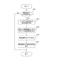
図3は、本実施形態のカメラ100において、ユーザにより指定されたSDRの輝度範囲外の画像領域に対してゼブラ表示を行う場合の処理のフローチャートである。図3のフローチャートにおける各処理ステップは、カメラ100のマイコン108が、ROM110に保存されている本実施形態に係る画像処理プログラムを実行して各部を制御することにより実現される。なお、以下の説明では、図3の各処理ステップS301〜ステップS305を、S301〜S305と略記する。本実施形態のカメラ100において、画像の撮影がなされている場合、センサ102は動画のフレーム毎の撮像画像を取り込み、そのフレーム毎の撮像画像のデータが画像処理部103で処理されてRAM111に送られる。図3のフローチャートは、動画の撮影が開始されたことでスタートする。   FIG. 3 is a flowchart of processing when the camera 100 according to the present embodiment performs zebra display on an image area outside the luminance range of the SDR specified by the user. Each processing step in the flowchart of FIG. 3 is realized by the microcomputer 108 of the camera 100 executing the image processing program according to the present embodiment stored in the ROM 110 to control each unit. In the following description, the processing steps S301 to S305 in FIG. 3 are abbreviated as S301 to S305. In the camera 100 of this embodiment, when an image is captured, the sensor 102 captures a captured image for each frame of the moving image, and the captured image data for each frame is processed by the image processing unit 103 and sent to the RAM 111. It is done. The flowchart of FIG. 3 starts when the shooting of a moving image is started.

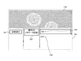
図3のS301では、マイコン108は、撮影されたHDR画像を液晶パネル107等に表示させる際に、前述したゼブラ表示を行う設定(ゼブラ表示の設定が有効(ON))になっているか否かを判断する。ここで、本実施形態の場合、ユーザは、操作スイッチ群109の操作を介することにより、ゼブラ表示を有効(ON)又は無効(OFF)に設定することができる。図4(a)は、ユーザが操作スイッチ群109を操作してゼブラ表示を有効又は無効に設定する際のユーザーインタフェース(以下、UIと表記する。)画面401の一例を示す。この図4(a)は、マイコン108による制御の下で、OSD部106により後述する各種メニュー画像等がHDR画像に合成されて液晶パネル107等に表示された画面例である。   In S301 of FIG. 3, when the microcomputer 108 displays the photographed HDR image on the liquid crystal panel 107 or the like, it is determined whether or not the setting for performing the zebra display described above (setting of the zebra display is valid (ON)). Judging. Here, in the case of the present embodiment, the user can set the zebra display to valid (ON) or invalid (OFF) by operating the operation switch group 109. FIG. 4A shows an example of a user interface (hereinafter referred to as UI) screen 401 when the user operates the operation switch group 109 to enable or disable the zebra display. FIG. 4A shows an example of a screen in which various menu images, which will be described later, are combined with an HDR image by the OSD unit 106 and displayed on the liquid crystal panel 107 and the like under the control of the microcomputer 108.

図4(a)のUI画面401には、センサ102から出力されて画像処理部103の画像処理を介してRAM111に一時記憶されたHDR画像データに基づくHDR画像430が表示されている。HDR画像430は、例えば打ち上げ花火を撮影した画像であるとする。また、図4(a)のUI画面401には、液晶パネル107の表示設定を行うパネル設定メニュー441の下位メニューとして、ゼブラ表示の設定の際に用いられる輝度範囲外ゼブラ表示メニュー442が表示される。さらに、このメニュー442の下位メニューには、ゼブラ表示を有効(ON)に設定する際に選択されるONメニュー443と、無効(OFF)に設定する際に選択されるOFFメニュー444とが用意されている。図4(a)のUI画面401の例は、操作スイッチ群109の操作を介してユーザによりONメニュー443が選択されて、例えばハイライト表示されている状態を表している。そして、S301において、マイコン108は、ゼブラ表示が有効(ON)に設定されていると判断した場合にはS302に処理を進め、一方、無効(OFF)に設定されていると判断した場合には図3のフローチャートの処理を終了する。   On the UI screen 401 in FIG. 4A, an HDR image 430 based on the HDR image data output from the sensor 102 and temporarily stored in the RAM 111 through image processing of the image processing unit 103 is displayed. It is assumed that the HDR image 430 is an image obtained by shooting, for example, a skyrocket. In addition, on the UI screen 401 in FIG. 4A, a zebra display menu 442 that is out of the luminance range used when setting the zebra display is displayed as a lower menu of the panel setting menu 441 for performing display setting of the liquid crystal panel 107. The Further, the lower menu of this menu 442 includes an ON menu 443 that is selected when the zebra display is set to be valid (ON) and an OFF menu 444 that is selected when the zebra display is set to be invalid (OFF). ing. The example of the UI screen 401 in FIG. 4A represents a state in which the ON menu 443 is selected by the user through the operation of the operation switch group 109 and is highlighted, for example. In S301, if the microcomputer 108 determines that the zebra display is set to valid (ON), the microcomputer 108 proceeds to S302. If the microcomputer 108 determines that the zebra display is set to invalid (OFF), The process of the flowchart of FIG.

S302に進んだ場合、マイコン108は、操作スイッチ群109を介してユーザより指定入力された、SDRの輝度範囲の情報を取得する。図4(b),図4(c)は、ユーザが操作スイッチ群109を操作してSDRの輝度範囲を指定する際のUI画面411,421の例を示している。UI画面411,421には、SDRの輝度範囲を指定する際にユーザにより操作されるスライドバー412,422と、スライドバー412,422が配置されるスライドレール415とが、それぞれ表示される。スライドレール415の上端部には例えば「輝度:高」、下端部には例えば「輝度:低」等の文字が表示されており、「輝度:高」から「輝度:低」までの高低幅は例えばHDR画像における輝度範囲に対応している。スライドバー412,422は、例えばSDRにおける輝度範囲に対応しており、スライドレール415の「輝度:高」から「輝度:低」までの間の高低何れの方向へもスライド可能となされている。以下、スライドバー412と422をそれぞれ区別しない場合には「スライドバー」とのみ表記し、スライドレール415についても「スライドレール」とのみ表記する。マイコン108は、タッチパネル上のスライドバー上をユーザの指等が触れた状態で、その指等がムーブされた場合、そのムーブに応じてスライドバーをスライドレール内でスライドさせる。   When the process proceeds to S <b> 302, the microcomputer 108 acquires information on the brightness range of the SDR designated and input by the user via the operation switch group 109. FIGS. 4B and 4C show examples of UI screens 411 and 421 when the user operates the operation switch group 109 to specify the luminance range of SDR. The UI screens 411 and 421 display slide bars 412 and 422 operated by the user when designating the luminance range of SDR, and slide rails 415 on which the slide bars 412 and 422 are arranged, respectively. For example, characters such as “luminance: high” are displayed at the upper end of the slide rail 415 and characters such as “luminance: low” are displayed at the lower end, and the height width from “luminance: high” to “luminance: low” is For example, it corresponds to the luminance range in the HDR image. The slide bars 412 and 422 correspond to, for example, a luminance range in SDR, and are slidable in any direction between “luminance: high” and “luminance: low” of the slide rail 415. Hereinafter, when the slide bars 412 and 422 are not distinguished from each other, only the “slide bar” is described, and the slide rail 415 is also expressed only as the “slide rail”. When the finger or the like is moved while the user's finger or the like touches the slide bar on the touch panel, the microcomputer 108 slides the slide bar within the slide rail according to the move.

ユーザによるムーブでスライドバーがスライドされた場合、マイコン108は、スライドレール内におけるスライドバーの位置情報を取得して、RAM111に記憶させる。マイコン108は、スライドレールの高低幅で表されるHDRの輝度範囲内において、一例としてスライドバーの下端部(「輝度:低」側の端部)に対応した輝度値を、スライドバーの位置(座標値)に対応した情報として取得する。そして、マイコン108は、そのスライドバーの位置に基づいてSDRの輝度範囲を設定する。また例えば、ユーザのムーブ操作によりスライドバーが「輝度:低」方向にスライドされた場合、マイコン108は、SDRの輝度範囲を、より低輝度側に設定する。逆に、ユーザのムーブ操作により、スライドバーが「輝度:高」方向にスライドされた場合、マイコン108は、SDRの輝度範囲を、より高輝度側に設定する。   When the slide bar is slid by the user's move, the microcomputer 108 acquires the position information of the slide bar in the slide rail and stores it in the RAM 111. The microcomputer 108, as an example, within the HDR luminance range represented by the height of the slide rail, sets the luminance value corresponding to the lower end of the slide bar (the end on the “luminance: low” side) as the position of the slide bar ( Acquired as information corresponding to the coordinate value. Then, the microcomputer 108 sets the SDR luminance range based on the position of the slide bar. For example, when the slide bar is slid in the “luminance: low” direction by the user's move operation, the microcomputer 108 sets the luminance range of the SDR to the lower luminance side. Conversely, when the slide bar is slid in the “luminance: high” direction by the user's move operation, the microcomputer 108 sets the luminance range of the SDR to a higher luminance side.

ここで、カメラ100にて撮影されてメモリカード113に記録されたHDR画像を、ユーザにより指定されたSDRの輝度範囲に基づいてSDR画像へ輝度変換して、例えば外部出力部115からHDR非対応表示装置に送って表示させる場合を考えてみる。図4(b)のUI画面411と図4(c)のUI画面421は、ユーザがSDRの輝度範囲を指定するために、それぞれスライドバーをスライドさせた状態の例を示している。UI画面411とUI画面421とではそれぞれスライドバーの位置が異なっており、UI画面421は、スライドバー422が、UI画面411のスライドバー412よりも「輝度:高」の側にスライドされた例を示している。これらの例において、スライドバーの位置に応じたSDRの輝度範囲で輝度変換が行われた場合、HDR画像430のうちSDRの輝度範囲外の画像領域は、HDR非対応表示装置ではいわゆる黒つぶれや白飛びした状態で表示されることになる。例えば、HDR画像430のうちSDRの輝度範囲より低輝度の画像領域は、HDR非対応表示装置では黒つぶれした状態で表示され、SDRの輝度範囲より高輝度の画像領域は、HDR非対応表示装置では白飛びした状態で表示される。このため、例えばHDR非対応表示装置の表示画像を見たユーザは、それら白飛び或いは黒飛びした状態で表示されている画像領域に何が映っていたのかを確認できなくなってしまう。   Here, the HDR image captured by the camera 100 and recorded in the memory card 113 is converted into an SDR image based on the SDR luminance range specified by the user, and, for example, the external output unit 115 does not support HDR. Consider the case of sending to a display device for display. The UI screen 411 in FIG. 4B and the UI screen 421 in FIG. 4C show examples of the state in which the user slides the slide bar in order to specify the SDR luminance range. The UI screen 411 and the UI screen 421 have different slide bar positions, and the UI screen 421 is an example in which the slide bar 422 is slid to the “brightness: high” side with respect to the slide bar 412 of the UI screen 411. Is shown. In these examples, when the luminance conversion is performed in the SDR luminance range according to the position of the slide bar, the image area outside the SDR luminance range in the HDR image 430 is a so-called blackout or non-HDR in a display device that does not support HDR. It will be displayed in a state of being blown away. For example, in the HDR image 430, an image region having a lower luminance than the SDR luminance range is displayed in a blackened state on the HDR non-compliant display device, and an image region having a higher luminance than the SDR luminance range is displayed on the HDR non-compliant display device. Then, it is displayed in a state where it is out of focus. For this reason, for example, a user who sees a display image of a display device that does not support HDR cannot confirm what is reflected in the image area that is displayed in a whiteout or blackout state.

このようなことから、本実施形態の場合、マイコン108は、SDRの輝度範囲外となって黒つぶれ或いは白飛びする状態になる画像領域については、OSD部106を介してゼブラ表示を行わせる。このため、図3のフローチャートのS302の後、マイコン108は、S303に処理を進める。S303では、マイコン108は、S302で設定されたSDRの輝度範囲に応じた輝度変換テーブルを使用してHDR画像を輝度変換し、SDRの輝度範囲外になって黒つぶれや白飛びしてしまう画像領域を特定する。なお、この場合の輝度変換の際の分解能は256で固定しておく。このようにして特定された画像領域がゼブラ表示される画像領域である。S303の後、マイコン108は、S304に処理を進める。   For this reason, in the case of the present embodiment, the microcomputer 108 causes the OSD unit 106 to perform zebra display for an image region that is out of the SDR luminance range and becomes blacked out or whitened out. Therefore, after S302 in the flowchart of FIG. 3, the microcomputer 108 proceeds to S303. In step S303, the microcomputer 108 performs luminance conversion on the HDR image using the luminance conversion table corresponding to the luminance range of SDR set in step S302, and an image that is out of the luminance range of SDR and is blacked out or skipped white. Identify the area. In this case, the resolution at the time of luminance conversion is fixed at 256. The image area specified in this way is an image area displayed in zebra. After S303, the microcomputer 108 proceeds to S304.

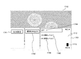
S304では、マイコン108は、S303でSDRの輝度範囲外になるとして特定された画像領域に対し、OSD部106によりゼブラ画像を合成させることによりゼブラ表示を行わせる。例えば、前述した図4(b)のUI画面421の例の場合、例えば画像領域413,414は、白飛びや黒つぶれせずに、ユーザが確認可能な状態であるとする。一方、図4(c)のUI画面421の例は、スライドバー422が「輝度:高」側にスライドされてSDRの輝度範囲が高輝度側に調整されたことで黒つぶれしてしまう画像領域に対して、ゼブラ画像423,424が表示された状態を示している。なお、図4(c)のUI画面421では、黒つぶれしてしまう特定の画像領域に対してゼブラ画像423,424を表示する例を挙げたが、白飛びする特定の画像領域に対してゼブラ画像を表示してもよいし、それら両方にゼブラ画像を表示してもよい。それら両方にゼブラ画像を表示するような場合、黒つぶれする特定の画像領域に表示するゼブラ画像と、白飛びする特定の画像領域に表示するゼブラ画像とは、それぞれ異なる画像にすることが望ましい。なお、図4(b)、図4(c)の例では、画像430はHDR画像となされているが、スライドバー422によるSDRの輝度範囲の調整に応じて、画像430の輝度を調整してもよい。   In S <b> 304, the microcomputer 108 causes the OSD unit 106 to synthesize a zebra image for the image area specified as being out of the SDR luminance range in S <b> 303, thereby causing zebra display to be performed. For example, in the case of the example of the UI screen 421 in FIG. 4B described above, it is assumed that the image areas 413 and 414 are in a state that can be confirmed by the user without being overexposed or undercut. On the other hand, an example of the UI screen 421 in FIG. 4C is an image area in which the slide bar 422 is slid to the “luminance: high” side and the luminance range of the SDR is adjusted to the high luminance side, resulting in blackout On the other hand, the zebra images 423 and 424 are displayed. In the UI screen 421 in FIG. 4C, an example in which the zebra images 423 and 424 are displayed for a specific image area that is blackened is given. Images may be displayed, or zebra images may be displayed on both of them. In the case where zebra images are displayed on both of them, it is desirable that the zebra image displayed in the specific image area to be blacked out and the zebra image displayed in the specific image area to be blown out are different from each other. In the example of FIGS. 4B and 4C, the image 430 is an HDR image, but the brightness of the image 430 is adjusted according to the adjustment of the SDR brightness range by the slide bar 422. Also good.

以下、図5(a)から図5(g)を参照して、前述したスライドバーの位置、スライドバーの位置に応じた輝度変換、スライドバーの位置に応じた輝度変換のための輝度変換テーブルについて説明する。ここでは、前述したように、SDRの輝度範囲を設定する際のスライドバーの位置が、スライドバーの下端部に対応した輝度値により表される例を挙げて説明する。   Hereinafter, referring to FIG. 5A to FIG. 5G, the above-described slide bar position, the luminance conversion according to the slide bar position, and the luminance conversion table for the luminance conversion according to the slide bar position. Will be described. Here, as described above, an example will be described in which the position of the slide bar when setting the SDR luminance range is represented by the luminance value corresponding to the lower end of the slide bar.

図5(a)は、スライドバーの下端部の位置と、HDRの輝度値との対応関係を表すグラフである。図5(a)では、スライドバーの下端部の位置(座標値)を「スライドバーの下限値」と表記し、スライドバーの下限値に対応したHDRの輝度値を「輝度変換前の画素下限値」と表記している。図5(a)に示すように、スライドバーの位置は、輝度変換前の画素値により表すことが可能となっている。   FIG. 5A is a graph showing the correspondence between the position of the lower end of the slide bar and the HDR luminance value. In FIG. 5A, the position (coordinate value) of the lower end portion of the slide bar is expressed as “lower limit value of the slide bar”, and the HDR luminance value corresponding to the lower limit value of the slide bar is expressed as “pixel lower limit before luminance conversion”. Value ”. As shown in FIG. 5A, the position of the slide bar can be expressed by a pixel value before luminance conversion.

ここで、本実施形態では、前述したように、輝度変換前のHDRの各画素値は0〜4095の値をとり得る一方で、輝度変換後のSDRの各画素値は0〜255までの値しかとることができない。このため、本実施形態における輝度変換テーブルは、0〜255の256の分解能を有するテーブルとなされている。また、本実施形態では、輝度変換テーブルは、前述したように、輝度変換前の画素値と輝度変換後の画素値との対応関係を表している。このため、輝度変換は、スライドバーの下限値(スライドバーの位置)に応じた輝度変換前の画素値から、輝度変換テーブルを用いて輝度変換後の画素値を求めるような処理となる。さらに、本実施形態では、スライドバーの位置により、輝度変換前の画素値の0〜4095の中のどこに重みを付けるかを決め、そのスライドバーの位置に応じた重み付けがなされた輝度変換テーブルを用いて、輝度変換を行うようになされている。なお、図5(a)の例では、スライドバーの下端部の位置(下限値)のみを挙げたが、スライドバーの上端部の位置(上限値)が用いられてもよい。また、スライドバーの下限値と上限値に基づいて、SDRの輝度範囲が設定されてもよい。この場合、HDR画像のうち、スライドバーの下限値に対応した輝度値より低い輝度となる特定の画像領域は、SDR画像では黒つぶれする画像領域になる。一方、HDR画像のうち、スライドバーの上限値に対応した輝度値より高い輝度となる特定の画像領域は、SDR画像では白飛びする画像領域となる。   In this embodiment, as described above, each HDR pixel value before luminance conversion can take a value from 0 to 4095, while each SDR pixel value after luminance conversion is a value from 0 to 255. It can only be taken. For this reason, the luminance conversion table in the present embodiment is a table having a resolution of 256 from 0 to 255. In this embodiment, as described above, the luminance conversion table represents the correspondence between the pixel value before luminance conversion and the pixel value after luminance conversion. For this reason, the luminance conversion is a process of obtaining a pixel value after luminance conversion using a luminance conversion table from a pixel value before luminance conversion corresponding to the lower limit value (slide bar position) of the slide bar. Furthermore, in the present embodiment, the position of the pixel value before luminance conversion is determined where the weight is to be applied depending on the position of the slide bar, and the luminance conversion table weighted according to the position of the slide bar is determined. And luminance conversion is performed. In the example of FIG. 5A, only the position (lower limit value) of the lower end portion of the slide bar is described, but the position (upper limit value) of the upper end portion of the slide bar may be used. Further, the SDR luminance range may be set based on the lower limit value and the upper limit value of the slide bar. In this case, in the HDR image, a specific image region having a luminance lower than the luminance value corresponding to the lower limit value of the slide bar is an image region that is blackened in the SDR image. On the other hand, in the HDR image, a specific image region having a luminance higher than the luminance value corresponding to the upper limit value of the slide bar is an image region that is overexposed in the SDR image.

図5(e)は、スライドバーの下端部の位置(下限値)がスライドレールの下端部にある場合に、輝度変換前の画素値の0〜4095のうち画素値が低い側(0〜2048)に重み付けされた輝度変換テーブルを示している。また、図5(b)は、図5(e)の輝度変換テーブルを用いた場合の輝度変換前の画素値と輝度変換後の画素値との対応関係を表すグラフである。図5(e)の輝度変換テーブルは、輝度変換前の画素値0〜2047については256の分解能による輝度変換を行って輝度変換後の画素値とし、輝度変換前の画素値2048〜4095については輝度変換後の画素値を全て255にするようなテーブルである。具体的には、図5(e)の輝度変換テーブルは、輝度変換前の画素値0〜2047については画素値が8上がるごとに輝度変換後の画素値を1上げ、輝度変換前の画素値2048以上については輝度変換後の画素値を全て255にするようなテーブルである。この輝度変換テーブルを用いて輝度変換を行った場合、輝度変換前の画素値2048〜4095から得られる輝度変換後の画素値は白飛びする値になるが、輝度変換前の画素値0〜2048から得られる輝度変換後の画素値は白飛びしない値になる。また、この輝度変換テーブルを用いて輝度変換を行った場合、輝度変換前の画素値0〜2048から得られる輝度変換後の画像は、前述の図2(b)に示したような輝度変換テーブルよりも高い解像度の画像となる。   FIG. 5E shows a lower pixel value (0 to 2048) of 0 to 4095 of the pixel value before luminance conversion when the position (lower limit value) of the lower end of the slide bar is at the lower end of the slide rail. ) Shows a weighted luminance conversion table. FIG. 5B is a graph showing the correspondence between the pixel value before luminance conversion and the pixel value after luminance conversion when the luminance conversion table of FIG. 5E is used. In the luminance conversion table of FIG. 5E, the pixel values 0 to 2047 before the luminance conversion are subjected to luminance conversion with a resolution of 256 to obtain the pixel values after the luminance conversion, and the pixel values 2048 to 4095 before the luminance conversion. This is a table in which all pixel values after luminance conversion are set to 255. Specifically, in the luminance conversion table of FIG. 5E, for pixel values 0 to 2047 before luminance conversion, the pixel value after luminance conversion is increased by 1 each time the pixel value increases by 8, and the pixel value before luminance conversion For 2048 and higher, all the pixel values after luminance conversion are set to 255. When luminance conversion is performed using this luminance conversion table, the pixel value after luminance conversion obtained from the pixel values 2048 to 4095 before luminance conversion is a white value, but the pixel value 0 to 2048 before luminance conversion is obtained. The pixel value after luminance conversion obtained from is a value that does not skip white. Further, when luminance conversion is performed using this luminance conversion table, an image after luminance conversion obtained from pixel values 0 to 2048 before luminance conversion is the luminance conversion table as shown in FIG. Higher resolution image.

図5(f)は、スライドバーがスライドレールの略々中央部にある場合に、輝度変換前の画素値0〜4095のうち1024〜3071までの画素値に重み付けされた輝度変換テーブルを示している。また、図5(c)は、図5(f)の輝度変換テーブルを用いた場合の輝度変換前の画素値と輝度変換後の画素値との対応関係を表すグラフである。図5(f)の輝度変換テーブルは、輝度変換前の画素値0〜1023は輝度変換後の画素値を0とし、輝度変換前の画素値1024〜3071は256の分解能で輝度変換し、輝度変換前の画素値3072以上は輝度変換後の画素値を255にするテーブルである。具体的には、図5(f)の輝度変換テーブルは、輝度変換前の画素値が1024〜3071では画素値が8上がるごとに輝度変換後の画素値が1上がるようなテーブルとなされている。一方、輝度変換前の画素値0〜1023では輝度変換後の画素値が全て0となり、輝度変換後の画素値が3072以上では全て255の画素値となるようなテーブルとなされている。この輝度変換テーブルを用いた輝度変換処理が行われた場合、輝度変換前の画素値0〜1023から得られる輝度変換後の画素値は黒つぶれする値になり、輝度変換前の画素値3072以上から得られる輝度変換簿の画素値は白飛びする値になる。一方、輝度変換後の画素値1024〜3071から得られる輝度変換後の画素値は黒つぶれも白飛びも発生しない値になる。また、この輝度変換テーブルを用いて輝度変換を行った場合、輝度変換前の画素値1024〜3071から得られる輝度変換後の画像は、前述の図2(b)に示したような輝度変換テーブルよりも高い解像度の画像となる。   FIG. 5F shows a luminance conversion table weighted to pixel values from 1024 to 3071 out of pixel values 0 to 4095 before luminance conversion when the slide bar is substantially at the center of the slide rail. Yes. FIG. 5C is a graph showing the correspondence between the pixel value before luminance conversion and the pixel value after luminance conversion when the luminance conversion table of FIG. 5F is used. In the luminance conversion table of FIG. 5F, pixel values 0 to 1023 before luminance conversion are set to 0 after luminance conversion, and pixel values 1024 to 3071 before luminance conversion are luminance-converted at a resolution of 256. The pixel value 3072 or higher before conversion is a table for setting the pixel value after luminance conversion to 255. Specifically, the luminance conversion table in FIG. 5F is a table in which the pixel value after luminance conversion increases by 1 every time the pixel value increases by 8 when the pixel value before luminance conversion is 1024 to 3071. . On the other hand, in the pixel values 0 to 1023 before the luminance conversion, all the pixel values after the luminance conversion are 0, and when the pixel values after the luminance conversion are 3072 or more, all the pixel values are 255. When the luminance conversion process using this luminance conversion table is performed, the pixel value after luminance conversion obtained from the pixel values 0 to 1023 before luminance conversion becomes a blackened value, and the pixel value before luminance conversion is 3072 or more. The pixel value of the luminance conversion book obtained from is a value that is overexposed. On the other hand, the pixel value after luminance conversion obtained from the pixel values 1024 to 3071 after luminance conversion is a value in which neither blackening nor whiteout occurs. In addition, when luminance conversion is performed using this luminance conversion table, an image after luminance conversion obtained from the pixel values 1024 to 3071 before luminance conversion is the luminance conversion table as shown in FIG. Higher resolution image.

図5(g)は、スライドバーの位置がスライドレールの一番上(スライドバーの上端部がスライドレールの上端部)にある場合、輝度変換前の画素値の0〜4095のうち画素値が高い側(2048〜4095)に重み付けされた輝度変換テーブルを示している。また、図5(d)は、図5(g)の輝度変換テーブルを用いた場合の輝度変換前の画素値と輝度変換後の画素値との対応関係を表すグラフである。図5(g)の輝度変換テーブルは、輝度変換前の画素値0〜2047は輝度変後の画素値を0とし、輝度変換前の画素値2048〜4095は256の分解能で輝度変換して輝度変換後の画素値とするようなテーブルである。具体的には、図5(g)の輝度変換テーブルは、輝度変換前の画素値0〜2047では輝度変換後の画素値が全て0となり、輝度変換前の画素値2048以上では画素値が8上がるごとに輝度変換後の画素値は1上がるようなテーブルである。この輝度変換テーブルを用いて輝度変換を行った場合、輝度変換前の画素値0〜2047から得られる輝度変換後の画素値は黒つぶれするが、輝度変換前の画素値2048〜4095から得られる輝度変換後の画像は、黒つぶれしない値となる。また、この輝度変換テーブルを用いて輝度変換を行った場合、輝度変換前の画素値2048〜4095から得られる輝度変換後の画像は、前述の図2(b)に示した輝度変換テーブルよりも高い解像度の画像となる。   In FIG. 5G, when the position of the slide bar is at the top of the slide rail (the upper end of the slide bar is the upper end of the slide rail), the pixel value of 0 to 4095 of the pixel value before luminance conversion is The luminance conversion table weighted to the high side (2048-4095) is shown. FIG. 5D is a graph showing the correspondence between the pixel value before luminance conversion and the pixel value after luminance conversion when the luminance conversion table of FIG. 5G is used. In the luminance conversion table of FIG. 5G, pixel values 0 to 2047 before luminance conversion are set to 0 after luminance change, and pixel values 2048 to 4095 before luminance conversion are luminance-converted with a resolution of 256. It is a table which makes it a pixel value after conversion. Specifically, in the luminance conversion table of FIG. 5G, the pixel values after luminance conversion are all 0 for pixel values 0 to 2047 before luminance conversion, and the pixel value is 8 for pixel values 2048 and higher before luminance conversion. This is a table in which the pixel value after luminance conversion increases by 1 each time it increases. When luminance conversion is performed using this luminance conversion table, pixel values after luminance conversion obtained from pixel values 0 to 2047 before luminance conversion are blacked out, but are obtained from pixel values 2048 to 4095 before luminance conversion. The image after luminance conversion has a value that does not cause blackening. In addition, when luminance conversion is performed using this luminance conversion table, the image after luminance conversion obtained from the pixel values 2048 to 4095 before luminance conversion is more than the luminance conversion table shown in FIG. High resolution image.

図3のフローチャートに説明を戻す。S304の後、マイコン108は、S305に処理を進める。S305では、マイコン108は、OSD部106を介して、HDR画像の中に、SDRの輝度範囲外となる画像領域が存在することをユーザに通知するための警告用の表示情報を液晶パネル107に表示させる。具体的には、マイコン108は、例えば図4(c)のUI画面421に例示しているような警告用のメッセージ425を表示させる。なお、ユーザに対する警告は、警告表示用メッセージ425の表示の他に、音声等により行われてもよい。S305の後、マイコン108は、図3のフローチャートの処理を終了する。   Returning to the flowchart of FIG. After S304, the microcomputer 108 proceeds to S305. In S305, the microcomputer 108 displays warning display information on the liquid crystal panel 107 for notifying the user that there is an image area outside the SDR luminance range in the HDR image via the OSD unit 106. Display. Specifically, the microcomputer 108 displays a warning message 425 as exemplified in the UI screen 421 of FIG. The warning for the user may be given by voice or the like in addition to the display of the warning display message 425. After S305, the microcomputer 108 ends the process of the flowchart of FIG.

以上説明したように、本実施形態によれば、ユーザは、HDR画像のデータがメモリカード113に記録される前に、その後HDR非対応表示装置で表示されることになった場合でも、意図した画像領域が黒つぶれや色飛びせずに表示されるか否かを確認できる。一例として、図4(c)のUI画面421の例でユーザが意図した画像領域が花火の画像領域であったとする。この場合、その後、HDR非対応表示装置に表示された場合には、少なくとも花火の画像領域が表示されればよいと考えられる。図4(c)の例の場合、ユーザが意図していない他の画像領域(例えば図4(c)でゼブラ画像423や424が表示された領域)については黒つぶれすることになるが、少なくとも花火の画像領域については黒つぶれ等することなく表示される。   As described above, according to the present embodiment, the user intended the HDR image data even before it was displayed on the non-HDR compatible display device before being recorded on the memory card 113. It can be confirmed whether or not the image area is displayed without being blacked out or skipped. As an example, it is assumed that the image region intended by the user in the example of the UI screen 421 in FIG. 4C is a firework image region. In this case, when it is displayed on the non-HDR compatible display device, it is considered that at least the image area of the fireworks should be displayed. In the case of the example of FIG. 4C, other image areas not intended by the user (for example, areas in which the zebra images 423 and 424 are displayed in FIG. 4C) are blackened, but at least The fireworks image area is displayed without being blacked out.

そして、本実施形態のカメラ100では、ユーザが意図した画像領域に対する確認が行われた画像をメモリカード113から読み出し、外部出力部115からHDR非対応表示装置に送って表示させる場合、ユーザの意図を反映させた輝度変換が行われる。このため、本実施形態のカメラ100は、メモリカード113にHDR画像データ(圧縮ビデオデータ)を記録する際には、前述したように、そのHDR画像データに関連付けるようにして輝度変換情報をも記録する。なお、本実施形態において、輝度変換情報は、ユーザが指定したSDRの輝度範囲に応じた輝度変換テーブルと、後述するダイナミックレンジ情報とを含む情報である。   In the camera 100 according to the present embodiment, when an image in which an image area intended by the user is confirmed is read from the memory card 113 and sent from the external output unit 115 to an HDR non-compliant display device for display, the user's intention The luminance conversion reflecting the above is performed. Therefore, when recording HDR image data (compressed video data) on the memory card 113, the camera 100 of this embodiment also records luminance conversion information so as to be associated with the HDR image data as described above. To do. In the present embodiment, the luminance conversion information is information including a luminance conversion table corresponding to the luminance range of the SDR specified by the user and dynamic range information described later.

図6は、本実施形態のカメラ100において、ユーザ指定のSDRの輝度範囲に応じた輝度変換テーブル等を含む輝度変換情報を生成して、HDR画像データと関連付けるようにしてメモリカード113に記録する場合の画像処理のフローチャートである。図6のフローチャートにおける各処理ステップは、カメラ100のマイコン108が、ROM110に保存されている本実施形態に係る画像処理プログラムを実行して各部を制御することにより実現される。なお、以下の説明では、図6の各処理ステップS601〜ステップS611を、S601〜S611と略記する。本実施形態のカメラ100において、画像の撮影がなされている場合、センサ102は動画のフレーム毎に撮像画像を取り込み、そのフレーム毎の撮像画像のデータが画像処理部103で処理されてRAM111に送られる。図6のフローチャートは、動画の撮影が開始されたことでスタートする。   FIG. 6 shows that the camera 100 according to the present embodiment generates brightness conversion information including a brightness conversion table corresponding to the brightness range of the SDR specified by the user, and records it on the memory card 113 so as to be associated with the HDR image data. It is a flowchart of the image processing in a case. Each processing step in the flowchart of FIG. 6 is realized by the microcomputer 108 of the camera 100 executing the image processing program according to the present embodiment stored in the ROM 110 to control each unit. In the following description, each processing step S601 to step S611 in FIG. 6 is abbreviated as S601 to S611. In the camera 100 of this embodiment, when an image is captured, the sensor 102 captures a captured image for each frame of the moving image, and the captured image data for each frame is processed by the image processing unit 103 and sent to the RAM 111. It is done. The flowchart in FIG. 6 starts when the shooting of a moving image is started.

図6のS601では、マイコン108は、撮影したHDR画像データをメモリカード113に記録する場合に、輝度変換テーブルの情報をHDR画像データに関連付けるようにしたメタデータとして記録する設定がオンになされているか否かを判断する。本実施形態の場合、ユーザは、操作スイッチ群109を介して、輝度変換テーブルの情報をメタデータとして記録する設定のオンやオフの指示を入力可能となされている。操作スイッチ群109を介したユーザからの各種指示入力情報は例えばROM110に記憶されている。したがって、マイコン108は、ROM110に保持された指示入力情報をみることにより、輝度変換テーブルをメタデータとして記録する設定がオンになされているか否かを判断する。マイコン108は、S601において、輝度変換テーブルをメタデータとして記録する設定がオンになされていると判定した場合にはS302に処理を進める。一方、マイコン108は、S601において、設定がオフ(無効)になされていると判断した場合には、後述するS604に処理を進める。   In S601 of FIG. 6, when recording the captured HDR image data in the memory card 113, the microcomputer 108 is set to record the metadata conversion table information as metadata that is associated with the HDR image data. Determine whether or not. In the case of the present embodiment, the user can input an instruction to turn on / off the setting for recording information of the luminance conversion table as metadata via the operation switch group 109. Various instruction input information from the user via the operation switch group 109 is stored in the ROM 110, for example. Therefore, the microcomputer 108 determines whether or not the setting for recording the luminance conversion table as metadata is turned on by looking at the instruction input information held in the ROM 110. If the microcomputer 108 determines in S601 that the setting for recording the luminance conversion table as metadata is turned on, the microcomputer 108 proceeds to S302. On the other hand, if the microcomputer 108 determines in S601 that the setting is off (invalid), the microcomputer 108 proceeds to S604 described later.

図7は、輝度変換テーブルをメタデータとして記録する設定を行う場合に例えば液晶パネル107に表示されるUI画面701の一例を示す図である。なお、図7は、マイコン108による制御の下で、OSD部106により各種メニュー画像がHDR画像に合成されて液晶パネル107等に表示された画面例である。図7のUI画面701には、センサ102から出力されて画像処理部103の画像処理を介してRAM111に一時記憶されたHDR画像データに基づくHDR画像710が表示されている。また、図7のUI画面701には、メモリカード113への記録設定を行うための記録設定メニュー741の下位メニューとして、メタデータ記録設定の際に用いられる標準DR(SDR)メタデータ記録メニュー742が表示される。さらに、このメタデータ記録メニュー742の下位メニューには、メタデータ記録を有効(ON)に設定する際に選択されるONメニュー743と、無効(OFF)に設定する際に選択されるOFFメニュー744とが用意されている。図7のUI画面701の例は、操作スイッチ群109の操作を介してユーザによりONメニュー743が選択されて、例えばハイライト表示されている状態を表している。   FIG. 7 is a diagram illustrating an example of a UI screen 701 displayed on, for example, the liquid crystal panel 107 when setting to record the luminance conversion table as metadata. FIG. 7 shows an example of a screen in which various menu images are combined with an HDR image by the OSD unit 106 and displayed on the liquid crystal panel 107 or the like under the control of the microcomputer 108. On the UI screen 701 in FIG. 7, an HDR image 710 based on the HDR image data output from the sensor 102 and temporarily stored in the RAM 111 through the image processing of the image processing unit 103 is displayed. In addition, the UI screen 701 in FIG. 7 includes a standard DR (SDR) metadata recording menu 742 used for metadata recording setting as a lower menu of the recording setting menu 741 for performing recording setting to the memory card 113. Is displayed. Further, the lower menu of the metadata recording menu 742 includes an ON menu 743 that is selected when the metadata recording is set to be valid (ON), and an OFF menu 744 that is selected when the metadata recording is set to be invalid (OFF). And are prepared. The example of the UI screen 701 in FIG. 7 represents a state in which the ON menu 743 is selected by the user through the operation of the operation switch group 109 and is highlighted, for example.

図6のフローチャートに説明を戻す。S302に進んだ場合、マイコン108は、操作スイッチ群109を介してユーザより入力された、SDRの輝度範囲の情報を取得する。このS302の処理は、前述した図3のS302の処理と同様であるため、ここではその詳細な説明については省略する。S302の後、マイコン108は、S602に処理を進める。   Returning to the flowchart of FIG. When the process proceeds to S <b> 302, the microcomputer 108 acquires information on the luminance range of the SDR input by the user via the operation switch group 109. Since the process of S302 is the same as the process of S302 of FIG. 3 described above, detailed description thereof is omitted here. After S302, the microcomputer 108 proceeds to S602.

S602では、マイコン108は、S302で取得したSDRの輝度範囲の情報に基づいて輝度情報生成部105が作成した輝度変換テーブルの情報をRAM111に記憶させる。このときの輝度変換テーブルは、前述の図5(a)〜図5(g)で説明したような、スライドバーの位置情報に応じて重み付けされた輝度変換テーブルであり、ここではその詳細な説明については省略する。S602の後、マイコン108は、S603に処理を進める。   In step S <b> 602, the microcomputer 108 causes the RAM 111 to store information on the luminance conversion table created by the luminance information generation unit 105 based on the information on the luminance range of the SDR acquired in step S <b> 302. The luminance conversion table at this time is a luminance conversion table weighted according to the position information of the slide bar as described with reference to FIGS. 5A to 5G, and the detailed description thereof will be given here. Is omitted. After S602, the microcomputer 108 proceeds to S603.

S603では、マイコン108は、カメラ100において画像の撮影がなされた際のダイナミックレンジ情報を、画像処理部103から取得し、RAM111に記憶させる。このときのダイナミックレンジ情報は、例えばSDRのダイナミックレンジを基準とし、その基準ダイナミックレンジに対する比率を示す情報であってもよい。比率が分かれば、撮影がなされた際のダイナミックレンジを、基準ダイナミックレンジから相対的に一意に決めることが可能となる。S603の後、マイコン108は、S604に処理を進める。   In step S <b> 603, the microcomputer 108 acquires dynamic range information when an image is captured by the camera 100 from the image processing unit 103 and stores the dynamic range information in the RAM 111. The dynamic range information at this time may be information indicating a ratio with respect to the reference dynamic range, for example, based on the SDR dynamic range. If the ratio is known, the dynamic range at the time of shooting can be determined relatively uniquely from the reference dynamic range. After S603, the microcomputer 108 proceeds to S604.

S604では、マイコン108は、操作スイッチ群109を介してユーザより、カメラ100に対して記録開始指示が入力されたか否かを判断する。マイコン108は、S604において、ユーザから操作スイッチ群109を介して記録開始指示が入力されたと判断した場合には、S605へ処理を進める。一方、マイコン108は、S604において、記録開始指示が入力されていないと判断した場合にはS601に処理を戻す。   In step S <b> 604, the microcomputer 108 determines whether a user has input a recording start instruction to the camera 100 via the operation switch group 109. If the microcomputer 108 determines in S604 that a recording start instruction has been input from the user via the operation switch group 109, the microcomputer 108 proceeds to S605. On the other hand, if the microcomputer 108 determines in S604 that a recording start instruction has not been input, the microcomputer 108 returns the process to S601.

S605に進むと、マイコン108は、画像処理部103からRAM111に送られて一時記憶されている1フレーム分の画像データを圧縮伸張回路104に出力させ、その画像データを圧縮伸張回路104により圧縮させる。そして、圧縮伸張回路104により圧縮された画像データは、1フレーム分の圧縮ビデオデータとして、RAM111のバッファ領域に書き込まれる。S605の後、マイコン108は、S606に処理を進める。   In step S <b> 605, the microcomputer 108 outputs one frame worth of image data sent from the image processing unit 103 to the RAM 111 and temporarily stored in the compression / decompression circuit 104, and causes the compression / decompression circuit 104 to compress the image data. . The image data compressed by the compression / decompression circuit 104 is written in the buffer area of the RAM 111 as compressed video data for one frame. After S605, the microcomputer 108 proceeds to S606.

S606では、マイコン108は、RAM111のバッファ領域を確認し、一定量の圧縮ビデオデータがたまっているか否かを判断する。マイコン108は、S606において、RAM111のバッファ領域に一定量の圧縮ビデオデータがたまっていると判断した場合には、S607に処理を進める。一方、マイコン108は、S606において、一定量の圧縮ビデオデータがたまっていないと判断した場合には、S608に処理を進める。   In S606, the microcomputer 108 confirms the buffer area of the RAM 111 and determines whether or not a certain amount of compressed video data is accumulated. If the microcomputer 108 determines in S606 that a certain amount of compressed video data has accumulated in the buffer area of the RAM 111, the process proceeds to S607. On the other hand, if the microcomputer 108 determines in S606 that a certain amount of compressed video data has not been accumulated, the microcomputer 108 proceeds to S608.

S607に進むと、マイコン108は、メモリカードコントローラ112を制御して、RAM111に保持されている圧縮ビデオデータをメモリカード113に書き込ませる。S607の後、マイコン108は、S608に処理を進める。   In step S <b> 607, the microcomputer 108 controls the memory card controller 112 to write the compressed video data held in the RAM 111 into the memory card 113. After S607, the microcomputer 108 proceeds to S608.

S608では、マイコン108は、操作スイッチ群109を介してユーザより、カメラ100に対して記録停止指示が入力されたか否かを判断する。マイコン108は、S608において、記録停止指示が入力されたと判断した場合にはS609に処理を進め、記録停止指示が入力されていないと判断した場合にはS605に処理を戻す。   In step S <b> 608, the microcomputer 108 determines whether a recording stop instruction is input to the camera 100 from the user via the operation switch group 109. If the microcomputer 108 determines in S608 that a recording stop instruction has been input, the microcomputer 108 proceeds to S609. If the microcomputer 108 determines that a recording stop instruction has not been input, the microcomputer 108 returns the process to S605.

S609では、マイコン108は、RAM111のバッファ領域を確認し、圧縮ビデオデータがたまっているか(残っているか)否かを判断する。マイコン108は、S609において、バッファにデータがたまっていると判断した場合にはS610に処理を進め、たまっていないと判断した場合にはS611に処理を進める。   In S609, the microcomputer 108 checks the buffer area of the RAM 111 and determines whether or not the compressed video data is accumulated (remains). If the microcomputer 108 determines in S609 that data has accumulated in the buffer, the microcomputer 108 proceeds to S610. If it determines that data has not accumulated, the microcomputer 108 proceeds to S611.

S610では、マイコン108は、メモリカードコントローラ112を制御して、RAM111に保持されている圧縮ビデオデータをメモリカード113に書き込ませる。S610の後、マイコン108は、S611に処理を進める。   In step S <b> 610, the microcomputer 108 controls the memory card controller 112 to write the compressed video data held in the RAM 111 to the memory card 113. After S610, the microcomputer 108 proceeds to S611.

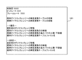
S611では、マイコン108は、圧縮ビデオデータの管理情報を生成して、RAM111上に一時的に記憶させた後、メモリカードコントローラ112を介してメモリカード113に書き込ませる。図8は、圧縮ビデオデータの管理情報801の一例を示す図である。管理情報801は、圧縮ビデオデータの画像サイズを示す解像度、圧縮ビデオデータのデータサイズを示すビットレート、圧縮ビデオデータのフレームレートを含む。また、本実施形態において、前述した輝度変換テーブルをメタデータとして記録する設定が有効(ON)であった場合には、RAM111に保持されている輝度変換情報はメタデータとして記録される。このため、管理情報801には、輝度変換テーブルの有無を示す情報、撮影時のダイナミックレンジ情報、輝度変換の際の前述した分解能の情報、輝度変換テーブルのファイル名等が含まれる。なお、輝度変換テーブルの有無と記録される画像データとを関連付ける必要があるため、輝度変換テーブルのファイル名は、動画や音声のデータと同じファイル名となされる。S611の後、マイコン108は、この図6のフローチャートの処理を終了する。   In S <b> 611, the microcomputer 108 generates compressed video data management information, temporarily stores it in the RAM 111, and then writes the management information to the memory card 113 via the memory card controller 112. FIG. 8 shows an example of management information 801 for compressed video data. The management information 801 includes a resolution indicating the image size of the compressed video data, a bit rate indicating the data size of the compressed video data, and a frame rate of the compressed video data. In the present embodiment, when the setting for recording the above-described luminance conversion table as metadata is valid (ON), the luminance conversion information stored in the RAM 111 is recorded as metadata. Therefore, the management information 801 includes information indicating the presence / absence of a luminance conversion table, dynamic range information at the time of photographing, information on the resolution at the time of luminance conversion, a file name of the luminance conversion table, and the like. Since it is necessary to associate the presence / absence of the luminance conversion table with the recorded image data, the file name of the luminance conversion table is the same as that of the moving image or audio data. After S611, the microcomputer 108 ends the processing of the flowchart of FIG.

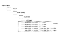
図9には、メモリカード113に記録される画像データのフォルダ構成例を示す。なお、図9は、操作スイッチ群109を介してユーザより記録開始指示と記録終了指示の入力がなされた後のフォルダとファイルの構成を表している。図9に示すように、マイコン108は、メモリカード113のルート上に、CONTENSフォルダ、そのフォルダ内にCLIPS001のフォルダを生成する。CLIPS001のフォルダ内には、カメラ100のメニュー設定に関連する情報や、INDEX.MIF、MXFファイル、XMLファイル、CPFファイルが含まれる。INDEX.MIFは、図8の管理情報801を管理するためのファイルである。MXFファイルは、動画や音声データが記録されているファイルである。XML(ExtensibeMarkupLanguage)ファイルは、クリップに関する情報を管理しているファイルである。CPF(CustomPictureFile)ファイルは、カメラ100のカメラ信号処理に関係する設定値を管理しているファイルである。そして、マイコン108は、輝度変換テーブル902を、動画や音声データと同一のファイル名で記録する。   FIG. 9 shows a folder configuration example of image data recorded on the memory card 113. FIG. 9 shows the structure of folders and files after a recording start instruction and a recording end instruction are input from the user via the operation switch group 109. As shown in FIG. 9, the microcomputer 108 generates a CONTENTS folder on the route of the memory card 113 and a CLIPS001 folder in the folder. In the CLIPS001 folder, information related to the menu setting of the camera 100, INDEX. MIF, MXF file, XML file, and CPF file are included. INDEX. The MIF is a file for managing the management information 801 in FIG. The MXF file is a file in which moving images and audio data are recorded. An XML (Extensible Markup Language) file is a file that manages information about clips. A CPF (Custom Picture File) file is a file that manages setting values related to camera signal processing of the camera 100. Then, the microcomputer 108 records the luminance conversion table 902 with the same file name as the moving image or audio data.

図10は、本実施形態のカメラ100が再生モードになされた場合において、前述したように画像データに輝度変換情報がメタデータとして記録されたメモリカード113から、画像データを読み出して再生する場合のフローチャートである。図10のフローチャートにおける各処理ステップは、カメラ100のマイコン108が、ROM110に保存されている本実施形態に係る画像処理プログラムを実行して各部を制御することにより実現される。なお、以下の説明では、図10の各処理ステップS1001〜ステップS1009を、S1001〜S1009と略記する。本実施形態において、図10のフローチャートは、カメラ100が再生モードに遷移して、メモリカード113から画像データの読み出しが可能な状態になったときにスタートする。   FIG. 10 shows a case where the image data is read out and reproduced from the memory card 113 in which the luminance conversion information is recorded as metadata in the image data as described above when the camera 100 of the present embodiment is in the reproduction mode. It is a flowchart. Each processing step in the flowchart of FIG. 10 is realized by the microcomputer 108 of the camera 100 executing the image processing program according to the present embodiment stored in the ROM 110 to control each unit. In the following description, the processing steps S1001 to S1009 in FIG. 10 are abbreviated as S1001 to S1009. In the present embodiment, the flowchart of FIG. 10 starts when the camera 100 transitions to the playback mode and image data can be read from the memory card 113.

図10のS1001では、マイコン108は、操作スイッチ群109を介してユーザより、カメラ100に対して再生開始指示が入力されたか否かを判断する。マイコン108は、S1001において、再生開始指示が入力されたと判断した場合にはS1002に処理を進め、再生開始指示が入力されていないと判断した場合にはS1001の判断に戻る。   In S <b> 1001 of FIG. 10, the microcomputer 108 determines whether or not a reproduction start instruction is input to the camera 100 from the user via the operation switch group 109. If the microcomputer 108 determines in S1001 that the reproduction start instruction has been input, the microcomputer 108 proceeds to S1002, and if it determines that the reproduction start instruction has not been input, the microcomputer 108 returns to the determination in S1001.

S1002では、マイコン108は、ユーザより再生開始指示を受けたクリップの管理情報を読み出すための指示を、メモリカードコントローラ112に行い、その指示に応じてメモリカード113から読み出された管理情報をRAM111に展開する。S1002の後、マイコン108は、S1003に処理を進める。   In step S <b> 1002, the microcomputer 108 instructs the memory card controller 112 to read the management information of the clip that has received a playback start instruction from the user, and the management information read from the memory card 113 according to the instruction is stored in the RAM 111. Expand to. After S1002, the microcomputer 108 proceeds to S1003.

S1003では、マイコン108は、S1002でRAM111に展開された管理情報を解析し、再生対象のクリップに対する管理情報を取得する。S1003の後、マイコン108は、S1004に処理を進める。   In S1003, the microcomputer 108 analyzes the management information expanded in the RAM 111 in S1002, and acquires management information for the clip to be played back. After S1003, the microcomputer 108 proceeds to S1004.

S1004では、マイコン108は、操作スイッチ群109を介してユーザより、メモリカード113から読み出された画像データを例えば外部出力部115から出力するときに、SDRへの輝度変換が有効と無効の何れに設定されているかを判断する。マイコン108は、S1004において、SDRへの輝度変換が有効に設定されていると判断した場合にはS1005に処理を進め、一方、無効に設定されていると判断した場合にはS1008に処理を進める。   In S1004, when the microcomputer 108 outputs the image data read from the memory card 113 from the user via the operation switch group 109, for example, from the external output unit 115, whether the luminance conversion to SDR is valid or invalid. Determine whether it is set to. If the microcomputer 108 determines in S1004 that the luminance conversion to SDR is enabled, the microcomputer 108 proceeds to S1005. If the microcomputer 108 determines that the luminance conversion is disabled, the microcomputer 108 proceeds to S1008. .

図11(a)は、メモリカード113から読み出された画像データを外部出力部115から出力するときにSDRへの輝度変換を有効又は無効に設定する場合に、例えば液晶パネル107に表示されるUI画面1101の一例を示す図である。なお、図11(a)は、マイコン108による制御の下で、OSD部106により各種メニュー画像がHDR画像に合成されて液晶パネル107等に表示された画面例である。図11(a)のUI画面1101には、メモリカード113から読み出されて圧縮伸張回路104にて伸張された画像データに基づく画像1110が表示されている。また、図11(a)のUI画面1101には、外部出力部115を介した画像出力を行う場合にSDRへ輝度変換して出力する際の出力設定メニュー1141の下位メニューとして、標準DR(SDR)出力メニュー1142が表示される。さらに、この出力メニュー1142の下位メニューには、SDRへ輝度変換した出力を有効(ON)に設定する際に選択されるONメニュー1143と、無効(OFF)に設定する際に選択されるOFFメニュー1144とが用意されている。図11(a)のUI画面1101の例は、操作スイッチ群109の操作を介してユーザによりONメニュー1143が選択されて、例えばハイライト表示されている状態を表している。   FIG. 11A is displayed on the liquid crystal panel 107, for example, when the luminance conversion to SDR is set to be valid or invalid when the image data read from the memory card 113 is output from the external output unit 115. 5 is a diagram illustrating an example of a UI screen 1101. FIG. FIG. 11A shows an example of a screen in which various menu images are combined with an HDR image by the OSD unit 106 and displayed on the liquid crystal panel 107 or the like under the control of the microcomputer 108. In the UI screen 1101 in FIG. 11A, an image 1110 based on image data read from the memory card 113 and decompressed by the compression / decompression circuit 104 is displayed. In addition, the UI screen 1101 in FIG. 11A has a standard DR (SDR) as a lower menu of the output setting menu 1141 when the luminance is converted to SDR when the image is output via the external output unit 115. ) The output menu 1142 is displayed. Further, the lower menu of the output menu 1142 includes an ON menu 1143 that is selected when the output converted to luminance to SDR is set to valid (ON), and an OFF menu that is selected when set to invalid (OFF). 1144 are prepared. The example of the UI screen 1101 in FIG. 11A shows a state in which the ON menu 1143 is selected by the user through the operation of the operation switch group 109 and is highlighted, for example.

図10のフローチャートに説明を戻す。S1005に進んだ場合、マイコン108は、RAM111に保持されている管理情報を見て、輝度変換のための輝度変換情報が存在し、且つその輝度変換情報の輝度変換テーブルが含まれているか否かを判断する。マイコン108は、S1005において、再生出力する画像データに関連した輝度変換テーブルが含まれていると判断した場合にはS1006に処理を進める。一方、マイコン108は、S1005において、輝度変換テーブルが含まれていないと判断した場合には、輝度変換テーブルに基づく輝度変換が行えないため、S1008に処理を進める。   Returning to the flowchart of FIG. When the process proceeds to S1005, the microcomputer 108 looks at the management information held in the RAM 111, and determines whether or not the brightness conversion information for brightness conversion exists and the brightness conversion table of the brightness conversion information is included. Judging. If the microcomputer 108 determines in S1005 that the luminance conversion table related to the image data to be reproduced and output is included, the microcomputer 108 proceeds to S1006. On the other hand, if the microcomputer 108 determines in S1005 that the luminance conversion table is not included, the microcomputer 108 proceeds to S1008 because luminance conversion based on the luminance conversion table cannot be performed.

S1008の処理に進んだ場合、マイコン108は、メモリカードコントローラ112に指示を出し、メモリカード113から所望の画像データを読み出し、RAM111に展開する。そして、マイコン108は、RAM111に展開された画像データを圧縮伸張回路104に送ってデコードさせ、そのデコードされた画像データをRAM111に展開する。さらに、マイコン108は、RAM111に展開された画像データを、液晶パネル107や外部出力部115に送る。   When the processing proceeds to S1008, the microcomputer 108 instructs the memory card controller 112 to read out desired image data from the memory card 113 and develop it in the RAM 111. Then, the microcomputer 108 sends the image data expanded in the RAM 111 to the compression / decompression circuit 104 for decoding, and expands the decoded image data in the RAM 111. Further, the microcomputer 108 sends the image data expanded in the RAM 111 to the liquid crystal panel 107 and the external output unit 115.

一方、S1006に進んだ場合、マイコン108は、RAM111に記憶されている管理情報を元に、メモリカードコントローラ112に指示を出し、メモリカード113から画像データと同じファイル名の輝度変換テーブルの情報を読み出す。そして、マイコン108は、その輝度変換テーブルをRAM111に展開した後、S1007に処理を進める。   On the other hand, when the processing proceeds to S1006, the microcomputer 108 instructs the memory card controller 112 based on the management information stored in the RAM 111, and obtains information on the luminance conversion table having the same file name as the image data from the memory card 113. read out. The microcomputer 108 expands the luminance conversion table in the RAM 111, and then advances the process to S1007.

S1007では、マイコン108は、メモリカードコントローラ112に指示を出し、メモリカード113から所望の画像データを読み出し、RAM111に展開する。そして、マイコン108は、RAM111に展開された画像データを、圧縮伸張回路104に送って伸張(デコード)を行わせ、そのデコードされた画像データをRAM111に展開する。さらに、マイコン108は、その画像データとS1006で読み込んだ輝度変換テーブルを、輝度変換部114に送って、輝度変換部114にてHDR画像データをSDR画像に輝度変換させ、その後YCrCbのSDR画像データを外部出力部115に送る。   In step S <b> 1007, the microcomputer 108 instructs the memory card controller 112 to read out desired image data from the memory card 113 and develop it in the RAM 111. Then, the microcomputer 108 sends the image data expanded in the RAM 111 to the compression / decompression circuit 104 for expansion (decoding), and expands the decoded image data in the RAM 111. Further, the microcomputer 108 sends the image data and the luminance conversion table read in S1006 to the luminance conversion unit 114, where the luminance conversion unit 114 converts the HDR image data into an SDR image, and then the YCRCb SDR image data. Is sent to the external output unit 115.

ここで、前述した図4(c)で例示したようにSDRの輝度範囲が高めに設定され、そのSDRの輝度範囲に応じた輝度変換テーブルに基づいて輝度変換されたSDR画像データが外部出力部115から出力されてHDR非対応表示装置に送られたとする。この場合、HDR非対応表示装置では、例えば図11(b)に示すような輝度の低い画像領域1103や1104は黒につぶれした状態で表示されることになる。なお、HDRに対応した液晶パネル107であれば、図11(c)に示すように黒つぶれのない画像領域1113,1114が表示されることになる。一方、撮影画像を記録する前に図4(c)のUI画面421でユーザが意図した画像領域が、例えば花火の画像領域であった場合、HDR非対応表示装置では、図11(b)のように、少なくとも花火の画像領域については黒つぶれ等せずに表示される。   Here, as exemplified in FIG. 4C described above, the SDR image data in which the luminance range of the SDR is set higher and the luminance is converted based on the luminance conversion table corresponding to the luminance range of the SDR is output to the external output unit. Suppose that it is output from 115 and sent to a display device that does not support HDR. In this case, in the non-HDR compatible display device, for example, the low-brightness image areas 1103 and 1104 as shown in FIG. In the case of the liquid crystal panel 107 corresponding to HDR, as shown in FIG. 11C, image areas 1113 and 1114 having no blackout are displayed. On the other hand, if the image area intended by the user on the UI screen 421 in FIG. 4C before recording the captured image is, for example, a fireworks image area, the HDR non-compliant display device in FIG. As described above, at least the image area of the fireworks is displayed without being blacked out.

図10のフローチャートに説明を戻す。S1007の後、マイコン108は、S1009に処理を進める。S1009では、マイコン108は、操作スイッチ群109を介してユーザより、再生終了の指示が入力されたか否か、または、圧縮伸張回路104から再生中の動画の画像データが最終位置(最後のフレーム)のデータになったか否かを判定する。マイコン108は、S1009において、再生終了の指示が入力されたと判断した場合、または、動画の画像データが最終位置のデータになったと判断した場合には、図10のフローチャートの処理を終了する。一方、マイコン108は、S1009において、再生終了の指示が入力されていない場合、または、動画の画像データが最終位置のデータになっていない場合には、S1004に処理を戻す。   Returning to the flowchart of FIG. After S1007, the microcomputer 108 proceeds to S1009. In step S <b> 1009, the microcomputer 108 determines whether or not a reproduction end instruction is input from the user via the operation switch group 109, or the image data of the moving image being reproduced from the compression / decompression circuit 104 is the final position (last frame). It is determined whether or not the data has become. If the microcomputer 108 determines in S1009 that an instruction to end reproduction has been input, or if it determines that the image data of the moving image has become the final position data, the microcomputer 108 ends the processing of the flowchart of FIG. On the other hand, the microcomputer 108 returns the process to S1004 when the instruction to end the reproduction is not input in S1009 or when the image data of the moving image is not the final position data.

以上説明したように、本実施形態の場合、撮影されたHDR画像データをメモリカード113に記録する前に、前述した図4(c)のように黒つぶれや白飛びしてしまう特定の画像領域にゼブラ画像423,424を表示することでユーザに通知する。そして、本実施形態の場合、撮影されたHDR画像データをメモリカード113に記録する前に、ユーザが意図した画像領域が黒つぶれや白飛びしないようにSDRの輝度範囲の調整が可能となされている。また、SDRの輝度範囲が調整された場合、それに応じた輝度変換テーブルが、輝度変換情報として画像データに関連付けてメモリカード113に記録される。したがって、メモリカード113から読み出した画像データを、その輝度変換テーブルを用いて輝度変換した後の画像データは、図11(b)のように、ユーザが意図した例えば花火の画像領域については黒つぶれや白飛びしない状態で表示される。このため、外部出力部115から出力された画像データが、HDR非対応表示装置に表示された場合、その画像データが記録された際に意図された画像領域がどのような画像であったかを、HDR非対応表示装置のユーザは確認することができる。このように、本実施形態では、画像撮影がなされた際に、ユーザが意図した画像領域が表示されるようなSDRの輝度範囲を指定可能となされている。このため、本実施形態によれば、その後の再生時に外部表示装置がHDR対応しているか否かによらず、外部表示装置のユーザは、カメラ100のユーザが意図した画像領域の画像を確認可能となっている。   As described above, in the case of the present embodiment, before recording the captured HDR image data on the memory card 113, a specific image area that is blacked out or blown out as shown in FIG. The user is notified by displaying zebra images 423 and 424. In the case of this embodiment, before recording the captured HDR image data on the memory card 113, the brightness range of the SDR can be adjusted so that the image area intended by the user is not crushed or blown out white. Yes. When the SDR luminance range is adjusted, a luminance conversion table corresponding to the SDR luminance range is recorded in the memory card 113 in association with image data as luminance conversion information. Therefore, the image data obtained by converting the luminance of the image data read from the memory card 113 using the luminance conversion table is blackened for the image area of the fireworks intended by the user as shown in FIG. It is displayed in a state where no whiteout occurs. For this reason, when the image data output from the external output unit 115 is displayed on an HDR non-compliant display device, it is possible to determine what kind of image the intended image area was when the image data was recorded. The user of the non-compatible display device can confirm. As described above, in this embodiment, it is possible to specify an SDR luminance range in which an image region intended by the user is displayed when an image is taken. Therefore, according to the present embodiment, the user of the external display device can check the image in the image region intended by the user of the camera 100 regardless of whether or not the external display device is HDR compatible during subsequent playback. It has become.

<第2実施形態>
図12は、第2実施形態に係る画像処理装置の一適用例であるカメラ1200の概略的な内部構成例を示す図である。第2実施形態のカメラ1200は、前述した図1のカメラ100と比較して、メモリカード、メモリカードコントローラ、輝度情報生成部が、それぞれA,B二つずつ設けられていることが異なっている。図12の例では、メモリカードA,Bをメモリカード113A,113B、メモリカードコントローラA,Bをメモリカードコントローラ112A,112B、輝度情報生成部A,Bを輝度情報生成部105A,105Bとして示している。メモリカード113A、メモリカードコントローラ112A、輝度情報生成部105Aは、それぞれ前述した図1のメモリカード113、メモリカードコントローラ112、輝度情報生成部105と同様のものである。メモリカード113B、メモリカードコントローラ112Bについても、図1のメモリカード113、メモリカードコントローラ112と同様のものである。ただし、メモリカードコントローラ112Bは、メモリカード113Bに対するデータの書き込みと読み出しを行うためのものである。また、輝度情報生成部105Bについても、輝度情報生成部105Aと同様のものである。なお、第2実施形態のカメラ1200において、メモリカード113A,113B、メモリカードコントローラ112A,112B、輝度情報生成部105A,105B以外の他の構成部分は図1と同じであるためそれらの説明は省略する。また、第2実施形態において、第1実施形態と同様のフローチャートについても説明は省略する。
Second Embodiment
FIG. 12 is a diagram illustrating a schematic internal configuration example of a camera 1200 which is an application example of the image processing apparatus according to the second embodiment. The camera 1200 of the second embodiment is different from the camera 100 of FIG. 1 described above in that two memory cards, two memory card controllers, and two luminance information generation units are provided. . In the example of FIG. 12, the memory cards A and B are shown as memory cards 113A and 113B, the memory card controllers A and B are shown as memory card controllers 112A and 112B, and the luminance information generators A and B are shown as luminance information generators 105A and 105B. Yes. The memory card 113A, the memory card controller 112A, and the luminance information generation unit 105A are the same as the memory card 113, the memory card controller 112, and the luminance information generation unit 105 of FIG. The memory card 113B and the memory card controller 112B are the same as the memory card 113 and the memory card controller 112 in FIG. However, the memory card controller 112B is for writing and reading data to and from the memory card 113B. The luminance information generation unit 105B is the same as the luminance information generation unit 105A. In the camera 1200 of the second embodiment, the other components other than the memory cards 113A and 113B, the memory card controllers 112A and 112B, and the luminance information generators 105A and 105B are the same as those in FIG. To do. In the second embodiment, the description of the same flowchart as that of the first embodiment is also omitted.

第2実施形態において、マイコン108は、輝度情報生成部105Bにより生成された輝度変換情報を、メモリカードコントローラ112Bに指示することによりメモリカード113Bに画像データと関連付けて記録させる。また、マイコン108は、操作スイッチ群109を介してユーザにより指定されたSDRの輝度範囲外となる特定の画像領域については、第1実施形態の例と同様に、OSD部106を介してゼブラ表示させる。   In the second embodiment, the microcomputer 108 instructs the memory card controller 112B to record the luminance conversion information generated by the luminance information generation unit 105B in association with the image data. Further, the microcomputer 108 displays a zebra display via the OSD unit 106 for a specific image area that is outside the luminance range of the SDR specified by the user via the operation switch group 109, as in the first embodiment. Let

図13(a)は、第2実施形態において、ユーザが操作スイッチ群109を操作してゼブラ表示を有効又は無効に設定する際のUI画面1301の一例を示す。図13(a)のUI画面1301には、センサ102から出力されて画像処理部103の画像処理を介してRAM111に一時記憶されたHDR画像データに基づくHDR画像1330が表示されている。また、図13(a)のUI画面1301には、液晶パネル107の表示設定を行うパネル設定メニュー1341の下位メニューとして、ゼブラ表示の設定の際に用いられる輝度範囲外ゼブラ表示メニュー1342が表示される。さらに、このメニュー1342の下位メニューには、ゼブラ表示を有効(ON)又は無効(OFF)に設定する際に選択されるメニューが用意されている。ただし、第2実施形態のカメラ1200の場合、二つのメモリカード113A,113Bがある。このため、ゼブラ表示を有効に設定するメニューは、メモリカード113A,113Bをそれぞれ個別に有効に設定するONメニュー1343,1344と、メモリカード113A,113Bの両方を有効に設定するONメニュー1345が用意されている。また、ゼブラ表示を無効に設定するメニューとしては、OFFメニュー1346が用意されている。図13(a)のUI画面1301の例は、操作スイッチ群109の操作を介してユーザによりONメニュー1345が選択されて、例えばハイライト表示されている状態を表している。   FIG. 13A illustrates an example of a UI screen 1301 when the user operates the operation switch group 109 to enable or disable the zebra display in the second embodiment. In the UI screen 1301 in FIG. 13A, an HDR image 1330 based on the HDR image data output from the sensor 102 and temporarily stored in the RAM 111 through the image processing of the image processing unit 103 is displayed. In addition, on the UI screen 1301 of FIG. 13A, a zebra display menu 1342 outside the luminance range used when setting the zebra display is displayed as a lower menu of the panel setting menu 1341 for setting the display of the liquid crystal panel 107. The Further, a menu that is selected when the zebra display is set to valid (ON) or invalid (OFF) is prepared as a lower menu of the menu 1342. However, in the case of the camera 1200 of the second embodiment, there are two memory cards 113A and 113B. For this reason, menus for enabling zebra display are prepared as ON menus 1343 and 1344 for individually enabling memory cards 113A and 113B and ON menu 1345 for enabling both memory cards 113A and 113B, respectively. Has been. An OFF menu 1346 is prepared as a menu for setting the zebra display to be invalid. The example of the UI screen 1301 in FIG. 13A represents a state in which the ON menu 1345 is selected by the user through the operation of the operation switch group 109 and is highlighted, for example.

図13(b)は、メモリカード113Aに対するゼブラ表示が有効に設定されている場合において、ユーザが操作スイッチ群109を操作してSDRの輝度範囲を指定する際のUI画面1302の例を示している。図13(b)のUI画面1302は、前述の図4(c)で説明したUI画面421と同様の例であり、前述したようなスライドバー422とスライドレール415が表示されている。ただし、図13(b)の例の場合、メモリカード113Aに対するUI画面1302であることをユーザが認識できるように、メモリカード113Aを表す例えばCardA1303が表示されている。   FIG. 13B shows an example of the UI screen 1302 when the user operates the operation switch group 109 to specify the luminance range of SDR when the zebra display for the memory card 113A is set to be valid. Yes. The UI screen 1302 in FIG. 13B is an example similar to the UI screen 421 described with reference to FIG. 4C, and displays the slide bar 422 and the slide rail 415 as described above. However, in the example of FIG. 13B, for example, CardA 1303 representing the memory card 113A is displayed so that the user can recognize that the UI screen 1302 is for the memory card 113A.

図13(c)は、メモリカード113Bに対するゼブラ表示が有効に設定されている場合において、ユーザが操作スイッチ群109を操作してSDRの輝度範囲を指定する際のUI画面1304の例を示している。図13(c)のUI画面1304についても図13(b)と同様のスライドバー422とスライドレール415が表示されている。また、図13(c)の場合、メモリカード113Bに対するUI画面1304であることをユーザが認識できるように、メモリカード113Bを表す例えばCardB1307が表示されている。ただし、図13(c)のUI画面1304の場合、ユーザが図13(b)のUI画面1302と区別できるように、ゼブラ画像の種別が図13(c)のゼブラ画像1305,1306のように、図13(b)のゼブラ画像423,424とは異なっている。一例として、図13(b)のゼブラ画像423,424は右上がりのゼブラ画像となされているのに対し、図13(c)のゼブラ画像1305,1306は右下がりのゼブラ画像となされている。   FIG. 13C shows an example of the UI screen 1304 when the user operates the operation switch group 109 to specify the luminance range of SDR when the zebra display for the memory card 113B is set to be valid. Yes. A slide bar 422 and a slide rail 415 similar to those in FIG. 13B are also displayed on the UI screen 1304 in FIG. In the case of FIG. 13C, for example, CardB 1307 representing the memory card 113B is displayed so that the user can recognize that it is the UI screen 1304 for the memory card 113B. However, in the case of the UI screen 1304 in FIG. 13C, the zebra image type is the zebra images 1305 and 1306 in FIG. 13C so that the user can distinguish from the UI screen 1302 in FIG. This is different from the zebra images 423 and 424 in FIG. As an example, zebra images 423 and 424 in FIG. 13B are zebra images that rise to the right, whereas zebra images 1305 and 1306 in FIG. 13C are zebra images that fall to the right.

第2実施形態のカメラ1200において、輝度変換情報を生成し、HDR画像データと関連付けるようにしてメモリカード113A,113Bに記録する場合の画像処理のフローチャートについて、前述した図6を用いて説明する。ここでは、前述の図6とは異なる処理のみ説明する。   A flow chart of image processing in the case where the camera 1200 of the second embodiment generates luminance conversion information and records it on the memory cards 113A and 113B so as to be associated with the HDR image data will be described with reference to FIG. Here, only processing different from the above-described FIG. 6 will be described.

図6のS611では、マイコン108は、画像データの圧縮ビデオデータの管理情報を生成して、RAM111上に一時的に記憶させる。第2実施形態の場合、マイコン108は、RAM111に記憶させた管理情報を、メモリカードコントローラ112Aを介してメモリカード113Aに書き込ませ、メモリカードコントローラ112Bを介してメモリカード113Bに書き込ませる。   In S <b> 611 of FIG. 6, the microcomputer 108 generates management information of compressed video data of image data and temporarily stores it on the RAM 111. In the case of the second embodiment, the microcomputer 108 causes the management information stored in the RAM 111 to be written to the memory card 113A via the memory card controller 112A and is written to the memory card 113B via the memory card controller 112B.

図14は、第2実施形態における圧縮ビデオデータの管理情報1401の一例を示す図である。なお、図14の管理情報1401は、図13(a)のONメニュー1345によりメモリカード113A,113Bの両方が有効に設定されている場合の例を挙げている。このように、メモリカード113A,113Bの両方が有効に設定されている場合、メモリカード113A,113Bには同時に画像データが記録される。管理情報1401は、前述した図8の管理情報801と同様に、圧縮ビデオデータの画像サイズを示す解像度、圧縮ビデオデータのデータサイズを示すビットレート、圧縮ビデオデータのフレームレートを含む。また、管理情報1401には、RAM111に保持されている輝度変換情報がメタデータとして含められる。ただし、第2実施形態の場合、異なる重み付けの輝度変換テーブルをメタデータとして記録可能となされている。このため、管理情報1401には、輝度変換テーブルの有無を示す情報の他に、輝度変換テーブルの個数の情報も含まれる。図14の管理情報1401の例では、1個目と2個目の二つの輝度変換テーブルの情報があり、それぞれについて、撮影時のダイナミックレンジ情報、輝度変換の際の分解能の情報、輝度変換の重み付けの情報、輝度変換テーブルのファイル名等が含まれている。このように第2実施形態では、それぞれ異なる重み付けの輝度変換テーブルを記録しておくことで、複数の輝度変換テーブルを用いた輝度変換が可能となり、それぞれ輝度が異なるSDR画像の表示が可能となる。この例のように、メモリカード113A,113Bに同時に画像データを記録した場合、ユーザよって使用する輝度変換テーブルが異なる場合があるため、メモリカード113A,113Bのどちらも同じメタデータ、複数の輝度変換テーブルファイルの記録を行う。   FIG. 14 is a diagram showing an example of compressed video data management information 1401 in the second embodiment. Note that the management information 1401 in FIG. 14 is an example in which both the memory cards 113A and 113B are enabled by the ON menu 1345 in FIG. As described above, when both the memory cards 113A and 113B are set to be valid, image data is simultaneously recorded on the memory cards 113A and 113B. The management information 1401 includes the resolution indicating the image size of the compressed video data, the bit rate indicating the data size of the compressed video data, and the frame rate of the compressed video data, as with the management information 801 of FIG. Further, the management information 1401 includes luminance conversion information held in the RAM 111 as metadata. However, in the case of the second embodiment, a luminance conversion table with different weights can be recorded as metadata. Therefore, the management information 1401 includes information on the number of luminance conversion tables in addition to the information indicating the presence / absence of the luminance conversion table. In the example of the management information 1401 in FIG. 14, there are information of two luminance conversion tables of the first and second, and for each, dynamic range information at the time of photographing, resolution information at the time of luminance conversion, luminance conversion information Information on weighting, file name of luminance conversion table, and the like are included. As described above, in the second embodiment, by recording luminance conversion tables with different weights, it is possible to perform luminance conversion using a plurality of luminance conversion tables and display SDR images having different luminances. . As in this example, when image data is simultaneously recorded on the memory cards 113A and 113B, the brightness conversion table used by the user may differ, so both the memory cards 113A and 113B have the same metadata and multiple brightness conversions. Record the table file.

図15は、前述のようにメモリカード113A,113Bに同時に記録される画像データのフォルダ構成例を示す。図15は、前述の図9の例と同様に、操作スイッチ群109を介してユーザより記録開始指示と記録終了指示の入力がなされた後のフォルダとファイルの構成を表している。ただし、図15に示すように、例えば二つの輝度変換テーブルが記録される場合、マイコン108は、それら輝度変換テーブル1502,1503を動画や音声データと同一のファイル名で記録する。また、第2実施形態の場合、マイコン108は、それら輝度変換テーブル1502,1503のファイル名の最後に、メモリカード113A,113Bをそれぞれ識別できる情報を付加する。   FIG. 15 shows an example of the folder structure of image data recorded simultaneously on the memory cards 113A and 113B as described above. FIG. 15 shows the structure of folders and files after a recording start instruction and a recording end instruction are input from the user via the operation switch group 109, as in the example of FIG. However, as shown in FIG. 15, for example, when two luminance conversion tables are recorded, the microcomputer 108 records the luminance conversion tables 1502 and 1503 with the same file name as the moving image or audio data. In the case of the second embodiment, the microcomputer 108 adds information that can identify the memory cards 113A and 113B to the end of the file names of the luminance conversion tables 1502 and 1503, respectively.

図16は、第2実施形態において、カメラ1200が再生モードになされた場合、画像データに関連付けられた輝度変換情報がメタデータとして記録されたメモリカード113Aや113Bから、画像データを読み出して再生する場合のフローチャートである。図16のフローチャートにおける各処理ステップは、カメラ1200のマイコン108が、ROM110に保存されている本実施形態に係る画像処理プログラムを実行して各部を制御することにより実現される。図16のS1002〜S1009は図10のS1002〜S1009と同様の処理であるが、図16の場合、S1002とS1003の処理はS1001の処理の前に行われ、S1003の後にステップS1601に進むようなフローチャートとなされている。   FIG. 16 shows that in the second embodiment, when the camera 1200 is in the playback mode, the image data is read out from the memory cards 113A and 113B in which the brightness conversion information associated with the image data is recorded as metadata and played back. It is a flowchart in the case. Each processing step in the flowchart of FIG. 16 is realized by the microcomputer 108 of the camera 1200 executing the image processing program according to the present embodiment stored in the ROM 110 to control each unit. S1002 to S1009 in FIG. 16 are the same processes as S1002 to S1009 in FIG. 10, but in the case of FIG. It is a flowchart.

S1601では、マイコン108は、RAM111に展開された前述の図14に示した管理情報1401を解析し、輝度変換テーブルが複数存在する場合には輝度変換の重み付けの上限値と下限値の比較(輝度範囲の比較)を行う。そして、マイコン108は、比較した結果を、画像再生時に外部出力部115から出力する画像データにSDRの輝度変換を行うか否かの設定メニューに反映させる。S1601の後、マイコン108は、S1001に処理を進め、S1001において再生開始要求が入力されたと判断した場合にS1004に処理を進め、再生開始要求が入力されていないと判断した場合にはS1001の判断に戻る。S1004以降の処理は、前述同様であるためそれらの説明は省略する。   In S1601, the microcomputer 108 analyzes the management information 1401 shown in FIG. 14 developed in the RAM 111, and if there are a plurality of luminance conversion tables, compares the upper limit value and lower limit value of the luminance conversion weighting (luminance Range comparison). The microcomputer 108 reflects the comparison result in a setting menu for determining whether or not to perform SDR luminance conversion on the image data output from the external output unit 115 during image reproduction. After S1601, the microcomputer 108 advances the process to S1001, advances the process to S1004 when determining that the reproduction start request is input in S1001, and determines that the reproduction start request is not input when it determines that the reproduction start request is not input. Return to. Since the processing after S1004 is the same as described above, the description thereof is omitted.

以下、画像データの再生時に外部出力部115から出力する画像データをSDRへ輝度変換するか否かの設定方法について説明する。図17は、メモリカード113Aや113Bから読み出された画像データを外部出力部115から出力する際、SDRへの輝度変換を有効又は無効に設定する場合に、例えば液晶パネル107に表示されるUI画面1701の一例を示す図である。なお、図17は、マイコン108による制御の下で、OSD部106により各種メニュー画像がHDR画像に合成されて液晶パネル107等に表示された画面例である。   Hereinafter, a setting method for determining whether or not the luminance of the image data output from the external output unit 115 when reproducing the image data is converted to SDR will be described. FIG. 17 shows, for example, a UI displayed on the liquid crystal panel 107 when the image data read from the memory card 113A or 113B is output from the external output unit 115 when the luminance conversion to SDR is set to be valid or invalid. It is a figure which shows an example of the screen 1701. FIG. FIG. 17 shows an example of a screen in which various menu images are combined with the HDR image by the OSD unit 106 and displayed on the liquid crystal panel 107 or the like under the control of the microcomputer 108.

図17のUI画面1701には、メモリカード113Aや113Bから読み出されて圧縮伸張回路104にて伸張された画像データに基づく画像1710が表示されている。また、図17のUI画面1701には、外部出力部115を介した画像出力を行う場合にSDRへ輝度変換して出力する際の出力設定メニュー1741の下位メニューとして、標準DR(SDR)出力メニュー1742が表示される。さらに、この出力メニュー1742の下位メニューには、SDRへ輝度変換した出力を有効(ON)に設定する際に選択されるONメニュー1745,1746と、無効(OFF)に設定する際に選択されるOFFメニュー1744とが用意されている。第2実施形態の場合、マイコン108は、SDRへの輝度変換をユーザに判り易く示すために、S1601の比較結果に基づいて、ONメニュー1745,1746を輝度のレベルが高い方から優先して表示させる。図17では、ONメニュー1745として「ON(輝度レベル1)」、ONメニュー1746としてON(輝度レベル2)が表示された例を示している。なお、図17のUI画面1701の例は、操作スイッチ群109の操作を介してユーザによりOFFメニュー1744が選択されて、例えばハイライト表示されている状態を表している。また、図17のUI画面1701には、外部出力部115を介して出力されるSDR画像の輝度を設定する際にユーザにより操作されるスライドバー1712とスライドレール1715も表示されている。   The UI screen 1701 in FIG. 17 displays an image 1710 based on the image data read from the memory cards 113A and 113B and decompressed by the compression / decompression circuit 104. In addition, the UI screen 1701 in FIG. 17 includes a standard DR (SDR) output menu as a lower menu of the output setting menu 1741 when the luminance is converted to SDR and output when performing image output via the external output unit 115. 1742 is displayed. Further, in the lower menu of this output menu 1742, ON menus 1745 and 1746 that are selected when the output converted to luminance to SDR is set to valid (ON) and those that are set to invalid (OFF) are selected. An OFF menu 1744 is prepared. In the case of the second embodiment, the microcomputer 108 preferentially displays the ON menus 1745 and 1746 based on the comparison result in S1601, in order to show the user the luminance conversion to SDR in an easily understandable manner. Let FIG. 17 shows an example in which “ON (luminance level 1)” is displayed as the ON menu 1745 and ON (luminance level 2) is displayed as the ON menu 1746. Note that the example of the UI screen 1701 in FIG. 17 represents a state in which the OFF menu 1744 is selected by the user through the operation of the operation switch group 109 and is highlighted, for example. In addition, the UI screen 1701 in FIG. 17 also displays a slide bar 1712 and a slide rail 1715 that are operated by the user when setting the brightness of the SDR image output via the external output unit 115.

第2実施形態においては、前述したように、複数のメモリカード(113Aや113B)に対して画像データを同時に記録するようにし、且つ異なった複数の輝度変換テーブルをメタデータとして記録するようになされている。そして、第2実施形態によれば、複数のメモリカードに記録された全ての輝度変換テーブル等の情報をユーザに通知することにより、ユーザは、画像データを再生する際に、どの輝度変換テーブルを使用するかを判別することができる。このように、第2実施形態によれば、ユーザの確認範囲を広げることで、ユーザに対する利便性の向上が期待できる。   In the second embodiment, as described above, image data is simultaneously recorded on a plurality of memory cards (113A and 113B), and a plurality of different luminance conversion tables are recorded as metadata. ing. Then, according to the second embodiment, by notifying the user of information such as all the luminance conversion tables recorded on the plurality of memory cards, the user can select which luminance conversion table when reproducing the image data. It is possible to determine whether to use. Thus, according to 2nd Embodiment, the improvement with respect to a user can be anticipated by expanding a user's confirmation range.

<その他の実施形態>
本発明は、上述の実施形態の1以上の機能を実現するプログラムを、ネットワーク又は記憶媒体を介してシステム又は装置に供給し、そのシステム又は装置のコンピュータにおける1つ以上のプロセッサーがプログラムを読出し実行する処理でも実現可能である。また、1以上の機能を実現する回路(例えば、ASIC)によっても実現可能である。
<Other embodiments>
The present invention supplies a program that realizes one or more functions of the above-described embodiments to a system or apparatus via a network or a storage medium, and one or more processors in a computer of the system or apparatus read and execute the program This process can be realized. It can also be realized by a circuit (for example, ASIC) that realizes one or more functions.

上述の実施形態は、何れも本発明を実施するにあたっての具体化の例を示したものに過ぎず、これらによって本発明の技術的範囲が限定的に解釈されてはならないものである。即ち、本発明は、その技術思想、又はその主要な特徴から逸脱することなく、様々な形で実施することができる。   The above-described embodiments are merely examples of implementation in carrying out the present invention, and the technical scope of the present invention should not be construed as being limited thereto. That is, the present invention can be implemented in various forms without departing from the technical idea or the main features thereof.

100,1200 カメラ、102 センサ、103 画像処理部、104 圧縮伸張回路、105,105A,105B 輝度情報生成部、106 OSD部、107 液晶パネル、108 マイコン、109 操作スイッチ群、114 輝度変換部、112,112A,112B メモリカードコントローラ、113,113A,113B メモリカード、115 外部出力部   100, 1200 camera, 102 sensor, 103 image processing unit, 104 compression / decompression circuit, 105, 105A, 105B luminance information generation unit, 106 OSD unit, 107 liquid crystal panel, 108 microcomputer, 109 operation switch group, 114 luminance conversion unit, 112 , 112A, 112B Memory card controller, 113, 113A, 113B Memory card, 115 External output unit

Claims (13)

輝度のダイナミックレンジが第1の輝度範囲となっている画像に対して、前記第1の輝度範囲のうちの一部の輝度範囲を第2の輝度範囲として指定する指定手段と、
前記第1の輝度範囲の画像の中で、前記第2の輝度範囲から外れる画像領域に対して、所定の画像を合成して、画面に表示される画像を生成する合成手段と、
を有することを特徴とする画像処理装置。
Designating means for designating a part of the first luminance range as a second luminance range for an image having a dynamic luminance range of the first luminance range;
A synthesizing unit that synthesizes a predetermined image with an image region out of the second luminance range in the image of the first luminance range, and generates an image displayed on the screen;
An image processing apparatus comprising:
前記指定手段は、ユーザからの輝度範囲の指示入力に基づいて、前記第1の輝度範囲の中から前記第2の輝度範囲を指定することを特徴とする請求項1に記載の画像処理装置。   The image processing apparatus according to claim 1, wherein the specifying unit specifies the second luminance range from the first luminance range based on a luminance range instruction input from a user. 前記ユーザからの輝度範囲の指示入力に基づいて、前記第1の輝度範囲の画像を、前記第2の輝度範囲の画像に変換する際の変換情報を生成する生成手段を有することを特徴とする請求項2に記載の画像処理装置。   And a generation unit configured to generate conversion information for converting the image of the first luminance range into the image of the second luminance range based on an instruction input of the luminance range from the user. The image processing apparatus according to claim 2. 前記生成手段は、ユーザからの輝度範囲の指示入力に応じた重みが付けられた前記変換情報を生成することを特徴とする請求項3に記載の画像処理装置。   The image processing apparatus according to claim 3, wherein the generation unit generates the conversion information weighted according to a luminance range instruction input from a user. 前記生成手段は、前記変換情報として、前記第1の輝度範囲の輝度の画素値を、前記第2の輝度範囲の輝度の画素値に変換する変換テーブルの情報を生成することを特徴とする請求項3又は4に記載の画像処理装置。   The generation unit generates, as the conversion information, information of a conversion table for converting a pixel value of luminance in the first luminance range into a pixel value of luminance in the second luminance range. Item 5. The image processing apparatus according to Item 3 or 4. 前記生成手段は、前記変換情報として、更に、前記第1の輝度範囲に対応したダイナミックレンジと前記第2の輝度範囲に対応したダイナミックレンジとの、少なくとも比率を表す情報を、生成することを特徴とする請求項5に記載の画像処理装置。   The generating means further generates, as the conversion information, information representing at least a ratio between a dynamic range corresponding to the first luminance range and a dynamic range corresponding to the second luminance range. The image processing apparatus according to claim 5. 前記第1の輝度範囲の画像のデータと、前記変換情報とを関連付けて、記録媒体に記録させる制御手段を有することを特徴とする請求項3乃至6の何れか1項に記載の画像処理装置。   7. The image processing apparatus according to claim 3, further comprising a control unit that associates the image data in the first luminance range with the conversion information and records the data on a recording medium. . 前記制御手段は、前記記録媒体から、前記第1の輝度範囲の画像のデータと前記第1の輝度範囲の画像に関連付けられた前記変換情報とを読み出し、
前記記録媒体から読み出された前記第1の輝度範囲の画像のデータを、前記変換情報に基づいて前記第2の輝度範囲の画像のデータに変換する変換手段を有することを特徴とする請求項7に記載の画像処理装置。
The control means reads from the recording medium image data of the first luminance range and the conversion information associated with the image of the first luminance range,
2. The image processing apparatus according to claim 1, further comprising: conversion means for converting image data in the first luminance range read from the recording medium into image data in the second luminance range based on the conversion information. 8. The image processing apparatus according to 7.
前記記録媒体から読み出された前記第1の輝度範囲の画像のデータ、又は、前記変換手段により変換された前記第2の輝度範囲の画像のデータを、外部出力する出力手段を有することを特徴とする請求項8に記載の画像処理装置。   The image processing apparatus further comprises output means for externally outputting the image data in the first luminance range read from the recording medium or the image data in the second luminance range converted by the conversion means. The image processing apparatus according to claim 8. 前記合成手段は、前記第1の輝度範囲の画像の中で、前記第2の輝度範囲より輝度が高い画像領域に対しては第1の所定の画像を合成し、前記第2の輝度範囲より輝度が低い画像領域に対しては前記第1の所定の画像とは異なる第2の所定の画像を合成することを特徴とする請求項1乃至9の何れか1項に記載の画像処理装置。   The synthesizing unit synthesizes a first predetermined image for an image region having a higher luminance than the second luminance range in the image of the first luminance range. 10. The image processing apparatus according to claim 1, wherein a second predetermined image different from the first predetermined image is synthesized for an image region having low luminance. 11. 前記合成手段は、前記第1の輝度範囲の画像の中に前記第2の輝度範囲から外れる画像領域が存在した場合、前記第1の輝度範囲の画像に更に所定の警告表示用の画像を合成して、前記表示される画像を生成することを特徴とする請求項1乃至10の何れか1項に記載の画像処理装置。   The synthesizing unit further synthesizes a predetermined warning display image with the first luminance range image when there is an image area outside the second luminance range in the first luminance range image. The image processing apparatus according to claim 1, wherein the image to be displayed is generated. 指定手段が、輝度のダイナミックレンジが第1の輝度範囲となっている画像に対して、前記第1の輝度範囲のうちの一部の輝度範囲を第2の輝度範囲として指定するステップと、
合成手段が、前記第1の輝度範囲の画像の中で、前記第2の輝度範囲から外れる画像領域に対して、所定の画像を合成して、画面に表示される画像を生成するステップと、
を含むことを特徴とする画像処理方法。
A step of designating a part of the first luminance range as a second luminance range for an image whose luminance dynamic range is the first luminance range;
Synthesizing means for synthesizing a predetermined image with an image region outside the second luminance range in the image of the first luminance range, and generating an image to be displayed on the screen;
An image processing method comprising:
コンピュータを、請求項1乃至11の何れか1項に記載の画像処理装置の各手段として機能させるためのプログラム。   The program for functioning a computer as each means of the image processing apparatus of any one of Claims 1 thru | or 11.
JP2016019080A 2016-02-03 2016-02-03 Image processing apparatus, image processing method, and program Pending JP2017139613A (en)

Priority Applications (1)

Application Number Priority Date Filing Date Title
JP2016019080A JP2017139613A (en) 2016-02-03 2016-02-03 Image processing apparatus, image processing method, and program

Applications Claiming Priority (1)

Application Number Priority Date Filing Date Title
JP2016019080A JP2017139613A (en) 2016-02-03 2016-02-03 Image processing apparatus, image processing method, and program

Publications (2)

Publication Number Publication Date
JP2017139613A true JP2017139613A (en) 2017-08-10
JP2017139613A5 JP2017139613A5 (en) 2019-03-14

Family

ID=59566127

Family Applications (1)

Application Number Title Priority Date Filing Date
JP2016019080A Pending JP2017139613A (en) 2016-02-03 2016-02-03 Image processing apparatus, image processing method, and program

Country Status (1)

Country Link
JP (1) JP2017139613A (en)

Cited By (5)

* Cited by examiner, † Cited by third party
Publication number Priority date Publication date Assignee Title
JP2019205062A (en) * 2018-05-23 2019-11-28 キヤノン株式会社 Image processing apparatus, control method of the same, and program
JP2020025178A (en) * 2018-08-07 2020-02-13 キヤノン株式会社 Image processing apparatus, image processing method, and program
JP2020108116A (en) * 2018-12-28 2020-07-09 キヤノン株式会社 Image processing apparatus, image processing method, program, and storage medium
US11330187B2 (en) 2019-08-19 2022-05-10 Canon Kabushiki Kaisha Electronic apparatus, method of controlling electronic apparatus, and storage medium
JP7373299B2 (en) 2019-04-26 2023-11-02 キヤノン株式会社 Image processing device and its control method

Citations (10)

* Cited by examiner, † Cited by third party
Publication number Priority date Publication date Assignee Title
JPH11103403A (en) * 1997-09-29 1999-04-13 Matsushita Electric Ind Co Ltd Video signal processor and video signal processing method
JP2001136492A (en) * 1999-11-09 2001-05-18 Fuji Photo Film Co Ltd Image reproducing device
JP2002135589A (en) * 2000-10-27 2002-05-10 Sony Corp Image processing apparatus and method, and recording medium
JP2004153447A (en) * 2002-10-29 2004-05-27 Fuji Photo Film Co Ltd Image reproducing apparatus
JP2004180320A (en) * 2002-11-27 2004-06-24 Ge Medical Systems Global Technology Co Llc Method for managing dynamic range of radiation image
JP2007235421A (en) * 2006-02-28 2007-09-13 Ricoh Co Ltd Imaging apparatus
JP2008054115A (en) * 2006-08-25 2008-03-06 Samsung Electronics Co Ltd Image pickup device and image picking up method
JP2008060866A (en) * 2006-08-31 2008-03-13 Sony Corp Imaging apparatus, control method thereof and program of control method of the imaging apparatus
JP2010200097A (en) * 2009-02-26 2010-09-09 Olympus Corp Imaging apparatus
JP2012208776A (en) * 2011-03-30 2012-10-25 Fujitsu Ltd Image processing device, image processing method, and program

Patent Citations (12)

* Cited by examiner, † Cited by third party
Publication number Priority date Publication date Assignee Title
JPH11103403A (en) * 1997-09-29 1999-04-13 Matsushita Electric Ind Co Ltd Video signal processor and video signal processing method
JP2001136492A (en) * 1999-11-09 2001-05-18 Fuji Photo Film Co Ltd Image reproducing device
US7457479B1 (en) * 1999-11-09 2008-11-25 Fujifilm Corporation Image playback apparatus
JP2002135589A (en) * 2000-10-27 2002-05-10 Sony Corp Image processing apparatus and method, and recording medium
JP2004153447A (en) * 2002-10-29 2004-05-27 Fuji Photo Film Co Ltd Image reproducing apparatus
JP2004180320A (en) * 2002-11-27 2004-06-24 Ge Medical Systems Global Technology Co Llc Method for managing dynamic range of radiation image
JP2007235421A (en) * 2006-02-28 2007-09-13 Ricoh Co Ltd Imaging apparatus
JP2008054115A (en) * 2006-08-25 2008-03-06 Samsung Electronics Co Ltd Image pickup device and image picking up method
JP2008060866A (en) * 2006-08-31 2008-03-13 Sony Corp Imaging apparatus, control method thereof and program of control method of the imaging apparatus
US20090251568A1 (en) * 2006-08-31 2009-10-08 Masaya Nakatani Imaging device, imaging device control method and program for imaging device control method
JP2010200097A (en) * 2009-02-26 2010-09-09 Olympus Corp Imaging apparatus
JP2012208776A (en) * 2011-03-30 2012-10-25 Fujitsu Ltd Image processing device, image processing method, and program

Cited By (8)

* Cited by examiner, † Cited by third party
Publication number Priority date Publication date Assignee Title
JP2019205062A (en) * 2018-05-23 2019-11-28 キヤノン株式会社 Image processing apparatus, control method of the same, and program
JP7199158B2 (en) 2018-05-23 2023-01-05 キヤノン株式会社 Image processing device, its control method, and program
JP2020025178A (en) * 2018-08-07 2020-02-13 キヤノン株式会社 Image processing apparatus, image processing method, and program
US11295422B2 (en) * 2018-08-07 2022-04-05 Canon Kabushiki Kaisha Image processing apparatus having image adjustment based on dynamic range, image processing method, and storage medium
JP7098475B2 (en) 2018-08-07 2022-07-11 キヤノン株式会社 Image processing equipment, image processing methods, and programs
JP2020108116A (en) * 2018-12-28 2020-07-09 キヤノン株式会社 Image processing apparatus, image processing method, program, and storage medium
JP7373299B2 (en) 2019-04-26 2023-11-02 キヤノン株式会社 Image processing device and its control method
US11330187B2 (en) 2019-08-19 2022-05-10 Canon Kabushiki Kaisha Electronic apparatus, method of controlling electronic apparatus, and storage medium

Similar Documents

Publication Publication Date Title
KR101624648B1 (en) Digital image signal processing method, medium for recording the method, digital image signal pocessing apparatus
JP2017139613A (en) Image processing apparatus, image processing method, and program
US8767093B2 (en) Image-capturing device, image reproduction device, and image reproduction method
US10033931B2 (en) Image processing apparatus and image processing method for processing still image data
JPH104531A (en) Information processor
JP6727989B2 (en) Image processing apparatus and control method thereof
JP2005318125A (en) Method for dividing and recording data, method for dividing and recording data of electronic camera, and the electronic camera
JP2011211696A (en) Image data processing system, image data processing program, and image data processing apparatus
JP2017068207A (en) Image processing device, image processing method, and program
US9756278B2 (en) Image processing system and image capturing apparatus
CN101601067B (en) Image recording device and image recording method
JP2017139618A (en) Image data generating apparatus, image data generating method, and program
JP4696921B2 (en) Image processing apparatus, still image generation method, program, and storage medium
JP6021594B2 (en) Imaging apparatus and program
JP4595832B2 (en) Imaging apparatus, program, and storage medium
JP2007228453A (en) Imaging apparatus, reproduction device, program, and storage medium
JP2007274661A (en) Imaging apparatus, image reproducing device and program
US10348957B2 (en) Image capturing apparatus, method of controlling the same, and storage medium for shooting a still image without interrupting shooting of moving images
CN107295247B (en) Image recording apparatus and control method thereof
JP2005236496A (en) Image recording display system
JP5656496B2 (en) Display device and display method
JP2008099147A (en) Image processor and image processing method
US10440218B2 (en) Image processing apparatus, control method for image processing apparatus, and non-transitory computer-readable recording medium
US20200258203A1 (en) Image output apparatus and control method thereof
JPH1042180A (en) Image input device

Legal Events

Date Code Title Description
A521 Request for written amendment filed

Free format text: JAPANESE INTERMEDIATE CODE: A523

Effective date: 20190130

A621 Written request for application examination

Free format text: JAPANESE INTERMEDIATE CODE: A621

Effective date: 20190130

A977 Report on retrieval

Free format text: JAPANESE INTERMEDIATE CODE: A971007

Effective date: 20191007

A131 Notification of reasons for refusal

Free format text: JAPANESE INTERMEDIATE CODE: A131

Effective date: 20191029

A02 Decision of refusal

Free format text: JAPANESE INTERMEDIATE CODE: A02

Effective date: 20200526