JP2017133232A - Panel suspender - Google Patents

Panel suspender Download PDF

Info

Publication number
JP2017133232A
JP2017133232A JP2016013907A JP2016013907A JP2017133232A JP 2017133232 A JP2017133232 A JP 2017133232A JP 2016013907 A JP2016013907 A JP 2016013907A JP 2016013907 A JP2016013907 A JP 2016013907A JP 2017133232 A JP2017133232 A JP 2017133232A
Authority
JP
Japan
Prior art keywords
panel
strength member
fitting
hanger
fitted
Prior art date
Legal status (The legal status is an assumption and is not a legal conclusion. Google has not performed a legal analysis and makes no representation as to the accuracy of the status listed.)
Granted
Application number
JP2016013907A
Other languages
Japanese (ja)
Other versions
JP6718242B2 (en
Inventor
純 谷口
Jun Taniguchi
純 谷口
Current Assignee (The listed assignees may be inaccurate. Google has not performed a legal analysis and makes no representation or warranty as to the accuracy of the list.)
Nippon Steel Coated Sheet Corp
Original Assignee
Nippon Steel and Sumikin Coated Sheet Corp
Priority date (The priority date is an assumption and is not a legal conclusion. Google has not performed a legal analysis and makes no representation as to the accuracy of the date listed.)
Filing date
Publication date
Application filed by Nippon Steel and Sumikin Coated Sheet Corp filed Critical Nippon Steel and Sumikin Coated Sheet Corp
Priority to JP2016013907A priority Critical patent/JP6718242B2/en
Publication of JP2017133232A publication Critical patent/JP2017133232A/en
Application granted granted Critical
Publication of JP6718242B2 publication Critical patent/JP6718242B2/en
Active legal-status Critical Current
Anticipated expiration legal-status Critical

Links

Images

Landscapes

  • Conveying And Assembling Of Building Elements In Situ (AREA)
  • Load-Engaging Elements For Cranes (AREA)

Abstract

PROBLEM TO BE SOLVED: To provide a panel suspender hardly requiring manpower in suspension work and transshipment work of a panel.SOLUTION: A panel suspender 3 is for suspending a panel 1 having a projection part 15 on one end and a groove part on the other end from a flatly placing state. The panel suspender 3 comprises a strength member 31, a first fitting part 32a, a second fitting part 33a, and a connection member 34. The strength member 31 is arranged on an upper surface of the panel 1 over the other end from the one end of the panel 1. The first fitting part 32a is positioned in one end part 31d of the strength member 31, and can be fitted in the projection part 15. The second fitting part 33a is positioned in the other end part 31e of the strength member 31, and can be fitted in the groove part. The connection member 34 is respectively provided in the one end part 31d and the other end part 31e of the strength member 31, and can be connected to a suspension device.SELECTED DRAWING: Figure 5

Description

本発明は、建築用パネルを吊り上げるためのパネル吊り具に関する。   The present invention relates to a panel hanger for lifting a building panel.

特許文献1には、パネルを吊り上げるためのパネル吊り具が記載されている。この特許文献1記載のパネル吊り具は、パネルの上端部に取り付けられる一方、ワイヤ又はチェーンを介してバランススライドレールに吊り下げられている。バランススライドレールは、通常、ワイヤなどを介してクレーンなどの吊り上げ装置により支持されている。   Patent Document 1 describes a panel lifting tool for lifting a panel. The panel suspension described in Patent Document 1 is attached to the upper end of the panel, and is suspended from a balance slide rail via a wire or a chain. The balance slide rail is usually supported by a lifting device such as a crane via a wire or the like.

特開2000−54637号公報JP 2000-54637 A

ところで、建築用パネルは、通常、複数積み重ねた平置き状態で現場に搬入される。このパネルは、そのまま吊り上げて建物に取り付ける場合と、積み替える場合とがある。   By the way, the building panels are usually carried to the site in a state where a plurality of the panels are stacked. This panel may be lifted and attached to a building, or may be transshipped.

特許文献1記載のパネル吊り具を用いてパネルを吊り上げる場合、吊り上げ作業の初めにパネルを立ち起こすことになるが、その際、吊り上げ時のパネルが安定しないなどの理由で、パネルの下端部を支持する人手が必要となる。   When the panel is lifted using the panel lifting tool described in Patent Document 1, the panel is raised at the beginning of the lifting work. At this time, the lower end of the panel is moved for reasons such as the panel being lifted is not stable. A supportive manpower is required.

また、特許文献1に記載のパネル吊り具を用いてパネルを積み替える場合、平置き状態のパネルを立て起こした後、吊り上げと移動を行い、その後、また倒して別の場所で平置き状態にする必要がある。このように立て起こし作業と倒す作業とがあるため、特に複数枚のパネルを積み替える必要がある場合には、作業時間が掛かる。   In addition, when the panels are transshipped using the panel hanger described in Patent Document 1, after raising the panel in a flat state, it is lifted and moved, and then it is tilted again to be in a flat state in another place. There is a need to. Since there is a work of raising and defeating in this way, it takes work time especially when it is necessary to reload a plurality of panels.

本発明はかかる点に鑑みてなされたものであり、その課題は、パネルの吊り上げ作業や積み替え作業などで人手がかかりにくいパネル吊り具を提供することにある。   This invention is made | formed in view of this point, The subject is to provide the panel lifting tool which does not require manual labor in the lifting operation | work of a panel, a transshipment operation | work, etc.

前記の課題を解決するため、本発明のうち、第1の発明は、一端に凸部を有し、他端に溝部を有するパネルを平置き状態から吊り上げるためのパネル吊り具として、前記パネルの前記一端から前記他端に亘って、前記パネルの上面上に配置される強度部材と、前記強度部材の一端部に位置し、前記凸部に嵌め込み可能な第1嵌合部と、前記強度部材の他端部に位置し、前記溝部に嵌め込み可能な第2嵌合部と、前記強度部材の前記一端部と前記他端部にそれぞれ設けられ、吊り上げ装置に対して連結可能な連結部材とを備える構成にする。   In order to solve the above-mentioned problems, among the present inventions, the first invention is a panel suspension for lifting a panel having a convex portion at one end and a groove portion at the other end from a flat position. A strength member disposed on the upper surface of the panel from the one end to the other end, a first fitting portion that is located at one end of the strength member and can be fitted into the convex portion, and the strength member A second fitting portion that can be fitted in the groove portion, and a connecting member that is provided at each of the one end portion and the other end portion of the strength member and can be connected to a lifting device. Make it ready.

また、本発明のうち、第2の発明は、一端に凸部を有し、他端に溝部を有するパネルを平置き状態から吊り上げるためのパネル吊り具として、前記パネルの前記一端から前記他端に亘って、前記パネルの上面上に配置される強度部材と、前記凸部に嵌め込み可能な第1嵌合部と、前記強度部材の一端部に着脱自在に固定され、前記第1嵌合部を保持する第1保持部材と、前記溝部に嵌め込み可能な第2嵌合部と、前記強度部材の他端部に着脱自在に固定され、前記第2嵌合部を保持する第2保持部材と、前記第1保持部材及び前記第2保持部材にそれぞれ設けられ、吊り上げ装置に対して連結可能な連結部材とを備える構成にする。   Of the present invention, the second invention is a panel suspension for lifting a panel having a convex portion at one end and a groove portion at the other end from a flat position, from the one end of the panel to the other end. The first fitting portion is detachably fixed to the strength member disposed on the upper surface of the panel, the first fitting portion that can be fitted into the convex portion, and one end portion of the strength member. A first holding member that holds the second fitting portion, a second fitting portion that can be fitted into the groove, and a second holding member that is detachably fixed to the other end of the strength member and holds the second fitting portion. The first holding member and the second holding member are each provided with a connecting member that can be connected to the lifting device.

本発明のパネル吊り具によれば、パネルの吊り上げ作業や積み替え作業などで人手がかかりにくくなる。   According to the panel lifting tool of the present invention, it is difficult for a person to be manually engaged in a panel lifting work or a transshipment work.

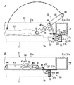
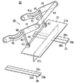
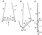
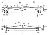
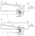
図1は本発明の第1の実施形態に係るパネル吊り具を用いてパネルを吊り上げる作業の状態を示す斜視図である。FIG. 1 is a perspective view showing a state of an operation of lifting a panel using the panel hanger according to the first embodiment of the present invention. 図2は図1のX−X線に沿って見た矢視図である。FIG. 2 is an arrow view taken along line XX in FIG. 図3は前記パネルの断面図である。FIG. 3 is a sectional view of the panel. 図4は前記パネル吊り具の平面図である。FIG. 4 is a plan view of the panel hanger. 図5Aは図4のY−Y線における断面図に相当する図であって、スライド機構による第1嵌合部のパネル溝部への嵌め込み移動が行われる前の状態を示す。図5Bは図4のY−Y線における断面図であって、スライド機構による第1嵌合部のパネル溝部への嵌め込み移動が行われた後の状態を示す。図5Cは図5BのE部分の拡大図である。5A is a view corresponding to a cross-sectional view taken along line YY of FIG. 4 and shows a state before the sliding movement of the first fitting portion into the panel groove portion. FIG. 5B is a cross-sectional view taken along line YY of FIG. 4 and shows a state after the sliding movement of the first fitting portion into the panel groove portion. FIG. 5C is an enlarged view of a portion E in FIG. 5B. 図6Aは図5Aのスライド機構付近の拡大図であり、図6Bは図5Bのスライド機構付近の拡大図である。6A is an enlarged view of the vicinity of the slide mechanism of FIG. 5A, and FIG. 6B is an enlarged view of the vicinity of the slide mechanism of FIG. 5B. 図7は図4のZ−Z線における拡大断面図である。7 is an enlarged cross-sectional view taken along the line ZZ in FIG. 図8は前記パネル吊り具の分解斜視図である。FIG. 8 is an exploded perspective view of the panel hanger. 図9は前記スライド機構の一部分解斜視図である。FIG. 9 is a partially exploded perspective view of the slide mechanism. 図10A〜Cは前記パネル吊り具を用いてパネルを立て起こし移動する作業の工程を示す工程図である。10A to 10C are process diagrams illustrating a process of raising and moving a panel using the panel lifting tool. 図11A、11Bは本発明の第2の実施形態に係るパネル吊り具に装備された落下防止機構の全体構成を示す正面図である。図11Aは、前記落下防止機構の嵌め込み操作前の状態を示す。図11Bは、前記落下防止機構の嵌め込み操作後の状態を示す。11A and 11B are front views showing the overall configuration of the fall prevention mechanism equipped in the panel hanger according to the second embodiment of the present invention. FIG. 11A shows a state before the fitting operation of the fall prevention mechanism. FIG. 11B shows a state after the fitting operation of the fall prevention mechanism. 図12Aは図11Aの第2回動部材付近の拡大図であり、図12Bは図11Bの第2回動部材付近の拡大図である。12A is an enlarged view of the vicinity of the second rotating member of FIG. 11A, and FIG. 12B is an enlarged view of the vicinity of the second rotating member of FIG. 11B. 図13Aは本発明の第3の実施形態に係るパネル吊り具のうちの第1パネル吊り具の正面図であり、図13Bは前記パネル吊り具のうちの第2パネル吊り具の正面図である。FIG. 13A is a front view of a first panel hanger among the panel hanger according to the third embodiment of the present invention, and FIG. 13B is a front view of a second panel hanger of the panel hanger. . 図14A〜Dは前記第1パネル吊り具及び前記第2パネル吊り具を用いてパネルを反転させる作業の工程を示す工程図である。14A to 14D are process diagrams showing a process of reversing the panel using the first panel hanger and the second panel hanger. 図15A〜Eは同じく前記第1パネル吊り具及び前記第2パネル吊り具を用いてパネルを反転させる作業の別の例を示す工程図である。FIGS. 15A to 15E are process diagrams showing another example of the work of inverting the panel using the first panel hanger and the second panel hanger. 図16は本発明の第4の実施形態に係るパネル吊り具の分解斜視図である。FIG. 16 is an exploded perspective view of a panel hanger according to the fourth embodiment of the present invention. 図17は前記パネル吊り具を用いてパネルを反転させる作業の立て起こし状態を示す斜視図である。FIG. 17 is a perspective view showing an upright state of an operation of inverting the panel using the panel hanger.

以下、本発明を実施するための形態である実施形態を図面に基づいて説明する。   DESCRIPTION OF THE PREFERRED EMBODIMENTS Hereinafter, embodiments that are modes for carrying out the present invention will be described with reference to the drawings.

図1及び図2は本発明の第1の実施形態に係るパネル吊り具を用いてパネルを吊り上げる作業の状態を示す。図1及び図2において、1はパレット2上に平置き状態で複数積み重ねられたパネル、3は複数のパネル1,1,…のうちの最も上に位置するパネル1を吊り上げるためのパネル吊り具であり、パネル吊り具3は、本発明の第1の実施形態に係るものである。なお、図1では、パネル1を吊り上げるときには、パネル吊り具3は2つ使用しているが、1つ又は3つ以上使用してもよい。   1 and 2 show the state of the operation of lifting the panel using the panel hanger according to the first embodiment of the present invention. 1 and 2, 1 is a panel stacked in a flat state on a pallet 2, and 3 is a panel lifting tool for lifting the panel 1 positioned at the top of the plurality of panels 1, 1,. The panel hanger 3 is according to the first embodiment of the present invention. In FIG. 1, when the panel 1 is lifted, two panel suspensions 3 are used, but one or three or more may be used.

また、4はパネル吊り具3と協働してパネル1を吊り上げる吊り上げ装置であって、吊り上げ装置4は、クレーンで吊り上げられるレッカー吊部5と、レッカー吊部5に連結ワイヤ6を介して支持された電動ホイスト7とを備える。パネル吊り具3の一端側は、レッカー吊部5に連結ワイヤ8を介して支持されており、パネル吊り具3の他端側は、電動ホイスト7に連結ワイヤ9を介して支持されている。電動ホイスト7は、連結ワイヤ9の送り出し及び巻き取りをする機能を有し、この機能により、パネル吊り具3を介してパネル1を、略水平な状態と略垂直な立て起こし状態とに変更できるようになっている。   In addition, 4 is a lifting device that lifts the panel 1 in cooperation with the panel lifting tool 3, and the lifting device 4 is supported by a tow lifter 5 that is lifted by a crane and a connecting wire 6 to the tow lifter 5. The electric hoist 7 is provided. One end side of the panel hanger 3 is supported on the tow rack hanging portion 5 via a connecting wire 8, and the other end side of the panel hanger 3 is supported on the electric hoist 7 via a connecting wire 9. The electric hoist 7 has a function of feeding and winding the connecting wire 9. With this function, the panel 1 can be changed between a substantially horizontal state and a substantially vertical standing state via the panel hanger 3. It is like that.

パネル1は、図3に示すように、第1金属板11と第2金属板12との間に芯材13を設けたいわゆるサンドイッチパネルである。2枚の金属板11,12は、それぞれ接着剤を介して芯材13に固着されている。   As shown in FIG. 3, the panel 1 is a so-called sandwich panel in which a core member 13 is provided between a first metal plate 11 and a second metal plate 12. The two metal plates 11 and 12 are each fixed to the core member 13 via an adhesive.

金属板11,12は、厚みが0.25〜1.6mm程度の薄板材である。金属板11,12は、Al、Fe、Cu、ステンレス鋼等の各種金属板、アルミニウム−亜鉛合金メッキ鋼板、カラー鋼板、ホーロー鋼板、フッ素樹脂塗装鋼板、クラッド鋼板、サンドイッチ鋼板等のうちの一種を、プレス成形、押出成形、ロール成形等によって成形したものである。   The metal plates 11 and 12 are thin plate materials having a thickness of about 0.25 to 1.6 mm. The metal plates 11 and 12 are made of various kinds of metal plates such as Al, Fe, Cu, and stainless steel, aluminum-zinc alloy plated steel plates, color steel plates, enamel steel plates, fluororesin-coated steel plates, clad steel plates, sandwich steel plates, etc. , Formed by press molding, extrusion molding, roll molding or the like.

芯材13は、ロックウールやグラスウール、セラミックファイバー等の無機繊維体、又はウレタンフォームやフェノールフォーム等の樹脂発泡体等の板体である。芯材13のうち、左右の端部に配置される端部芯材14は、硬質であり、かつ耐火性を有する石膏ボードや珪酸カルシウム等の無機質材料が好適に用いられる。なお、芯材13は、端部芯材14を含めて全体が同じ材質であってもよい。   The core material 13 is a plate body such as an inorganic fiber body such as rock wool, glass wool, or ceramic fiber, or a resin foam body such as urethane foam or phenol foam. Of the core material 13, the end core material 14 disposed at the left and right ends is hard, and an inorganic material such as gypsum board or calcium silicate having fire resistance is preferably used. The core material 13 may be the same material as a whole including the end core material 14.

パネル1は、上下に並べて胴縁等の下地材に取り付けられて、建物の外壁等の壁を構成する。パネル1は、第1金属板11が屋外側に位置し、第2金属板12が屋内側に位置するように、下地材に取り付けられる。このことから、第1金属板11は、パネル1の表面1cをなし、第2金属板12は、パネル1の裏面1dをなす。なお、パネル1は、矩形状の平板である(図1参照)。   The panels 1 are arranged vertically and attached to a base material such as a trunk edge to constitute a wall such as an outer wall of a building. The panel 1 is attached to the base material such that the first metal plate 11 is located on the outdoor side and the second metal plate 12 is located on the indoor side. Therefore, the first metal plate 11 forms the front surface 1c of the panel 1, and the second metal plate 12 forms the back surface 1d of the panel 1. The panel 1 is a rectangular flat plate (see FIG. 1).

パネル1は、その一端部(詳しくは短手方向の一端部)1aに凸部15を有し、他端部1bに溝部16を有する。上下に並ぶパネル1は、上側に位置するパネル1の凸部15と、下側に位置するパネル1の溝部16とが嵌合して接続される。   The panel 1 has a convex portion 15 at one end portion (specifically, one end portion in the short side direction) 1a and a groove portion 16 at the other end portion 1b. In the panels 1 arranged in the vertical direction, the convex portion 15 of the panel 1 positioned on the upper side and the groove portion 16 of the panel 1 positioned on the lower side are fitted and connected.

溝部16は、第1壁部17と第2壁部18とによって構成されている。第1壁部17は、第1金属板11の他端部を中空に折り返して形成され、第2壁部18は、第2金属板12の他端部を中空に折り返して形成されている。   The groove portion 16 is constituted by a first wall portion 17 and a second wall portion 18. The first wall portion 17 is formed by folding the other end portion of the first metal plate 11 into a hollow shape, and the second wall portion 18 is formed by folding the other end portion of the second metal plate 12 into a hollow shape.

パネル1は、その一端部1aのうち凸部15の外側に、折り返しスカート部19と折り返し部20とを有する。折り返しスカート部19は、凸部15よりもパネル表面側に凸部15から離れて位置し、折り返し部20は、凸部15よりもパネル裏面側に凸部15から離れて位置する。   The panel 1 has a folded skirt portion 19 and a folded portion 20 outside the convex portion 15 in the one end portion 1a. The folded skirt portion 19 is located farther from the convex portion 15 on the panel surface side than the convex portion 15, and the folded portion 20 is located farther from the convex portion 15 on the panel back side than the convex portion 15.

また、パネル1は、パネル表面のうち第1壁部17の短手方向の一端側に、凹段部21を有する。パネル1は、凹段部21にねじ等の固定具が打ち込まれることによって、他端部1bが下地材に固定される。パネル1が上下に並べて下地材に取り付けられたとき、下側に位置するパネル1の凹段部21は、上側に位置するパネル1の折り返しスカート部19により表面側から覆われる。   Moreover, the panel 1 has the recessed step part 21 in the one end side of the transversal direction of the 1st wall part 17 among the panel surfaces. In the panel 1, the other end 1 b is fixed to the base material by driving a fixing tool such as a screw into the recessed step portion 21. When the panel 1 is vertically arranged and attached to the base material, the concave step portion 21 of the panel 1 positioned on the lower side is covered from the surface side by the folded skirt portion 19 of the panel 1 positioned on the upper side.

パネル吊り具3は、図4ないし図8に示すように、強度部材31と、第1嵌合部材32と、第2嵌合部材33と、連結部材34と、スライド機構35とを備えている。   As shown in FIGS. 4 to 8, the panel hanger 3 includes a strength member 31, a first fitting member 32, a second fitting member 33, a connecting member 34, and a slide mechanism 35. .

強度部材31は、パネル1の一端部1aから他端部1bに亘って、パネル1の上面上に配置される。強度部材31は、パネル1の一端部1aから他端部1bに亘って延びる一対の長辺部31a,31aと、一対の短辺部31b,31cとで矩形枠状に組み立てて構成されている。一対の短辺部31b,31cの長手方向の長さは、一対の長辺部31a,31aの長手方向の長さよりも短い。長辺部31a,31a及び短辺部31b,31cは、それぞれ四角筒状である。各長辺部31aの長手方向の両端はそれぞれ閉塞されている。強度部材31の材質は、ステンレス鋼等の金属、合金又は繊維強化樹脂等である。なお、パネル吊り具3の強度部材31以外の構成部材は、いずれも金属製又は合金製などである。   The strength member 31 is disposed on the upper surface of the panel 1 from the one end 1 a to the other end 1 b of the panel 1. The strength member 31 is constructed by assembling a rectangular frame with a pair of long side portions 31a and 31a extending from one end 1a to the other end 1b of the panel 1 and a pair of short side portions 31b and 31c. . The length in the longitudinal direction of the pair of short sides 31b, 31c is shorter than the length in the longitudinal direction of the pair of long sides 31a, 31a. The long side portions 31a and 31a and the short side portions 31b and 31c each have a rectangular tube shape. Both ends in the longitudinal direction of each long side portion 31a are closed. The material of the strength member 31 is a metal such as stainless steel, an alloy, or a fiber reinforced resin. The constituent members other than the strength member 31 of the panel hanger 3 are all made of metal or alloy.

強度部材31の一端部31dは、一方の短辺部31b及びこの短辺部31bを挟む一対の長辺部31a,31aの端部により構成される。強度部材31の他端部31eは、他方の短辺部31c及びこの短辺部31cを挟む一対の長辺部31a,31aの端部により構成される。   One end 31d of the strength member 31 is composed of one short side 31b and ends of a pair of long sides 31a and 31a sandwiching the short side 31b. The other end portion 31e of the strength member 31 is composed of the other short side portion 31c and the ends of a pair of long side portions 31a and 31a sandwiching the short side portion 31c.

第1嵌合部材32は、特に図5Cに示すように、強度部材31の一端部31dの下面に支え材36及びボルト30等を介して固定されている。第1嵌合部材32は、パネル1の凸部15に嵌め込み可能な第1嵌合部32aを有しており、第1嵌合部32aは、強度部材31の一端部31dに位置している。第1嵌合部32aは、パネル1の凸部15と折り返しスカート部19との間に嵌まり込む第1片部32bと、パネル1の凸部15と折り返し部20との間に嵌まり込む第2片部32cとを有する。   As shown particularly in FIG. 5C, the first fitting member 32 is fixed to the lower surface of the one end portion 31d of the strength member 31 via a support member 36, a bolt 30, and the like. The first fitting member 32 has a first fitting portion 32 a that can be fitted into the convex portion 15 of the panel 1, and the first fitting portion 32 a is located at one end portion 31 d of the strength member 31. . The first fitting portion 32 a is fitted between the first piece 32 b that fits between the convex portion 15 of the panel 1 and the folded skirt portion 19, and the convex portion 15 of the panel 1 and the folded portion 20. A second piece 32c.

第2嵌合部材33は、特に図6A、6Bに示すように、強度部材31の他端部31eに設けられている。第2嵌合部材33は、パネル1の溝部16に嵌め込み可能な第2嵌合部33aと、第2嵌合部33aの上側に第2嵌合部33aから離れて位置する第1片部33bと、第2嵌合部33aの下側に第2嵌合部33aから離れて位置する第2片部33cとを有している。パネル1の溝部16に第2嵌合部33aが嵌め込まれたときには、第2嵌合部33aと第1片部33bとの間にパネル1の第1壁部17が嵌め込まれ、第2嵌合部33aと第2片部33cとの間にパネル1の第2壁部18が嵌め込まれるようになっている。第2嵌合部33aは、強度部材31の他端部31eに位置し、スライド機構35により強度部材31の下面に沿って移動してパネル1の溝部16に嵌め込まれるように設けられている。   The second fitting member 33 is provided at the other end 31e of the strength member 31 as shown in FIGS. 6A and 6B in particular. The second fitting member 33 includes a second fitting portion 33a that can be fitted into the groove portion 16 of the panel 1, and a first piece portion 33b that is located on the upper side of the second fitting portion 33a and away from the second fitting portion 33a. And a second piece portion 33c located away from the second fitting portion 33a on the lower side of the second fitting portion 33a. When the second fitting portion 33a is fitted in the groove portion 16 of the panel 1, the first wall portion 17 of the panel 1 is fitted between the second fitting portion 33a and the first piece portion 33b, and the second fitting is performed. The second wall portion 18 of the panel 1 is fitted between the portion 33a and the second piece portion 33c. The second fitting portion 33 a is located at the other end portion 31 e of the strength member 31, and is provided so as to move along the lower surface of the strength member 31 by the slide mechanism 35 and fit into the groove portion 16 of the panel 1.

連結部材34は、特に図4に示すように、強度部材31の一端部31dと他端部31eにそれぞれ2個ずつ設けられている。各連結部材34は、強度部材31の一対の長辺部31a,31aの長手方向の一端面と他端面からそれぞれ突出させて取り付けられている。連結部材34は、リング状に形成された連結部34aを有する。連結部34aに対して、吊り上げ装置4の連結ワイヤ8,9がフック部材等を用いて連結される。本実施形態の場合、強度部材31の一端部31d側の連結部材34は、連結ワイヤ9に連結され、強度部材31の他端部31e側の連結部材34は、連結ワイヤ8に連結される。   As shown in FIG. 4 in particular, two connecting members 34 are provided at one end 31d and the other end 31e of the strength member 31, respectively. Each connecting member 34 is attached so as to protrude from one end surface and the other end surface in the longitudinal direction of the pair of long side portions 31 a, 31 a of the strength member 31. The connecting member 34 has a connecting portion 34a formed in a ring shape. The connecting wires 8 and 9 of the lifting device 4 are connected to the connecting portion 34a using a hook member or the like. In the present embodiment, the connecting member 34 on the one end 31 d side of the strength member 31 is connected to the connecting wire 9, and the connecting member 34 on the other end 31 e side of the strength member 31 is connected to the connecting wire 8.

スライド機構35は、第2嵌合部材33ひいては第2嵌合部33aを保持する保持部材37と、保持部材37を、第2嵌合部33aがパネル1の溝部16に嵌まり込む第1位置(図6B参照)と、第2嵌合部33aがパネル1の溝部16から離れる第2位置(図6A参照)との間で移動させるための操作部38とを有している。   The slide mechanism 35 includes a holding member 37 that holds the second fitting member 33 and thus the second fitting portion 33a, and the holding member 37, and a first position where the second fitting portion 33a fits into the groove portion 16 of the panel 1. (Refer FIG. 6B) and the operation part 38 for moving the 2nd fitting part 33a to the 2nd position (refer FIG. 6A) which leaves | separates from the groove part 16 of the panel 1. As shown in FIG.

保持部材37は、一対のガイド部材39,39(図4、7等参照)によるガイドの下で強度部材31の他端部31eの下面に沿って強度部材31の長手方向に移動可能に設けられている。保持部材37は、図9にも示すように、強度部材31の一対の長辺部31a,31a間に亘って延びる矩形平板状の水平板部37aと、水平板部37aの下面から垂下する垂直板部37bとを有する。図6A、6Bに示すように、保持部材37の垂直板部37bの内面側(左側)には第2嵌合部材33がボルト40等により固定されている。垂直板部37bは、水平板部37aの短手方向中間部を長手方向に沿って長く延びているが、垂直板部37bの長手方向の長さは、水平板部37aの長手方向の長さよりも短くて、水平板部37aの長手方向両端部には垂直板部37bが存在しないようになっている。そして、水平板部37aの長手方向両端部が一対のガイド部材39,39によりガイドされる。   The holding member 37 is provided so as to be movable in the longitudinal direction of the strength member 31 along the lower surface of the other end portion 31e of the strength member 31 under a guide by a pair of guide members 39, 39 (see FIGS. 4 and 7, etc.). ing. As shown in FIG. 9, the holding member 37 includes a rectangular flat plate-like horizontal plate portion 37a extending between the pair of long side portions 31a and 31a of the strength member 31, and a vertical hanging from the lower surface of the horizontal plate portion 37a. And a plate portion 37b. As shown in FIGS. 6A and 6B, the second fitting member 33 is fixed to the inner surface side (left side) of the vertical plate portion 37b of the holding member 37 with bolts 40 or the like. The vertical plate portion 37b extends long in the short-side intermediate portion of the horizontal plate portion 37a along the longitudinal direction. The length of the vertical plate portion 37b in the longitudinal direction is longer than the length of the horizontal plate portion 37a in the longitudinal direction. The vertical plate portions 37b do not exist at both ends in the longitudinal direction of the horizontal plate portion 37a. Then, both ends in the longitudinal direction of the horizontal plate portion 37a are guided by the pair of guide members 39, 39.

各ガイド部材39は、図7に示すように、強度部材31の長辺部31aの下面に長辺部31aと平行に固定された固定部39aと、固定部39aの保持部材37側の端部に段差部39bを介して形成されたガイド部39cとを有する。各ガイド部材39は、ガイド部39cと強度部材31の長辺部31aの下面との隙間に保持部材37の水平板部37aの長手方向端部を嵌め込んだ状態でガイドする。なお、図7では、保持部材37の垂直板部37bに装着される第2嵌合部材33などは省略している。   As shown in FIG. 7, each guide member 39 includes a fixed portion 39a fixed to the lower surface of the long side portion 31a of the strength member 31 in parallel with the long side portion 31a, and an end portion of the fixed portion 39a on the holding member 37 side. And a guide part 39c formed through a step part 39b. Each guide member 39 guides in a state in which the end portion in the longitudinal direction of the horizontal plate portion 37 a of the holding member 37 is fitted in the gap between the guide portion 39 c and the lower surface of the long side portion 31 a of the strength member 31. In FIG. 7, the second fitting member 33 attached to the vertical plate portion 37b of the holding member 37 is omitted.

図9に示すように、操作部38は、本実施形態の場合、一対の第1リンク41,41と一対の第2リンク42,42とを有するリンク機構からなる。各第1リンク41の長さは、各第2リンク42の長さの2倍以上である。   As shown in FIG. 9, in the case of this embodiment, the operation part 38 consists of a link mechanism which has a pair of 1st links 41 and 41 and a pair of 2nd links 42 and 42. As shown in FIG. The length of each first link 41 is at least twice the length of each second link 42.

図6A、6Bに示すように、各第1リンク41の一端部は、強度部材31の各長辺部31aの内側面における、短辺部31cから所定距離隔てた位置でかつ強度部材31の下面側の位置に、支軸43回りに回動可能(所定の角度範囲内で正逆回転可能)に支持されている。図9に示すように、各第1リンク41の他端部同士は、連結棒44により連結されている。また、各第1リンク41は、その中間部と支軸43側の端部との間に円弧状に湾曲した湾曲部41aを有する形状に形成されており、湾曲部41aには湾曲部41aと同一曲率の円弧状のガイド孔45が設けられている。   As shown in FIGS. 6A and 6B, one end portion of each first link 41 is located at a predetermined distance from the short side portion 31 c on the inner surface of each long side portion 31 a of the strength member 31 and on the bottom surface of the strength member 31. It is supported at a position on the side so as to be rotatable about the support shaft 43 (forward and reverse rotation within a predetermined angle range). As shown in FIG. 9, the other ends of the first links 41 are connected by a connecting rod 44. Each first link 41 is formed in a shape having a curved portion 41a that is curved in an arc shape between an intermediate portion thereof and an end portion on the side of the support shaft 43. The curved portion 41a includes a curved portion 41a and a curved portion 41a. An arcuate guide hole 45 having the same curvature is provided.

各第2リンク42の一端部は、その一端部に設けた摺動子46を介してガイド孔45に沿って移動可能に連結されており、各第2リンク42の他端部は、保持部材37の水平板部37aの短手方向の一端部に設けた軸受け部47に支軸48を介して回動可能に支持されている。支軸48は、一対の軸受け部47,47間に亘って架設されている。   One end of each second link 42 is movably connected along a guide hole 45 via a slider 46 provided at one end thereof, and the other end of each second link 42 is a holding member. A horizontal plate portion 37 a is supported by a bearing portion 47 provided at one end portion in the short direction of the horizontal plate portion 37 a through a support shaft 48 so as to be rotatable. The support shaft 48 is extended between the pair of bearing portions 47 and 47.

しかして、図6Aに示すように第2嵌合部33aがパネル1の溝部16から離れた第2位置に位置する状態から、操作部38の連結棒44を用いて各第1リンク41を支軸43回りに図で反時計方向に回動操作すると、各第2リンク42は、その一端部が摺動子46を介して、対応する第1リンク41のガイド孔45内を支軸43側に移動しながら支軸48回りに倒伏する。これに伴い、保持部材37が強度部材31の他端部31eの下面に沿ってパネル1側に移動して、図6Bに示す第1位置で第2嵌合部33aがパネル1の溝部16に嵌まり込むようになっている。   6A, the first link 41 is supported by using the connecting rod 44 of the operation portion 38 from the state where the second fitting portion 33a is located at the second position away from the groove portion 16 of the panel 1. When the second link 42 is rotated around the shaft 43 in the counterclockwise direction in the drawing, one end of each second link 42 passes through the slider 46 in the guide hole 45 of the corresponding first link 41 to the support shaft 43 side. Lie down around the spindle 48 while moving. Accordingly, the holding member 37 moves to the panel 1 side along the lower surface of the other end portion 31e of the strength member 31, and the second fitting portion 33a becomes the groove portion 16 of the panel 1 at the first position shown in FIG. It comes to fit.

次に、パネル吊り具3を用いて、パレット2上に平置き状態で複数積み重ねられたパネル1,1,…のうちの最も上に位置するパネル1を立て起こし移動する作業の手順の一例について、図1、図2及び図10を参照しながら説明する。   Next, an example of a procedure for raising and moving the uppermost panel 1 among the panels 1, 1,... Stacked in a flat state on the pallet 2 using the panel lifting tool 3. This will be described with reference to FIGS. 1, 2, and 10. FIG.

先ず初めに、パネル吊り具3の4つの連結部材34,34,34,34に対し、吊り上げ装置4の所定の連結ワイヤ8,9を連結する。その際、パネル吊り具3の一端側の2つの連結部材34,34に対しては、電動ホイスト7からの連結ワイヤ9を連結し、パネル吊り具3の他端側の2つの連結部材34,34に対しては、レッカー吊部5からの連結ワイヤ8を連結する。   First, the predetermined connecting wires 8 and 9 of the lifting device 4 are connected to the four connecting members 34, 34, 34, 34 of the panel hanger 3. At that time, the connecting wire 9 from the electric hoist 7 is connected to the two connecting members 34, 34 on one end side of the panel hanger 3, and the two connecting members 34, 34 on the other end side of the panel hanger 3 are connected. For 34, the connecting wire 8 from the wrecker suspension 5 is connected.

続いて、吊り上げ装置4によりパネル吊り具3を水平状態で一旦吊り上げた後、パネル吊り具3の強度部材31を、パレット2上に積み重ねられた複数のパネル1,1,…のうちの最も上に位置するパネル1上に位置を合わせて載せる。次いで、強度部材31の一端部31dに位置する第1嵌合部32aをパネル1の凸部15に嵌め込むとともに、強度部材31の他端部31eに位置する第2嵌合部33aをパネル1の溝部16に嵌め込むことにより、強度部材31の下面に第1嵌合部32a及び第2嵌合部33aを介してパネル1を水平状態で保持する。   Subsequently, after lifting the panel suspension 3 in a horizontal state by the lifting device 4, the strength member 31 of the panel suspension 3 is the uppermost of the plurality of panels 1, 1,... Stacked on the pallet 2. The panel is placed on the panel 1 positioned at the position. Next, the first fitting portion 32 a located at one end 31 d of the strength member 31 is fitted into the convex portion 15 of the panel 1, and the second fitting portion 33 a located at the other end 31 e of the strength member 31 is fitted to the panel 1. The panel 1 is held in a horizontal state on the lower surface of the strength member 31 via the first fitting portion 32a and the second fitting portion 33a.

次いで、図2及び図10Aに示すように、吊り上げ装置4でパネル1を保持したパネル吊り具3を水平状態のまま所定寸法吊り上げる。   Next, as shown in FIGS. 2 and 10A, the lifting device 4 lifts the panel lifting tool 3 holding the panel 1 in a horizontal state with a predetermined dimension.

続いて、図1及び図10Bに示すように、電動ホイスト7から連結ワイヤ9を送り出すことにより、強度部材31の他端部31eの連結部材34を支点にして、強度部材31の一端部31dを回動させる。   Subsequently, as shown in FIG. 1 and FIG. 10B, by feeding the connecting wire 9 from the electric hoist 7, the connecting member 34 of the other end 31 e of the strength member 31 is used as a fulcrum and the one end 31 d of the strength member 31 is moved. Rotate.

次いで、図10Cに示すように、強度部材31の一端部31dを下側に、強度部材31の他端部31eを上側にしてパネル吊り具3を垂直に立て、パネル吊り具3に保持されたパネル1を立ち起こす。   Next, as shown in FIG. 10C, the panel hanger 3 is vertically erected with the one end 31 d of the strength member 31 on the lower side and the other end 31 e of the strength member 31 on the upper side, and is held by the panel hanger 3. Raise panel 1.

その後、吊り上げ装置4を水平移動させることにより、パネル1を立て起こし状態のまま移動させることができる。   Thereafter, by moving the lifting device 4 horizontally, the panel 1 can be moved upright.

このようなパネル吊り具3を用いてパネル1を立て起こし移動する作業では、パネル吊り具3の強度部材31の下面に第1嵌合部32a及び第2嵌合部33aを介してパネル1が吊り上げられる。このとき、両端部が支持された状態でパネル1を吊り上げることができるので、吊り上げ時のパネル1の姿勢が不安定にならず、パネル1を支持する入手が不要となって、人手がかかりにくくなる。   In the operation of raising and moving the panel 1 using such a panel hanger 3, the panel 1 is placed on the lower surface of the strength member 31 of the panel hanger 3 via the first fitting portion 32a and the second fitting portion 33a. Can be lifted. At this time, since the panel 1 can be lifted in a state where both ends are supported, the posture of the panel 1 at the time of lifting does not become unstable, and it is not necessary to obtain support for the panel 1, and it is difficult to take manpower. Become.

また、パネル1の積み替え作業では、従来の如く立て起こし、吊り上げ、移動及び倒伏を繰り返す必要はなく、単に吊り上げ、移動及び吊り下げを繰り返すだけで足りるため、作業の迅速化を図ることができる。   Further, in the transshipment work of the panel 1, it is not necessary to erection, lift, move, and lie down as in the prior art, and it is sufficient to simply lift, move, and suspend, so that the work can be speeded up.

特に、本実施形態の場合、第1嵌合部32aは、強度部材31の下面に固定されており、第2嵌合部33aは、スライド機構35により強度部材31の下面に沿って移動してパネル1の溝部16に嵌め込まれるように設けられている。このため、パネル1の上面上に強度部材31を配置するときに、強度部材31の下面に固定された第1嵌合部32aをパネル1の凸部15に嵌め込んだ後、スライド機構35により第2嵌合部33aを強度部材31の下面に沿ってパネル1側に移動させてパネル1の溝部16に嵌め込むことができる。この結果、嵌め込み操作を比較的簡単に行うことができ、その分作業の迅速化に寄与することができる。   In particular, in the case of the present embodiment, the first fitting portion 32a is fixed to the lower surface of the strength member 31, and the second fitting portion 33a is moved along the lower surface of the strength member 31 by the slide mechanism 35. It is provided so as to be fitted into the groove 16 of the panel 1. For this reason, when the strength member 31 is disposed on the upper surface of the panel 1, the first fitting portion 32 a fixed to the lower surface of the strength member 31 is fitted into the convex portion 15 of the panel 1, and then the slide mechanism 35 is used. The second fitting portion 33 a can be moved along the lower surface of the strength member 31 toward the panel 1 and can be fitted into the groove portion 16 of the panel 1. As a result, the fitting operation can be performed relatively easily, which can contribute to speeding up the work.

その上、スライド機構35は、強度部材31の下面に沿って移動可能に設けられた保持部材37を有し、保持部材37で第2嵌合部33aを保持する。また、スライド機構35は、保持部材37を、第2嵌合部33aがパネル1の溝部16に嵌まり込む第1位置と、第2嵌合部33aがパネル1の溝部16から離れる第2位置との間で移動させるための操作部38を有している。このため、操作部38による保持部材37の移動を円滑に行うことができ、操作の容易性及び動作の信頼性を高めることができる。特に、本実施形態のように、操作部38が第1リンク41と第2リンク42とを有するリンク機構からなるため、動作の信頼性をより高めることができる。   In addition, the slide mechanism 35 has a holding member 37 provided so as to be movable along the lower surface of the strength member 31, and holds the second fitting portion 33 a by the holding member 37. The slide mechanism 35 has the holding member 37 in a first position where the second fitting portion 33a fits into the groove portion 16 of the panel 1 and a second position where the second fitting portion 33a moves away from the groove portion 16 of the panel 1. And an operation unit 38 for moving between the two. For this reason, the holding member 37 can be smoothly moved by the operation unit 38, and the ease of operation and the reliability of the operation can be enhanced. In particular, as in the present embodiment, since the operation unit 38 includes a link mechanism having the first link 41 and the second link 42, the operation reliability can be further increased.

図11A、11Bは本発明の第2の実施形態に係るパネル吊り具60を示す。パネル吊り具60は、強度部材31の下面に第1嵌合部32a及び第2嵌合部33aを介して保持されたパネル1の落下を防止する落下防止機構61をさらに備えること以外は、第1の実施形態に係るパネル吊り具3と同じであり、同一の部材及び部位には同一符号を付してその説明は省略する。   11A and 11B show a panel hanger 60 according to a second embodiment of the present invention. The panel hanger 60 is provided with a drop prevention mechanism 61 for preventing the panel 1 held on the lower surface of the strength member 31 from being held via the first fitting portion 32a and the second fitting portion 33a. It is the same as the panel hanger 3 according to the first embodiment, and the same members and parts are denoted by the same reference numerals and description thereof is omitted.

落下防止機構61は、強度部材31の各長辺部31aの外側面に一対設けられるが、以下の説明では、強度部材31の手前側(正面側)の長辺部31aの外側面に設けられる落下防止機構61について説明する。落下防止機構61は、第1回動部材62と、第2回動部材63と、操作部材64とを有している。   A pair of drop prevention mechanisms 61 are provided on the outer side surface of each long side portion 31a of the strength member 31, but in the following description, they are provided on the outer side surface of the long side portion 31a on the near side (front side) of the strength member 31. The fall prevention mechanism 61 will be described. The fall prevention mechanism 61 includes a first rotation member 62, a second rotation member 63, and an operation member 64.

第1回動部材62は、強度部材31の一端部31dでかつ強度部材31の下面に近い位置に、支軸65回りに回動可能に支持されている。また、第1回動部材62は、第1嵌合部32aないし第1嵌合部材32が嵌め込まれた状態のパネル1の一端部1aに嵌め込み可能な凹部66を有している。   The first rotating member 62 is supported so as to be rotatable around the support shaft 65 at a position near one end 31 d of the strength member 31 and near the lower surface of the strength member 31. Moreover, the 1st rotation member 62 has the recessed part 66 which can be engage | inserted in the one end part 1a of the panel 1 in the state in which the 1st fitting part 32a thru | or the 1st fitting member 32 were engage | inserted.

第2回動部材63は、図12A、12Bに拡大詳示するように、強度部材31の他端部31eでかつ強度部材31の下面に近い位置に、支軸67回りに回動可能に支持されている。また、第2回動部材63は、第2嵌合部33aないし第2嵌合部材33が嵌め込まれた状態のパネル1の他端部1bに嵌め込み可能な凹部68を有している。   As shown in enlarged detail in FIGS. 12A and 12B, the second rotating member 63 is supported at the other end 31e of the strength member 31 and at a position close to the lower surface of the strength member 31 so as to be rotatable around the support shaft 67. Has been. Moreover, the 2nd rotation member 63 has the recessed part 68 which can be engage | inserted in the other end part 1b of the panel 1 in the state in which the 2nd fitting part 33a thru | or the 2nd fitting member 33 were fitted.

操作部材64は、所定の長さを有するI字形の平板状の部材であり、操作部材64の中心部は、強度部材31の長手方向中間部に、支軸69回りに回動可能に支持されている。操作部材64の一端は、連結棒71を介して第1回動部材62に連結されており、操作部材64の他端は、連結棒72を介して第2回動部材63に連結されている。そして、操作部材64を支軸69回りに回動操作すると、第1回動部材62及び第2回動部材63がそれぞれ支軸65,67回りに回動するようになっている。   The operation member 64 is an I-shaped flat plate member having a predetermined length, and the central portion of the operation member 64 is supported at the middle portion in the longitudinal direction of the strength member 31 so as to be rotatable around the support shaft 69. ing. One end of the operating member 64 is connected to the first rotating member 62 via the connecting rod 71, and the other end of the operating member 64 is connected to the second rotating member 63 via the connecting rod 72. . When the operation member 64 is rotated about the support shaft 69, the first rotation member 62 and the second rotation member 63 are rotated about the support shafts 65 and 67, respectively.

第1回動部材62は、その凹部66が第1嵌合部32a及びパネル1の一端部1aに嵌まり込む第1位置と、凹部66が第1嵌合部32a及びパネル1の一端部1aの上方に退避する第2位置との間で支軸65回りに回動する。また、第2回動部材63は、その凹部68が第2嵌合部33a及びパネル1の他端部1bに嵌まり込む第1位置(図12B参照)と、凹部68が第2嵌合部33a及びパネル1の他端部1bの上方に退避する第2位置(図12A参照)との間で支軸67回りに回動する。   The first rotation member 62 has a first position where the concave portion 66 fits into the first fitting portion 32 a and the one end portion 1 a of the panel 1, and the concave portion 66 includes the first fitting portion 32 a and the one end portion 1 a of the panel 1. It pivots around the support shaft 65 with respect to the second position retracted upward. The second rotating member 63 has a first position (see FIG. 12B) where the concave portion 68 fits into the second fitting portion 33a and the other end portion 1b of the panel 1, and the concave portion 68 is the second fitting portion. It rotates about the support shaft 67 between the second position (see FIG. 12A) retracted above 33a and the other end 1b of the panel 1.

第2の実施形態においては、第1の実施形態の場合と同様な作用効果を奏する以外に、パネル吊り具60が、強度部材31の下面に第1嵌合部32a及び第2嵌合部33aを介して保持されたパネル1の落下を防止する落下防止機構61をさらに備えることから、以下のような作用効果をも奏する。   In the second embodiment, the panel hanger 60 has a first fitting portion 32a and a second fitting portion 33a on the lower surface of the strength member 31 in addition to the same effects as those of the first embodiment. Furthermore, since the fall prevention mechanism 61 which prevents the fall of the panel 1 hold | maintained via is further provided, there also exist the following effects.

すなわち、パネル吊り具60を用いてパネル1を吊り上げるときには、落下防止機構61の操作部材64を操作して、第1回動部材62の凹部66が第1嵌合部32a及びパネル1の一端部1aに嵌まり込む状態にするとともに、第2回動部材63の凹部68が第2嵌合部33a及びパネル1の他端部1bに嵌まり込む状態にすることができる。このような状態では、パネル1の両端部1a,1bは、それぞれ第1嵌合部32a及び第2嵌合部33aを介して強度部材31に支持されるだけでなく、第1回動部材62及び第2回動部材63を介して強度部材31に支持されるため、吊り上げ状態からのパネル1の落下を防止することができる。   That is, when the panel 1 is lifted using the panel lifting tool 60, the operation member 64 of the fall prevention mechanism 61 is operated so that the concave portion 66 of the first rotating member 62 becomes the first fitting portion 32 a and one end portion of the panel 1. In addition to being fitted into 1a, the recess 68 of the second rotating member 63 can be fitted into the second fitting portion 33a and the other end 1b of the panel 1. In such a state, both end portions 1a and 1b of the panel 1 are not only supported by the strength member 31 via the first fitting portion 32a and the second fitting portion 33a, but also the first rotating member 62. And since it is supported by the strength member 31 via the second rotating member 63, it is possible to prevent the panel 1 from being dropped from the suspended state.

特に、本実施形態の場合、第1回動部材62及び第2回動部材63がそれぞれ第1位置に位置するとき、各回動部材62,63の重心は、それぞれその支点である支軸65,67よりも強度部材31の端部31d,31eの端側に位置するため、パネル吊り具60を用いてパネル1を水平な状態で持ち上げた場合でも各回動部材62,63はそれぞれ第1位置に留まるようになり、安全が確保される。   In particular, in the case of the present embodiment, when the first rotating member 62 and the second rotating member 63 are respectively positioned at the first position, the center of gravity of each rotating member 62, 63 is the supporting shaft 65, which is its fulcrum, respectively. 67, the rotating members 62 and 63 are in the first position even when the panel 1 is lifted in a horizontal state using the panel hanger 60, because it is located on the end side of the end portions 31d and 31e of the strength member 31. It will stay and safety will be ensured.

なお、連結部材61と各回動部材62,63とを連結する部材としては、第2の実施形態の如き連結棒71,72の代わりに、ワイヤ等を用いてもよい。また、連結部材61は、第2の実施形態の如き形状のものに限定されないのは言うまでもない。   As a member for connecting the connecting member 61 and the rotating members 62 and 63, a wire or the like may be used instead of the connecting rods 71 and 72 as in the second embodiment. Needless to say, the connecting member 61 is not limited to the shape as in the second embodiment.

図13A、13Bは本発明の第3の実施形態に係るパネル吊り具を示す。パネル吊り具は、パネル1の厚み方向の一方の面である表面1cに装着可能な第1パネル吊り具80(図13B参照)と、パネル1の厚み方向の他方の面である裏面1dに装着可能な第2パネル吊り具90(図13A参照)とを含む。   13A and 13B show a panel hanger according to a third embodiment of the present invention. The panel hanger is attached to the first panel hanger 80 (see FIG. 13B) that can be attached to the front surface 1c, which is one surface in the thickness direction of the panel 1, and the back surface 1d, which is the other surface in the thickness direction of the panel 1. Possible second panel hanger 90 (see FIG. 13A).

第1パネル吊り具80及び第2パネル吊り具90は、いずれもその構成部材のうちの第1嵌合部材81,91及び第2嵌合部材82,92の構成が異なるだけであり、その他の構成は、第1の実施形態に係るパネル吊り具3の場合と同じであり、同一の部材及び部位には同一符号を付してその説明は省略する。   The first panel hanger 80 and the second panel hanger 90 are different only in the configuration of the first fitting members 81 and 91 and the second fitting members 82 and 92 among the components. The configuration is the same as in the case of the panel hanger 3 according to the first embodiment, and the same members and parts are denoted by the same reference numerals and description thereof is omitted.

第1パネル吊り具80の第1嵌合部材81は、強度部材31の一端部31dの下面に支え材83及びボルト84等を介して固定されている。また、第1嵌合部材81は、第1の実施形態に係るパネル吊り具3の第1嵌合部材32の場合と同じく、パネル1の凸部15に嵌め込み可能な第1嵌合部81aを有しており、第1嵌合部81aは、強度部材31の一端部31dに位置している。第1嵌合部81aは、パネル1の凸部15と折り返しスカート部19との間に嵌まり込む第1片部81bと、パネル1の凸部15と折り返し部20との間に嵌まり込む第2片部81cとを有する。   The first fitting member 81 of the first panel hanger 80 is fixed to the lower surface of the one end 31d of the strength member 31 via a support member 83, a bolt 84, and the like. Moreover, the 1st fitting member 81 has the 1st fitting part 81a which can be fitted in the convex part 15 of the panel 1 similarly to the case of the 1st fitting member 32 of the panel hanger 3 which concerns on 1st Embodiment. The first fitting portion 81 a is located at one end portion 31 d of the strength member 31. The first fitting portion 81a fits between the first piece portion 81b fitted between the convex portion 15 of the panel 1 and the folded skirt portion 19, and between the convex portion 15 of the panel 1 and the folded portion 20. A second piece 81c.

第1パネル吊り具80の第2嵌合部材82は、スライド機構により強度部材31の他端部31eの下面に沿って移動してパネル1の溝部16に嵌め込まれるように設けられている。スライド機構の構成は、図示していないが、第1の実施形態に係るパネル吊り具3のスライド機構35の構成と同じある。第2嵌合部材82は、スライド機構の保持部材85にボルト86で固定して保持されている。また、第2嵌合部材82は、第1の実施形態に係るパネル吊り具3の第2嵌合部材33の場合と同じく、パネル1の溝部16に嵌め込み可能な第2嵌合部82aと、第2嵌合部82aの上側に第2嵌合部33aから離れて位置する第1片部82bと、第2嵌合部82aの下側に第2嵌合部82aから離れて位置する第2片部82cとを有している。そして、パネル1の溝部16に第2嵌合部82aが嵌め込まれたときには、第2嵌合部82aと第1片部82bとの間にパネル1の第1壁部17が嵌め込まれ、第2嵌合部82aと第2片部82cとの間にパネル1の第2壁部18が嵌め込まれるようになっている。第2嵌合部82aは、強度部材31の他端部31eに位置している。   The 2nd fitting member 82 of the 1st panel hanger 80 is provided so that it may move along the lower surface of the other end part 31e of the strength member 31 by a slide mechanism, and it may be fitted in the groove part 16 of the panel 1. FIG. Although the configuration of the slide mechanism is not shown, it is the same as the configuration of the slide mechanism 35 of the panel hanger 3 according to the first embodiment. The second fitting member 82 is held by being fixed to the holding member 85 of the slide mechanism with a bolt 86. Moreover, the 2nd fitting member 82 is the same as the case of the 2nd fitting member 33 of the panel hanger 3 which concerns on 1st Embodiment, The 2nd fitting part 82a which can be fitted in the groove part 16 of the panel 1, A first piece 82b located away from the second fitting portion 33a above the second fitting portion 82a, and a second located away from the second fitting portion 82a below the second fitting portion 82a. And one piece 82c. And when the 2nd fitting part 82a is inserted in the groove part 16 of the panel 1, the 1st wall part 17 of the panel 1 is inserted between the 2nd fitting part 82a and the 1st piece part 82b, and 2nd The second wall portion 18 of the panel 1 is fitted between the fitting portion 82a and the second piece portion 82c. The second fitting portion 82 a is located at the other end portion 31 e of the strength member 31.

一方、第2パネル吊り具90の第1嵌合部材91は、強度部材31の一端部31dの下面に支え材93及びボルト94等を介して固定されている。また、第1嵌合部材91は、第1パネル吊り具80の第1嵌合部材81の場合と同じく、パネル1の凸部15に嵌め込み可能な第1嵌合部91aを有しており、第1嵌合部91aは、強度部材31の一端部31dに位置している。第1嵌合部91aは、パネル1の凸部15と折り返しスカート部19との間に嵌まり込む第1片部91bと、パネル1の凸部15と折り返し部20との間に嵌まり込む第2片部91cとを有する。ただし、第1嵌合部材91の断面形状は、第1パネル吊り具80の第1嵌合部材81の断面形状と比べて、上下反対に、つまり断面形状の上下方向中心線を挟んで線対称になっている。   On the other hand, the first fitting member 91 of the second panel hanger 90 is fixed to the lower surface of the one end portion 31d of the strength member 31 via a support member 93, a bolt 94, and the like. Moreover, the 1st fitting member 91 has the 1st fitting part 91a which can be fitted in the convex part 15 of the panel 1 similarly to the case of the 1st fitting member 81 of the 1st panel hanger 80, The first fitting portion 91 a is located at one end portion 31 d of the strength member 31. The first fitting portion 91a is fitted between the first piece 91b fitted between the convex portion 15 of the panel 1 and the folded skirt portion 19, and between the convex portion 15 and the folded portion 20 of the panel 1. A second piece 91c. However, the cross-sectional shape of the first fitting member 91 is line-symmetric with respect to the cross-sectional shape of the first fitting member 81 of the first panel hanger 80 in the upside down direction, that is, across the vertical center line of the cross-sectional shape. It has become.

第2パネル吊り具90の第2嵌合部材92は、スライド機構により強度部材31の他端部31eの下面に沿って移動してパネル1の溝部16に嵌め込まれるように設けられている。スライド機構の構成は、図示していないが、第1の実施形態に係るパネル吊り具3のスライド機構35の構成と同じである。第2嵌合部材92は、スライド機構の保持部材95にボルト96で固定して保持されている。また、第2嵌合部材92は、パネル1の溝部16に嵌め込み可能な第2嵌合部92aと、第2嵌合部92aの下側に第2嵌合部33aから離れて位置する第1片部92bと、第2嵌合部92aの上側に第2嵌合部92aから離れて位置する第2片部92cとを有している。そして、パネル1の溝部16に第2嵌合部92aが嵌め込まれたときには、第2嵌合部92aと第1片部92bとの間にパネル1の第1壁部17が嵌め込まれ、第2嵌合部92aと第2片部92cとの間にパネル1の第2壁部18が嵌め込まれるようになっている。第2嵌合部92aは、強度部材31の他端部31eに位置している。第2嵌合部材92の断面形状は、第1パネル吊り具80の第2嵌合部材82の断面形状と比べて、上下反対に、つまり断面形状の上下方向中心線を挟んで線対称になっている。   The second fitting member 92 of the second panel hanger 90 is provided so as to move along the lower surface of the other end portion 31 e of the strength member 31 by the slide mechanism and to be fitted into the groove portion 16 of the panel 1. The configuration of the slide mechanism is not shown, but is the same as the configuration of the slide mechanism 35 of the panel hanger 3 according to the first embodiment. The second fitting member 92 is fixed and held by a bolt 96 to a holding member 95 of the slide mechanism. The second fitting member 92 includes a second fitting portion 92a that can be fitted into the groove portion 16 of the panel 1 and a first fitting portion that is located below the second fitting portion 92a and away from the second fitting portion 33a. It has the piece part 92b and the 2nd piece part 92c located away from the 2nd fitting part 92a above the 2nd fitting part 92a. When the second fitting portion 92a is fitted in the groove portion 16 of the panel 1, the first wall portion 17 of the panel 1 is fitted between the second fitting portion 92a and the first piece portion 92b. The second wall portion 18 of the panel 1 is fitted between the fitting portion 92a and the second piece portion 92c. The second fitting portion 92 a is located at the other end portion 31 e of the strength member 31. The cross-sectional shape of the second fitting member 92 is line-symmetrical with respect to the cross-sectional shape of the second fitting member 82 of the first panel hanger 80, upside down, that is, across the vertical center line of the cross-sectional shape. ing.

第3の実施形態においては、平置き状態のパネル1の表面1cが上向きのときには、第1パネル吊り具80を用いてパネル1の立て起こし移動する作業などを行うことができる。また、第3の実施形態においては、平置き状態のパネル1の裏面1dが上向きのときには、第2パネル吊り具90を用いてパネル1の立て起こし移動する作業などを行うことができる。第1パネル吊り具80又は第2パネル吊り具90を用いてパネル1の立て起こし移動する作業を行うときの作業手順は、第1の実施形態で説明した作業手順と同じである。   In the third embodiment, when the surface 1c of the flat panel 1 is facing upward, the panel 1 can be lifted and moved using the first panel hanger 80. In the third embodiment, when the rear surface 1d of the panel 1 in a flat state is facing upward, an operation of raising and moving the panel 1 using the second panel hanger 90 can be performed. The work procedure when performing the work of raising and moving the panel 1 using the first panel hanger 80 or the second panel hanger 90 is the same as the work procedure described in the first embodiment.

また、第3の実施形態においては、第1パネル吊り具80及び第2パネル吊り具90の両方を用いてパネル1を反転させる作業を行うことができる。   Moreover, in 3rd Embodiment, the operation | work which reverses the panel 1 using both the 1st panel hanger 80 and the 2nd panel hanger 90 can be performed.

次に、第1パネル吊り具80及び第2パネル吊り具90を用いて、平置き状態のパネル1を反転させる作業の一例の手順について、図14を参照しながら説明する。   Next, an example procedure for reversing the flat panel 1 using the first panel hanger 80 and the second panel hanger 90 will be described with reference to FIG.

先ず初めに、第1パネル吊り具80を、平置きされた、表面1cが上向き状態にあるパネル1に装着する。なお、パネル1への第1パネル吊り具80の装着は、強度部材31の一端部31dに位置する第1嵌合部81aをパネル1の凸部15に嵌め込むとともに、強度部材31の他端部31eに位置する第2嵌合部82aをパネル1の溝部16に嵌め込むことにより行われる。   First, the first panel hanger 80 is mounted on the panel 1 that is laid flat and has the surface 1c facing upward. The first panel hanger 80 is attached to the panel 1 by fitting the first fitting portion 81a located at one end 31d of the strength member 31 into the convex portion 15 of the panel 1 and the other end of the strength member 31. This is done by fitting the second fitting part 82a located in the part 31e into the groove part 16 of the panel 1.

続いて、第1パネル吊り具80の連結部材34に吊り上げ装置4を、上述したパネル1の立て起こし移動する作業の場合と同様に連結して、図14Aに示すように、パネル1を吊り上げ装置4によって水平状態のまま所定寸法吊り上げる。   Subsequently, the lifting device 4 is connected to the connecting member 34 of the first panel lifting tool 80 in the same manner as in the above-described operation of raising and moving the panel 1, and the panel 1 is lifted as shown in FIG. 14A. 4 is lifted to a predetermined dimension while being in a horizontal state.

次いで、図14Bに示すように、吊り上げ装置4の操作により、第1パネル吊り具80の強度部材31の他端部31eの連結部材34を支点にして、第1パネル吊り具80の強度部材31の一端部31dが他端部31eの鉛直下方に位置する状態にまで回動させる。   Next, as shown in FIG. 14B, by operating the lifting device 4, the strength member 31 of the first panel lifting device 80 with the connecting member 34 of the other end 31 e of the strength member 31 of the first panel lifting device 80 as a fulcrum. The one end portion 31d is rotated so as to be positioned vertically below the other end portion 31e.

続いて、図14Cに示すように、パレット2の端に第1パネル吊り具80の強度部材31の一端部31dの連結部材34などを接触させ、その接触箇所を支点にして、吊り上げ装置4の操作により、第1パネル吊り具80に装着されたパネル1が第1パネル吊り具80の上側に位置するように第1パネル吊り具80をパレット2上に倒伏させる。このとき、パネル1は、その裏面1dが上向き状態になる。   Subsequently, as shown in FIG. 14C, the end of the pallet 2 is brought into contact with the connecting member 34 of the one end portion 31d of the strength member 31 of the first panel hanger 80, and the contact portion is used as a fulcrum. By the operation, the first panel hanger 80 is laid down on the pallet 2 so that the panel 1 attached to the first panel hanger 80 is positioned above the first panel hanger 80. At this time, the back surface 1d of the panel 1 is in an upward state.

次いで、第1パネル吊り具80を、吊り上げ装置4及びパネル1から取り外す。続いて、第2パネル吊り具90を、パネル1にその上から装着する。この際、第1パネル吊り具80の強度部材31と第2パネル吊り具90の強度部材31とが、パネル1の長手方向に離れて位置するように、第2パネル吊り具90をパネル1に装着する。   Next, the first panel hanger 80 is detached from the lifting device 4 and the panel 1. Subsequently, the second panel hanger 90 is attached to the panel 1 from above. At this time, the second panel hanger 90 is attached to the panel 1 so that the strength member 31 of the first panel hanger 80 and the strength member 31 of the second panel hanger 90 are located apart from each other in the longitudinal direction of the panel 1. Installing.

続いて、図14Dに示すように、第2パネル吊り具90の連結部材34に吊り上げ装置4を連結して、パネル1を吊り上げ装置4によって吊り上げる。   Subsequently, as shown in FIG. 14D, the lifting device 4 is connected to the connecting member 34 of the second panel lifting tool 90, and the panel 1 is lifted by the lifting device 4.

以上によって、平置きされたパネル1の反転作業が終了する。   Thus, the reversing operation of the flat panel 1 is completed.

次に、同じく第1パネル吊り具80及び第2パネル吊り具90を用いて、平置き状態のパネル1を反転させる作業の手順の別の例について、図15を参照しながら説明する。   Next, another example of the procedure of inverting the panel 1 in a flat state using the first panel hanger 80 and the second panel hanger 90 will be described with reference to FIG.

先ず初めに、図15A〜Cに示すように、第1パネル吊り具80を、平置きされた、表面1cが上向き状態にあるパネル1に装着し、第1パネル吊り具80の連結部材34に吊り上げ装置4を連結して、パネル1を吊り上げ装置4によって水平状態のまま所定寸法吊り上げる。次いで、吊り上げ装置4の操作により、第1パネル吊り具80の強度部材31の他端部31eの連結部材34を支点にして、第1パネル吊り具80の強度部材31の一端部31dが他端部31eの鉛直下方に位置する状態にまで回動させる。これまでの作業手順は、先に説明した反転作業の手順と同じである。   First, as shown in FIGS. 15A to 15C, the first panel hanger 80 is mounted on the panel 1 that is laid flat and the surface 1c is facing upward, and is attached to the connecting member 34 of the first panel hanger 80. The lifting device 4 is connected, and the panel 1 is lifted by the lifting device 4 in a horizontal state with a predetermined dimension. Next, by operating the lifting device 4, the one end 31 d of the strength member 31 of the first panel lifting device 80 is connected to the other end 31 e of the strength member 31 of the first panel lifting device 80 by using the connecting member 34 as a fulcrum. Rotate to a state positioned vertically below the portion 31e. The work procedure so far is the same as the reverse work procedure described above.

続いて、図15Dに示すように、吊り上げ装置4により第1パネル吊り具80を介して鉛直状態に吊り上げられたパネル1に、第2パネル吊り具90を装着する。この際、第1パネル吊り具80の強度部材31と第2パネル吊り具90の強度部材31とが、パネル1の長手方向に離れて位置するように、第1パネル吊り具90をパネル1に装着する。   Subsequently, as shown in FIG. 15D, the second panel hanger 90 is mounted on the panel 1 that is lifted in the vertical state by the lifting device 4 via the first panel hanger 80. At this time, the first panel hanger 90 is placed on the panel 1 so that the strength member 31 of the first panel hanger 80 and the strength member 31 of the second panel hanger 90 are located apart from each other in the longitudinal direction of the panel 1. Installing.

次いで、第1パネル吊り具80の連結部材34と第2パネル吊り具90の連結部材34とを結合金具等で結合するなどした上で、吊り上げ装置4を、第1パネル吊り具80の連結部材34から第2パネル吊り具90の連結部材34に付け替える。続いて、第1パネル吊り具80を、パネル1から取り外す。   Next, after connecting the connecting member 34 of the first panel hanger 80 and the connecting member 34 of the second panel hanger 90 with a coupling bracket or the like, the lifting device 4 is connected to the connecting member of the first panel hanger 80. The connection member 34 of the second panel hanger 90 is replaced from 34. Subsequently, the first panel hanger 80 is removed from the panel 1.

次いで、図15Fに示すように、吊り上げ装置4によって、第2パネル吊り具90及びパネル1を、第2パネル吊り具90の強度部材31がパネル1の上方で水平に位置する姿勢まで反転させる。   Next, as shown in FIG. 15F, the lifting device 4 causes the second panel hanger 90 and the panel 1 to be reversed to the posture in which the strength member 31 of the second panel hanger 90 is positioned horizontally above the panel 1.

以上によって、平置きされたパネル1の反転作業が終了する。   Thus, the reversing operation of the flat panel 1 is completed.

本実施形態のパネル吊り具では、以上のような作業手順によって、パネル1を反転させることができるので、パネル1の現場加工などの利便性を高めることができる。   In the panel hanger according to the present embodiment, the panel 1 can be reversed by the above-described work procedure, and therefore, convenience such as on-site processing of the panel 1 can be enhanced.

図16及び図17は本発明の第4の実施形態に係るパネル吊り具100を示す。パネル吊り具100は、平置きされたパネル1を吊り上げるための器具であって、強度部材101と、第1嵌合部材102と、第1保持部材103と、第2嵌合部材104と、第2保持部材105と、連結部材106とを備えている。なお、パネル1の構成は、第1の実施形態の説明で図3を用いて説明した構成と同じであり、同一部位には同一符号を付してその説明は省略する。   16 and 17 show a panel hanger 100 according to a fourth embodiment of the present invention. The panel suspension 100 is an instrument for lifting the flat panel 1 and includes a strength member 101, a first fitting member 102, a first holding member 103, a second fitting member 104, and a first fitting member. 2 holding member 105 and connecting member 106 are provided. The configuration of the panel 1 is the same as the configuration described with reference to FIG. 3 in the description of the first embodiment, and the same portions are denoted by the same reference numerals and the description thereof is omitted.

強度部材101は、第1の実施形態に係るパネル吊り具3の強度部材31と同じく、パネル1の一端部1aから他端部1bに亘って、平置きされたパネル1の上面上(厚み方向の一方の面上)に配置される。強度部材101は、パネル1の一端部1aから他端部1bに亘って延びる一対の長辺部101a,101aと、一対の短辺部101b,101cとで矩形枠状に組み立てて構成されている。一対の短辺部101b,101cの長手方向の長さは、一対の長辺部101a,101aの長手方向の長さよりも短い。長辺部101a,101a及び短辺部101b,101cは、それぞれ四角筒状である。強度部材101の材質は、ステンレス鋼等の金属、合金又は繊維強化樹脂等である。なお、パネル吊り具100の強度部材101以外の構成部材は、いずれも金属製又は合金製などである。   Similar to the strength member 31 of the panel hanger 3 according to the first embodiment, the strength member 101 is placed on the upper surface of the panel 1 placed in a flat manner from one end 1a to the other end 1b of the panel 1 (in the thickness direction). On one side). The strength member 101 is configured by assembling a rectangular frame with a pair of long sides 101a and 101a extending from one end 1a to the other end 1b of the panel 1 and a pair of short sides 101b and 101c. . The length in the longitudinal direction of the pair of short sides 101b and 101c is shorter than the length in the longitudinal direction of the pair of long sides 101a and 101a. The long side portions 101a and 101a and the short side portions 101b and 101c each have a rectangular tube shape. The material of the strength member 101 is a metal such as stainless steel, an alloy, a fiber reinforced resin, or the like. The constituent members other than the strength member 101 of the panel hanger 100 are all made of metal or alloy.

強度部材101の一端部101dは、一方の短辺部101b及びこの短辺部101bを挟む一対の長辺部101a,101aの端部により構成される。強度部材101の他端部101eは、他方の短辺部101c及びこの短辺部101cを挟む一対の長辺部101a,101aの端部により構成される。   One end portion 101d of the strength member 101 is composed of one short side portion 101b and ends of a pair of long side portions 101a and 101a sandwiching the short side portion 101b. The other end 101e of the strength member 101 is composed of the other short side 101c and the ends of a pair of long sides 101a and 101a sandwiching the short side 101c.

第1嵌合部材102は、第1保持部材103にねじ等により固定されている。第1嵌合部材102は、パネル1の凸部15に嵌め込み可能な第1嵌合部102aを有している。第1嵌合部102aは、パネル1の凸部15と折り返しスカート部19との間に嵌まり込む第1片部102bと、パネル1の凸部15と折り返し部20との間に嵌まり込む第2片部102cとを有する。   The first fitting member 102 is fixed to the first holding member 103 with a screw or the like. The first fitting member 102 has a first fitting portion 102 a that can be fitted into the convex portion 15 of the panel 1. The first fitting portion 102a fits between the first piece portion 102b that fits between the convex portion 15 of the panel 1 and the folded skirt portion 19, and the convex portion 15 and the folded portion 20 of the panel 1. A second piece 102c.

第1保持部材103は、強度部材101の一端部101dに沿って延びる四角筒状の部材である。第1保持部材103の内側面(第2保持部材105と対向する側の側面)には第1嵌合部材102が固定されており、第1保持部材103は、第1嵌合部材102及びその第1嵌合部102aを保持している。   The first holding member 103 is a quadrangular cylindrical member that extends along one end 101 d of the strength member 101. The first fitting member 102 is fixed to the inner side surface of the first holding member 103 (the side surface facing the second holding member 105). The first holding member 103 includes the first fitting member 102 and the first fitting member 102. The first fitting portion 102a is held.

第1保持部材103の両端部にはそれぞれ、強度部材101と対向する側面にねじ孔107が設けられている。一方、強度部材101の一端部101dには、ねじ孔107に対応して、ねじ108が貫通可能な貫通孔109が一対設けられている。そして、一対のねじ108,108をそれぞれ、対応する貫通孔109を通してねじ孔107にねじ込むことにより、第1保持部材103が強度部材101の一端部101dに着脱自在に固定される。   At both ends of the first holding member 103, screw holes 107 are provided on the side surfaces facing the strength member 101. On the other hand, a pair of through holes 109 through which the screws 108 can pass are provided in one end 101 d of the strength member 101 corresponding to the screw holes 107. Then, the first holding member 103 is detachably fixed to the one end 101 d of the strength member 101 by screwing the pair of screws 108 and 108 into the screw holes 107 through the corresponding through holes 109.

第2嵌合部材104は、第2保持部材105にねじ等により固定されている。第2嵌合部材104は、パネル1の溝部16に嵌め込み可能な第2嵌合部104aと、第2嵌合部104aを挟む両側に位置する第1片部104b及び第2片部104cとを有している。   The second fitting member 104 is fixed to the second holding member 105 with screws or the like. The second fitting member 104 includes a second fitting portion 104a that can be fitted into the groove 16 of the panel 1, and a first piece 104b and a second piece 104c that are located on both sides of the second fitting portion 104a. Have.

第2保持部材105は、強度部材101の他端部101eに沿って延びる四角柱状の部材である。第2保持部材105の内側面(第1保持部材103と対向する側の側面)には第2嵌合部材104が固定されており、第2保持部材105は、第2嵌合部材104及びその第2嵌合部104aを保持している。   The second holding member 105 is a quadrangular columnar member that extends along the other end 101 e of the strength member 101. A second fitting member 104 is fixed to the inner side surface of the second holding member 105 (the side surface facing the first holding member 103). The second holding member 105 includes the second fitting member 104 and its second fitting member 104. The second fitting portion 104a is held.

第2保持部材105の両端部にはそれぞれ、強度部材101と対向する側面にねじ孔110が設けられている。一方、強度部材101の他端部101eには、ねじ孔110に対応して、ねじ111が貫通可能な貫通孔112が一対設けられている。そして、一対のねじ111,111をそれぞれ、対応する貫通孔112を通してねじ孔110にねじ込むことにより、第2保持部材105が強度部材101の他端部101eに着脱自在に固定される。   A screw hole 110 is provided on each side of the second holding member 105 on the side surface facing the strength member 101. On the other hand, the other end portion 101 e of the strength member 101 is provided with a pair of through holes 112 through which the screws 111 can pass, corresponding to the screw holes 110. Then, the second holding member 105 is detachably fixed to the other end portion 101e of the strength member 101 by screwing the pair of screws 111, 111 into the screw holes 110 through the corresponding through holes 112, respectively.

連結部材106は、第1保持部材103の外側面(第1嵌合部材102の固定面と反対側の側面)及び第2保持部材105の外側面(第2嵌合部材104の固定面と反対側の側面)にそれぞれ2個ずつ設けられている。連結部材106は、リング状に形成された連結部106aを有する。連結部106aに対して、吊り上げ装置4の連結ワイヤ8,9(図1参照)がフック部材等を用いて連結される。本実施形態の場合、第1保持部材103の連結部材106は、連結ワイヤ9に連結され、第2保持部材105の連結部材106は、連結ワイヤ8に連結される。   The connecting member 106 includes an outer surface of the first holding member 103 (side surface opposite to the fixing surface of the first fitting member 102) and an outer surface of the second holding member 105 (opposite to the fixing surface of the second fitting member 104). Two are provided on each side surface. The connecting member 106 has a connecting portion 106a formed in a ring shape. The connecting wires 8 and 9 (see FIG. 1) of the lifting device 4 are connected to the connecting portion 106a using a hook member or the like. In the present embodiment, the connecting member 106 of the first holding member 103 is connected to the connecting wire 9, and the connecting member 106 of the second holding member 105 is connected to the connecting wire 8.

パネル吊り具100は、強度部材101と異なる他の強度部材113をさらに備える。なお、2つの強度部材101,113を区別するために、以下の説明では、強度部材101を第1強度部材といい、強度部材113を第2強度部材という。   The panel hanger 100 further includes another strength member 113 different from the strength member 101. In order to distinguish the two strength members 101 and 113, in the following description, the strength member 101 is referred to as a first strength member, and the strength member 113 is referred to as a second strength member.

第2強度部材113は、パネル1の一端部1aから他端部1bに亘って、第1強度部材101とは反対に、パネル1の厚み方向の他方の面上に配置される。また、第2強度部材113は、第1強度部材101と同じく、パネル1の一端部1aから他端部1bに亘って延びる一対の長辺部113a,113aと、一対の短辺部113b,113cとで矩形枠状に組み立てて構成されている。一対の短辺部113b,113cの長手方向の長さは、一対の長辺部113a,113aの長手方向の長さよりも短い。長辺部113a,113a及び短辺部113b,113cは、それぞれ四角筒状である。第2強度部材113の材質は、ステンレス鋼等の金属、合金又は繊維強化樹脂等である。   The second strength member 113 is disposed on the other surface in the thickness direction of the panel 1 from the one end 1 a to the other end 1 b of the panel 1, opposite to the first strength member 101. Similarly to the first strength member 101, the second strength member 113 includes a pair of long side portions 113a and 113a extending from one end 1a to the other end 1b of the panel 1 and a pair of short sides 113b and 113c. And assembled into a rectangular frame shape. The length in the longitudinal direction of the pair of short sides 113b and 113c is shorter than the length in the longitudinal direction of the pair of long sides 113a and 113a. Each of the long side portions 113a and 113a and the short side portions 113b and 113c has a rectangular cylindrical shape. The material of the second strength member 113 is a metal such as stainless steel, an alloy, or a fiber reinforced resin.

第2強度部材113の一端部113dは、一方の短辺部113b及びこの短辺部113bを挟む一対の長辺部113a,113aの端部により構成される。第2強度部材113の他端部113eは、他方の短辺部113c及びこの短辺部113cを挟む一対の長辺部113a,113aの端部により構成される。   One end 113d of the second strength member 113 is composed of one short side 113b and ends of a pair of long sides 113a and 113a sandwiching the short side 113b. The other end 113e of the second strength member 113 is composed of the other short side 113c and the ends of a pair of long sides 113a and 113a sandwiching the short side 113c.

第2強度部材113の一端部113dには、ねじ114が貫通可能な貫通孔115が一対設けられている。一方、第1保持部材103の両端部には、それぞれ第2強度部材113と対向する側面にねじ孔116が設けられている。そして、一対のねじ114,114をそれぞれ、対応する貫通孔115を通してねじ孔116にねじ込むことにより、第1保持部材103が第2強度部材113の一端部113dに着脱自在に固定される。   One end 113 d of the second strength member 113 is provided with a pair of through holes 115 through which the screws 114 can pass. On the other hand, screw holes 116 are provided on both side portions of the first holding member 103 on the side surfaces facing the second strength member 113. Then, the first holding member 103 is detachably fixed to the one end 113 d of the second strength member 113 by screwing the pair of screws 114, 114 into the screw holes 116 through the corresponding through holes 115.

また、第2強度部材113の他端部113eには、ねじ117が貫通可能な貫通孔118が一対設けられている。一方、第2保持部材105の両端部には、それぞれ第2強度部材113と対向する側面にねじ孔119が設けられている。そして、一対のねじ117,117をそれぞれ、対応する貫通孔118を通してねじ孔119にねじ込むことにより、第2保持部材105が第2強度部材113の他端部113eに着脱自在に固定される。   Further, the other end 113e of the second strength member 113 is provided with a pair of through holes 118 through which the screws 117 can pass. On the other hand, screw holes 119 are provided on both sides of the second holding member 105 on the side surfaces facing the second strength member 113. Then, the second holding member 105 is detachably fixed to the other end 113e of the second strength member 113 by screwing the pair of screws 117 and 117 into the screw holes 119 through the corresponding through holes 118, respectively.

次に、パネル吊り具100を用いて、平置き状態のパネル1を立ち起こす作業の手順の一例について説明する。パネル吊り具100は、第1強度部材101に第1保持部材103のみが固定されたものを用いる。   Next, an example of a procedure for raising the panel 1 in a flat state using the panel hanger 100 will be described. As the panel hanger 100, a member in which only the first holding member 103 is fixed to the first strength member 101 is used.

先ず初めに、第1強度部材101を、平置きされた、裏面1dが表向き状態にあるパネル1の上面上に配置する。   First, the first strength member 101 is placed on the upper surface of the panel 1 that is laid flat and whose back surface 1d is in the face-up state.

続いて、パネル1の凸部15に、第1保持部材103に保持された第1嵌合部102aを嵌め込み、パネル1の溝部16に、第2保持部材105に保持された第2嵌合部104aを嵌め込んだ状態で、第2保持部材105を第1強度部材101に固定する。   Subsequently, the first fitting portion 102 a held by the first holding member 103 is fitted into the convex portion 15 of the panel 1, and the second fitting portion held by the second holding member 105 is inserted into the groove portion 16 of the panel 1. The second holding member 105 is fixed to the first strength member 101 with the 104a fitted.

次いで、第1保持部材103と第2保持部材105のそれぞれの連結部材106に吊り上げ装置4を連結して,パネル1を水平状態のまま所定寸法吊り上げる。   Next, the lifting device 4 is connected to the connecting members 106 of the first holding member 103 and the second holding member 105, and the panel 1 is lifted by a predetermined dimension while being in a horizontal state.

続いて、吊り上げ装置4の操作により、第2保持部材105の連結部材106を支点にして、第1強度部材101の一端部101dが他端部101eの鉛直下方に位置する状態にまで回動させる。   Subsequently, by operating the lifting device 4, the connecting member 106 of the second holding member 105 is used as a fulcrum and the one end portion 101 d of the first strength member 101 is rotated to a state positioned vertically below the other end portion 101 e. .

以上によって、パネル1の立て起こし作業が終了する。   Thus, the raising operation of the panel 1 is completed.

平置きされた、表面1cが上向き状態にあるパネル1に対しては、第2強度部材113に第1保持部材103のみが固定されたパネル吊り具100を用いることで、上述と同様の手順によってパネル1の立て起こし作業を行うことができる。   For the panel 1 that is laid flat and has the surface 1c facing upward, by using the panel hanger 100 in which only the first holding member 103 is fixed to the second strength member 113, the same procedure as described above is used. The panel 1 can be raised up.

また、パネル吊り具100は、第1強度部材101に第1保持部材103及び第2保持部材105が固定されたものを用いてパネル1の立て起こしを行った後、以下の手順を行うことでパネル1の反転作業を行うことができる。   Further, the panel hanger 100 performs the following procedure after raising the panel 1 using the first strength member 101 to which the first holding member 103 and the second holding member 105 are fixed. The panel 1 can be reversed.

すなわち、パネル1を立て起こした後、パネル1の第1強度部材101と反対側の面上(換言すればパネル1の厚み方向の他方の面上)に第2強度部材113を配置し、第2強度部材113に第1保持部材103及び第2保持部材105を固定する。   That is, after raising the panel 1, the second strength member 113 is disposed on the surface of the panel 1 opposite to the first strength member 101 (in other words, on the other surface in the thickness direction of the panel 1). The first holding member 103 and the second holding member 105 are fixed to the two-strength member 113.

次いで、第1保持部材103及び第2保持部材105から第1強度部材101を取り外す。その後、吊り上げ装置4によって、パネル1を、第2強度部材113がパネル1の上方に位置する姿勢まで反転させる。   Next, the first strength member 101 is removed from the first holding member 103 and the second holding member 105. Thereafter, the panel 1 is reversed by the lifting device 4 to the posture where the second strength member 113 is positioned above the panel 1.

以上によって反転作業が終了する。   This completes the reversing operation.

また、パネル吊り具100は、第2強度部材113に第1保持部材103及び第2保持部材105が固定されたものを用いてパネル1の立て起こしを行った後、上述と同様の手順を行うことでパネル1の反転作業を行うこともできる。   In addition, the panel hanger 100 performs the same procedure as described above after raising the panel 1 using a member in which the first holding member 103 and the second holding member 105 are fixed to the second strength member 113. Thus, the panel 1 can be reversed.

本実施形態の場合、パネル吊り具100を用いてパネル1を立ち起こす作業では、第1強度部材101又は第2強度部材113の下面に、第1嵌合部102a、第1保持部材103、第2嵌合部104a及び第2保持部材105を介してパネル1が吊り上げられる。このとき、両端部が支持された状態でパネル1を吊り上げることができるので、吊り上げ時のパネル1の姿勢が不安定にならず、パネル1を支持する人手が不要となって、人手がかかりにくくなる。   In the case of this embodiment, in the operation of raising the panel 1 using the panel hanger 100, the first fitting portion 102a, the first holding member 103, the first strength member 101 or the second strength member 113 are provided on the lower surface of the first strength member 101 or the second strength member 113. The panel 1 is lifted through the two fitting portions 104 a and the second holding member 105. At this time, since the panel 1 can be lifted in a state where both ends are supported, the posture of the panel 1 at the time of lifting does not become unstable, and a manpower for supporting the panel 1 becomes unnecessary, and it is difficult for the manpower to be taken. Become.

また、パネル吊り具100は、第1強度部材101の外に、第2強度部材113をさらに備えることで、パネル1を反転させることができるので、パネル1の現場加工などの利便性を高めることができる。   Moreover, since the panel hanger 100 can further invert the panel 1 by further including the second strength member 113 in addition to the first strength member 101, the convenience of on-site processing of the panel 1 is improved. Can do.

その上、パネル1の反転の際に、吊り上げ装置4の付け替えを必要としないので、パネル1の反転作業を容易に行うことができる。   In addition, since it is not necessary to replace the lifting device 4 when the panel 1 is reversed, the panel 1 can be easily reversed.

なお、本発明は前記第1〜第4の実施形態に限定されるものではなく、その種々の形態を包含するものである。例えば各実施形態では、レッカー吊部5と電動ホイスト7とを備える吊り上げ装置4を用いたが、この吊り上げ装置4は、これに限定されないのは勿論である。例えば、エアシリンダやダンパー等を用いて構成した吊り上げ装置、あるいは従来公知の吊り上げ装置を用いてもよい。   In addition, this invention is not limited to the said 1st-4th embodiment, The various form is included. For example, in each embodiment, the lifting device 4 provided with the tow suspension part 5 and the electric hoist 7 is used, but the lifting device 4 is not limited to this. For example, a lifting device configured using an air cylinder, a damper, or the like, or a conventionally known lifting device may be used.

また、前記第1〜第3の実施形態のパネル吊り具3,60,80,90は、第1嵌合部32a,81a,91aを有する第1嵌合部材32,81,91が、支え材36,83,93と一体に成形されたものであってもよい。また、前記第1〜第3の実施形態のパネル吊り具3,60,80,90は、第2嵌合部33a,82a,92aを有する第2嵌合部材33,82,92が、保持部材37,85,95と一体に成形されたものであってもよい。   Moreover, the panel hanger 3,60,80,90 of the said 1st-3rd embodiment has the 1st fitting member 32,81,91 which has 1st fitting part 32a, 81a, 91a, and a support material. It may be formed integrally with 36, 83, 93. In addition, the panel hanger 3, 60, 80, 90 of the first to third embodiments has a second fitting member 33, 82, 92 having a second fitting portion 33a, 82a, 92a, and a holding member. 37, 85, and 95 may be integrally formed.

さらに、第1の実施形態では、第2嵌合部33aを強度部材31の下面に固定し、第1嵌合部32aを、スライド機構35により強度部材31の下面に沿って移動してパネル1の凸部15に嵌め込まれるように設けてもよい。また、スライド機構35としては、第1の実施形態のようなリンク機構に限らないのは言うまでもない。   Furthermore, in 1st Embodiment, the 2nd fitting part 33a is fixed to the lower surface of the strength member 31, and the 1st fitting part 32a is moved along the lower surface of the strength member 31 by the slide mechanism 35, and the panel 1 is provided. It may be provided so as to be fitted into the convex portion 15. Needless to say, the slide mechanism 35 is not limited to the link mechanism as in the first embodiment.

加えて、強度部材31,101は、各実施形態のように矩形枠状のものに限らず、例えばパネル1の一端から他端に亘って延びる棒状のものでもよいのは言うまでもない。   In addition, it is needless to say that the strength members 31 and 101 are not limited to the rectangular frame shape as in each embodiment, but may be, for example, a rod shape extending from one end of the panel 1 to the other end.

以上説明したように、第1ないし第3の実施形態は、一端に凸部15を有し、他端に溝部16を有するパネル1を平置き状態から吊り上げるためのパネル吊り具3,60,80,90として、以下のような構成にしている。   As described above, in the first to third embodiments, the panel hanger 3, 60, 80 for lifting the panel 1 having the convex portion 15 at one end and the groove portion 16 at the other end from the flat position. , 90 are configured as follows.

すなわち、パネル吊り具3,60,80,90は、強度部材31と、第1嵌合部32a,81a,91aと、第2嵌合部33a,82a,92aと、連結部材34とを備える。強度部材31は、パネル1の一端から他端に亘って、パネル1の上面上に配置される。第1嵌合部32a,81a,91aは、強度部材31の一端部31dに位置し、凸部15に嵌め込み可能になっている。第2嵌合部33a,82a,92aは、強度部材31の他端部31eに位置し、溝部16に嵌め込み可能になっている。連結部材34は、強度部材31の一端部31dと他端部31eにそれぞれ設けられ、吊り上げ装置4に対して連結可能になっている。   That is, the panel hanger 3, 60, 80, 90 includes the strength member 31, the first fitting portions 32a, 81a, 91a, the second fitting portions 33a, 82a, 92a, and the connecting member 34. The strength member 31 is disposed on the upper surface of the panel 1 from one end of the panel 1 to the other end. The first fitting portions 32 a, 81 a, and 91 a are located at one end portion 31 d of the strength member 31 and can be fitted into the convex portion 15. The second fitting portions 33 a, 82 a, and 92 a are located at the other end portion 31 e of the strength member 31 and can be fitted into the groove portion 16. The connecting member 34 is provided at each of the one end 31 d and the other end 31 e of the strength member 31 and can be connected to the lifting device 4.

この構成では、強度部材31の下面に第1嵌合部32a,81a,91a及び第2嵌合部33a,82a,92aを介してパネル1が吊り上げられる。このとき、両端部が支持された状態でパネル1を吊り上げることができるので、吊り上げ時のパネル1の姿勢が不安定にならず,パネル1を支持する人手が不要となって、人手がかかりにくくなる。また、パネル1の積み替え作業では、従来の如く立て起こし、吊り上げ、移動及び倒伏を繰り返す必要はなく、単に吊り上げ、移動及び吊り下げを繰り返すだけで足りるため、作業の迅速化をより図ることができる。   In this configuration, the panel 1 is suspended from the lower surface of the strength member 31 via the first fitting portions 32a, 81a, 91a and the second fitting portions 33a, 82a, 92a. At this time, since the panel 1 can be lifted in a state where both ends are supported, the posture of the panel 1 at the time of lifting does not become unstable, and a manpower for supporting the panel 1 becomes unnecessary, and it is difficult to put a manpower on. Become. Further, in the transshipment work of the panel 1, it is not necessary to raise, move, and lie down as in the prior art, and it is sufficient to simply repeat the lifting, moving and hanging, so that the work can be speeded up. .

第1ないし第3の実施形態は、前述した構成に加えて、以下のような構成にしている。すなわち、第1嵌合部32a,81a,91a及び第2嵌合部33a,82a,92aのいずれか一方は、強度部材31の下面に固定されており、他方は、スライド機構35により強度部材31の下面に沿って移動して凸部15又は溝部16に嵌め込まれるように設けられている。   The first to third embodiments have the following configuration in addition to the configuration described above. That is, any one of the first fitting portions 32 a, 81 a, 91 a and the second fitting portions 33 a, 82 a, 92 a is fixed to the lower surface of the strength member 31, and the other is strength member 31 by the slide mechanism 35. It is provided so that it may move along the lower surface of the projection and be fitted into the convex portion 15 or the groove portion 16.

この構成では、パネル1の上面上に強度部材31を配置するとき、強度部材31の下面に固定された第1嵌合部32a,81a,91a又は第2嵌合部33a,82a,92aをパネル1の凸部15又は溝部16に嵌め込むとともに、スライド機構35により強度部材31の下面に沿って移動可能な第2嵌合部33a,82a,92a又は第1嵌合部32a,81a,91aをパネル1の溝部16側又は凸部15側に移動させてパネル1の溝部16又は凸部15に嵌め込む。この嵌め込み操作は、比較的簡単であるため、その分作業の迅速化に寄与することができる。   In this configuration, when the strength member 31 is disposed on the upper surface of the panel 1, the first fitting portions 32a, 81a, 91a or the second fitting portions 33a, 82a, 92a fixed to the lower surface of the strength member 31 are arranged on the panel. The second fitting portions 33a, 82a, and 92a or the first fitting portions 32a, 81a, and 91a that are fitted into the first convex portion 15 or the groove portion 16 and are movable along the lower surface of the strength member 31 by the slide mechanism 35 are provided. The panel 1 is moved to the groove 16 side or the convex part 15 side and fitted into the groove part 16 or convex part 15 of the panel 1. Since this fitting operation is relatively simple, it can contribute to speeding up the work.

第1ないし3の実施形態は、前述した構成に加えて、以下のような構成にしている。すなわち、スライド機構35は、強度部材31の下面に沿って移動可能に設けられた保持部材37を有し、保持部材37で他方(第1嵌合部32a又は第2嵌合部33a)を保持する。また、スライド機構35は、保持部材37を、他方が凸部15又は溝部16に嵌まり込む第1位置と、他方が凸部15又は溝部16から離れる第2位置との間で移動させるための操作部38を有している。このため、操作部38による保持部材37の移動を円滑に行うことができ、操作の容易性及び動作の信頼性を高めることができる。   The first to third embodiments have the following configuration in addition to the configuration described above. That is, the slide mechanism 35 includes a holding member 37 that is provided so as to be movable along the lower surface of the strength member 31, and holds the other (first fitting portion 32 a or second fitting portion 33 a) with the holding member 37. To do. Further, the slide mechanism 35 moves the holding member 37 between a first position where the other is fitted into the convex portion 15 or the groove portion 16 and a second position where the other is separated from the convex portion 15 or the groove portion 16. An operation unit 38 is provided. For this reason, the holding member 37 can be smoothly moved by the operation unit 38, and the ease of operation and the reliability of the operation can be enhanced.

第2の実施形態は、前述の構成に加えて、以下のような構成にしている。すなわち、パネル吊り具60は、強度部材31の下面に第1嵌合部32a及び第2嵌合部33aを介して保持されたパネル1の落下を防止する落下防止機構61をさらに備える。落下防止機構61は、第1回動部材62と、第2回動部材63と、操作部材64とを有している。第1回動部材62は、強度部材31の一端部31dに回動可能に支持され、第1嵌合部32aが嵌め込まれた状態のパネル1の一端部1aに嵌め込み可能な凹部66を有する。第2回動部材63は、強度部材31の他端部31eに回動可能に支持され、第2嵌合部33aが嵌め込まれた状態のパネル1の他端部1bに嵌め込み可能な凹部68を有する。操作部材64は、第1回動部材62及び第2回動部材63をそれぞれ回動操作するものである。   The second embodiment has the following configuration in addition to the configuration described above. That is, the panel hanger 60 further includes a fall prevention mechanism 61 that prevents the panel 1 held on the lower surface of the strength member 31 via the first fitting portion 32a and the second fitting portion 33a from dropping. The fall prevention mechanism 61 includes a first rotation member 62, a second rotation member 63, and an operation member 64. The 1st rotation member 62 is rotatably supported by the one end part 31d of the intensity | strength member 31, and has the recessed part 66 which can be engage | inserted in the one end part 1a of the panel 1 in the state in which the 1st fitting part 32a was engage | inserted. The second rotating member 63 is rotatably supported by the other end portion 31e of the strength member 31, and has a recess 68 that can be fitted into the other end portion 1b of the panel 1 in a state in which the second fitting portion 33a is fitted. Have. The operation member 64 rotates the first rotation member 62 and the second rotation member 63, respectively.

この構成では、落下防止機構61の操作部材64を操作することで、第1嵌合部32aが嵌め込まれた状態のパネル1の一端部1aに対し第1回動部材62の凹部66を嵌め込むことができるとともに、第2嵌合部33aが嵌め込まれた状態のパネル1の他端部1bに対し第2回動部材63の凹部68を嵌め込むことができる。このような状態では、パネル1の両端部1a,1bは、それぞれ第1嵌合部32a及び第2嵌合部33aを介して強度部材31に支持されるだけでなく、第1回動部材62及び第2回動部材63を介して強度部材31に支持されるため、吊り上げ状態からのパネルの落下を防止することができる。   In this configuration, by operating the operation member 64 of the fall prevention mechanism 61, the concave portion 66 of the first rotating member 62 is fitted into the one end portion 1a of the panel 1 in which the first fitting portion 32a is fitted. In addition, the concave portion 68 of the second rotating member 63 can be fitted into the other end 1b of the panel 1 in a state where the second fitting portion 33a is fitted. In such a state, both end portions 1a and 1b of the panel 1 are not only supported by the strength member 31 via the first fitting portion 32a and the second fitting portion 33a, but also the first rotating member 62. And since it is supported by the strength member 31 via the second rotating member 63, it is possible to prevent the panel from dropping from the suspended state.

第4の実施形態は、一端に凸部15を有し、他端に溝部16を有するパネル1を平置き状態から吊り上げるためのパネル吊り具100として、以下のような構成にしている。   In the fourth embodiment, the panel suspension 100 for lifting the panel 1 having the convex portion 15 at one end and the groove portion 16 at the other end from a flat state is configured as follows.

すなわち、パネル吊り具100は、強度部材101と、凸部15に嵌め込み可能な第1嵌合部102aと、第1保持部材103と、溝部16に嵌め込み可能な第2嵌合部104aと、第2保持部材105と、連結部材106とを備える。強度部材101は、パネル1の一端から他端に亘って、パネル1の上面上に配置される。第1保持部材103は、第1嵌合部を保持するものであり、強度部材101の一端部101dに着脱自在に固定される。第2保持部材105は、第2嵌合部を保持するものであり、強度部材101の他端部101eに着脱自在に固定される。連結部材106は、第1保持部材103及び第2保持部材105にそれぞれ設けられ、吊り上げ装置に対して連結可能になっている。   That is, the panel hanger 100 includes a strength member 101, a first fitting portion 102a that can be fitted into the convex portion 15, a first holding member 103, a second fitting portion 104a that can be fitted into the groove portion 16, and a second fitting portion 104a. 2 A holding member 105 and a connecting member 106 are provided. The strength member 101 is disposed on the upper surface of the panel 1 from one end of the panel 1 to the other end. The 1st holding member 103 hold | maintains a 1st fitting part, and is fixed to the one end part 101d of the strength member 101 so that attachment or detachment is possible. The second holding member 105 holds the second fitting portion, and is detachably fixed to the other end portion 101e of the strength member 101. The connecting members 106 are provided on the first holding member 103 and the second holding member 105, respectively, and can be connected to the lifting device.

この構成では、強度部材101の下面に第1嵌合部102a、第1保持部材103、第2嵌合部104a及び第2保持部材105を介してパネル1が吊り上げられる。このとき、両端部が支持された状態でパネル1を吊り上げることができるので,吊り上げ時のパネル1の姿勢が不安定にならず,パネル1を支持する人手が不要となって、人手がかかりにくくなる。また、パネル1の積み替え作業では、従来の如く立て起こし、吊り上げ、移動及び倒伏を繰り返す必要はなく、単に吊り上げ、移動及び吊り下げを繰り返すだけで足りるため、作業の迅速化をより図ることができる。   In this configuration, the panel 1 is suspended from the lower surface of the strength member 101 via the first fitting portion 102a, the first holding member 103, the second fitting portion 104a, and the second holding member 105. At this time, since the panel 1 can be lifted in a state where both ends are supported, the posture of the panel 1 at the time of lifting does not become unstable, and a manpower for supporting the panel 1 becomes unnecessary, and it is difficult for the manpower to be taken. Become. Further, in the transshipment work of the panel 1, it is not necessary to raise, move, and lie down as in the prior art, and it is sufficient to simply repeat the lifting, moving and hanging, so that the work can be speeded up. .

第4の実施形態は、前述した構成に加えて、以下のような構成にしている。すなわち、パネル吊り具100は、一端部113dに第1保持部材103が着脱自在に固定され、他端部113eに第2保持部材105が着脱自在に固定される他の強度部材113をさらに備える。   The fourth embodiment has the following configuration in addition to the above-described configuration. That is, the panel hanger 100 further includes another strength member 113 in which the first holding member 103 is detachably fixed to the one end portion 113d and the second holding member 105 is detachably fixed to the other end portion 113e.

この構成では、パネル1を吊り上げた状態でパネル1の強度部材101と反対側の面上に他の強度部材113を配置し、他の強度部材113に第1保持部材103及び第2保持部材105を固定し、強度部材101を第1保持部材103及び第2保持部材105から取り外すことにより、パネル1を反転させることができる。   In this configuration, another strength member 113 is disposed on the surface of the panel 1 opposite to the strength member 101 while the panel 1 is lifted, and the first holding member 103 and the second holding member 105 are disposed on the other strength member 113. The panel 1 can be reversed by removing the strength member 101 from the first holding member 103 and the second holding member 105.

以上、本発明を添付図面に示す実施形態に基づいて説明したが、本発明は前記各例の実施形態に限定されるものではなく、本発明の意図する範囲内であれば、適宜の設計変更を行うことが可能である。   The present invention has been described above based on the embodiments shown in the accompanying drawings. However, the present invention is not limited to the embodiments of the above-described examples, and appropriate design changes can be made within the intended scope of the present invention. Can be done.

1 パネル
3,60,100 パネル吊り具
15 凸部
16 溝部
31 強度部材
31d,101d 一端部
31e,101e 他端部
32a,81a,91a,102a 第1嵌合部
33a,82a,92a,104a 第2嵌合部
34,106 連結部材
35 スライド機構
37 保持部材
38 操作部
61 落下防止機構
62 第1回動部材
63 第2回動部材
64 操作部材
66,68 凹部
80 第1パネル吊り具
90 第2パネル吊り具
101 強度部材(第1強度部材)
103 第1保持部材
105 第2保持部材
113 他の強度部材(第2強度部材)
113d 一端部
113e 他端部

DESCRIPTION OF SYMBOLS 1 Panel 3,60,100 Panel hanger 15 Convex part 16 Groove part 31 Strength member 31d, 101d One end part 31e, 101e The other end part 32a, 81a, 91a, 102a 1st fitting part 33a, 82a, 92a, 104a 2nd Fitting portion 34, 106 Connecting member 35 Slide mechanism 37 Holding member 38 Operation portion 61 Drop prevention mechanism 62 First rotation member 63 Second rotation member 64 Operation member 66, 68 Recess 80 First panel hanger 90 Second panel Hanger 101 Strength member (first strength member)
103 First holding member 105 Second holding member 113 Other strength member (second strength member)
113d One end 113e The other end

Claims (6)

一端に凸部を有し、他端に溝部を有するパネルを平置き状態から吊り上げるためのパネル吊り具であって、
前記パネルの前記一端から前記他端に亘って、前記パネルの上面上に配置される強度部材と、
前記強度部材の一端部に位置し、前記凸部に嵌め込み可能な第1嵌合部と、
前記強度部材の他端部に位置し、前記溝部に嵌め込み可能な第2嵌合部と、
前記強度部材の前記一端部と前記他端部にそれぞれ設けられ、吊り上げ装置に対して連結可能な連結部材とを備えたことを特徴とするパネル吊り具。
A panel lifting tool for lifting a panel having a convex part at one end and a groove part at the other end from a flat state,
A strength member disposed on the upper surface of the panel from the one end of the panel to the other end;
A first fitting portion located at one end of the strength member and capable of being fitted into the convex portion;
A second fitting portion located at the other end of the strength member and fitable in the groove;
A panel hanger comprising a connecting member provided at each of the one end and the other end of the strength member and connectable to a lifting device.
前記第1嵌合部及び前記第2嵌合部のいずれか一方は、前記強度部材の下面に固定されており、他方は、スライド機構により前記強度部材の下面に沿って移動して前記凸部又は前記溝部に嵌め込まれるように設けられていることを特徴とする請求項1記載のパネル吊り具。   One of the first fitting portion and the second fitting portion is fixed to the lower surface of the strength member, and the other is moved along the lower surface of the strength member by a slide mechanism and the convex portion. The panel hanger according to claim 1, wherein the panel hanger is provided so as to be fitted into the groove. 前記スライド機構は、
前記強度部材の下面に沿って移動可能に設けられ、前記他方を保持する保持部材と、
この保持部材を、前記他方が前記凸部又は前記溝部に嵌まり込む第1位置と、前記他方が前記凸部又は前記溝部から離れる第2位置との間で移動させるための操作部とを有していることを特徴とする請求項2記載のパネル吊り具。
The slide mechanism is
A holding member that is movably provided along the lower surface of the strength member and holds the other;
The holding member has an operation portion for moving the other between a first position where the other is fitted into the convex portion or the groove portion and a second position where the other is separated from the convex portion or the groove portion. The panel hanger according to claim 2, wherein the panel hanger is provided.
前記強度部材の下面に前記第1嵌合部及び前記第2嵌合部を介して保持されたパネルの落下を防止する落下防止機構をさらに備え、
この落下防止機構は、
前記強度部材の前記一端部に回動可能に支持され、前記第1嵌合部が嵌め込まれた状態の前記パネルの一端部に嵌め込み可能な凹部を有する第1回動部材と、
前記強度部材の前記他端部に回動可能に支持され、前記第2嵌合部が嵌め込まれた状態の前記パネルの他端部に嵌め込み可能な凹部を有する第2回動部材と、
前記第1回動部材及び前記第2回動部材を回動操作する操作部材とを有していることを特徴とする請求項1ないし請求項3のいずれか一項に記載のパネル吊り具。
A drop prevention mechanism for preventing a panel held on the lower surface of the strength member from being dropped via the first fitting portion and the second fitting portion;
This fall prevention mechanism
A first rotating member that is rotatably supported by the one end portion of the strength member and has a recess that can be fitted to one end portion of the panel in a state in which the first fitting portion is fitted;
A second rotating member that is rotatably supported by the other end portion of the strength member and has a recess that can be fitted to the other end portion of the panel in a state in which the second fitting portion is fitted;
The panel hanger according to any one of claims 1 to 3, further comprising an operation member that rotates the first rotation member and the second rotation member.
一端に凸部を有し、他端に溝部を有するパネルを平置き状態から吊り上げるためのパネル吊り具であって、
前記パネルの前記一端から前記他端に亘って、前記パネルの上面上に配置される強度部材と、
前記凸部に嵌め込み可能な第1嵌合部と、
前記強度部材の一端部に着脱自在に固定され、前記第1嵌合部を保持する第1保持部材と、
前記溝部に嵌め込み可能な第2嵌合部と、
前記強度部材の他端部に着脱自在に固定され、前記第2嵌合部を保持する第2保持部材と、
前記第1保持部材及び前記第2保持部材にそれぞれ設けられ、吊り上げ装置に対して連結可能な連結部材とを備えたことを特徴とするパネル吊り具。
A panel lifting tool for lifting a panel having a convex part at one end and a groove part at the other end from a flat state,
A strength member disposed on the upper surface of the panel from the one end of the panel to the other end;
A first fitting portion that can be fitted into the convex portion;
A first holding member that is detachably fixed to one end of the strength member and holds the first fitting portion;
A second fitting portion that can be fitted into the groove portion;
A second holding member that is detachably fixed to the other end of the strength member and holds the second fitting portion;
A panel hanger comprising a connecting member provided on each of the first holding member and the second holding member and connectable to a lifting device.
一端部に前記第1保持部材が着脱自在に固定され、他端部に前記第2保持部材が着脱自在に固定される他の強度部材をさらに備えたことを特徴とする請求項5記載のパネル吊り具。

6. The panel according to claim 5, further comprising another strength member to which the first holding member is detachably fixed at one end and the second holding member is detachably fixed to the other end. Hanging tool.

JP2016013907A 2016-01-28 2016-01-28 Panel hanging Active JP6718242B2 (en)

Priority Applications (1)

Application Number Priority Date Filing Date Title
JP2016013907A JP6718242B2 (en) 2016-01-28 2016-01-28 Panel hanging

Applications Claiming Priority (1)

Application Number Priority Date Filing Date Title
JP2016013907A JP6718242B2 (en) 2016-01-28 2016-01-28 Panel hanging

Publications (2)

Publication Number Publication Date
JP2017133232A true JP2017133232A (en) 2017-08-03
JP6718242B2 JP6718242B2 (en) 2020-07-08

Family

ID=59503478

Family Applications (1)

Application Number Title Priority Date Filing Date
JP2016013907A Active JP6718242B2 (en) 2016-01-28 2016-01-28 Panel hanging

Country Status (1)

Country Link
JP (1) JP6718242B2 (en)

Cited By (1)

* Cited by examiner, † Cited by third party
Publication number Priority date Publication date Assignee Title
CN111749477A (en) * 2020-07-30 2020-10-09 中建四局第三建设有限公司 High-efficient system of standing up of roof truss

Citations (3)

* Cited by examiner, † Cited by third party
Publication number Priority date Publication date Assignee Title
JPH0185382U (en) * 1987-11-26 1989-06-06
JPH072483A (en) * 1993-06-11 1995-01-06 Ryuichi Abe Hoisting picture for concrete secondary product and reversing method or concrete-made u-shaped groove using this hoisting fixture
JPH07304587A (en) * 1994-05-12 1995-11-21 Ig Tech Res Inc Architectural panel suspending tool

Patent Citations (3)

* Cited by examiner, † Cited by third party
Publication number Priority date Publication date Assignee Title
JPH0185382U (en) * 1987-11-26 1989-06-06
JPH072483A (en) * 1993-06-11 1995-01-06 Ryuichi Abe Hoisting picture for concrete secondary product and reversing method or concrete-made u-shaped groove using this hoisting fixture
JPH07304587A (en) * 1994-05-12 1995-11-21 Ig Tech Res Inc Architectural panel suspending tool

Cited By (1)

* Cited by examiner, † Cited by third party
Publication number Priority date Publication date Assignee Title
CN111749477A (en) * 2020-07-30 2020-10-09 中建四局第三建设有限公司 High-efficient system of standing up of roof truss

Also Published As

Publication number Publication date
JP6718242B2 (en) 2020-07-08

Similar Documents

Publication Publication Date Title
ES2440941T3 (en) Hoist with a base frame
JP2017133232A (en) Panel suspender
KR101745417B1 (en) partition
JP2018012588A (en) Battery block lifting jig
JP4699775B2 (en) Opening curing device
JP2017052561A (en) Rack for panel loading
CN209556333U (en) A kind of construction hanging basket mechanism
JP7349222B2 (en) A set of architectural panels and panel hanging tools, and a method for lifting panels using the same
JP2011083921A (en) Movable blackboard device
JP3200670U (en) Fence for easy installation
JP4642393B2 (en) Undulation clamp
JP5095578B2 (en) Hanging device
ITBO20110301A1 (en) MOBILE PARTITION SYSTEM FOR ROOMS
JP6910853B2 (en) Indoor lifting device
CN215717354U (en) Auxiliary mounting device
KR200304653Y1 (en) Canvas door apparatus for reducting a weight
JP6611340B2 (en) Door transfer device
JP2008013321A (en) Raising device
JP6377383B2 (en) Joinery
JP6121367B2 (en) Hanging material and wall construction method
CN220432023U (en) Self-balancing hanger
JP2019085261A (en) Rotating device
CN217233171U (en) Door hinge mechanism for independent cabinet
JP2024066790A (en) Variable suspension balance
JP4606517B1 (en) Shelf lifting device

Legal Events

Date Code Title Description
RD04 Notification of resignation of power of attorney

Free format text: JAPANESE INTERMEDIATE CODE: A7424

Effective date: 20160518

RD02 Notification of acceptance of power of attorney

Free format text: JAPANESE INTERMEDIATE CODE: A7422

Effective date: 20190125

A621 Written request for application examination

Free format text: JAPANESE INTERMEDIATE CODE: A621

Effective date: 20190128

A977 Report on retrieval

Free format text: JAPANESE INTERMEDIATE CODE: A971007

Effective date: 20191118

A131 Notification of reasons for refusal

Free format text: JAPANESE INTERMEDIATE CODE: A131

Effective date: 20191126

A521 Request for written amendment filed

Free format text: JAPANESE INTERMEDIATE CODE: A523

Effective date: 20200127

TRDD Decision of grant or rejection written
A01 Written decision to grant a patent or to grant a registration (utility model)

Free format text: JAPANESE INTERMEDIATE CODE: A01

Effective date: 20200519

A61 First payment of annual fees (during grant procedure)

Free format text: JAPANESE INTERMEDIATE CODE: A61

Effective date: 20200612

R150 Certificate of patent or registration of utility model

Ref document number: 6718242

Country of ref document: JP

Free format text: JAPANESE INTERMEDIATE CODE: R150

R250 Receipt of annual fees

Free format text: JAPANESE INTERMEDIATE CODE: R250