JP2017124228A - Upper for footwear article - Google Patents
Upper for footwear article Download PDFInfo
- Publication number
- JP2017124228A JP2017124228A JP2017073958A JP2017073958A JP2017124228A JP 2017124228 A JP2017124228 A JP 2017124228A JP 2017073958 A JP2017073958 A JP 2017073958A JP 2017073958 A JP2017073958 A JP 2017073958A JP 2017124228 A JP2017124228 A JP 2017124228A
- Authority
- JP
- Japan
- Prior art keywords
- knit
- tongue
- yarn
- knitted
- knit element
- Prior art date
- Legal status (The legal status is an assumption and is not a legal conclusion. Google has not performed a legal analysis and makes no representation as to the accuracy of the status listed.)
- Granted
Links
Images


Classifications
-
- D—TEXTILES; PAPER
- D04—BRAIDING; LACE-MAKING; KNITTING; TRIMMINGS; NON-WOVEN FABRICS
- D04B—KNITTING
- D04B7/00—Flat-bed knitting machines with independently-movable needles
- D04B7/04—Flat-bed knitting machines with independently-movable needles with two sets of needles
-
- A—HUMAN NECESSITIES
- A43—FOOTWEAR
- A43B—CHARACTERISTIC FEATURES OF FOOTWEAR; PARTS OF FOOTWEAR
- A43B23/00—Uppers; Boot legs; Stiffeners; Other single parts of footwear
- A43B23/26—Tongues for shoes
-
- D—TEXTILES; PAPER
- D04—BRAIDING; LACE-MAKING; KNITTING; TRIMMINGS; NON-WOVEN FABRICS
- D04B—KNITTING
- D04B1/00—Weft knitting processes for the production of fabrics or articles not dependent on the use of particular machines; Fabrics or articles defined by such processes
- D04B1/22—Weft knitting processes for the production of fabrics or articles not dependent on the use of particular machines; Fabrics or articles defined by such processes specially adapted for knitting goods of particular configuration
- D04B1/24—Weft knitting processes for the production of fabrics or articles not dependent on the use of particular machines; Fabrics or articles defined by such processes specially adapted for knitting goods of particular configuration wearing apparel
-
- A—HUMAN NECESSITIES
- A43—FOOTWEAR
- A43B—CHARACTERISTIC FEATURES OF FOOTWEAR; PARTS OF FOOTWEAR
- A43B1/00—Footwear characterised by the material
- A43B1/02—Footwear characterised by the material made of fibres or fabrics made therefrom
- A43B1/04—Footwear characterised by the material made of fibres or fabrics made therefrom braided, knotted, knitted or crocheted
-
- A—HUMAN NECESSITIES
- A43—FOOTWEAR
- A43B—CHARACTERISTIC FEATURES OF FOOTWEAR; PARTS OF FOOTWEAR
- A43B23/00—Uppers; Boot legs; Stiffeners; Other single parts of footwear
- A43B23/02—Uppers; Boot legs
- A43B23/0205—Uppers; Boot legs characterised by the material
-
- A—HUMAN NECESSITIES
- A43—FOOTWEAR
- A43B—CHARACTERISTIC FEATURES OF FOOTWEAR; PARTS OF FOOTWEAR
- A43B23/00—Uppers; Boot legs; Stiffeners; Other single parts of footwear
- A43B23/02—Uppers; Boot legs
- A43B23/0245—Uppers; Boot legs characterised by the constructive form
-
- A—HUMAN NECESSITIES
- A43—FOOTWEAR
- A43B—CHARACTERISTIC FEATURES OF FOOTWEAR; PARTS OF FOOTWEAR
- A43B23/00—Uppers; Boot legs; Stiffeners; Other single parts of footwear
- A43B23/02—Uppers; Boot legs
- A43B23/0245—Uppers; Boot legs characterised by the constructive form
- A43B23/0265—Uppers; Boot legs characterised by the constructive form having different properties in different directions
-
- A—HUMAN NECESSITIES
- A43—FOOTWEAR
- A43B—CHARACTERISTIC FEATURES OF FOOTWEAR; PARTS OF FOOTWEAR
- A43B9/00—Footwear characterised by the assembling of the individual parts
-
- A—HUMAN NECESSITIES
- A43—FOOTWEAR
- A43C—FASTENINGS OR ATTACHMENTS OF FOOTWEAR; LACES IN GENERAL
- A43C5/00—Eyelets
-
- D—TEXTILES; PAPER
- D04—BRAIDING; LACE-MAKING; KNITTING; TRIMMINGS; NON-WOVEN FABRICS
- D04B—KNITTING
- D04B1/00—Weft knitting processes for the production of fabrics or articles not dependent on the use of particular machines; Fabrics or articles defined by such processes
- D04B1/10—Patterned fabrics or articles
- D04B1/102—Patterned fabrics or articles with stitch pattern
- D04B1/104—Openwork fabric, e.g. pelerine fabrics
-
- D—TEXTILES; PAPER
- D04—BRAIDING; LACE-MAKING; KNITTING; TRIMMINGS; NON-WOVEN FABRICS
- D04B—KNITTING
- D04B1/00—Weft knitting processes for the production of fabrics or articles not dependent on the use of particular machines; Fabrics or articles defined by such processes
- D04B1/10—Patterned fabrics or articles
- D04B1/12—Patterned fabrics or articles characterised by thread material
- D04B1/123—Patterned fabrics or articles characterised by thread material with laid-in unlooped yarn, e.g. fleece fabrics
-
- D—TEXTILES; PAPER
- D04—BRAIDING; LACE-MAKING; KNITTING; TRIMMINGS; NON-WOVEN FABRICS
- D04B—KNITTING
- D04B1/00—Weft knitting processes for the production of fabrics or articles not dependent on the use of particular machines; Fabrics or articles defined by such processes
- D04B1/10—Patterned fabrics or articles
- D04B1/12—Patterned fabrics or articles characterised by thread material
- D04B1/126—Patterned fabrics or articles characterised by thread material with colour pattern, e.g. intarsia fabrics
-
- D—TEXTILES; PAPER
- D04—BRAIDING; LACE-MAKING; KNITTING; TRIMMINGS; NON-WOVEN FABRICS
- D04B—KNITTING
- D04B1/00—Weft knitting processes for the production of fabrics or articles not dependent on the use of particular machines; Fabrics or articles defined by such processes
- D04B1/22—Weft knitting processes for the production of fabrics or articles not dependent on the use of particular machines; Fabrics or articles defined by such processes specially adapted for knitting goods of particular configuration
-
- D—TEXTILES; PAPER
- D04—BRAIDING; LACE-MAKING; KNITTING; TRIMMINGS; NON-WOVEN FABRICS
- D04B—KNITTING
- D04B15/00—Details of, or auxiliary devices incorporated in, weft knitting machines, restricted to machines of this kind
- D04B15/38—Devices for supplying, feeding, or guiding threads to needles
- D04B15/54—Thread guides
- D04B15/56—Thread guides for flat-bed knitting machines
-
- D—TEXTILES; PAPER
- D04—BRAIDING; LACE-MAKING; KNITTING; TRIMMINGS; NON-WOVEN FABRICS
- D04B—KNITTING
- D04B37/00—Auxiliary apparatus or devices for use with knitting machines
- D04B37/02—Auxiliary apparatus or devices for use with knitting machines with weft knitting machines
-
- D—TEXTILES; PAPER
- D04—BRAIDING; LACE-MAKING; KNITTING; TRIMMINGS; NON-WOVEN FABRICS
- D04B—KNITTING
- D04B7/00—Flat-bed knitting machines with independently-movable needles
- D04B7/24—Flat-bed knitting machines with independently-movable needles for producing patterned fabrics
-
- D—TEXTILES; PAPER
- D04—BRAIDING; LACE-MAKING; KNITTING; TRIMMINGS; NON-WOVEN FABRICS
- D04B—KNITTING
- D04B7/00—Flat-bed knitting machines with independently-movable needles
- D04B7/24—Flat-bed knitting machines with independently-movable needles for producing patterned fabrics
- D04B7/28—Flat-bed knitting machines with independently-movable needles for producing patterned fabrics with stitch patterns
-
- D—TEXTILES; PAPER
- D04—BRAIDING; LACE-MAKING; KNITTING; TRIMMINGS; NON-WOVEN FABRICS
- D04B—KNITTING
- D04B19/00—Unravelling knitted fabrics
-
- D—TEXTILES; PAPER
- D10—INDEXING SCHEME ASSOCIATED WITH SUBLASSES OF SECTION D, RELATING TO TEXTILES
- D10B—INDEXING SCHEME ASSOCIATED WITH SUBLASSES OF SECTION D, RELATING TO TEXTILES
- D10B2401/00—Physical properties
- D10B2401/04—Heat-responsive characteristics
- D10B2401/041—Heat-responsive characteristics thermoplastic; thermosetting
-
- D—TEXTILES; PAPER
- D10—INDEXING SCHEME ASSOCIATED WITH SUBLASSES OF SECTION D, RELATING TO TEXTILES
- D10B—INDEXING SCHEME ASSOCIATED WITH SUBLASSES OF SECTION D, RELATING TO TEXTILES
- D10B2403/00—Details of fabric structure established in the fabric forming process
- D10B2403/01—Surface features
- D10B2403/011—Dissimilar front and back faces
- D10B2403/0113—One surface including hollow piping or integrated straps, e.g. for inserts or mountings
-
- D—TEXTILES; PAPER
- D10—INDEXING SCHEME ASSOCIATED WITH SUBLASSES OF SECTION D, RELATING TO TEXTILES
- D10B—INDEXING SCHEME ASSOCIATED WITH SUBLASSES OF SECTION D, RELATING TO TEXTILES
- D10B2403/00—Details of fabric structure established in the fabric forming process
- D10B2403/01—Surface features
- D10B2403/011—Dissimilar front and back faces
- D10B2403/0114—Dissimilar front and back faces with one or more yarns appearing predominantly on one face, e.g. plated or paralleled yarns
-
- D—TEXTILES; PAPER
- D10—INDEXING SCHEME ASSOCIATED WITH SUBLASSES OF SECTION D, RELATING TO TEXTILES
- D10B—INDEXING SCHEME ASSOCIATED WITH SUBLASSES OF SECTION D, RELATING TO TEXTILES
- D10B2403/00—Details of fabric structure established in the fabric forming process
- D10B2403/02—Cross-sectional features
- D10B2403/023—Fabric with at least two, predominantly unlinked, knitted or woven plies interlaced with each other at spaced locations or linked to a common internal co-extensive yarn system
-
- D—TEXTILES; PAPER
- D10—INDEXING SCHEME ASSOCIATED WITH SUBLASSES OF SECTION D, RELATING TO TEXTILES
- D10B—INDEXING SCHEME ASSOCIATED WITH SUBLASSES OF SECTION D, RELATING TO TEXTILES
- D10B2403/00—Details of fabric structure established in the fabric forming process
- D10B2403/02—Cross-sectional features
- D10B2403/024—Fabric incorporating additional compounds
- D10B2403/0241—Fabric incorporating additional compounds enhancing mechanical properties
- D10B2403/02411—Fabric incorporating additional compounds enhancing mechanical properties with a single array of unbent yarn, e.g. unidirectional reinforcement fabrics
-
- D—TEXTILES; PAPER
- D10—INDEXING SCHEME ASSOCIATED WITH SUBLASSES OF SECTION D, RELATING TO TEXTILES
- D10B—INDEXING SCHEME ASSOCIATED WITH SUBLASSES OF SECTION D, RELATING TO TEXTILES
- D10B2403/00—Details of fabric structure established in the fabric forming process
- D10B2403/03—Shape features
- D10B2403/032—Flat fabric of variable width, e.g. including one or more fashioned panels
-
- D—TEXTILES; PAPER
- D10—INDEXING SCHEME ASSOCIATED WITH SUBLASSES OF SECTION D, RELATING TO TEXTILES
- D10B—INDEXING SCHEME ASSOCIATED WITH SUBLASSES OF SECTION D, RELATING TO TEXTILES
- D10B2501/00—Wearing apparel
- D10B2501/04—Outerwear; Protective garments
- D10B2501/043—Footwear
Landscapes
- Engineering & Computer Science (AREA)
- Textile Engineering (AREA)
- Chemical & Material Sciences (AREA)
- Materials Engineering (AREA)
- Footwear And Its Accessory, Manufacturing Method And Apparatuses (AREA)
- Knitting Of Fabric (AREA)
- Knitting Machines (AREA)
Abstract
Description
この発明は、履物製品用のアッパーに関する。 The present invention relates to an upper for footwear products.
従来の履物製品は一般に、アッパーおよびソール構造という2つの主要な要素を含んでいる。アッパーは、ソール構造に固定されて、足を快適にかつ安定して受け入れるために、履物の内部に空洞を形成する。ソール構造は、それによってアッパーと地面との間に位置するように、アッパーの下側区域に固定されている。例えば、運動用の履物では、ソール構造は、ミッドソールとアウトソールとを含んでいてもよい。ミッドソールは、地面の反力を弱めて、歩くとき、走るとき、および他の歩行活動中に足および脚にかかる応力を低減するポリマー発泡材料を含んでいてもよい。さらに、ミッドソールは、力をさらに弱め、安定性を高め、または足の動きに影響を与える液体充填チャンバ、プレート、モデレータ、または他の要素を含んでいてもよい。アウトソールは、ミッドソールの下面に固定されて、ゴムなど耐久性のある耐摩耗性材料で形成されたソール構造の地面係止部を提供する。ソール構造は、履物の快適性を高めるために、空洞内に配置され、足の下面に近接する中敷きも含んでいてもよい。 Conventional footwear products generally include two main elements: an upper and a sole structure. The upper is secured to the sole structure and forms a cavity within the footwear to receive the foot comfortably and stably. The sole structure is secured to the lower area of the upper so that it lies between the upper and the ground. For example, in athletic footwear, the sole structure may include a midsole and an outsole. The midsole may include a polymeric foam material that reduces ground reaction forces and reduces stress on the feet and legs when walking, running, and during other walking activities. In addition, the midsole may include liquid-filled chambers, plates, moderators, or other elements that further reduce force, increase stability, or affect foot movement. The outsole is fixed to the lower surface of the midsole and provides a ground locking portion of a sole structure formed of a durable wear-resistant material such as rubber. The sole structure may also include an insole disposed within the cavity and proximate to the underside of the foot to enhance footwear comfort.
アッパーは大略的に、足の甲およびつま先区域にわたり、足の内側側部および外側側部に沿って、足のかかと区域の周りに延びている。バスケットボール用履物およびブーツなどいくつかの履物製品では、アッパーは上方に、足首の周りに延びて、足首に支持または保護を与えてもよい。アッパーの内部の空洞へのアクセスは一般に、履物のかかと区域にある足首開口部によって提供される。アッパーの履き心地を調整するために、しばしば締めひもシステムがアッパーに組み込まれ、それによりアッパー内の空洞に足を入れ、足を抜くことが可能になる。締めひもシステムにより、着用者がアッパーの特定の寸法、特に周長を調節して、さまざまな寸法の足を収容することもできる。くわえて、アッパーは、締めひもシステムの下に延びて、履物の調節可能性を高めるベロを含んでいてもよく、アッパーは、かかとの動きを制限するために、ヒールカウンタを組み込んでいてもよい。 The upper generally extends around the heel area of the foot, along the instep and toe areas of the foot, along the medial and lateral sides of the foot. In some footwear products, such as basketball footwear and boots, the upper may extend upward and around the ankle to provide support or protection to the ankle. Access to the cavity inside the upper is generally provided by an ankle opening in the heel area of the footwear. In order to adjust the comfort of the upper, a lace system is often incorporated into the upper, which allows the foot to enter and withdraw the foot into the cavity in the upper. The lacing system also allows the wearer to accommodate specific dimensions of the upper, particularly the circumference, to accommodate various sized feet. In addition, the upper may include a tongue that extends under the lace system to increase the adjustability of the footwear, and the upper may incorporate a heel counter to limit heel movement. .
さまざまな材料要素(例えば、織物、ポリマー発泡体、ポリマーシート、革、合成皮革)が、従来、アッパーを製造する際に利用されている。例えば、運動用の履物では、アッパーは、それぞれが様々な接合材料要素を含む複数の層を有していてもよい。例として、材料要素は、耐伸縮性、耐摩耗性、柔軟性、通気性、圧縮性、快適性および速乾性をアッパーの異なる区域に付与するように選択してもよい。アッパーの異なる区域に異なる特性を付与するために、材料要素を所望の形状に切断してから、通常は、縫製または接着剤で互いに接合することが多い。また、材料要素は、同じ区域に多数の特性を付与するために層状構成で接合されることが多い。アッパーに組み込まれる材料要素の数および種類が増えるにつれ、材料要素の輸送、保管、切断および接合に関連する時間および費用も増加することがある。切断および縫製プロセスから出る廃材も、アッパーに組み込まれる材料要素の数および種類が増えるにつれて、さらに多く蓄積する。さらに、アッパーの材料要素の数が多くなるほど、種類および数が少ない材料要素から形成されているアッパーよりもリサイクルが難しくなることがある。そのため、アッパーに利用する材料要素の数を減らすことにより、アッパーの製造効率およびリサイクル性を高めながら、廃棄物を少なくすることができる。 Various material elements (eg, woven fabrics, polymer foams, polymer sheets, leather, synthetic leather) are conventionally utilized in manufacturing uppers. For example, in athletic footwear, the upper may have multiple layers, each containing various bonding material elements. By way of example, the material elements may be selected to impart stretch resistance, abrasion resistance, flexibility, breathability, compressibility, comfort and quick drying to different areas of the upper. In order to impart different properties to different areas of the upper, the material elements are often cut into the desired shape and then usually joined together by sewing or adhesive. Also, material elements are often joined in a layered configuration to impart multiple properties to the same area. As the number and type of material elements incorporated into the upper increases, the time and costs associated with transporting, storing, cutting and joining the material elements may increase. More waste material from the cutting and sewing process accumulates as the number and type of material elements incorporated into the upper increases. In addition, the greater the number of material elements in the upper, the more difficult it may be to recycle than an upper made from fewer and fewer types of material elements. Therefore, by reducing the number of material elements used for the upper, waste can be reduced while improving the manufacturing efficiency and recyclability of the upper.
本発明は、以上の背景に適した履物製品を提供することを目的とする。 An object of the present invention is to provide footwear products suitable for the above background.
履物製品のさまざまな構成は、アッパーと、そのアッパーに固定されたソール構造とを有してもよい。アッパーは、ニット要素およびベロを含んでいる。ニット要素は、アッパーの外側面の一部と、アッパーの反対側の内面を画定し、その内面は、足を受け入れるための空洞を画定している。ベロは、ニット要素を有する一体ニット構造で形成され、アッパーのスロート区域を通って延びている。 Various configurations of footwear products may include an upper and a sole structure secured to the upper. The upper includes a knit element and a tongue. The knitted element defines a portion of the outer surface of the upper and an inner surface opposite the upper, the inner surface defining a cavity for receiving a foot. The tongue is formed of a unitary knit structure with knit elements and extends through the throat section of the upper.
この発明は、履物製品用のアッパーであって、前記アッパーの外面と、前記外面に対向し足を受け入れるための空洞を区画する前記アッパーの内面とのうちの少なくとも一方の一部を区画するニット要素と、前記アッパーのスロート区域を通って延びているベロであって、当該ベロと前記ニット要素とがワンピースニット要素として形成されるように前記ニット要素によって形成されたベロとを含み、前記ベロが外側縁および内側縁を有し、前記ベロの前記外側縁および前記内側縁が、前記アッパーの前記スロート区域の内側側部および外側側部に沿って前記ニット要素に固定されておらず、前記ベロが、前記ワンピースニット要素を形成するために、少なくとも一つの共通のコースに沿って前記ニット要素と接合されるように、前記スロート区域の前方部分における前記ニット要素に固定されている、アッパーを提供する。 The present invention relates to an upper for a footwear product, and a knit that defines a part of at least one of an outer surface of the upper and an inner surface of the upper that is opposed to the outer surface and defines a cavity for receiving a foot. A tongue extending through a throat section of the upper, wherein the tongue is formed by the knit element such that the tongue and the knit element are formed as a one-piece knit element; Has an outer edge and an inner edge, and the outer edge and the inner edge of the tongue are not fixed to the knit element along the inner side and the outer side of the throat area of the upper, The throw is such that a tongue is joined with the knit element along at least one common course to form the one-piece knit element. It is fixed to the knitted element in the front portion of the zone, to provide the upper.
この発明の一実施形態では、前記ベロが当該アッパーの足首開口部に向けて延びる。 In one embodiment of the present invention, the tongue extends toward the ankle opening of the upper.
この発明の一実施形態では、前記ニット要素と前記ベロの少なくとも一部とが共通の糸によって形成されている。 In an embodiment of the present invention, the knit element and at least a part of the tongue are formed of a common thread.
この発明の一実施形態では、前記ニット要素の少なくとも一部と前記ベロの少なくとも一部とが共通のニット構造によって形成されている。 In an embodiment of the present invention, at least a part of the knit element and at least a part of the tongue are formed by a common knit structure.
この発明の一実施形態では、前記ベロが、第1ニット層および第2ニット層を含み、前記ベロの少なくとも一部が、前記第1ニット層、前記第2ニット層、および、複数のフリーヤーン部分を有し、前記第1ニット層および前記第2ニット層が、互いに隣接しており、前記ベロの前記内側縁および前記外側縁のそれぞれに沿って一緒に形成されており、前記フリーヤーン部分が前記第1ニット層と前記第2ニット層との間に配置されている。 In one embodiment of the present invention, the tongue includes a first knitted layer and a second knitted layer, and at least a part of the tongue is the first knitted layer, the second knitted layer, and a plurality of free yarns. The first knitted layer and the second knitted layer are adjacent to each other and formed together along each of the inner and outer edges of the tongue, the free yarn portion Is disposed between the first knit layer and the second knit layer.
この発明の一実施形態では、前記ベロの少なくとも一部が、複数のニット開口を有する。 In one embodiment of the present invention, at least a part of the tongue has a plurality of knit openings.
この発明の一実施形態では、前記ニット要素が、前記アッパーの前記スロート区域から下側区域まで延びており、インレイストランドが、前記ニット要素を通って前記スロート区域から下側区域まで延びる。 In one embodiment of the invention, the knit element extends from the throat area of the upper to the lower area, and an inlay strand extends from the throat area to the lower area through the knit element.
この発明の一実施形態では、前記インレイストランドが、前記スロート区域において少なくとも部分的に開口の周囲で延びる。 In one embodiment of the invention, the inlay strand extends at least partially around the opening in the throat area.
この発明の一実施形態では、前記インレイストランドが、前記スロート区域において前記外面と前記内面との間に配置されている。 In one embodiment of the invention, the inlay strand is disposed between the outer surface and the inner surface in the throat area.
この発明の一実施形態では、前記インレイストランドは、前記スロート区域から前記下側区域に向けて繰り返し延びる。 In one embodiment of the invention, the inlay strand repeatedly extends from the throat area toward the lower area.
この発明の一実施形態では、前記ニット要素および前記ベロは、前記スロート区域の前記前方部分のみに沿う共通の少なくとも一つのコースを有する。 In one embodiment of the invention, the knit element and the tongue have at least one common course along only the front portion of the throat area.
この発明の一実施形態では、前記ニット要素に関連する少なくとも一つのコースが、前記ベロに関連し前記スロート区域の前記前方部分のみに沿う少なくとも一つのコースに接合されており、前記ベロに関連する複数のコースが、前記ベロの前記内側縁および前記外側縁のそれぞれに沿って互いにのみ接合されている。 In one embodiment of the invention, at least one course associated with the knit element is joined to at least one course associated with the tongue and along only the front portion of the throat area, and associated with the tongue. A plurality of courses are joined together only along each of the inner and outer edges of the tongue.
この発明の一実施形態では、前記ニット要素が、前記アッパーの前記スロート区域の前記前方部分で前記ベロの少なくとも一つのコースと実質的に連続する少なくとも一つのコースを有し、前記ニット要素に関連するコースと前記ベロに関連するコースとが、前記アッパーの前記スロート区域前記内側側部と前記外側側部とに沿って固定されていない。 In one embodiment of the invention, the knit element has at least one course substantially continuous with the at least one course of the tongue at the front portion of the throat section of the upper, and is associated with the knit element. The course to be played and the course associated with the tongue are not fixed along the throat area of the upper side and the outer side.
本発明のさまざまな側面を特徴付ける新規性の利点および特徴は、添付の請求項で具体的に指摘されている。しかし、新規性の利点および特徴をより一層理解するために、本発明に関するさまざまな構成および概念を説明および図示した以下の説明事項および添付図面を参照することができるであろう。 The novel advantages and features that characterize the various aspects of the invention are pointed out with particularity in the appended claims. However, for a fuller understanding of the advantages and features of novelty, reference may be made to the following descriptive matter and accompanying drawings that describe and illustrate various configurations and concepts related to the invention.
上述の概要および以下の詳細な説明は、添付図面と合わせて読むとより一層理解されるであろう。 The foregoing summary, as well as the following detailed description, will be better understood when read in conjunction with the appended drawings.
以下の説明および添付の図面は、ニット構成要素およびニット構成要素の製造に関するさまざまな概念を開示する。ニット構成要素はさまざまな製品において利用してもよいが、一実施例としてニット構成要素の1つを組み込んでいる履物製品を以下に開示する。履物の他に、ニット構成要素は他の種類の衣料品(例、シャツ、ズボン、靴下、上着、下着)、運動用品(例、ゴルフバッグ、野球およびフットボール用のグローブ、サッカーボールの規制構造体)、入れ物(例、バックパック、バッグ)、および家具の装飾用品(例、椅子、ソファ、カーシート)に利用してもよい。ニット構成要素はベッドカバーリング(例、シーツ、毛布)、テーブルカバーリング、タオル、旗、テント、帆およびパラシュートに利用してもよい。ニット構成要素は、自動車および航空宇宙産業用の構造物、フィルタ材料、医療用の布(例、包帯、綿棒、移植組織片)、堤防を補強するためのジオテキスタイル、作物を保護するためのアグロテキスタイル、ならびに熱および放射から保護または絶縁する工業用衣料品を含め、産業用の技術的テキスタイルとして利用してもよい。したがって、本明細書で開示するニット構成要素および他の概念は、個人用および産業用の両方の目的のためのさまざまな製品に組み込んでもよい。 The following description and the accompanying drawings disclose various concepts relating to the knit component and the manufacture of the knit component. Although the knitted component may be utilized in a variety of products, an footwear product incorporating one of the knitted components is disclosed below as an example. In addition to footwear, knitted components are other types of clothing (eg, shirts, pants, socks, outerwear, underwear), sports equipment (eg, golf bags, baseball and football gloves, regulatory structures for soccer balls) Body), containers (eg, backpacks, bags), and furniture decorations (eg, chairs, sofas, car seats). Knit components may be used for bed coverings (eg, sheets, blankets), table coverings, towels, flags, tents, sails and parachutes. Knitted components include structures for automotive and aerospace industries, filter materials, medical fabrics (eg bandages, cotton swabs, grafts), geotextiles to reinforce dikes, agrotextiles to protect crops And industrial textiles including industrial clothing that protects or insulates from heat and radiation. Accordingly, the knitted components and other concepts disclosed herein may be incorporated into various products for both personal and industrial purposes.
〈履物の構成〉
図1〜図4Cにソール構造110とアッパー120とを含む履物製品100が図示されている。履物100はランニングに適した一般的な構成を有するように描かれているが、履物100に関連する概念は、例えば野球靴、バスケットボールシューズ、サイクリングシューズ、フットボールシューズ、テニスシューズ、サッカーシューズ、トレーニングシューズ、ウォーキングシューズ、およびハイキングブーツを含め、さまざまな他の運動用の履物の種類にも適用してもよい。この概念は、ドレスシューズ、ローファー、サンダルおよび作業靴を含め、一般に非運動用と考えられる履物の種類にも適用してもよい。したがって、履物100に関して開示する概念は、多様な履物の種類に適用される。
<Composition of footwear>
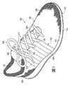
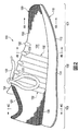
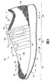
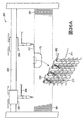
A
参照のために、履物100は足先領域101と中足領域102とかかと領域103との大略的に3つの領域に分割してもよい。足先領域101は、大略的に、つま先、および中足骨と指骨とを接続する関節に対応する履物100の部分を含んでいる。中足領域102は、大略的に、足のアーチ区域に対応する履物100の部分を含んでいる。かかと領域103は、大略的に、踵骨を含めて足の後部に対応している。履物100は外側側部104および内側側部105も含んでおり、領域101〜103のそれぞれを通って延びており、履物100の両側に対応する。より具体的には、外側側部104は足の外側部位に対応し(つまり、反対の足から遠ざかる方を向く面)、内側側部105は足の内側部位に対応する(つまり、反対の足の方を向く面)。領域101〜103および側部104〜105は履物100の厳密な区域を区切ることを意図していない。むしろ、領域101〜103および側部104〜105は、以下の説明の助けになるように、履物100の大略的な区域を表すことを意図している。履物100に加えて、領域101〜103および側部104〜105はソール構造110、アッパー120およびそれらの個々の要素に適用してもよい。
For reference, the
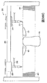
ソール構造110はアッパー120に固定されていて、履物100を履いたときに足と地面との間に延びる。ソール構造110の主要な要素はミッドソール111、アウトソール112、および中敷き113である。ミッドソール111はアッパー120の下面に固定されて、歩いているとき、走っているとき、または他の歩行活動中に足と地面との間で圧縮されると、地面の反力を弱める(つまり、クッション材となる)圧縮可能なポリマー発泡体要素(例、ポリウレタンまたはエチルビニルアセテート発泡体)から形成してもよい。さらなる構成では、ミッドソール111は、さらに力を弱め、安定性を高め、足の動きに影響を与えるプレート、モデレータ、液体充填チャンバ、ラスティング要素、もしくはモーションコントロール部材を組み込んでもよく、またはミッドソール21は主に液体充填チャンバから形成してもよい。アウトソール112はミッドソール111の下面に固定されて、牽引力を付与するように織られた耐摩耗性のゴム材料から形成してもよい。中敷き113はアッパー120内に配置されていて、足の下面の下に延びて履物100の快適性を高めるように位置付けられている。ソール構造110のこの構成はアッパー120と接続して使用してもよいソール構造の一実施例を提供しているが、ソール構造110のさまざまな他の従来の構成または従来にない構成も利用してもよい。したがって、ソール構造110またはアッパー120とともに利用されるソール構造の特徴は大幅に変わってもよい。
The
アッパー120は、ソール構造110に対して足を受け入れて固定するための空洞を履物100内に画定する。空洞は足を収容するような形状にされており、足の外側側部に沿い、足の内側側部に沿い、足の上、かかとの周り、さらに足の下に延びている。空洞へのアクセスは、少なくともかかと領域103に配置されている足首開口部121により提供される。締めひも122がアッパー120のさまざまな開口123を通って延びており、着用者がアッパー120の寸法を調整してさまざまなプロポーションの足を収容できるようにする。さらに具体的には、締めひも122は着用者が足の周りにアッパー120を締めつけることができるようにし、締めひも122は着用者の空洞からの(つまり、足首開口部121を通して)足の出し入れを容易にするために、アッパー120を緩めることができる。さらに、アッパー120は締めひも122および開口123の下に延びて履物100の快適性を高めるベロ124を含んでいる。さらなる構成では、アッパー120は、(a)かかと領域103に安定性を高めるヒールカウンタ、(b)足先領域101に耐摩耗性材料で形成されているつま先ガード、ならびに(c)ロゴ、商標、および注意書きおよび材料情報を記載した札などの追加要素を含んでいてもよい。
従来の履物のアッパーの多くは、例えば縫製または接着により接合されている多数の材料要素(例、織物、ポリマー発泡体、ポリマーシート、革、合成皮革)から形成されている。対して、アッパー120の大部分はニット構成要素130から形成されており、領域101〜103のそれぞれを通って、外側側部104および内側側部105の両方に沿い、足先領域101の上、さらにかかと領域103の周りに延びている。くわえて、ニット構成要素130はアッパー120の外面および対向する内面の両方の部分を形成している。このように、ニット構成要素130はアッパー120内に空洞の少なくとも一部を画成している。いくつかの構成では、ニット構成要素130は足の下にも延びていてもよい。しかし、図4A〜図4Cを参照すると、ストローベル式中敷き125がニット構成要素130およびミッドソール111の上面に固定されており、それにより中敷き113の下に延びているアッパー120の一部を形成している。
Many conventional footwear uppers are formed from a number of material elements (e.g., fabrics, polymer foams, polymer sheets, leather, synthetic leather) joined together, for example, by sewing or gluing. In contrast, most of the upper 120 is formed from a
〈ニット構成要素の構成〉
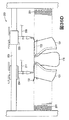
図5および図6では、ニット構成要素130は履物100の残りの部分とは別に図示されている。ニット構成要素130は一体ニット構造から形成されている。本明細書で利用するように、ニット構成要素(例、ニット構成要素130)は、編みプロセスでワンピース要素として形成されると、「一体ニット構造」から形成されていると定義される。すなわち、編みプロセスは、大幅な追加の製造工程またはプロセスの必要なく、ニット構成要素130のさまざまな特徴および構造を実質的に形成する。ニット構成要素130の部分は編みプロセス後に互いに接合してもよいが(例、ニット構成要素130の縁部を互いに接合する)、ニット構成要素130はワンピースニット要素として形成されているため、依然として一体ニット構造から形成されたままである。また、ニット構成要素130は、編みプロセス後に他の要素(例、締めひも122、ベロ124、ロゴ、商標、注意書きおよび材料情報を記載した札)を追加しても、依然として一体ニット構造から形成されたままである。
<Configuration of knit components>
5 and 6, the
ニット構成要素130の主要な要素はニット要素131およびインレイストランド132である。ニット要素131は、さまざまなコースおよびウェールを画成する複数の互いにかみ合うループを形成するように操作される(例、編み機を用いて)少なくとも1本のヤーンから形成されている。すなわち、ニット要素131はニット布地の構造を有する。インレイストランド132はニット要素131を通って延びており、ニット要素131内のさまざまなループの間を通っている。インレイストランド132は一般にニット要素131内のコースに沿って延びているが、インレイストランド132はニット要素131のウェールに沿って延びていてもよい。インレイストランド132の利点は、支持、安定性および構造を提供することが含まれる。例えば、インレイストランド132はアッパー120を足の周りに固定するのを助け、アッパー120の区域での変形を制限し(例、耐伸張性を付与する)、締めひも122と連動して履物100のフィット性を高める。
The main elements of the
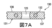
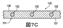
ニット要素131は、周縁部133、1対のかかと縁部134および内側縁部135により輪郭が描かれる略U字形の構成を有する。履物100に組み込まれるとき、周縁部133はミッドソール111の上面に載せて、ストローベル式中敷き125に接合される。かかと縁部134は互いに接合されており、かかと領域103に垂直に延びている。履物100のいくつかの構成では、材料要素はかかと縁部134間の縫い目を覆って、縫い目を補強するとともに、履物100の美観的な魅力を高めてもよい。内側縁部135は足首開口部121を形成して、締めひも122、開口123およびベロ124が配置される区域まで前方に延びている。くわえて、ニット要素131は第1面136と対向する第2面137とを有する。第1面136はアッパー120の外面の一部を形成するのに対し、第2面137はアッパー120の内面の一部を形成するので、アッパー120内に空洞の少なくとも一部を画成する。
The
前述したように、インレイストランド132はニット要素131を通って延びており、ニット要素131内のさまざまなループの間を通過している。より具体的には、インレイストランド132はニット要素131のニット構造内に配置されており、これは図7A〜図7Dに図示するように、インレイストランド132の区域で、面136および面137との間に単一の布地層の構成を有していてもよい。そのため、ニット構成要素130が履物100に組み込まれるとき、インレイストランド132はアッパー120の外面と内面との間に配置される。いくつかの構成では、インレイストランド132の部分は可視でき、または面136および137の一方もしくは両方に露出していてもよい。例えば、インレイストランド132は面136および137の一方に載せてもよく、またはニット要素131はインレイストランドが通過する凹みもしくは開口を形成していてもよい。インレイストランド132を面136と面137との間に配置させる利点は、ニット要素131がインレイストランド132の擦過およびスナッギングを保護することである。
As described above, the
図5および図6を参照すると、インレイストランド132は周縁部133から内側縁部135に向かって、1つの開口123の側部に隣接して、開口123の少なくとも一部を周って、反対側まで、さらに周縁部133に戻るように繰り返し延びている。ニット構成要素130が履物100に組み込まれるとき、ニット要素131はアッパー120のスロート区域(つまり、締めひも122、開口123およびベロ124が配置されている場所)から、アッパー120の下側区域(つまり、ニット要素131がソール構造110と合わさる場所)まで延びている。この構成では、インレイストランド132もスロート区域から下側区域まで延びている。より具体的には、インレイストランドはスロート区域から下側区域までニット要素131を繰り返し通過している。
Referring to FIGS. 5 and 6, the
ニット要素131はさまざまな方法で形成してもよいが、ニット構造のコースはインレイストランド132と略同じ方向に延びている。すなわち、コースはスロート区域と下側区域との間に延びる方向に延びていてもよい。このように、インレイストランド132の大部分はニット要素131内のコースに沿って延びている。しかし、開口123に隣接する区域では、インレイストランド132はニット要素131内のウェールに沿って延びていてもよい。より具体的には、内側縁部135に平行なインレイストランド132の区間はウェールに沿って延びていてもよい。
The
前述したように、インレイストランド132はニット要素131を繰り返し通過している。図5および図6を参照すると、インレイストランド132は周縁部133でもニット要素131を出てから、周縁部133の別の場所でニット要素131に再進入することを繰り返しており、それによって周縁部133に沿ってループを形成している。この構成の利点は、スロート区域と下側区域との間に延びているインレイストランド132の各区間を、履物100の製造プロセス中に独立して緊張、弛緩またはその他調整してもよいことである。すなわち、ソール構造110をアッパー120に固定する前に、インレイストランド132の区間を適切な張力になるように独立して調整してもよい。
As described above, the
ニット要素131と比べて、インレイストランド132はより大きな耐伸張性を呈してもよい。すなわち、インレイストランド132はニット要素131よりも伸張しなくてもよい。インレイストランド132の多数の区間がアッパー120のスロート区域からアッパー120の下側区域まで延びていることを考えると、インレイストランド132はスロート区域と下側区域との間のアッパー120の部分に耐伸張性を付与する。また、締めひも122に張力を加えることでインレイストランド132に張力を付与し、それによりスロート区域と下側区域との間のアッパー120の部分を足に当てるように誘導してもよい。このように、インレイストランド132は締めひも122と連動して、履物100のフィット性を高める。
Compared to the
ニット要素131は、アッパー120の個別区域に異なる特性を付与するさまざまな種類のヤーンを組み込んでもよい。すなわち、ニット要素131のある区域を第1特性セットを付与する第1種のヤーンから形成してもよく、ニット要素131の別の区域を第2特性セットを付与する第2種のヤーンから形成してもよい。この構成では、ニット要素131の異なる区域に特定のヤーンを選択することにより、アッパー120全体で特性を変えてもよい。特定の種類のヤーンがニット要素131の一区域に付与することになる特性は、ヤーン内のさまざまなフィラメントおよびファイバを形成している材料に部分的に依存する。例えば、綿は柔らかな手触り、自然な美観、および生物分解性を提供する。エラステインおよび伸縮性ポリエステルは、それぞれ実質的な伸縮性および復元力を提供し、伸縮性ポリエステルはリサイクル可能性も提供する。レーヨンは光沢に優れ、吸湿性を提供する。ウールも断熱性および生物分解性に加えて、高い吸湿性を提供する。ナイロンは耐久性があり耐擦過性材料で、比較的強度が高い。ポリエステルは疎水性の材料で、比較的高い耐久性も提供する。材料に加えて、ニット要素131のために選択されるヤーンの他の側面がアッパー120の特性に影響することもある。例えば、ニット要素131を形成するヤーンは単繊維または多繊維ヤーンであってもよい。ヤーンはそれぞれ異なる材料から形成される個別のフィラメントを含んでいてもよい。くわえて、ヤーンは、鞘芯構成を有するフィラメントまたは異なる材料から形成される2種類のフィラメントを用いた複合ヤーンなど、それぞれ2以上の異なる材料から形成されるフィラメントを含んでいてもよい。撚りおよび捲縮の程度を異ならせること、ならびにデニールを異ならせることでもアッパー120の特性に影響を与えてもよい。したがって、ヤーンを形成する材料およびヤーンの他の側面の両方を、アッパー120の個別区域にさまざまな特性を付与するために選択してもよい。
The
ニット要素131を形成するヤーンと同様、インレイストランド132の構造も大幅に変化させてもよい。ヤーンに加えて、インレイストランド132は、例えば、フィラメント(例、単繊維)、スレッド、ロープ、帯、ケーブル、または鎖の構成を有していてもよい。ニット要素131を形成するヤーンと比べて、インレイストランド132の厚みは厚くてもよい。いくつかの構成では、インレイストランド132はニット要素131のヤーンよりも大幅に厚い厚みを有してもよい。インレイストランド132の断面形状は丸形でもよいが、三角形、正方形、長方形、楕円形または不規則な形状を利用してもよい。また、インレイストランド132を形成する材料は、綿、エラステイン、ポリエステル、レーヨン、ウールおよびナイロンなど、ニット要素131内のヤーンの材料のいずれを含んでいてもよい。前述したように、インレイストランド132はニット要素131よりも大きい耐伸縮性を示してもよい。このように、インレイストランド132に適した材料は、ガラス、アラミド(例、パラアラミドおよびメタアラミド)、超高分子量ポリエチレン、ならびに液晶ポリマーを含め、高引張り強さの用途で利用されるさまざまな工学的フィラメントを含んでいてもよい。別の例として、インレイストランド132としてポリエステル製組糸を利用してもよい。
Similar to the yarn forming the
ニット構成要素130の一部に適した構成の実施例を図8Aに図示している。この構成では、ニット要素131は複数の水平コースおよび垂直ウェールを画定する複数の互いにかみ合うループを形成するヤーン138を含んでいる。インレイストランド132はコースの1つに沿って延びており、(a)ヤーン138から形成されるループの背後と(b)ヤーン138から形成されるループの前とに交互に配置されている。実際には、インレイストランド132はニット要素131によって形成される構造を縫うように通っている。この構成ではヤーン138はコースのそれぞれを形成するが、追加のヤーンが1以上のコースを形成してもよく、または1以上のコースの一部を形成してもよい。
An example of a configuration suitable for a portion of the
ニット構成要素130の一部に適した構成の別の実施例を図8Bに図示している。この構成では、ニット要素131はヤーン138と別のヤーン139とを含んでいる。ヤーン138および139は添え糸編みされて、複数の水平コースおよび垂直ウェールを画定する複数の互いにかみ合うループを共同で形成している。すなわち、ヤーン138および139は互いに平行に走行している。図8Aの構成と同様に、インレイストランド132はコースのうちの1つに沿って延びており、(a)ヤーン138および139から形成されるループの背後と、(b)ヤーン138および139から形成されるループの前との間に交互に配置されている。この構成の利点は、ヤーン138および139のそれぞれの特性がニット構成要素130のこの区域に存在してもよいことである。例えば、ヤーン138の色が主にニット要素131のさまざまな編み目の表面に現れ、ヤーン139の色が主にニット要素131のさまざまな編み目の裏面に現れるとすれば、ヤーン138および139は異なる色を有していてもよい。別の実施例として、ヤーン138が主に第1面136に現れ、ヤーン139が主に第2面137に現れるとすれば、ヤーン139はヤーン138よりも柔らかく、足に対してより快適なヤーンから形成してもよい。
Another embodiment of a configuration suitable for a portion of the
図8Bの構成に続くと、ヤーン138は熱硬化性ポリマーおよび天然繊維(例、綿、ウール、絹)のうちの少なくとも1つから形成してもよく、一方ヤーン139は熱可塑性ポリマー材料から形成してもよい。一般に、熱可塑性ポリマー材料は加熱すると溶け、冷却すると固体状態に戻る。より具体的には、熱可塑性ポリマー材料は十分な熱を受けると固体状態から軟化した状態または液体状態に遷移し、さらに熱可塑性ポリマー材料は十分に冷却すると軟化した状態または液体状態から固体状態に遷移する。このように、熱可塑性ポリマー材料は2つの物体または要素を接合するためにしばしば使用される。この場合、ヤーン139は、例えば、(a)ヤーン138のある部分をヤーン138の別の部分に、(b)ヤーン138とインレイストランド132とを互いに、または(c)別の要素(例、ロゴ、商標、ならびに注意書きおよび材料情報を記載した札)をニット構成要素130に接合するために利用してもよい。このように、ヤーン139は、ニット構成要素130の部分を互いに融着またはその他接合するために使用してもよいのであれば、融着性ヤーンと考えてもよい。また、ヤーン138は、一般にニット構成要素130の部分を互いに融着またはその他接合できる材料から形成されていないのであれば、非融着性ヤーンと考えてもよい。すなわち、ヤーン138は非融着性ヤーンとしてもよく、一方ヤーン139は融着性ヤーンとしてもよい。ニット構成要素130のいくつかの構成では、ヤーン138(つまり、非融着性ヤーン)は実質的に熱硬化性ポリエステル材料から形成してもよく、ヤーン139(つまり、融着性ヤーン)は少なくとも部分的に熱可塑性ポリエステル材料から形成してもよい。
Following the configuration of FIG. 8B, the
添え糸編みしたヤーンの使用はニット構成要素130に利点を付与することがある。ヤーン139を加熱して、ヤーン138およびインレイストランド132に融着する場合、このプロセスはニット構成要素130の構造を剛くまたは堅くする効果を有することがある。また、(a)ヤーン138のある部分をヤーン138の別の部分に、または(b)ヤーン138とインレイストランド132を互いに接合すると、ヤーン138およびインレイストランド132の相対的な位置を固定またはロックする効果を有し、それにより耐伸張性および剛性を付与する。すなわち、ヤーン138の部分はヤーン139と融着しても互いに対して滑らず、それによりニット構造の相対的な動きによるニット要素131のねじれまたは永久的な伸びを防止する。別の利点は、ニット構成要素130の一部が傷んできた、またはヤーン138の1つが切れる場合にほつれを制限することに関わる。また、インレイストランド132はニット要素131に対して滑ることがなく、それによりインレイストランド132の部分がニット要素131から外側に引っ張られるのを防止する。したがって、ニット構成要素130の区域は、ニット要素131内に融着性ヤーンおよび非融着性ヤーンを両方使用することで利益が生まれるであろう。
The use of spliced yarns may provide benefits to the knitted
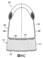
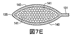
ニット構成要素130の別の側面は、足首開口部121に隣接し、足首開口部121の周りに少なくとも部分的に延びているパッド入り区域に関わる。図7Eを参照すると、パッド入り区域は、一体ニット構造から形成してもよい、重複して少なくとも部分的に同一の広がりをもつ2つのニット層140と、ニット層140間に延びている複数のフローティングヤーン141とによって形成されている。ニット層140の側部または縁部は互いに固定されているが、中央区域は一般に固定されていない。このように、ニット層140はチューブまたは筒状構造を効果的に形成し、フローティングヤーン141は筒状構造を貫通するようにニット層140間に配置され、または挿入されてもよい。すなわち、フローティングヤーン141はニット層140間に延びており、ニット層140の表面に略平行で、さらにニット層140間を貫通してその内部空間を埋める。ニット要素131の大部分は機械操作されるヤーンから形成して、互いにかみ合うループを形成するが、フローティングヤーン141は一般にニット層140間の内部空間内で自由であり、またはその他挿入されている。追加事項として、ニット層140は少なくとも部分的にストレッチヤーンから形成してもよい。この構成の利点は、ニット層がフローティングヤーン141を効果的に圧縮し、足首開口部121に隣接するパッド入り区域に弾性性質を提供することである。すなわち、ニット層140内のストレッチヤーンはニット構成要素130を形成する編みプロセス中に緊張状態で配置され、それによりニット層140をフローティングヤーン141を圧縮するように誘導してもよい。ストレッチヤーンの伸縮性の程度は大幅に変えてもよいが、ニット構成要素130の多くの構成においてストレッチヤーンは少なくとも百パーセント伸縮してもよい。
Another side of the knitted
フローティングヤーン141の存在は足首開口部121に隣接するパッド入り区域に圧縮可能な性質を付与し、それにより履物100の足首開口部121の区域の快適性を高める。多くの従来の履物製品はポリマー発泡体要素または他の圧縮可能な材料を足首開口部に隣接する区域に組み込んでいる。従来の履物製品に対し、一体ニット構造から形成するニット構成要素130の部分はニット構成要素130の残りの部分とともに、足首開口部121に隣接するパッド入り区域を形成してもよい。履物100のさらなる構成において、ニット構成要素130の他の区域に同様なパッド入り区域を配置してもよい。例えば、関節にパッドを付与するために、中足骨と近位指骨との間の関節に対応する区域として同様なパッド入り区域を配置してもよい。あるいは、アッパー120の区域にある程度のパッドを付与するために、テリーループ構造を利用してもよい。
The presence of the floating
上記の説明に基づき、ニット構成要素130はアッパー120にさまざまな特徴を付与する。また、ニット構成要素130はいくつかの従来のアッパー構成より優れたさまざまな利点を提供する。前述したように、従来の履物のアッパーは、例えば縫製または接着により接合される複数の材料要素(例、布地、ポリマー発泡体、ポリマーシート、革、合成皮革)から形成されている。アッパーに組み込まれる材料要素の数および種類が増えるほど、材料要素を輸送、保管、切断および接合することに関連する時間および費用も増大するであろう。切断および縫製プロセスから出る廃材も、アッパーに組み込まれる材料要素の数および種類が増えるほど、より多く蓄積する。また、材料要素の数が多いアッパーは、種類および数が少ない材料要素から形成されているアッパーよりもリサイクルが難しくなるであろう。そのため、アッパーに利用される材料要素の数を減らすことにより、アッパーの製造効率およびリサイクル性を高めながら廃棄物が減少するであろう。このために、ニット構成要素130は、製造効率を高め、廃棄物を減少し、リサイクル性を簡単にしながら、アッパー120の実質的な部分を形成する。
Based on the above description, the
〈さらなるニット構成要素の構成〉
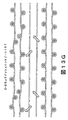
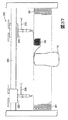
ニット構成要素150が図9および図10に図示されており、履物100のニット構成要素130の代わりに利用してもよい。ニット構成要素150の主要な要素は、ニット要素151およびインレイストランド152である。ニット要素151は操作される(例、編み機を用いて)少なくとも1本のヤーンから形成され、さまざまなコースおよびウェールを画定する複数の互いにかみ合うループを形成する。すなわち、ニット要素151はニット布地の構造を有する。インレイストランド152はニット要素151を通って延びており、ニット要素151内のさまざまなループの間を通過している。インレイストランド152は大略的にニット要素151内のコースに沿って延びているが、インレイストランド152はニット要素151内のウェールに沿って延びていてもよい。インレイストランド132と同様、インレイストランド152は耐伸張性を付与し、履物100に組み込まれると、締めひも122と連動して履物100のフィット性を高める。
<Configuration of further knit components>
A
ニット要素151は、周縁部153、1対のかかと縁部154および内側縁部155によって輪郭が描かれる略U字形の構成を有する。くわえて、ニット要素151は第1面156および対向する第2面157を有する。第1面156はアッパー120の外面の一部を形成してもよく、一方、第2面157はアッパー120の内面の一部を形成してもよいため、アッパー120内に空洞の少なくとも一部を画定する。多くの構成では、ニット要素151はインレイストランド152の区域で単一の布地層の構成を有していてもよい。すなわち、ニット要素151は面156と面157との間の単一の布地層であってもよい。くわえて、ニット要素151は複数の開口158を画定する。
The
インレイストランド132と同様に、インレイストランド152は周縁部153から内側縁部155に向かって、少なくとも部分的に開口158の1つを周って、さらに周縁部153に戻るように繰り返し延びている。しかし、インレイストランド132と対照的に、インレイストランド152のある部分は後方に角度をつけて曲がり、かかと縁部154まで延びている。より具体的には、最後方の開口158に関連するインレイストランド152の部分は、かかと縁部154の1つから内側縁部155に向かって、少なくとも部分的に最後方の開口158を周って、さらにかかと縁部154の1つに戻るように延びている。さらに、インレイストランド152のいくつかの部分は開口158の1つの周りに延びていない。さらに具体的には、インレイストランド152のいくつかの区画は内側縁部155に向かって延びており、開口158の1つに隣接する区域で方向転換して、周縁部153またはかかと縁部154の1つに向かって戻るように延びている。
Similar to the
ニット要素151はさまざまな方法で形成してもよいが、ニット構造のコースは大略的にインレイストランド152と同じ方向に延びている。しかし、開口158に隣接する区域では、インレイストランド152はニット要素151内のウェールに沿って延びていてもよい。より具体的には、内側縁部155に平行なインレイストランド152の区画はウェールに沿って延びていてもよい。
Although the
ニット要素151と比べ、インレイストランド152はより大きな耐伸張性を示してもよい。すなわち、インレイストランド152はニット要素151よりも伸張しなくてもよい。インレイストランド152の多数の区画がニット要素151を通って延びているのであれば、インレイストランド152はスロート区域と下側区域との間のアッパー120の部分に耐伸張性を付与してもよい。また、締めひも122に張力をかけることでインレイストランド152に張力を付与し、それによってスロート区域と下側区域との間のアッパー120の部分を足に当てるように誘導してもよい。さらに、インレイストランド152の多数の区画がかかと縁部154に向かって延びているのであれば、インレイストランド152はアッパー120のかかと領域103の部分に耐伸張性を付与してもよい。また、締めひも122に張力をかけることで、かかと領域103のアッパー120の部分が足に当たるように誘導してもよい。このように、インレイストランド152は締めひも122と連動して、履物100のフィット性を高める。
Compared to the
ニット要素151は、ニット要素131について上記説明したさまざまな種類のヤーンのいずれを組み込んでもよい。インレイストランド152も、インレイストランド132について上記説明した構成および材料のいずれから形成してもよい。さらに、図8Aおよび図8Bに関して説明したさまざまなニット構成も、ニット構成要素150で利用してもよい。より具体的には、ニット要素151は単一のヤーン、2種類を添え糸編みしたヤーン、または融着性ヤーンおよび非融着性ヤーンから形成される区域を有していてもよく、融着性ヤーンが、(a)非融着性ヤーンのある部分を非融着性ヤーンの別の部分に、または(b)非融着性ヤーンとインレイストランド152を互いに接合する。
The
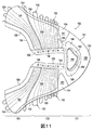
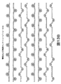
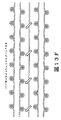
ニット要素131の大部分は、比較的テクスチャード加工していない布地、共通または単一ニット構造(例、筒状ニット構造)から形成されているように図示されている。対して、ニット要素151はニット構成要素150の異なる区域に特定の特性および利点を付与するさまざまなニット構造を組み込んでいる。また、さまざまなヤーンの種類をニット構造と組み合わせることにより、ニット構成要素150はアッパー120の異なる区域に幅広い特性を付与してもよい。図11を参照すると、ニット構成要素150の模式図は異なるニット構造を有するさまざまなゾーン160〜169を示しており、そのそれぞれをここで詳細に説明していく。参照のために、図11では、領域101〜103および側部104および105のそれぞれは、ニット構成要素150が履物100に組み込まれたときに、ニットゾーン160〜169の位置の参照となるように示している。
Most of the
筒状ニットゾーン160は、周縁部153の大部分に沿って、側部104および105の両方の領域101〜103のそれぞれを通って延びている。筒状ニットゾーン160は、領域101および102の境界にほぼ配置されている区域で側部104および105のそれぞれから内側にも延びて、内側縁部155の前方部分を形成している。筒状ニットゾーン160は比較的テクスチャード加工していないニット構成を形成している。図12Aを参照すると、筒状ニットゾーン160の区域を通る断面が図示されており、面156および157は互いに実質的に平行である。筒状ニットゾーン160は履物100にさまざまな利点を付与する。例えば、筒状ニットゾーン160は、特に筒状ニットゾーン160のヤーンを融着性ヤーンで添え糸編みすると、他のいくつかのニット構造よりも耐久性および耐摩耗性がある。さらに、筒状ニットゾーン160の比較的テクスチャード加工していない性質はストローベル式中敷き125を周縁部153に接合するプロセスを簡単にする。すなわち、周縁部153に沿って配置されている筒状ニットゾーン160の部分は、履物100のラスティングプロセスを容易にする。参照のために、図13Aは筒状ニットゾーン160を編みプロセスで形成する態様のループ図を図示している。
The cylindrical knitted
2つのストレッチニットゾーン161が周縁部153から内側に延びており、足の中足骨と近位指骨との間の関節の位置に対応するように配置されている。すなわち、ストレッチゾーンは、領域101および102の境界にほぼ配置されている区域で周縁部から内側に延びている。筒状ニットゾーン160と同様に、ストレッチニットゾーン161のニット構成は筒状ニット構造にしてもよい。しかし、筒状ニットゾーン160と対照的に、ストレッチニットゾーン161はニット構成要素150に伸縮性および復元性を付与するストレッチヤーンから形成されている。ストレッチヤーンの伸縮性の程度は大幅に変わってもよいが、ニット構成要素150の多くの構成においてストレッチヤーンは少なくとも百パーセント伸縮してもよい。
Two
筒状の両面(インターロック)タックニットゾーン162が、少なくとも中足領域102の内側縁部155の部分に沿って延びている。筒状の両面タックニットゾーン162も比較的テクスチャード加工していないニット構成を形成するが、筒状ニットゾーン160よりも厚い厚みを有する。断面では、筒状の両面タックニットゾーン162は図12Aと類似しており、面156および157は互いに実質的に平行である。筒状の両面タックニットゾーン162は履物100にさまざまな利点を付与する。例えば、筒状の両面タックニットゾーン162は他のいくつかのニット構造よりも耐伸張性があり、締めひも122が筒状の両面タックニットゾーン162およびインレイストランド152に張力をかけるとき有利である。参照のために、図13Bは、筒状の両面タックニットゾーン162を編みプロセスで形成する態様のループ図を図示している。
A cylindrical double-sided (interlock)
1×1メッシュのニットゾーン163が足先領域101に配置されて、周縁部153から内側に離れている。1×1メッシュのニットゾーンは、図12Bに図示するように、C字形の構成を有し、ニット要素151を通って、第1面156から第2面157まで延びている複数の開口を形成している。開口はニット構成要素150の通気性を高め、空気をアッパー120に進入させ、水分をアッパー120から逃がすことができる。参照のために、図13Cは、1×1メッシュのニットゾーン163を編みプロセスで形成する態様のループ図を図示している。
A 1 × 1
2×2メッシュのニットゾーン164が1×1メッシュのニットゾーン163に隣接して延びている。1×1メッシュのニットゾーン163と比べて、2×2メッシュのニットゾーン164はより大きな開口を形成し、ニット構成要素150の通気性をさらに高めるであろう。参照のために、図13Dは、2×2メッシュのニットゾーン164を編みプロセスで形成する態様のループ図を図示している。
A 2 × 2
3×2メッシュのニットゾーン165が2×2メッシュのニットゾーン164内に配置されており、別の3×2メッシュのニットゾーン165がストレッチゾーン161の1つに隣接して配置されている。1×1メッシュのニットゾーン163および2×2メッシュのニットゾーン164と比べて、3×2メッシュのニットゾーン165はさらに大きな開口を形成し、ニット構成要素150の通気性をさらに高めるであろう。参照のために、図13Eは、3×2メッシュのニットゾーン165を編みプロセスで形成する態様のループ図を図示している。
A 3 × 2
1×1モックメッシュのニットゾーン166が足先領域101に配置されており、1×1メッシュのニットゾーン163の周りに延びている。ニット要素151を通る開口を形成するメッシュのニットゾーン163〜165と対照的に、図12Cに図示するように、1×1モックメッシュのニットゾーン166は第1面156に凹みを形成する。履物100の美観を向上させることに加えて、1×1モックメッシュのニットゾーン166はニット構成要素150の柔軟性を高めるとともに、全体の質量を減少させる。参照のために、図13Fは、1×1モックメッシュのニットゾーン166を編みプロセスで形成する態様のループ図を図示している。
A 1 × 1 mock
2つの2×2モックメッシュのニットゾーン167がかかと領域103に、かかと縁部154に隣接して配置されている。1×1モックメッシュのニットゾーン166と比べて、2×2モックメッシュのニットゾーン167は第1面156により大きな凹みを形成する。図12Dに図示するように、インレイストランド152が2×2モックメッシュのニットゾーン167の凹みを通って延びている区域では、インレイストランド152は見えて、凹みの下側区域に露出されるであろう。参照のために、図13Gは、2×2モックメッシュのニットゾーン167を編みプロセスで形成する態様のループ図を図示している。
Two 2 × 2 mock
2つの2×2ハイブリッドニットゾーン168が中足領域102に、2×2モックメッシュのニットゾーン167の前方に配置されている。2×2ハイブリッドニットゾーン168は2×2メッシュのニットゾーン164および2×2モックメッシュのニットゾーン167の特徴を共有する。より具体的には、2×2ハイブリッドニットゾーン168は2×2メッシュのニットゾーン164のサイズおよび構成を有する開口を形成するとともに、2×2ハイブリッドニットゾーン168は2×2モックメッシュのニットゾーン167のサイズおよび構成を有する凹みを形成する。図12Eに図示するように、インレイストランド152が2×2ハイブリッドニットゾーン168の凹みを通って延びている区域では、インレイストランド152は見えて露出している。参照のために、図13Hは、2×2ハイブリッドニットゾーン168を編みプロセスで形成する態様のループ図を図示している。
Two 2 × 2
ニット構成要素150は、ニット構成要素130について上記説明した足首開口部121に隣接して、少なくとも部分的に足首開口部121の周りに延びているパッド入り区域の一般構成を有する2つのパッド入りゾーン169を含んでいてもよい。このように、パッド入りゾーン169は、一体ニット構造から形成してもよい2つの重複して少なくとも部分的に同一の広がりをもつニット層と、ニット層の間に延びている複数のフローティングヤーンとによって形成されている。
The
図9および図10との比較から、ニット要素151のテクスチャリングの大部分は、第2面157ではなく、第1面156に配置されていることが明らかになる。すなわち、モックメッシュのニットゾーン166および167により形成される凹み、ならびに2×2ハイブリッドニットゾーン168の凹みは、第1面156に形成される。この構成は履物100の快適性を高めるという利点を有する。より具体的には、この構成は第2面157の比較的テクスチャード加工していない構成を足に当てる。図9と図10とのさらなる比較から、インレイストランド152の部分は第1面156で露出しているが、第2面157では露出していないことが明らかになる。この構成も履物100の快適性を高めるという利点を有する。さらに具体的には、インレイストランド152をニット要素151の一部により足から離すことにより、インレイストランド152が足に接触することはない。
Comparison with FIGS. 9 and 10 reveals that most of the texturing of the
ニット構成要素130の追加構成を図14A〜図14Cに図示している。ニット構成要素130に関係して説明するが、これらの構成のそれぞれに関連する概念はニット構成要素150にも利用してもよい。図14Aを参照すると、インレイストランド132はニット構成要素130にはない。インレイストランド132はニット構成要素130の区域に耐伸張性を付与するが、いくつかの構成ではインレイストランド132からの耐伸張性を必要としなくてもよい。また、いくつかの構成はアッパー120の伸縮性が大きいことから利益を得ることがある。図14Bを参照すると、ニット要素131はニット要素131の残りの部分と合わせて一体ニット構造から形成されて、周縁部133でニット構成要素130の長さに沿って延びている2つのフラップ142を含んでいる。履物100に組み込む場合、フラップ142がストローベル式中敷き125に置き換わってもよい。すなわち、フラップ142は、中敷き113の下に延びて、ミッドソール111の上面に固定されているアッパー120の一部を共同で形成してもよい。図14Cを参照すると、ニット構成要素130は中足領域102に制限されている構成を有する。この構成では、他の材料要素(例、布地、ポリマー発泡体、ポリマーシート、革、合成皮革)を、例えば縫製または接着によりニット構成要素130に接合して、アッパー120を形成してもよい。
Additional configurations of the
上記の説明に基づき、ニット構成要素130および150のそれぞれは、アッパー120に特徴および利点を付与するさまざまな構成を有していてもよい。より具体的には、ニット要素131および151はアッパー120の異なる区域に特定の特性を付与するさまざまなニット構造およびヤーンの種類を組み込んでもよく、インレイストランド132および152はアッパー120の区域に耐伸張性を付与し、締めひも122と連動して履物100のフィット性を高めるように、ニット構造を通って延びていてもよい。
Based on the above description, each of the knit
〈編み機およびフィーダーの構成〉
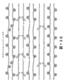
編みは手で行ってもよいが、ニット構成要素の商業的な製造は一般に編み機で行われる。ニット構成要素130および150のいずれの生産にも適した編み機200の一実施例を図15に図示している。編み機200は例示のためにVベッド型横編み機の構成を有しているが、ニット構成要素130および150またはニット構成要素130および150の側面のいずれも他の種類の編み機で生産してもよい。
<Configuration of knitting machine and feeder>
Although knitting may be done by hand, the commercial manufacture of knitted components is typically done on a knitting machine. One embodiment of a
編み機200は互いに対して角度を成すことによりVベッドを形成している2つの針床201を含んでいる。針床201のそれぞれは共通平面上にある複数の個々の針202を含んでいる。すなわち、一方の針床201からの針202は第1平面にあり、他方の針床201からの針202は第2平面にある。第1平面および第2平面(つまり、2つの針床201)は互いに対して角度を成しており、相交わって編み機200の幅の大部分に沿って延びている交差部を形成する。以下さらに詳細に説明するように、針202はそれぞれ後退する第1位置と、延伸する第2位置とを有する。第1位置では、針202は第1平面と第2平面とが相交わる交差部から離れている。しかし、第2位置では、針202は第1平面と第2平面とが相交わる交差部を通過する。
The
1対のレール203が針床201の交差部の上にかつ平行に延びており、複数の標準フィーダー204およびコンビネーションフィーダー220の装着ポイントを提供する。各レール203は2つの側部を有し、そのそれぞれが1つの標準フィーダー204または1つのコンビネーションフィーダー220のいずれかを収容する。このように、編み機200は合計で4つのフィーダー204および220を含んでもよい。図示するように、最前列のレール203は対向する側部に1つのコンビネーションフィーダー220および1つの標準フィーダー204を含み、最後列のレール203は対向する側部に2つの標準フィーダー204を含んでいる。2本のレール203を図示しているが、編み機200のさらなる構成は追加のレール203を組み込んで、より多くのフィーダー204および220の装着ポイントを提供してもよい。
A pair of
キャリッジ205の作用により、フィーダー204および220はレール203および針床201に沿って移動し、それによって針202にヤーンを供給する。図15では、ヤーン206はスプール207によってコンビネーションフィーダー220に供給されている。より具体的には、ヤーン206はスプール207からさまざまなヤーンガイド208、ヤーン引きばね209およびヤーンテンショナー210に延びてから、コンビネーションフィーダー220に進入する。図示していないが、ヤーンをフィーダー204に供給するために、追加スプール207を利用してもよい。
By the action of the
標準フィーダー204は、編み機200などのVベッド型横編み機で従来から利用されている。すなわち、既存の編み機は標準フィーダー204を組み込んでいる。各標準フィーダー204は針202が編み、タック編みおよび浮き編みするために操作するヤーンを供給する能力を有する。比較として、コンビネーションフィーダー220は針202が編み、タック編みおよび浮き編みするヤーン(例、ヤーン206)を供給する能力を有し、コンビネーションフィーダー220はヤーンを挿入する能力を有する。また、コンビネーションフィーダー220はさまざまな異なるストランド(例、フィラメント、スレッド、ロープ、帯、ケーブル、鎖またはヤーン)を挿入する能力を有する。したがって、コンビネーションフィーダー220は各標準フィーダー204よりも優れた汎用性を示す。
The
前述したように、コンビネーションフィーダー220は、ヤーンを編み、タック編みおよび浮き編みすることに加えて、ヤーンまたは他のストランドを挿入するときに利用してもよい。コンビネーションフィーダー220を組み込んでいない従来の編み機もヤーンを挿入してもよい。より具体的には、インレイフィーダーが供給されている従来の編み機もヤーンを挿入してもよい。Vベッド型横編み機の従来のインレイフィーダーは、ヤーンを挿入するために連動する2つの構成要素を含んでいる。インレイフィーダーの構成要素のそれぞれが、2つの隣接するレール上の個別の装着ポイントに固定されており、それによって2つの装着ポイントを占めている。個々の標準フィーダー204は1つの装着ポイントしか占めないが、インレイフィーダーを利用してヤーンをニット構成要素に挿入するときには一般に2つの装着ポイントが占められる。また、コンビネーションフィーダー220は1つの装着ポイントしか占めないが、従来のインレイフィーダーは2つの装着ポイントを占める。
As previously mentioned, the
編み機200が2本のレール203を含んでいるのであれば、編み機200には4つの装着ポイントが利用できる。従来のインレイフィーダーを編み機200に利用した場合、標準フィーダー204には2つの装着ポイントしか利用できないであろう。しかし、編み機200にコンビネーションフィーダー220を使用すると、標準フィーダー204に3つの装着ポイントが利用できる。したがって、ヤーンまたは他のストランドを挿入するときにコンビネーションフィーダー220を利用してもよく、コンビネーションフィーダー220は1つの装着ポイントしか占めないという利点を有する。
If the
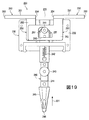
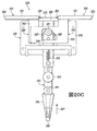
キャリア230、フィーダーアーム240および1対の作動部材250を含むコンビネーションフィーダー220を図16〜図19に個別に図示している。コンビネーションフィーダー220の大半は金属材料(例、スチール、アルミニウム、チタン)から形成してもよいが、キャリア230、フィーダーアーム240および作動部材250の部分は、例えば、ポリマー、セラミックまたは複合材料から形成してもよい。前述したように、コンビネーションフィーダー220は、ヤーンを編み、タック編みおよび浮き編みするときに加えて、ヤーンまたは他のストランドを挿入するときに利用してもよい。特に図16を参照すると、ストランドがコンビネーションフィーダー220に接する態様を例示するために、ヤーン206の一部が図示されている。
A
キャリア230は略矩形の構成を有しており、4本のボルト233で接合されている第1カバー部材231および第2カバー部材232を含んでいる。カバー部材231および232は、フィーダーアーム240および作動部材250の部分が配置されている内部空洞を画定している。キャリア230はフィーダー220をレール230のうちの1本に固定するために、第1カバー部材231から外側に延びている装着要素234も含んでいる。装着要素234の構成は変わることがあるが、図17に図示するように、装着要素234は鳩尾形状を形成する2つの離間した張出区域を含むように図示されている。レール203のうちの1本の逆鳩尾構成が装着要素234の鳩尾形状まで延びて、コンビネーションフィーダー220を編み機200に効果的に接合してもよい。図18に図示するように、第2カバー部材234は中心に位置して細長いスロット235を形成することにも留意するべきである。
The
フィーダーアーム240は、キャリア230(つまり、カバー部材231とカバー部材232との間の空洞)を通って、キャリア230の下側から外側に延びている略細長い構成を有する。他の要素に加えて、フィーダーアーム240は作動ボルト241と、ばね242と、プーリ243と、ループ244と、給糸区域245とを含んでいる。作動ボルト241はフィーダーアーム240から外側に延びており、カバー部材231とカバー部材232との間の空洞内に位置している。図18に図示するように、作動ボルト241の片側は第2カバー部材232のスロット235内にも配置されている。ばね242はキャリア230およびフィーダーアーム240に固定されている、より具体的には、ばね242の一端がキャリア230に固定されており、ばね242の他端がフィーダーアーム240に固定されている。プーリ243、ループ244および給糸区域245がフィーダーアーム240に存在して、ヤーン206または別のストランドと接する。また、プーリ243、ループ244および給糸区域245は、ヤーン206または別のストランドがコンビネーションフィーダー220をスムーズに通過することを確実にし、それによって針202に確実に供給されるように構成されている。再び図16を参照すると、ヤーン206はプーリ243を周り、ループ244を通って、給糸区域245に延びている。くわえて、ヤーン206は、フィーダーアーム240の末端領域である給糸先端部246から延びて、さらに針202に供給される。
The
作動部材250のそれぞれはアーム251およびプレート252を含んでいる。作動部材250の多くの構成では、各アーム251はプレート252の1枚とともにワンピース要素として形成されている。アーム251はキャリア230の外側かつキャリア230の上側に配置されているが、プレート252はキャリア250内に配置されている。アーム251のそれぞれは外側端253および反対の内側端254を画成する細長い構成を有し、アーム251は両内側端254の間の空間255を画成するように位置付けられている。すなわち、アーム251は互いに離間している。プレート252は略平面構成を有する。図19を参照すると、プレート252のそれぞれは傾斜縁部257を備える開口256を画定する。また、フィーダーアーム240の作動ボルト241が各開口256に延びている。
Each
前述したコンビネーションフィーダー220の構成は、フィーダーアーム240の並進運動を容易にする構造を提供する。以下さらに詳細に述べるように、フィーダーアーム240の並進運動は給糸先端部246を針床201の交差部の上または下の位置に選択的に位置付ける。すなわち、給糸先端部246は針床201の交差部を通って往復運動する能力を有する。フィーダーアーム240の並進運動の利点は、コンビネーションフィーダー220が、(a)給糸先端部246が針床201の交差部の上に位置付けられるとき、編み、タック編みおよび浮き編みをするためにヤーン206を供給する、ならびに(b)給糸先端部246が針床201の交差部の下に位置付けられるとき、挿入するためにヤーン206または別のストランドを供給することである。また、フィーダーアーム240はコンビネーションフィーダー220が利用されている態様によって2つの位置の間を往復運動する。
The configuration of the
針床201の交差部を往復運動する際、フィーダーアーム240は後退位置から延伸位置まで並進する。後退位置にあるとき、給糸先端部246は針床201の交差部の上に位置付けられる。延伸位置にあるとき、給糸先端部246は針床201の交差部の下に位置付けられる。フィーダーアーム240が延伸位置にあるときよりもフィーダーアーム240が後退位置にあるときの方が、給糸先端部246はキャリア230に近い。同様に、フィーダーアーム240が後退位置にあるときよりもフィーダーアーム240が延伸位置にあるときの方が、給糸先端部246はキャリア230から遠い。言い換えると、給糸先端部246は延伸位置ではキャリア230から離れるように移動し、給糸先端部246は後退位置にあるときはキャリア230に近づくように移動する。
When reciprocating the intersection of the
図16〜20Cおよび後で説明するさらなる図面において参照のために、矢印221を給糸区域245に隣接して位置付けている。矢印221が上向きまたはキャリア230に向かう方向を指している場合、フィーダーアーム240は後退位置にある。矢印221が下向きまたはキャリア230から遠ざかる方向を指している場合、フィーダーアーム240は延伸位置にある。したがって、矢印221の位置を参照することにより、フィーダーアーム240の位置は容易に確認されるであろう。
For reference in FIGS. 16-20C and further figures described below,
フィーダーアーム240の自然な状態は後退位置である。すなわち、コンビネーションフィーダー220の区域に一切有意な力を加えなければ、フィーダーアームは後退位置にとどまる。例えば、図16〜図19を参照すると、コンビネーションフィーダー220と相互作用する力または他の影響は示されておらず、フィーダーアーム240は後退位置にある。しかし、アーム251の1つに十分な力が加わると、フィーダーアーム240の並進運動が生じる。より具体的には、外側端253の1つに十分な力が加わり、空間255に向けられると、フィーダーアーム240の並進運動が起こる。図20Aおよび図20Bを参照すると、力222は外側端253の1つに作用して空間255に向けられ、フィーダーアーム240が延伸位置に並進したところが示されている。しかし、力222を取り除くと、フィーダーアーム240は後退位置に戻る。図20Cは、内側端254に作用し外側に向いているときの力222を図示しており、フィーダーアーム240は後退位置にとどまっていることにも留意するべきである。
The natural state of the
前述したように、フィーダー204および220は、キャリッジ205の作用のためにレール203および針床201に沿って移動する。より具体的には、キャリッジ205内の駆動ボルトがフィーダー204および220と接触して、フィーダー204および220を針床201に沿って押す。コンビネーションフィーダー220に関して、駆動ボルトは外側端253の1つまたは内側端254の1つのいずれかに接触して、コンビネーションフィーダー220を針床201に沿って押す。駆動ボルトが外側端253の1つに接触すると、フィーダーアーム240は延伸位置に並進して、給糸先端部246が針床201の交差部の下を通る。駆動ボルトが内側端254の1つに接触して空間255内に配置されると、フィーダーアーム240は後退位置にとどまり、給糸先端部246は針床201の交差部の上になる。したがって、キャリッジ205がコンビネーションフィーダー220に接触する区域が、フィーダーアーム240が後退位置にあるか、または延伸位置にあるかを決定する。
As described above, the
ここでコンビネーションフィーダー220の機械的作用を説明する。図19〜図20Bは、第1カバー部材231を取り除いて、キャリア230の空洞内の要素を露出した状態のコンビネーションフィーダー220を図示している。図19と図20Aおよび図20Bを比較することにより、力222がフィーダーアーム240を並進するように誘導する様子が明らかであろう。力222が外側端253の1つに作用すると、作動部材250の1つがフィーダーアーム240の長さに垂直な方向に滑動する。すなわち、作動部材250の1つは図19〜図20Bにおいて水平に滑動する。作動部材250の1つの運動が作動ボルト241を傾斜縁部257の1つに係合させる。作動部材250の運動がフィーダーアーム240の長さに垂直な方向に規制されるのであれば、作動ボルト241は傾斜縁部257に対して回転または滑動し、フィーダーアーム240を延伸位置に並進するように誘導する。力222を取り除くと、ばね242がフィーダーアーム240を延伸位置から後退位置に引く。
Here, the mechanical action of the
上記説明に基づくと、コンビネーションフィーダー220は、ヤーンまたは他のストランドが編み、タック編みもしくは浮き編みのために利用されているか、または挿入のために利用されているかに応じて、後退位置と延伸位置とを往復運動する。コンビネーションフィーダー220は、力222の印加がフィーダーアーム240を後退位置から延伸位置に並進させるように誘導し、力222の排除がフィーダーアーム240を延伸位置から後退位置に並進するように誘導する構成を有する。すなわち、コンビネーションフィーダー220は、力222の印加および排除がフィーダーアーム240を針床201の対向する側部の間を往復運動させる構成を有する。一般に、外側端253は作動区域と考えてもよく、フィーダーアーム240の運動を誘導する。コンビネーションフィーダー220のさらなる構成では、作動区域は他の位置にあってもよく、または他の刺激に応答してフィーダーアーム240の運動を誘導してもよい。例えば、作動区域は、フィーダーアーム240の運動を制御するサーボ機構に連結されている電気入力であってもよい。したがって、コンビネーションフィーダー220は、前述した構成と同じ一般的な態様で動作するさまざまな構造を有していてもよい。
Based on the above description, the
〈編みプロセス〉
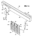
ここで、編み機200がニット構成要素を製造するために動作する態様を詳しく説明していく。また、以下の説明は編みプロセス中のコンビネーションフィーダー220の動作を実証する。図21Aを参照すると、さまざまな針202と、レール203と、標準フィーダー204と、コンビネーションフィーダー220とを含んでいる編み機200の一部が図示されている。コンビネーションフィーダー220はレール203の前側に固定されているが、標準フィーダー204はレール203の後側に固定されている。ヤーン206はコンビネーションフィーダー220を通過し、ヤーン206の一端が給糸先端部246から外側に延びている。ヤーン206が図示されているが、他のあらゆるストランド(例、フィラメント、スレッド、ロープ、帯、ケーブル、鎖またはヤーン)がコンビネーションフィーダー220を通過してもよい。別のヤーン211が標準フィーダー204を通過してニット構成要素260の一部を形成し、ニット構成要素260の最上コースを形成するヤーン211のループが針202の末端に配置されているフックによって保持されている。
<Knitting process>
Here, the manner in which the
本明細書で説明する編みプロセスはニット構成要素260の形成に関係するが、これはニット構成要素130および150と同様なニット構成要素を含め、あらゆるニット構成要素であってもよい。説明のために、図面では、ニット構造を例示できるように、ニット構成要素260の比較的小さな区画しか示していない。また、編み機200およびニット構成要素260のさまざまな要素の縮尺または比率は、編みプロセスをよりよく例証するために拡大している。
Although the knitting process described herein involves the formation of
標準フィーダー204は給糸先端部213を備えるフィーダーアーム212を含んでいる。フィーダーアーム212は給糸先端部213を、(a)針202間の中心になる、および(b)針床201の交差部の上になる位置に位置付ける角度を成している。図22Aはこの構成の模式的な断面図を図示している。針202は異なる平面上にあり、互いに対して角度を成していることに留意する。すなわち、針床201からの針202は異なる平面上にある。針202はそれぞれ第1位置および第2位置を有する。実線で示される第1位置では、針202は後退している。点線で示される第2位置では、針202は延伸している。第1位置で、針202は針床201のある平面が相交わる交差部から離れている。しかし、第2位置では、針202は延びて、針床201のある平面が相交わる交差部を通過している。すなわち、針202は第2位置に延伸すると互いに交差する。給糸先端部213は平面の交差部の上に配置されていることに留意するべきである。この位置で、給糸先端部213は編み、タック編みおよび浮き編みのためにヤーン211を針202に供給する。
The
コンビネーションフィーダー220は、矢印221の向きで明確に示されるように、後退位置にある。フィーダーアーム240はキャリア230から下側に延びて、給糸先端部246を、(a)針202の間の中心になる、および(b)針床201の交差部の上になる位置に位置付ける。図22Bはこの構成の模式的な断面図を図示している。給糸先端部246は図22Aの給糸先端部213と同じ相対的な位置に位置付けられていることに留意する。
The
ここで図21Bを参照すると、標準フィーダー204はレール203に沿って移動し、ヤーン211からニット構成要素260に新たなコースが形成されている。より具体的には、針202は前のコースのループを通してヤーン211の区画を引き、それによって新たなコースを形成する。したがって、標準フィーダー204を針202に沿って移動し、それによって針202がヤーン211を操作して、ヤーン211から追加のループを形成できるようにすることで、ニット構成要素260にコースを追加してもよい。
Referring now to FIG. 21B, the
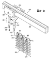
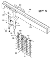
編みプロセスを続けると、図21Cに図示するように、フィーダーアーム240は今度は後退位置から延伸位置に並進する。延伸位置では、フィーダーアーム240はキャリア230から下側に延びて、給糸先端部246を、(a)針202の間の中心になる、および(b)針床201の交差部の下になる位置に位置付ける。図22Cはこの構成の模式的な断面図を図示している。給糸先端部246は、フィーダーアーム240の並進運動のために、図22Bの給糸先端部246の位置の下に位置付けられていることに留意する。
As the knitting process continues, the
ここで図21Dを参照すると、コンビネーションフィーダー220はレール203に沿って移動し、ヤーン206はニット構成要素260のループ間に配置されている。すなわち、ヤーン206はいくつかのループの前かつ他のループの背後に交互パターンで配置されている。また、ヤーン206はある針床201からの針202によって保持されているループの前に配置されるとともに、ヤーン206は他方の針床201からの針202によって保持されているループの背後に配置されている。フィーダーアーム240は、ヤーン206を針床201の交差部の下の区域に置くために、延伸位置にとどまっていることに留意する。こうしてヤーン206を図21Bの標準フィーダー204によって直前に形成されたコース内に効果的に配置する。
Referring now to FIG. 21D, the
ヤーン206をニット構成要素260に完全に挿入するために、図21Eに図示するように、標準フィーダー204はレール203に沿って移動して、ヤーン211から新たなコースを形成する。新たなコースを形成することによって、ヤーン206はニット構成要素260の構造内に効果的に編み込まれ、またはその他の形で統合される。この段階で、フィーダーアーム240も延伸位置から後退位置に並進してもよい。
In order to fully insert the
図21Dおよび図21Eは、レール203に沿ったフィーダー204および220の個別の移動を示している。すなわち、図21Dはレール203に沿ったコンビネーションフィーダー220の第1移動を示し、図21Eはレール203に沿った標準フィーダー204の第2のその後の移動を示している。多くの編みプロセスでは、フィーダー204および220は同時にヤーン206を挿入しながらヤーン211から新たなコースを形成するために効果的に移動してもよい。しかし、ヤーン211から新たなコースを形成する前にヤーン206を位置付けるために、コンビネーションフィーダー220は標準フィーダー204に先立って、または前に移動する。
21D and 21E show the individual movement of
上記説明で概説した一般的な編みプロセスは、インレイストランド132および152をニット要素131および151に配置してもよい態様の実施例を提供する。より具体的には、ニット構成要素130および150は、コンビネーションフィーダー220を利用して、インレイストランド132および152をニット要素131に効果的に挿入することによって形成してもよい。フィーダーアーム240の往復運動を考えると、インレイストランドは新たなコースを形成する前に以前に形成されたコース内に配置してもよい。
The general knitting process outlined in the above description provides an example of how the
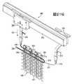
編みプロセスを続けると、図21Fに図示するように、フィーダーアーム240は今度は後退位置から延伸位置に並進する。図21Gに図示するように、次にコンビネーションフィーダー220がレール203に沿って移動して、ヤーン206がニット構成要素260のループ間に配置される。これによりヤーン206は図21Eの標準フィーダー204で形成されたコース内に効果的に配置される。ヤーン206をニット構成要素260に完全に挿入するために、図21Hに図示するように、標準フィーダー204はレール203に沿って移動して、ヤーン211から新たなコースを形成する。新たなコースを形成することにより、ヤーン206はニット構成要素260の構造内に効果的に編み込まれ、またはその他の形で統合される。この段階で、フィーダーアーム240も延伸位置から後退位置に並進してもよい。
As the knitting process continues, the
図21Hを参照すると、ヤーン206は2つのインレイ区画の間にループ214を形成している。上記ニット構成要素130の説明において、インレイストランド132は周縁部133でニット要素131を出てから、周縁部133の別の位置でニット要素131に再進入するのを繰り返し、それによって図5および図6で分かるように、周縁部133に沿ってループを形成することに留意される。ループ214は同様に形成される。すなわち、ループ214はヤーン206がニット構成要素260のニット構造を出てから、ニット構造に再進入するところに形成される。
Referring to FIG. 21H, the
上記説明したように、標準フィーダー204は、針202が編み、タック編みおよび浮き編みするために操作するヤーン(例、ヤーン211)を供給する能力を有する。しかし、コンビネーションフィーダー220はヤーンを挿入するとともに、針202が編み、タック編みまたは浮き編みするヤーン(例、ヤーン206)を供給する能力を有する。編みプロセスの上記の説明は、コンビネーションフィーダー220が延伸位置にあるときにヤーンを挿入する態様を説明している。コンビネーションフィーダー220は後退位置にあるときに、編み、タック編みおよび浮き編みするためのヤーンを供給してもよい。図21Iを参照すると、例えば、コンビネーションフィーダー220は後退位置にあるときにレール203に沿って移動し、後退位置にあるときにニット構成要素260のコースを形成する。したがって、フィーダーアーム240を後退位置と延伸位置との間で往復運動させることにより、コンビネーションフィーダー220は編み、タック編み、浮き編みおよび挿入するためにヤーン206を供給してもよい。そのため、コンビネーションフィーダー220の利点は、標準フィーダー204よりも多くの機能のために利用してもよいヤーンを供給する点においてその汎用性に関係する。
As described above, the
編み、タック編み、浮き編みおよび挿入するためにヤーンを供給するコンビネーションフィーダー220の能力は、フィーダーアーム240の往復運動に基づいている。図22Aおよび図22Bを参照すると、給糸先端部213および246は針220に対して同一の位置にある。このように、フィーダー204および220はともに編み、タック編みおよび浮き編みするためのヤーンを供給してもよい。図22Cを参照すると、給糸先端部246は異なる位置にある。このように、コンビネーションフィーダー220は挿入するためにヤーンまたは他のストランドを供給してもよい。そのため、コンビネーションフィーダー220の利点は、編み、タック編み、浮き編みおよび挿入するために利用してもよいヤーンを供給する点においてその汎用性に関係する。
The ability of the
〈さらなる編みプロセスの考察〉
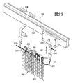
ここで、編みプロセスに関係する追加の側面を説明していく。図23を参照すると、ニット構成要素260の上コースはヤーン206および211の両方から形成されている。
より具体的には、コースの左側はヤーン211で形成されているが、コースの右側はヤーン206から形成されている。さらに、ヤーン206はコースの左側に挿入されている。この構成を形成するために、標準フィーダー204は最初にヤーン211からコースの左側を形成してもよい。次に、フィーダーアーム240が延伸位置にあるときに、コンビネーションフィーダー220はコースの右側にヤーン206を置く。その後、フィーダーアーム240は延伸位置から後退位置に移動して、コースの右側を形成する。したがって、コンビネーションフィーダーはコースのある部分にヤーンを挿入してから、コースの残りの部分を編むためにヤーンを供給してもよい。
<Consideration of further knitting process>
Here, additional aspects related to the knitting process will be described. Referring to FIG. 23, the upper course of the
More specifically, the left side of the course is formed of
図24は、4つのコンビネーションフィーダー220を含んでいる編み機200の構成を図示している。上記説明したように、コンビネーションフィーダー220は、編み、タック編み、浮き編みおよび挿入するためにヤーン(例、ヤーン206)を供給する能力を有する。この汎用性を考えると、標準フィーダー204は編み機200またはさまざまな従来の編み機において複数のコンビネーションフィーダー220に取り替えてもよい。
FIG. 24 illustrates the configuration of a
図8Bは、2本のヤーン138および139を添え糸編みしてニット要素131を形成し、インレイストランド132がニット要素131を通って延びているニット構成要素130の構成を図示している。この構成を形成するために、上記説明した一般的な編みプロセスも利用してもよい。図15に図示するように、編み機200は複数の標準フィーダー204を含んでおり、標準フィーダー204のうちの2つはニット要素131を形成するために利用してもよく、コンビネーションフィーダー220がインレイストランド132を置く。したがって、図21A〜図21Iで上記説明した編みプロセスは、追加ヤーンを供給するために別の標準フィーダー204を追加して変更してもよい。ヤーン138が非融着性ヤーンで、ヤーン139が融着性ヤーンの構成では、編みプロセス後にニット構成要素130を加熱して、ニット構成要素130を融着してもよい。
FIG. 8B illustrates the configuration of
図21A〜図21Iに図示するニット構成要素260の部分は、規則的で途切れのないコースおよびウェールを備えるリブニット布地の構成を有する。すなわち、ニット構成要素260の部分は、例えば、メッシュのニットゾーン163〜165と同様なメッシュ区域またはモックメッシュのニットゾーン166および167と同様なモックメッシュ区域を有していない。ニット構成要素150および260のいずれかにメッシュのニットゾーン163〜165を形成するためには、針床201を振ることと、異なる振り位置で前から後の針床201および後から前への針床201の目移しとの組み合わせを利用する。モックメッシュのニットゾーン166および167と同様なモックメッシュ区域を形成するためには、針床を振ることと、前から後への針床201の目移しとの組み合わせを利用する。
The portion of the
ニット構成要素内のコースは互いに略平行である。インレイストランド152の大部分がニット要素151内のコースに追従することを考えると、インレイストランド152のさまざまな区画は互いに平行になると思うかもしれない。例えば、図9を参照すると、インレイストランド152のいくつかの区画は縁部153と155との間に延びており、他の区画は縁部153と154との間に延びている。そのため、インレイストランド152のさまざまな区画は平行ではない。ダーツを形成する概念が、インレイストランド152にこの非平行の構成を付与するために利用されてもよい。より具体的には、長さが異なるコースを形成して、インレイストランド152の区画間に楔形構造を効果的に挿入してもよい。そのため、ニット構成要素150に形成される構造は、インレイストランド152のさまざまな区画が平行ではない場合、ダーツ形成プロセスから達成してもよい。
The courses in the knit component are substantially parallel to each other. Given that the majority of the
インレイストランド152の大部分はニット要素151内のコースに追従しているが、インレイストランド152のいくつかの区画はウェールに追従している。例えば、内側縁部155に隣接しかつ平行なインレイストランド152の区画はウェールに追従する。これは、まずインレイストランド152のある区画をコースの一部に沿って、インレイストランド152をウェールに追従させようとする地点に挿入することによって達成してもよい。次に、インレイストランド152を逆向きに進めて、インレイストランド152を軌道の外に移動して、コースを終了する。その後コースが形成されていくときに、インレイストランド152を再び逆向きに進め、インレイストランド152を軌道から外して、インレイストランド152をウェールに追従させようとする地点に移動して、コースを終了する。このプロセスを、インレイストランド152がウェールに沿って所望の距離に延びるまで繰り返す。ニット構成要素130のインレイストランド132の部分に同様な概念を利用してもよい。
Most of the
(a)ニット要素131とインレイストランド132、または(b)ニット要素151とインレイストランド152との相対的な動きを減らすために、さまざまな手順を使用してもよい。すなわち、インレイストランド132および152がニット要素131および151を滑り、移動し、脱落し、またはその他変位しないようにさまざまな手順を利用してもよい。例えば、熱可塑性ポリマー材料から形成されている1以上のヤーンをインレイストランド132および152に融着して、インレイストランド132および152とニット要素131および151との動きを防止してもよい。さらに、インレイストランド132および152が、タック要素として編み針に規則的に送られるときにニット要素131および151に定着させてもよい。すなわち、インレイストランド132および152をニット要素131および151に固定して、インレイストランド132および152の動きを防止するために、インレイストランド132および152をその長さに沿った地点(例、1センチごとに1回)でタック編みに編み込んでもよい。
Various procedures may be used to reduce the relative movement of (a)
上記説明した編みプロセスの後、ニット構成要素130および150のいずれかの特性を向上させるためにさまざまな操作を行ってもよい。例えば、ニット構造が水分を吸収して保持する能力を制限するために、撥水コーティングまたは他の耐水処理を施してもよい。別の実施例として、ニット構成要素130および150にスチームを当てて、弾性力を改善し、ヤーンの融着を誘導してもよい。図8Bに関して上記説明したように、ヤーン138は非融着性ヤーンでもよく、ヤーン139は融着性ヤーンでもよい。スチームを当てると、ヤーン139は溶融しまたはその他の形で柔軟になるので、固体状態から軟化した状態または液体状態に遷移し、さらに十分に冷却すると軟化した状態または液体状態から固体状態に遷移するようにしてもよい。このように、ヤーン139は、例えば、(a)ヤーン138のある部分をヤーン138の別の部分に、(b)ヤーン138とインレイストランド132を互いに、または(c)別の要素(例、ロゴ、商標、ならびに注意書きおよび材料情報を記載した札)をニット構成要素130に接合するために利用してもよい。したがって、スチームを当てるプロセスは、ニット構成要素130および150にヤーンの融着を誘導するために利用してもよい。
After the knitting process described above, various operations may be performed to improve the properties of any of the knitted
スチームを当てるプロセスに関連した手順は大幅に変わってもよいが、ある方法はスチームを当てている間にニット構成要素130および150の1つをジグにピン止めすることに関わる。ニット構成要素130および150の1つをジグにピン止めする利点は、ニット構成要素130および150の特定の区域の仕上がり寸法を制御できることである。例えば、ジグ上のピンをニット構成要素130の周縁部133に対応する区域に保持するように配置してもよい。周縁部133の特定の寸法を保持することにより、周縁部133は、アッパー120をソール構造110に接合するラスティングプロセスの一部のために正確な長さを有することになる。したがって、ニット構成要素130および150のピン止め区域を利用して、スチームを当てるプロセス後のニット構成要素130および150の仕上がり寸法を制御してもよい。
Although the procedure associated with the process of applying steam may vary significantly, one method involves pinning one of the knit
ニット構成要素260を形成するために上記説明した編みプロセスは、履物100のニット構成要素130および150の製造に適用してもよい。編みプロセスはさまざまな他のニット構成要素の製造にも適用してもよい。すなわち、1以上のコンビネーションフィーダーまたは往復運動する他のフィーダーを利用する編みプロセスを利用して、さまざまなニット構成要素を形成してもよい。このように、上記説明した編みプロセスまたは同様なプロセスで形成されるニット構成要素は、他の種類の衣料品(例、シャツ、パンツ、靴下、上着、下着)、運動用品(例、ゴルフバッグ、野球およびフットボール用グローブ、サッカーボールの規制構造体)、入れ物(例、パックパック、バッグ)、ならびに家具用の装飾用品(例、椅子、ソファ、カーシート)にも利用してもよい。ニット構成要素はベッドカバーリング(例、シーツ、毛布)、テーブルカバーリング、タオル、旗、テント、帆およびパラシュートにも使用してもよい。ニット構成要素は、自動車および航空宇宙産業用の構造物、フィルタ材料、医療用の布(例、包帯、綿棒、移植組織片)、堤防を補強するためのジオテキスタイル、作物を保護するためのアグロテキスタイル、ならびに熱および放射から保護または絶縁する工業用衣料品を含め、産業用の技術的テキスタイルとして利用してもよい。したがって、上記説明した編みプロセスまたは同様なプロセスから形成されるニット構成要素は、個人用および産業用の両方の目的のためのさまざまな製品に組み込んでもよい。
The knitting process described above to form the knitted
〈ベロを有するニット構成要素〉
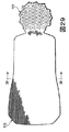
履物100では、ベロ124は、ニット構成要素130と分かれており、場合により縫製、接着または熱接合によってニット構成要素130に接合されている。さらに、ベロ124は、編みプロセスの後に、ニット構成要素130に付加されるように説明される。しかし、図25および図26に図示されているように、ニット構成要素130は、ニット要素131を用いた一体ニット構造で形成されているニットベロ170を含んでいる。すなわち、ニット要素131とベロ170は、編みプロセスによってワンピース要素として形成され、そのことは、以下でより詳細に説明する。ベロ124または別のベロは、ニット構成要素130が形成された後にニット要素131に接合してもよいが、ベロ170または別のニットベロは、編みプロセス中に、ニット構成要素130の一部を有する一体ニット構造で形成してもよい。
<Knit component with tongue>
In the
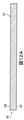
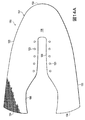
ベロ170は、ニット構成要素130から成るスロート区域(すなわち、締めひも122および締めひも開口123が配置されている箇所)内に配置され、そのスロート区域に沿って延びている。ベロ170は、例えば、履物100に組み込んだ場合、そのスロート区域の前方部から足首開口部121まで延びている。ニット要素131と同様に、ベロ170は、あまりテクスチャード加工されていない布地と、共通のまたは単一のニット構造とで形成されているように図示されている。また、ベロ170は、大略的に平坦な構造を有するように図27に図示されている。この構造をベロ170に与えることのできるニット構造およびニット要素131の実施例は、上述したニットゾーン160〜162におけるさまざまなニット構造のうちのいずれかである。しかし、さらなる構成では、メッシュニットゾーン163〜165から成るニット構造を用いることによって、ベロ170の区域に開口を形成してもよく、モックメッシュニットゾーン166または167から成るニット構造を用いることによって、ベロ170の区域に凹みを形成してもよく、または、ハイブリッドニットゾーン168から成るニット構造を用いることによって、ベロ170の区域に、開口および凹みから成る組合せを形成してもよい。さらに、ベロ170の区域は、例えば、パッド入りゾーン169と同様の層およびフローティングヤーンを有するように形成した場合、パッド入りの態様を有してもよい。したがって、ベロ170のテクスチャード加工されていない平らな態様を実施例のために図示し、異なるニット構造の利用によって、さまざまな特徴を与えてもよい。
The
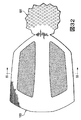
図28および図29を参照すると、ニット構成要素150のニット要素151内に、一体ニット構造で形成されているニットベロ175が図示されている。ベロ175は、ベロ170と同じ一般的形状を有しているが、より大きな厚みを有するパッド入り態様を有してもよい。より具体的には、ベロ175は、一体ニット構造で形成することができる2つの重なり合う、少なくとも部分的に同一の広がりを有するニット層176と、層176間に配置された複数のヤーンループ177とを含むように図30に図示されている。層176の側部または縁部は、互いに固定または編まれているが、中央区域は、大略的に固定されていない。したがって、層176は、チューブまたは管状構造を有効に形成し、ヤーンループ177は、層176間に配置され、および層176のうちの1つから外側へ延びている。実際には、ヤーンループ177は、層176間の内部空間を満たして、圧縮性またはパッド入りの態様をベロ175に与えている。また、層176およびヤーンループ177の各々は、ニット構成要素150を形成する編みプロセス中に、一体ニット構造で形成してもよい。
Referring to FIGS. 28 and 29, a
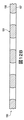
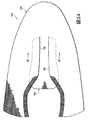
別のニット構成要素180は、ニット要素181と、インレイストランド182と、ニットベロ183とを含むように図31に図示されている。ベロ183の存在を除いて、ニット構成要素180は、参照によって本願明細書に組み込まれる、Duaによる米国特許出願公開第2010/0154256号明細書に開示されているニット構成要素から成る一般的な構造を有している。ベロ183は、ニット要素181とともに一体ニット構造で形成され、さまざまなニット構造を含んでいる。図32を参照すると、例えば、ベロ183の周辺区域は、ニットゾーン160〜162にさまざまなニット構造のうちのいずれかを有していてもよい、テクスチャード加工されていない構成を呈している。ベロ183の少なくとも2つの区域は、開口を組み込んでおり、およびメッシュニットゾーン163〜165に、さまざまなニット構造のうちのいずれかを有してもよい。図33を参照すると、ベロ183の中央区域は、一体ニット構造で形成することができる2つの重なり合う、少なくとも部分的に同一の広がりを有するニット層184と、層184間に延びている複数のフローティングヤーン185とを含む圧縮性またはパッド入りの態様を有している。そのため、ベロ183の中央区域は、パッド入りゾーン169から成るニット構造を呈していてもよい。層184の側部または縁部は、互いに固定されているが、中央区域は、大略的に固定されていなくてもよい。したがって、層184は、チューブまたは管状構造を有効に形成し、その管状構造の中を通るように、フローティングヤーン185を層184間に配置または挿入することができる。すなわち、フローティングヤーン185は、層184間に延びており、層184の表面に大略的に平行であり、層184間の内部空間を通って満たしている。ベロ183の大部分は、互いにかみ合うループを形成するように機械的に操作されるヤーンから形成されているが、フローティングヤーン185は、大略的に束縛されていないか、または、他の方法で層184間の内部空間に挿入されている。追加的な問題として、層184は、ニット層140およびフローティングヤーン141の場合に述べた利点を与えるために、ストレッチヤーンから少なくとも部分的に形成してもよい。
Another
ベロ183は、さまざまなニット構造を用いることができる方法の実施例を示している。上述したように、ベロ183の周辺区域は、テクスチャード加工されていない構成を呈し、ベロ183の2つの区域は開口を組み込んでおり、ベロ183の中央区域は、ニット層184とフローティングヤーン185を含んでいて、圧縮性またはパッド入りの態様を実現している。また、モックメッシュニット構造およびハイブリッドニット構造を用いてもよい。したがって、さまざまなニット構造をベロ183または他の何らかのニットベロ(例えば、ベロ170および175)に組み込んで、異なる特性または美観を与えることができる。
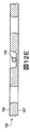
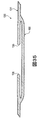
ベロ170は、ニット要素131のスロート区域の前方部に固定されている。すなわち、ベロ170は、履物100の足先領域101に最も近いスロート区域の一部において、縫製によってニット要素131に接合される。ベロ175および183の各々は、それぞれ、ニット構成要素150および180の同じ位置に固定されるか、または編みこまれる。しかし、図34および図35を参照すると、ニットベロ190は、インレイストランド132または締めひも開口123を含んでいないニット構成要素131から成る構成のスロート区域の長さに沿って固定されている。より具体的には、ベロ190の縁部は、内縁部135から外側に離間しているニット要素131の区域に編み込まれている。したがって、ベロ170,175,183および190から成る構成はどれでも、ニット構成要素130,150および180のスロート区域内のさまざまな位置に(例えば、一体ニット構造によって)固定することができる。
The
編みプロセス中にベロ170を作るという利点および一体ニット構造から成るベロ170を作るという利点は、より効率的な製造特性であり、共通の特性である。より具体的には、製造効率は、より一層のニット構成要素130を編みプロセス中に形成して、多くの場合、人の手で実行されるさまざまな工程(例えば、独立したベロを形成する工程、そのベロを固定する工程)をなくすことによって向上させることができる。ベロ170とニット要素131は、同じヤーン(または、同じ種類のヤーン)から、または同様のニット構造で形成した場合、共通の特性を有してもよい。例えば、ベロ170およびニット要素131の両方に同じヤーンを用いることにより、同様の耐久性、強度、伸縮性、耐摩耗性、生物分解性、熱特性および疎水性が与えられる。物理的特性に加えて、ベロ170とニット要素131の両方に同じヤーンを用いることにより、色、光沢および質感等の共通の美観または触覚特性を与えてもよい。また、ベロ170とニット要素131の両方に同じニット構造を用いることにより、共通の物理特性および美観性を与えてもよい。これらの利点は、ニット要素131の少なくとも一部と、ベロ170の少なくとも一部とが、共通のヤーン(または、共通の種類のヤーン)から、または、共通のニット構造で形成される場合に有ってもよい。
The advantage of making the
ベロ175は、層176間にヤーンループ177を含み、ベロ183は、層184間にフローティングヤーン185を含んでいる。ヤーンループ177およびフローティングヤーン185の利点は、圧縮性またはパッド入りの区域が形成されるということである。ヤーンループ177およびフローティングヤーン185に加えて、他の種類のフリーヤーン部分を用いてもよい。本出願の目的のために、「フリーヤーン部分」またはその変形は、例えば、フローティングヤーン、インレイヤーン、テリーループ、ヤーンの端部、およびヤーンのカット部分等の、ニット構造の(例えば、コースおよびウェールを画定する)互いにかみ合うループを直接的に形成していないヤーンのセグメントまたは部分として定義される。さらに、フリーヤーン部分は、個々のヤーンの1つの部分であってもよく、そのヤーンの他の部分は、ニット構造の互いにかみ合っているループを形成していることに留意すべきである。例えば、テリーループを形成するヤーンの部分(例えば、フリーヤーン部分)は、ニット構造の互いにかみ合うループを形成するヤーンの部分の間にあってもよい。あるいは、フリーヤーン部分に対する代替例として、発泡材料または他の種類の圧縮性材料を、ベロ175および183のいずれかに用いてもよい。
最終的な事項として、ベロ170がニット構成要素130とともに開示されているが、ベロ170は、ニット構成要素150および180および他のニット構成要素とともに用いてもよい。同様に、ベロ175,183および190は、ニット構成要素130,150および180および他のニット構成要素のうちのいずれかとともに用いてもよい。そのため、本願明細書において開示されている組合せは、実施例のためのものであり、その他の組合せを用いてもよい。さらに、ベロ170,175,183および190の特定の構成も、実施例を示すことを意図しており、大幅に変更してもよい。例えば、層184およびフローティングヤーン185の位置は、拡大してもよく、ベロ183の周辺まで移動させてもよく、または、ベロ183から取り除いてもよい。したがって、さまざまな組合せ構成が、実施例を示すために意図され、他の組合せや構成を用いてもよい。
As a final matter, the
〈ベロ編みプロセス〉
次に、編み機200が、ニット構成要素をベロとともに製造するために作動する方法を詳細に説明する。さらに、以下の説明は、ニット要素131とベロ170が一体ニット構造で形成される方法を論証しているが、他のニット構成要素およびベロのために、同様のプロセスを用いてもよい。図36A〜図36Gを参照すると、編み機200の一部が、針床201と、1つのレール203と、1つの標準フィーダー204と、1つのコンビネーションフィーダー220とを含むように模式的に図示されている。ニット構成要素130は、針床201の間で形成されるが、ニット構成要素130は、(a)編みプロセスの説明時に、より見やすいように、(b)互いに対するニット構成要素130の部分の位置と針床201とを示すように、針床201に隣接して図示されていることを理解すべきである。また、1つのレール203と、1つの標準フィーダー204と、1つのコンビネーションフィーダー220が図示されているが、追加的なレール203、標準フィーダー204およびコンビネーションフィーダー220を用いてもよい。したがって、編み機200の大略的な構造は、編みプロセスを説明するために簡略化されている。
<Bello knitting process>
Next, the method by which the
まず、図36Aに図示されているように、ベロ170の一部が編み機200によって形成される。ベロ170のこの部分を形成する際、標準フィーダー204は、レール203に沿って繰り返し移動し、さまざまなコースが、少なくともヤーン211から形成される。より具体的には、針202は、前のコースのループを通ってヤーン211の区画を引き、それによって、別のコースを形成する。この動作は、図36Bに図示されているように、ベロ170が実質的に形成されるまで続く。この段階では、ベロ170は、1つのヤーン211から形成されているように図示されているが、追加的なヤーンを、さらなる標準フィーダー204からベロ170に組み込んでもよいことに留意すべきである。例えば、ベロ170がニット要素131に確実に正しく接合または編み込まれるのを補助するために、融着性ヤーンを、少なくともベロ170の上方または最終コースに組み込んでもよい。加えて、少なくともベロ170の最終コースは、編みプロセスの後の段階中に、ベロ170が針202上に確実に正確に配置されたままになるように、比較的堅くまたは密に編んだクロスタック編みを含んでもよい。
First, as shown in FIG. 36A, a part of the
ここで、編み機200は、前述した編みプロセスに従って、図36Cに図示されているように、ニット要素131の形成プロセスを始める。編みプロセスが続くにつれて、コンビネーションフィーダー220は、前述した編みプロセスにも従って、図36Dに図示されているようにヤーン206をはめ込み、インレイストランド132を形成する。図36Cと図36Dの比較により、ベロ170は、針床201に対して静止したままであるが、ニット要素131は下方に移動し、連続的なコースがニット要素131に形成されるにつれて、ベロ170に重なる可能性がある。このことは、ベロ170をニット要素131に接合することが意図されているコースが形成されるまで続く。より具体的には、ベロ170は、ニット構成要素131から成る部分が形成される際、針床201に対して静止したままである。しかし、図36Eに図示されている時点では、(a)クロスタック編みを含む、ベロ170の最終コースにわたり、(b)ベロ170の最終コースに接合するコースが形成される。実際には、このコースは、ベロ170をニット要素131に接合する。したがって、この段階では、ニット要素131とベロ170は、一体ニット構造で有効に形成されている。
Here, the
ベロ170が一度ニット要素131に接合されると、編み機200は、コースを形成するというプロセスを続け、それによって、図36Fに図示されているように、ニット要素131のより多くを形成する。ここで、ベロ170がニット要素131に接合されているのであれば、ベロ170は、図36Eと図36Fの比較によって分かるように、連続的なコースが形成されるにつれて、ニット要素131とともに下方へ移動する。前方へ移動して、編み機200は、図36Gに図示されているように、ニット構成要素130が実質的に形成されるまで、ニット要素131にコースを形成するというプロセスを続ける。
Once the
ベロ170を含むようにニット構成要素130を形成することに関連する一般的なプロセスが存在するため、編みプロセスの追加的な態様について説明する。上述したように、ベロ170が確実および正確にニット要素131に接合または編み込まれるのを補助するために、融着性ヤーンを少なくともベロ170の最終コースに組み込んでもよい。いくつかの編みプロセスにおいて、ベロ170の最終コースを形成するヤーンはカットされる。融着性ヤーンをベロ170の最終コースに組み込むことにより、ベロ170とニット要素131との境界におけるニット構造を強化してもよい。すなわち、その融着性ヤーンの溶融は、その境界において、ヤーンの区画を溶かし、またはその区画に接合し、カットしたヤーンの解れを防止するであろう。
Because there is a general process associated with forming the
また、上述したように、少なくともベロ170の最終コースは、編みプロセスの後の段階中に、ベロ170が確実に針202上に正しく配置されたままになるように、比較的堅く、または密に編んだクロスタック編みを含んでもよい。ニット要素131を形成する編みプロセスのほとんどの間、ベロ170は、針床201に対して静止したままである。しかし、編み機200の動き、振動または他の動作は、針202から最終コースの部分を除去し、それによって目落ちを形成する可能性がある。比較的堅く、または密に編んだクロスタック編みを形成することにより、目落ちはあまり形成されない。さらに、目落ちが形成された場合、最終コース内の融着性ヤーンは、溶解するか、または、ニット構造内の目落ちを接合するであろう。
Also, as noted above, at least the final course of
ベロ170が一度編まれると、ニット要素131が形成される間、さまざまな針202が、ベロ170を定位置に保持する。実際には、ベロ170を保持する針202は、ベロ170がニット要素131に接合されるまで、さらなる編みには利用できない。その結果として、ベロ170の縁部を越えて(すなわち、ベロの右および左に)配置されたそれらの針202のみが、ニット要素131を形成するのに利用できる。したがって、ベロ170の最終コースは、ベロ170がニット要素131に接合される区域内の内縁部135の両側部間の距離以下の幅を有していなければならない。換言すれば、ニット構成要素130のデザインは、(a)ベロ170の最終コースの長さと、(b)ニット要素131が形成されている間、ベロ170を保持するために用意しておく針202の数を考慮しなければならない。
Once the
上述した編みプロセスでは、ベロ170およびニット要素131はともに、ヤーン211から形成される。ベロ170は、編みプロセスの一部の間、針床201に対して静止したままであるが、ニット要素131から成る部分は、連続的なコースが形成されるにつれて、下方へ移動する。ヤーン211のセグメントが、ベロ170の最終コースから、ニット要素131の最初のコース(すなわち、ニット要素131の底縁部)まで延びている可能性があることを考えれば、このヤーンのセグメントは、ニット要素131の最初のコースの下方への動きを考慮するための十分な長さを有していなければならない。実際には、図36C〜図36Eの比較によって、ニット要素131が形成されるにつれて、ニット要素131の最初のコースが下方へ移動して、ベロ170の最終コースから離れていくことが実証されている。したがって、ヤーン211のセグメントが、ベロ170の最終コースから、ニット要素131の最初のコースまで延びる場合、このヤーンのセグメントは、ベロ170の最終コースと、ニット要素131の最初のコースとの間の増大する距離を考慮するための十分な長さを有していなければならない。
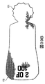
In the knitting process described above, the
さまざまな方法を、ベロ170の最終コースと、ニット要素131の最初のコースとの間の増大する距離を考慮するのに利用してもよいが、図37は、ベロ170の形成後に続いて形成される伸張区画195を図示している。この場合、伸張区画195は、針202の編み目を閉じてもよい。ベロ170の最終コースと、ニット要素131の最初のコースとの間の距離が増加する際に、伸張区画195が解けて延びる可能性がある。すなわち、伸張区画195の解きは、ベロ170の最終コースと、ニット要素131の最初のコースとの間で、ヤーン211の区画を有効に延ばすのに用いることができる。いくつかの構成では、伸張区画195は、解きを容易にするためのジャージ生地として形成してもよい。
Various methods may be utilized to take into account the increasing distance between the final course of the
さまざまな図36A〜図36Gが、独立して形成されるニット構成要素130を示している。しかし、いくつかの編みプロセスでは、ニット構成要素130を形成する前に、屑要素が編み込まれる。屑要素は、下方への力をニット構成要素130に与える、さまざまなローラーに絡む。その下方への力は、後のコースが形成されるにつれて、コースが針202から離れていくことを確実にする。
Various FIGS. 36A-36G illustrate knit
上記の説明に基づいて、ニット要素131とベロ170は、単一の編みプロセスによって、一体ニット構造で形成してもよい。上述したように、まずベロ170が形成されて、ニット要素131が形成される際、そのベロ170は、針床201上で静止したままである。ニット要素131とベロ170を接合するコースが形成された後、ニット要素131およびベロ170は、ニット要素131のさらなる部分が形成されるにつれて、一緒に下方へ移動する。
Based on the above description, the
〈連続的変化〉
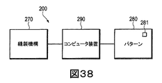
図38に模式的に図示されているように、編み機200は、いくつかある構成要素の中で、縫製機構270と、パターン280と、コンピュータ装置290とを含んでいる。縫製機構270は、ニット構成要素(例えば、ニット構成要素130)を形成するために、ヤーン206および211を機械的に操作する編み機200の機械的コンポーネントの多く(例えば、針202、フィーダー204および220、キャリッジ205)を含んでいる。パターン280は、例えば、各ひと縫いに用いられるヤーンと、各ひと縫いによって形成されるニット構成要素の種類と、各ひと縫いに用いられる特定の針202とフィーダー204および220とを含む、ニット構成要素に関するデータを含んでいる。編み機200の動作は、コンピュータ装置290によって制御され、そのコンピュータ装置は、パターン280からデータを読み出して、縫製機構270の対応する動作を指示する。
<Continuous change>
As schematically illustrated in FIG. 38, the
多様な、および実質的に同一のニット構成要素を、編み機200によって形成してもよい。より具体的には、コンピュータ装置290は、パターン280を繰り返し読み出して、実質的に同一のニット構成要素を形成するように縫製機構270に指示する。したがって、一般的に、形成される各ニット構成要素は、特定のパターン280に基づいて形成される他のニット構成要素と実質的に同一になる。しかし、図39A〜図39Cを参照すると、3つのバージョンのベロ170が図示されている。図39Aは、「1 OF 100」を形成する英数字を有するニット構造(例えば、異なる色を有するヤーン)を含むベロ170を図示しているが、図39Bと図39Cは、それぞれ、「2 OF 100」および「3 OF 100」を形成する英数字を有するニット構造を含むベロ170を図示している。
Various and substantially identical knitted components may be formed by the
図39A〜図39Cに示す種類の連続的変化を実現する1つの方法は、多数のパターンを生成することである。実際には、図39A〜図39Cに示すベロ170の構成の各々は、異なるパターンを有してもよい。あるいは、各連続するベロ170が、連続的変化をもたらすように形成されている間、コンピュータ装置290によって作動するアプリケーション(例えば、ソフトウェア)が、パターン280を変更してもよい。例えば、パターン280は、コンピュータ装置290によってアップデートまたは変えることのできるパターン280の領域である変更可能なフィールド281を含んでもよい。参考のために、図39A〜図39Cにおいて「1」、「2」および「3」に一致するパターン280の部分は、変更可能なフィールド281によって制御することができる。コンピュータ装置290は、例えば、形成される各連続するニット構成要素に伴って変更可能なフィールド281をアップデートするカウンタを含んでもよい。したがって、パターン280の連続的変化は、コンピュータ装置290によって作動するアプリケーションの利用によって自動化することができ、それにより、ベロ170の各連続的変化のための異なるパターン280の必要性をなくすことができる。
One way to achieve the type of continuous change shown in FIGS. 39A-39C is to generate multiple patterns. In practice, each of the configurations of the
動作時に、変更可能なフィールド281を有するパターン280は、例えば、オペレータ、デザイナーまたは製造者によって与えられる。コンピュータ装置290は、変更可能なフィールド281のための初期設定によって第1のニット構成要素を形成するか、または、他の命令またはデータに従って変更可能なフィールド281をアップデートしてもよい。したがって、例えば、図39Aのベロ170は、「1 OF 100」で編むことができる。ここで、コンピュータ装置290は、別の英数字を表すデータで、すなわち、コンピュータ装置290がカウンタを含んでいる場合は、可能な限り連続する英数字を表すデータによって、変更可能なフィールド281をアップデートし、その後、図39Bのベロ170を、「2 OF 100」で編むことができる。その処理手順が繰り返され、コンピュータ装置290が、別の英数字を表すデータで、変更可能なフィールド281をアップデートし、その後、図39Cのベロ170を「3 OF 100」で編むことができる。したがって、パターン280の変更可能なフィールドは、異なる英数字、できれば連続する英数字を表すデータで、繰り返しアップデートすることができる。
In operation, a
本発明を、さまざまな構成を参照して、上記および添付図面に開示している。しかし、その開示が果たす目的は、本発明に関連するさまざまな特徴および概念の実施例を提供することであり、本発明の範囲を限定することではない。当業者は、添付クレームによって定義される本発明の範囲から逸脱することなく、上述した構成に対して、さまざまな変形および変更を実行してもよいことを正しく認識するであろう。 The present invention is disclosed above and in the accompanying drawings with reference to various configurations. The purpose served by the disclosure, however, is to provide examples of the various features and concepts related to the invention and not to limit the scope of the invention. Those skilled in the art will appreciate that various modifications and changes may be made to the above-described configurations without departing from the scope of the invention as defined by the appended claims.
この明細書および添付図面からは、特許請求の範囲に記載した特徴以外にも、たとえば、以下のような特徴が抽出され得る。 In addition to the features described in the claims, for example, the following features can be extracted from this specification and the accompanying drawings.
A1.履物製品用のニット構成要素を製造する方法であって、編み機でベロを編むことと、前記ベロが前記編み機の針床に対して静止されるように、前記編み機の針に前記ベロを保持することと、前記ベロが前記針に保持されている間に、前記編み機で、前記ベロと重なるようにニット要素の第1の部分を編むことと、前記ベロを、前記ニット要素の前記第1の部分に接合することと、前記編み機で、前記ニット要素の第2の部分を編むことと、を含む方法。 A1. A method of manufacturing a knitted component for an article of footwear comprising knitting a tongue with a knitting machine and holding the tongue on a needle of the knitting machine such that the tongue is stationary relative to the needle bed of the knitting machine Knitting a first portion of the knit element with the knitting machine so as to overlap the tongue while the tongue is held by the needle; and Joining the portions and knitting a second portion of the knit element with the knitting machine.
A2.前記編み機を横編機になるように選択するステップをさらに含む、A1に記載の方法。 A2. The method of A1, further comprising selecting the knitting machine to be a flat knitting machine.
A3.前記ベロを編むステップの後に続いて、伸張区画を編むステップをさらに含み、前記ニット要素の前記第1の部分を編むステップは、前記伸張区画を解くことを含む、A1またはA2に記載の方法。 A3. A method according to A1 or A2, further comprising the step of knitting a stretch section following the step of knitting the tongue, wherein the step of knitting the first portion of the knit element comprises unwinding the stretch section.
A4.前記ベロを編むステップは、(a)融着性ヤーンおよび(b)クロスタック編みのうちの少なくとも一方を含むように、前記ベロのコースを形成することを含む、A1〜A3のいずれかに記載の方法。 A4. The step of knitting the belo includes forming a course of the belo so as to include at least one of (a) a fusible yarn and (b) a crosted knitting. the method of.
A5.前記ベロを接合するステップは、前記ベロを前記ニット要素に接合するコースを前記編み機で形成することを含む、A1〜A4のいずれかに記載の方法。 A5. The method according to any one of A1 to A4, wherein the step of joining the tongue includes forming a course on the knitting machine to join the tongue to the knit element.
A6.履物製品用のニット構成要素を製造する方法であって、ベロを編み機で編むことと、ニット要素の第1の部分を前記編み機で編むことであって、前記ニット要素の前記第1の部分が編まれている間は、前記ベロが、前記編み機の針床に対して静止しており、前記ニット要素の前記第1の部分は、前記ニット要素の前記第1の部分が編まれている間は、前記ベロに対して移動していることと、前記ベロを前記ニット要素に接合するコースであって、クロスタック編みを含むコースを前記編み機で形成することと、前記ニット要素の第2の部分を前記編み機で編むことであって、前記ベロと、前記ニット要素の前記第1の部分とは、前記ニット要素の前記第2の部分を編んでいる間は、一緒に動くことと、を含む方法。 A6. A method of manufacturing a knitted component for an article of footwear, comprising knitting a tongue with a knitting machine and knitting a first part of the knit element with the knitting machine, wherein the first part of the knit element is While being knitted, the tongue is stationary with respect to the needle bed of the knitting machine, and the first portion of the knit element is while the first portion of the knit element is being knitted. Are moving relative to the tongue, forming a course for joining the tongue to the knit element, the course including cross-stitch knitting with the knitting machine, and a second of the knit element. Knitting a part with the knitting machine, wherein the tongue and the first part of the knit element move together while knitting the second part of the knit element; Including methods.
A7.前記編み機を横編機になるように選択するステップをさらに含む、A6に記載の方法。 A7. The method of A6, further comprising selecting the knitting machine to be a flat knitting machine.
A8.前記ベロを編むステップの後に続いて、伸張区画を編むステップをさらに含み、前記ニット要素の前記第1の部分を編むステップは、前記伸張区画を解くことを含む、A6またはA7に記載の方法。 A8. A method according to A6 or A7, further comprising the step of knitting a stretch section following the step of knitting the tongue, wherein the step of knitting the first portion of the knit element comprises unwinding the stretch section.
A9.前記ベロを編むステップは、(a)融着性ヤーンおよび(b)クロスタック編みのうちの少なくとも一方を含むように、前記ベロの最終コースを形成することを含む、A6〜A8のいずれかに記載の方法。 A9. The step of knitting the belo includes forming a final course of the belo so as to include at least one of (a) a fusible yarn and (b) a crochet knitting. The method described.
A10.編みパターンに変更可能なフィールドを与えることと、第1の英数字を表すデータで前記変更可能なフィールドをアップデートすることと、前記第1の英数字のニット構造を有する第1のニット構成要素を編むことと、第2の英数字を表すデータで前記変更可能なフィールドをアップデートすることであって、前記第2の英数字は、前記第1の英数字とは異なっていることと、前記第2の英数字のニット構造を有する第2のニット構成要素を編むことと、を含む、A1またはA6に記載の方法。 A10. Providing a changeable field to the knitting pattern; updating the changeable field with data representing a first alphanumeric character; and a first knit component having the first alphanumeric knit structure. Knitting and updating the changeable field with data representing a second alphanumeric character, wherein the second alphanumeric character is different from the first alphanumeric character; Knitting a second knitted component having a two alphanumeric knitted structure.
A11.前記第2の英数字は、前記第1の英数字から連続している、A10に記載の方法。 A11. The method of A10, wherein the second alphanumeric character is contiguous with the first alphanumeric character.
Claims (13)
前記アッパーの外面と、前記外面に対向し足を受け入れるための空洞を区画する前記アッパーの内面とのうちの少なくとも一方の一部を区画するニット要素と、
前記アッパーのスロート区域を通って延びているベロであって、当該ベロと前記ニット要素とがワンピースニット要素として形成されるように前記ニット要素によって形成されたベロとを含み、
前記ベロが外側縁および内側縁を有し、前記ベロの前記外側縁および前記内側縁が、前記アッパーの前記スロート区域の内側側部および外側側部に沿って前記ニット要素に固定されておらず、
前記ベロが、前記ワンピースニット要素を形成するために、少なくとも一つの共通のコースに沿って前記ニット要素と接合されるように、前記スロート区域の前方部分における前記ニット要素に固定されている、アッパー。 An upper for footwear products,
A knit element that defines a part of at least one of the outer surface of the upper and the inner surface of the upper that faces the outer surface and defines a cavity for receiving a foot;
A tongue extending through the throat section of the upper, the tongue being formed by the knit element such that the tongue and the knit element are formed as a one-piece knit element;
The tongue has an outer edge and an inner edge, and the outer edge and the inner edge of the tongue are not fixed to the knit element along the inner side and the outer side of the throat area of the upper ,
An upper secured to the knit element at a forward portion of the throat area such that the tongue is joined to the knit element along at least one common course to form the one-piece knit element; .
前記ベロの少なくとも一部が、前記第1ニット層、前記第2ニット層、および、複数のフリーヤーン部分を有し、前記第1ニット層および前記第2ニット層が、互いに隣接しており、前記ベロの前記内側縁および前記外側縁のそれぞれに沿って一緒に形成されており、前記フリーヤーン部分が前記第1ニット層と前記第2ニット層との間に配置されている、請求項1〜4のいずれか一項に記載のアッパー。 The tongue includes a first knit layer and a second knit layer;
At least a portion of the tongue has the first knitted layer, the second knitted layer, and a plurality of free yarn portions, wherein the first knitted layer and the second knitted layer are adjacent to each other; 2, formed together along each of the inner and outer edges of the tongue, wherein the free yarn portion is disposed between the first knitted layer and the second knitted layer. The upper as described in any one of -4.
前記ベロに関連する複数のコースが、前記ベロの前記内側縁および前記外側縁のそれぞれに沿って互いにのみ接合されている、請求項1〜11のいずれか一項に記載のアッパー。 At least one course associated with the knit element is joined to at least one course associated only with the tongue and along only the front portion of the throat area;
The upper according to any one of claims 1 to 11, wherein a plurality of courses associated with the tongue are joined only together along each of the inner and outer edges of the tongue.
前記ニット要素に関連するコースと前記ベロに関連するコースとが、前記アッパーの前記スロート区域前記内側側部と前記外側側部とに沿って固定されていない、請求項1〜12のいずれか一項に記載のアッパー。 The knit element has at least one course substantially continuous with at least one course of the belo at the front portion of the throat section of the upper;
The course associated with the knit element and the course associated with the tongue are not fixed along the throat area of the upper side and the outer side of the upper. The upper according to item.
Applications Claiming Priority (2)
| Application Number | Priority Date | Filing Date | Title |
|---|---|---|---|
| US13/400,511 US8448474B1 (en) | 2012-02-20 | 2012-02-20 | Article of footwear incorporating a knitted component with a tongue |
| US13/400,511 | 2012-02-20 |
Related Parent Applications (1)
| Application Number | Title | Priority Date | Filing Date |
|---|---|---|---|
| JP2014557864A Division JP6122878B2 (en) | 2012-02-20 | 2013-02-19 | Footwear products incorporating knit components with tongues |
Related Child Applications (1)
| Application Number | Title | Priority Date | Filing Date |
|---|---|---|---|
| JP2019041703A Division JP7005544B2 (en) | 2012-02-20 | 2019-03-07 | Manufacturing method of knit components |
Publications (2)
| Publication Number | Publication Date |
|---|---|
| JP2017124228A true JP2017124228A (en) | 2017-07-20 |
| JP6527545B2 JP6527545B2 (en) | 2019-06-05 |
Family
ID=48445228
Family Applications (6)
| Application Number | Title | Priority Date | Filing Date |
|---|---|---|---|
| JP2014557864A Active JP6122878B2 (en) | 2012-02-20 | 2013-02-19 | Footwear products incorporating knit components with tongues |
| JP2015560294A Active JP6443993B2 (en) | 2012-02-20 | 2014-02-27 | Method for knitting a knit component with an integral knit tongue |
| JP2017073958A Active JP6527545B2 (en) | 2012-02-20 | 2017-04-03 | Footwear uppers |
| JP2019041703A Active JP7005544B2 (en) | 2012-02-20 | 2019-03-07 | Manufacturing method of knit components |
| JP2022000425A Active JP7301177B2 (en) | 2012-02-20 | 2022-01-05 | Method for manufacturing knitted components |
| JP2023100988A Pending JP2023118770A (en) | 2012-02-20 | 2023-06-20 | Method for manufacturing knitted component |
Family Applications Before (2)
| Application Number | Title | Priority Date | Filing Date |
|---|---|---|---|
| JP2014557864A Active JP6122878B2 (en) | 2012-02-20 | 2013-02-19 | Footwear products incorporating knit components with tongues |
| JP2015560294A Active JP6443993B2 (en) | 2012-02-20 | 2014-02-27 | Method for knitting a knit component with an integral knit tongue |
Family Applications After (3)
| Application Number | Title | Priority Date | Filing Date |
|---|---|---|---|
| JP2019041703A Active JP7005544B2 (en) | 2012-02-20 | 2019-03-07 | Manufacturing method of knit components |
| JP2022000425A Active JP7301177B2 (en) | 2012-02-20 | 2022-01-05 | Method for manufacturing knitted components |
| JP2023100988A Pending JP2023118770A (en) | 2012-02-20 | 2023-06-20 | Method for manufacturing knitted component |
Country Status (11)
| Country | Link |
|---|---|
| US (11) | US8448474B1 (en) |
| EP (5) | EP2817442B1 (en) |
| JP (6) | JP6122878B2 (en) |
| KR (3) | KR101626512B1 (en) |
| CN (3) | CN104246040B (en) |
| AR (1) | AR094973A1 (en) |
| BR (2) | BR112014020456B1 (en) |
| DE (7) | DE202013012927U1 (en) |
| HK (2) | HK1200507A1 (en) |
| TW (5) | TWI644632B (en) |
| WO (2) | WO2013126313A2 (en) |
Families Citing this family (139)
| Publication number | Priority date | Publication date | Assignee | Title |
|---|---|---|---|---|
| US7107235B2 (en) | 2000-03-10 | 2006-09-12 | Lyden Robert M | Method of conducting business including making and selling a custom article of footwear |
| US7347011B2 (en) | 2004-03-03 | 2008-03-25 | Nike, Inc. | Article of footwear having a textile upper |
| US7774956B2 (en) | 2006-11-10 | 2010-08-17 | Nike, Inc. | Article of footwear having a flat knit upper construction or other upper construction |
| US9301569B2 (en) | 2010-06-22 | 2016-04-05 | Nike, Inc. | Article of footwear with color change portion and method of changing color |
| US9060570B2 (en) | 2011-03-15 | 2015-06-23 | Nike, Inc. | Method of manufacturing a knitted component |
| US8839532B2 (en) | 2011-03-15 | 2014-09-23 | Nike, Inc. | Article of footwear incorporating a knitted component |
| US10172422B2 (en) | 2011-03-15 | 2019-01-08 | Nike, Inc. | Knitted footwear component with an inlaid ankle strand |
| US10398196B2 (en) | 2011-03-15 | 2019-09-03 | Nike, Inc. | Knitted component with adjustable inlaid strand for an article of footwear |
| US9420845B2 (en) * | 2011-12-27 | 2016-08-23 | Cheng-Tung Hsiao | Shoe upper structure |
| US9510636B2 (en) | 2012-02-20 | 2016-12-06 | Nike, Inc. | Article of footwear incorporating a knitted component with an integral knit tongue |
| US8448474B1 (en) * | 2012-02-20 | 2013-05-28 | Nike, Inc. | Article of footwear incorporating a knitted component with a tongue |
| US11319651B2 (en) | 2012-02-20 | 2022-05-03 | Nike, Inc. | Article of footwear incorporating a knitted component with an integral knit tongue |
| US20130255103A1 (en) | 2012-04-03 | 2013-10-03 | Nike, Inc. | Apparel And Other Products Incorporating A Thermoplastic Polymer Material |
| US20140130373A1 (en) * | 2012-11-15 | 2014-05-15 | Nike, Inc. | Article Of Footwear Incorporating A Knitted Component |
| US10182617B2 (en) | 2012-11-20 | 2019-01-22 | Nike, Inc. | Footwear upper incorporating a knitted component with collar and throat portions |
| US9498023B2 (en) | 2012-11-20 | 2016-11-22 | Nike, Inc. | Footwear upper incorporating a knitted component with sock and tongue portions |
| FR3002551B1 (en) * | 2013-02-26 | 2015-08-14 | Anton Percy Spielmann | METHOD FOR KNITTING A FOOTWEAR MEMBER AND FOOTWEAR COMPONENT OBTAINED BY SUCH A METHOD. |
| DE102013207155B4 (en) | 2013-04-19 | 2020-04-23 | Adidas Ag | Shoe upper |
| DE102013207163B4 (en) | 2013-04-19 | 2022-09-22 | Adidas Ag | shoe upper |
| US11666113B2 (en) | 2013-04-19 | 2023-06-06 | Adidas Ag | Shoe with knitted outer sole |
| DE102013207156A1 (en) | 2013-04-19 | 2014-10-23 | Adidas Ag | Shoe, in particular a sports shoe |
| US9538803B2 (en) * | 2013-05-31 | 2017-01-10 | Nike, Inc. | Method of knitting a knitted component for an article of footwear |
| BR112015030561A2 (en) * | 2013-06-17 | 2017-07-25 | Shima Seiki Mfg | upper and method for producing a upper |
| US10863794B2 (en) | 2013-06-25 | 2020-12-15 | Nike, Inc. | Article of footwear having multiple braided structures |
| EP2978332B1 (en) | 2013-06-25 | 2018-12-05 | NIKE Innovate C.V. | Article of footwear with braided upper |
| US9682519B2 (en) * | 2013-07-26 | 2017-06-20 | Aurora Flight Sciences Corporation | Integral composite bushing system and method |
| US9491983B2 (en) * | 2013-08-19 | 2016-11-15 | Nike, Inc. | Article of footwear with adjustable sole |
| US10645990B2 (en) | 2013-08-19 | 2020-05-12 | Nike, Inc. | Article of footwear with adjustable sole |
| KR101824546B1 (en) * | 2013-08-23 | 2018-02-01 | 가부시키가이샤 시마세이키 세이사쿠쇼 | Shoe upper and shoe upper manufacturing method |
| US10092058B2 (en) * | 2013-09-05 | 2018-10-09 | Nike, Inc. | Method of forming an article of footwear incorporating a knitted upper with tensile strand |
| US8701232B1 (en) | 2013-09-05 | 2014-04-22 | Nike, Inc. | Method of forming an article of footwear incorporating a trimmed knitted upper |
| TWI633851B (en) * | 2013-09-13 | 2018-09-01 | 島精機製作所股份有限公司 | Instep covers and knitting method of instep covers |
| US20150075031A1 (en) * | 2013-09-13 | 2015-03-19 | Nike, Inc. | Article Of Footwear Incorporating A Knitted Component With Monofilament Areas |
| US9145629B2 (en) * | 2014-02-03 | 2015-09-29 | Nike, Inc. | Article of footwear including a monofilament knit element with a fusible strand |
| US9072335B1 (en) * | 2014-02-03 | 2015-07-07 | Nike, Inc. | Knitted component for an article of footwear including a full monofilament upper |
| US8973410B1 (en) | 2014-02-03 | 2015-03-10 | Nike, Inc. | Method of knitting a gusseted tongue for a knitted component |
| US8997529B1 (en) * | 2014-02-03 | 2015-04-07 | Nike, Inc. | Article of footwear including a monofilament knit element with peripheral knit portions |
| DE102014202432B4 (en) | 2014-02-11 | 2017-07-27 | Adidas Ag | Improved football boot |
| US9920461B2 (en) * | 2014-03-04 | 2018-03-20 | Knitmasters, Llc | Knitted shoe components and methods of making the same |
| US10383388B2 (en) | 2014-03-07 | 2019-08-20 | Nike, Inc. | Article of footware with upper incorporating knitted component providing variable compression |
| WO2015146444A1 (en) * | 2014-03-28 | 2015-10-01 | 株式会社島精機製作所 | Shoe upper and method for knitting shoe upper |
| US9861162B2 (en) | 2014-04-08 | 2018-01-09 | Nike, Inc. | Components for articles of footwear including lightweight, selectively supported textile components |
| US9872537B2 (en) * | 2014-04-08 | 2018-01-23 | Nike, Inc. | Components for articles of footwear including lightweight, selectively supported textile components |
| KR101437472B1 (en) * | 2014-04-15 | 2014-11-04 | 송수복 | Upper of footwear, manufacturing method thereof, and footwear using it |
| US10368606B2 (en) | 2014-04-15 | 2019-08-06 | Nike, Inc. | Resilient knitted component with wave features |
| CN103989290A (en) * | 2014-04-30 | 2014-08-20 | 福建省莆田市双驰科技有限公司 | Shoe |
| BR112016024812A2 (en) * | 2014-05-02 | 2017-08-15 | Shima Seiki Mfg | shoe upper and sewing method of shoe upper |
| US9907349B2 (en) * | 2014-05-30 | 2018-03-06 | Nike, Inc. | Article of footwear including knitting a knitted component of warp knit construction forming a seamless bootie |
| US9877536B2 (en) * | 2014-05-30 | 2018-01-30 | Nike, Inc. | Method of making an article of footwear including knitting a knitted component of warp knit construction forming a seamless bootie with wrap-around portion |
| US9510637B2 (en) * | 2014-06-16 | 2016-12-06 | Nike, Inc. | Article incorporating a knitted component with zonal stretch limiter |
| US9661892B2 (en) * | 2014-07-29 | 2017-05-30 | Nike, Inc. | Article of footwear incorporating an upper with a shifted knit structure |
| US20160058099A1 (en) * | 2014-08-29 | 2016-03-03 | Nike, Inc. | Article of Footwear Incorporating a Knitted Component with Monofilament Areas in Body and Heel Portions |
| US9192204B1 (en) * | 2014-09-30 | 2015-11-24 | Nike, Inc. | Article of footwear upper incorporating a textile component with tensile elements |
| CN204763685U (en) * | 2014-09-30 | 2015-11-18 | 耐克创新有限合伙公司 | Shoes article with be arranged in combining part of weaving to article |
| US10822728B2 (en) | 2014-09-30 | 2020-11-03 | Nike, Inc. | Knitted components exhibiting color shifting effects |
| US9375046B2 (en) | 2014-09-30 | 2016-06-28 | Nike, Inc. | Article of footwear incorporating a knitted component with inlaid tensile elements and method of assembly |
| US9078488B1 (en) | 2014-09-30 | 2015-07-14 | Nike, Inc. | Article of footwear incorporating a lenticular knit structure |
| DE102014220087B4 (en) | 2014-10-02 | 2016-05-12 | Adidas Ag | Flat knitted shoe top for sports shoes |
| US9668544B2 (en) | 2014-12-10 | 2017-06-06 | Nike, Inc. | Last system for articles with braided components |
| US10674791B2 (en) * | 2014-12-10 | 2020-06-09 | Nike, Inc. | Braided article with internal midsole structure |
| JP6764409B2 (en) * | 2015-01-16 | 2020-09-30 | ナイキ イノベイト シーブイ | Footwear products |
| WO2016123316A2 (en) * | 2015-01-30 | 2016-08-04 | Nike Innovate C.V. | Method for forming a seamless knitted abutment |
| US10182656B2 (en) | 2015-04-13 | 2019-01-22 | Steelcase Inc. | Seating components with laminated bonding material |
| US10130142B2 (en) * | 2015-04-14 | 2018-11-20 | Nike, Inc. | Article of footwear with knitted component having biased inter-toe member |
| WO2016168046A2 (en) * | 2015-04-16 | 2016-10-20 | Nike Innovate C.V. | Article of footwear incorporating a knitted component having floated portions |
| EP3294084A4 (en) | 2015-05-08 | 2019-01-16 | Under Armour, Inc. | Footwear including a textile upper |
| TWI667968B (en) * | 2015-05-15 | 2019-08-11 | 荷蘭商耐克創新有限合夥公司 | Knitted component |
| US20160345675A1 (en) | 2015-05-26 | 2016-12-01 | Nike, Inc. | Hybrid Braided Article |
| US10555581B2 (en) | 2015-05-26 | 2020-02-11 | Nike, Inc. | Braided upper with multiple materials |
| US11000095B2 (en) | 2015-06-17 | 2021-05-11 | Nike, Inc. | Knitted member for an article of footwear |
| WO2017018158A1 (en) * | 2015-07-30 | 2017-02-02 | 株式会社島精機製作所 | Knitted fabric and method for joining knitted fabric |
| US11103028B2 (en) | 2015-08-07 | 2021-08-31 | Nike, Inc. | Multi-layered braided article and method of making |
| US9888742B2 (en) | 2015-09-11 | 2018-02-13 | Nike, Inc. | Article of footwear with knitted component having plurality of graduated projections |
| CN112890350B (en) * | 2016-01-15 | 2023-02-17 | 耐克创新有限合伙公司 | Method of manufacturing a footwear upper with a knitted component |
| TWI615105B (en) * | 2016-03-07 | 2018-02-21 | 重慶股份有限公司 | Method and system for manufacturing a footwear upper |
| EP4026936A1 (en) * | 2016-04-01 | 2022-07-13 | NIKE Innovate C.V. | Shoe upper having a knitted component with a strap |
| CN109068785B (en) * | 2016-04-25 | 2021-04-13 | 株式会社岛精机制作所 | Method for manufacturing shoe and shoe |
| US20170311681A1 (en) * | 2016-04-29 | 2017-11-02 | Aknit International Ltd. | Shoe body-forming piece and manufacturing method thereof |
| MX2019000272A (en) * | 2016-06-27 | 2019-09-09 | Nike Innovate Cv | A textile including bulking yarn. |
| US11445779B2 (en) * | 2016-07-21 | 2022-09-20 | Nike, Inc. | Article of footwear with multiple layers, retention system for an article of footwear, and methods of manufacture |
| CN109714998B (en) * | 2016-08-12 | 2021-11-02 | 耐克创新有限合伙公司 | Article having a first section with a first yarn and a second yarn |
| US10973268B2 (en) | 2016-08-25 | 2021-04-13 | Nike, Inc. | Garment with zoned insulation and variable air permeability |
| US11166516B2 (en) * | 2016-08-26 | 2021-11-09 | Nike, Inc. | Article of footwear having an upper that includes a knitted component with a cushioning region and methods for fabricating the same |
| US10349702B2 (en) * | 2016-09-09 | 2019-07-16 | Nike, Inc. | Knitting of multiple uppers on a machine |
| US10844526B2 (en) | 2016-10-23 | 2020-11-24 | Nike, Inc. | Upper including a knitted component having structures with apertures extending from a surface |
| GB2571231B (en) | 2016-11-09 | 2020-03-25 | Nike Innovate Cv | Textiles and articles, and processes for making the same |
| US10753019B2 (en) * | 2016-11-14 | 2020-08-25 | Nike, Inc. | Upper including a knitted component and a tab element |
| CN108342819B (en) * | 2017-01-25 | 2020-06-05 | 上海织遇织品有限公司 | Knitted boot and manufacturing method thereof |
| US11224261B2 (en) | 2017-02-10 | 2022-01-18 | Nike, Inc. | Knitted article with at least one scallop element and methods of manufacture |
| TWI632265B (en) * | 2017-03-10 | 2018-08-11 | 薩摩亞商紘織國際有限公司 | Method for integrally weaving an extended shoe with a flat knitting machine |
| TWI667965B (en) | 2017-03-10 | 2019-08-11 | 薩摩亞商紘織國際有限公司 | Method for manufacturing |
| EP3581056B1 (en) * | 2017-03-20 | 2021-09-15 | ASICS Corporation | Shoe upper |
| CN113729353B (en) * | 2017-04-21 | 2024-03-05 | 耐克创新有限合伙公司 | Sole structure with proprioceptive element and method of manufacturing sole structure |
| WO2018204652A1 (en) * | 2017-05-05 | 2018-11-08 | Nike Innovate C.V. | Upper for an article of footwear with first and second knitted portions and a method of making same |
| US11051573B2 (en) | 2017-05-31 | 2021-07-06 | Nike, Inc. | Braided articles and methods for their manufacture |
| US11202483B2 (en) | 2017-05-31 | 2021-12-21 | Nike, Inc. | Braided articles and methods for their manufacture |
| CN110891448B (en) * | 2017-05-31 | 2022-09-23 | 耐克创新有限合伙公司 | Knitted component for an article of footwear |
| US10806210B2 (en) | 2017-05-31 | 2020-10-20 | Nike, Inc. | Braided articles and methods for their manufacture |
| CN108978010B (en) * | 2017-06-05 | 2020-07-07 | 纮织国际有限公司 | Integrally formed three-dimensional shoe blank with tongue piece and manufacturing method thereof |
| TWI681728B (en) * | 2017-06-05 | 2020-01-11 | 薩摩亞商紘織國際有限公司 | Three-dimensional integrated shoe blank with tongue and method for manufacturing the same |
| CN107326517B (en) * | 2017-06-22 | 2019-01-01 | 宁波慈星股份有限公司 | A kind of weaving method of vamp |
| US10711380B2 (en) | 2017-07-13 | 2020-07-14 | Under Armour, Inc. | Article with embroidered tape segments |
| EP3662102B1 (en) * | 2017-08-04 | 2022-02-09 | NIKE Innovate C.V. | Article formed of a knitted component comprising at least one layered pod and knitted component |
| US10731279B2 (en) | 2018-01-20 | 2020-08-04 | Nike, Inc. | Knitted components reinforced with high tenacity yarn |
| US10791791B2 (en) * | 2018-01-20 | 2020-10-06 | Nike, Inc. | Articles of footwear reinforced with high tenacity yarn |
| US11168416B2 (en) | 2018-05-02 | 2021-11-09 | Fabdesigns, Inc. | System and method for knitting shoe uppers |
| US11828009B2 (en) | 2018-05-16 | 2023-11-28 | Fabdesigns, Inc. | System and method of unspooling a material into a textile machine |
| US11186930B2 (en) | 2018-05-17 | 2021-11-30 | Fabdesigns, Inc. | System and method for knitting shoe uppers |
| US11401638B2 (en) | 2018-05-22 | 2022-08-02 | Fabdesigns, Inc. | Method of knitting a warp structure on a flat knitting machine |
| USD888479S1 (en) | 2018-06-04 | 2020-06-30 | Steelcase Inc. | Chair arm |
| USD891842S1 (en) | 2018-06-04 | 2020-08-04 | Steelcase Inc. | Chair arm |
| US10736380B2 (en) | 2018-07-03 | 2020-08-11 | Under Armour, Inc. | Article with ribbon structure and embroidered edges |
| US10786043B2 (en) | 2018-07-03 | 2020-09-29 | Under Armour, Inc. | Article with thermally bonded ribbon structure and method of making |
| US10758007B2 (en) | 2018-07-03 | 2020-09-01 | Under Armour, Inc. | Article with thermally bonded ribbon structure and method of making |
| US10736381B2 (en) | 2018-07-03 | 2020-08-11 | Under Armour, Inc. | Article with directional tensioning |
| US10716362B2 (en) | 2018-07-03 | 2020-07-21 | Under Armour, Inc. | Article with ribbon structure having nodes and links |
| US10619280B2 (en) | 2018-07-03 | 2020-04-14 | Under Armour, Inc. | Method of making article with ribbon structure and embroidered edges |
| US10993497B2 (en) | 2018-11-15 | 2021-05-04 | Under Armour, Inc. | Article with ribbon loops for string lasting |
| WO2020123455A1 (en) * | 2018-12-10 | 2020-06-18 | Nike Innovate C.V. | Knitting method using needle bed racking and related knitted component for use as a shoe upper, and a knitting machine with extreme racking capability |
| CN111501184B (en) * | 2019-01-30 | 2021-10-26 | 佰龙机械厂股份有限公司 | Yarn feeder of flat knitting machine with variable yarn feeding position |
| US11421354B2 (en) * | 2019-02-27 | 2022-08-23 | Pai Lung Machinery Mill Co., Ltd. | Flat knitting machine yarn feeder with variable yarn feeding positions |
| KR102138621B1 (en) * | 2019-05-31 | 2020-07-28 | 아진시스텍(주) | Robot automation system for fastening of sandals upper and midsole using fiber rope |
| US11739448B2 (en) | 2019-05-31 | 2023-08-29 | Nike, Inc. | Knitted component with an inner layer having a thermoplastic material and related method |
| IT201900007821A1 (en) * | 2019-06-03 | 2020-12-03 | Lonati Spa | UPPER STRUCTURE AND PROCEDURE FOR THE PRODUCTION OF AN UPPER STRUCTURE. |
| US10806211B1 (en) | 2019-07-24 | 2020-10-20 | Biothread Llc | Footwear having therapeutic light source |
| CN114451628A (en) | 2019-08-02 | 2022-05-10 | 耐克创新有限合伙公司 | Outsole for an article of footwear |
| US11655570B2 (en) | 2019-10-08 | 2023-05-23 | Biothread Llc | Illuminated garment |
| IT201900019984A1 (en) * | 2019-10-29 | 2021-04-29 | Ffi Global S R L | ACCIDENT PREVENTION FOOTWEAR AND RELATED PRODUCTION METHOD |
| JP2021084322A (en) * | 2019-11-28 | 2021-06-03 | 株式会社リコー | Active energy ray-curable composition for inkjet, molding method, and molding apparatus |
| WO2021126480A1 (en) * | 2019-12-16 | 2021-06-24 | Ict Corporation | Knitted quilt fabric and compression garments made therefrom |
| US20210274887A1 (en) | 2020-03-09 | 2021-09-09 | Nike, Inc. | Upper for an article of footwear having angled tubular knit structures |
| US11399591B2 (en) | 2020-03-16 | 2022-08-02 | Robert Lyden | Article of footwear, method of making the same, and method of conducting retail and internet business |
| US20230073857A1 (en) | 2020-04-30 | 2023-03-09 | Safran Seats Usa Llc | Knit amenities panel for aircraft seat |
| US11576462B2 (en) * | 2020-06-29 | 2023-02-14 | Saucony, Inc. | Footwear with mesh sole construction |
| US20220110416A1 (en) * | 2020-10-09 | 2022-04-14 | Nike, Inc. | Upper for Article of Footwear |
| CN116670347A (en) * | 2020-12-31 | 2023-08-29 | 耐克创新有限合伙公司 | Knitted article with variable features |
| IL303989A (en) * | 2020-12-31 | 2023-08-01 | Nike Innovate Cv | Knit article with variable features |
| US20220205152A1 (en) | 2020-12-31 | 2022-06-30 | Nike, Inc. | Sleeve for an extremity |
| US20240081465A1 (en) * | 2022-09-14 | 2024-03-14 | Lululemon Athletica Canada Inc. | Upper for Article of Footwear Incorporating a Knitted Butterfly Workpiece |
Citations (6)
| Publication number | Priority date | Publication date | Assignee | Title |
|---|---|---|---|---|
| JPH08158208A (en) * | 1994-12-02 | 1996-06-18 | Shima Seiki Mfg Ltd | Knit fabric having cut-in pocket and method for knitting the same |
| US20050115284A1 (en) * | 2002-12-18 | 2005-06-02 | Nike, Inc. | Footwear with knit upper and method of manufacturing the footwear |
| JP2008291402A (en) * | 2007-05-25 | 2008-12-04 | Violetta Corp | Knitted fabric and method for producing the same |
| WO2010080182A1 (en) * | 2008-12-18 | 2010-07-15 | Nike International, Ltd. | Article of footwear having an upper incorporating a knitted component |
| WO2010098052A1 (en) * | 2009-02-25 | 2010-09-02 | 株式会社島精機製作所 | Tube-shaped knitted fabric, and knitting method therefor |
| WO2011043998A2 (en) * | 2009-10-07 | 2011-04-14 | Nike International, Ltd. | Article of footwear having an upper with knitted elements |
Family Cites Families (169)
| Publication number | Priority date | Publication date | Assignee | Title |
|---|---|---|---|---|
| US601192A (en) | 1898-03-22 | Tongue for boots or shoes | ||
| US1215198A (en) | 1916-09-21 | 1917-02-06 | Joseph Rothstein | Cushion instep-raiser. |
| US1597934A (en) | 1922-10-10 | 1926-08-31 | Edwin B Stimpson | Stocking |
| US1902780A (en) | 1930-04-11 | 1933-03-21 | Holden Knitting Co | Knitted lining for rubber footwear and method of making same |
| US1910251A (en) | 1931-12-09 | 1933-05-23 | Reliable Knitting Works | Knitted foot covering and method of making the same |
| US1888172A (en) | 1932-06-06 | 1932-11-15 | Reliable Knitting Works | Knitted footwear and method of making the same |
| US2001293A (en) | 1934-02-10 | 1935-05-14 | Wilson Wallace | Knitted stocking foot protector |
| US2047724A (en) | 1934-07-12 | 1936-07-14 | Louis G Zuckerman | Knitted article and method of making same |
| US2147197A (en) | 1936-11-25 | 1939-02-14 | Hood Rubber Co Inc | Article of footwear |
| US2330199A (en) | 1939-05-22 | 1943-09-28 | Basch Olive Holmes | Knitted article |
| GB538865A (en) | 1939-11-18 | 1941-08-20 | Harold Edmund Brew | Improvements relating to knitted fabrics and manufactured knitted articles |
| US2314098A (en) | 1941-04-26 | 1943-03-16 | Mary C Mcdonald | Method of making shoes |
| US2343390A (en) | 1941-11-26 | 1944-03-07 | United Shoe Machinery Corp | Method of stiffening shoes |
| US2400692A (en) | 1943-03-24 | 1946-05-21 | Theotiste N Herbert | Foot covering |
| US2440393A (en) | 1944-08-18 | 1948-04-27 | Frank W Clark | Process of making last-fitting fabric uppers |
| US2569764A (en) | 1946-07-25 | 1951-10-02 | Boyd Welsh Inc | Initially soft stiffenable material |
| US2608078A (en) | 1950-01-04 | 1952-08-26 | Munsingwear Inc | Foundation garment and element therefor |
| US2586045A (en) | 1950-06-23 | 1952-02-19 | Hoza John | Sock-type footwear |
| US2641004A (en) | 1950-12-26 | 1953-06-09 | David V Whiting | Method for producing knitted shoe uppers of shrinkable yarn |
| US2675631A (en) | 1951-02-13 | 1954-04-20 | Doughty John Carr | Footwear article of the slipper-sock type |
| DE870963C (en) | 1951-03-13 | 1953-03-19 | Georg Hofer | Strap for boots, especially for ski boots |
| DE1084173B (en) | 1954-09-18 | 1960-06-23 | Walter Geissler | Shoe upper |
| US2994322A (en) | 1959-01-12 | 1961-08-01 | Charles C Cullen | Protective supporter |
| GB1223285A (en) | 1967-08-29 | 1971-02-24 | Onitsuka Co | Improvements in shoes |
| DE6944404U (en) | 1969-11-14 | 1970-02-19 | Justus Rieker Co Dr | INNER SHOE FOR BOOTS, IN PARTICULAR SKI BOOTS MADE OF PLASTIC |
| US3704474A (en) | 1971-10-21 | 1972-12-05 | Compo Ind Inc | Method of string-lasting |
| US3766566A (en) | 1971-11-01 | 1973-10-23 | S Tadokoro | Hem forming construction of garments, particularly trousers and skirts |
| US3778856A (en) | 1971-11-05 | 1973-12-18 | Salient Eng Ltd | String lasting |
| DE2305693A1 (en) | 1972-02-07 | 1973-08-16 | Ici Ltd | NON-WOVEN STRUCTURE |
| NL7304678A (en) | 1973-04-04 | 1974-10-08 | Non woven stitched fabric - including thermoplastic fibres fused to increase mech resistance | |
| US4211806A (en) | 1973-09-19 | 1980-07-08 | Milliken Research Corporation | Treated fabric structure |
| US4031586A (en) | 1974-05-09 | 1977-06-28 | Von Den Benken Elisabeth | Insole for footwear |
| US3952427A (en) | 1974-05-09 | 1976-04-27 | Von Den Benken Elisabeth | Insole for footwear |
| IT1015280B (en) | 1974-06-21 | 1977-05-10 | Toja E | MACHINE FOR THE ASSEMBLY OF TO UPPER DIRECTLY ON THE ASSEMBLY SHAPES |
| US4027402A (en) | 1976-04-02 | 1977-06-07 | Liu Hsing Ching | Novel educational toy |
| US4232458A (en) | 1978-03-13 | 1980-11-11 | Wheelabrator Corp. Of Canada | Shoe |
| GB1603487A (en) | 1978-03-30 | 1981-11-25 | Inmont Corp | Leather like materials |
| CH620953A5 (en) | 1978-04-12 | 1980-12-31 | Dubied & Cie Sa E | |
| US4258480A (en) | 1978-08-04 | 1981-03-31 | Famolare, Inc. | Running shoe |
| US4255949A (en) | 1979-08-16 | 1981-03-17 | Thorneburg James L | Athletic socks with integrally knit arch cushion |
| US4317292A (en) | 1979-12-04 | 1982-03-02 | Florence Melton | Slipper sock and method of manufacture |
| US4373361A (en) | 1981-04-13 | 1983-02-15 | Thorneburg James L | Ski sock with integrally knit thickened fabric areas |
| IT8121560V0 (en) | 1981-04-23 | 1981-04-23 | Nuova Zarine Costruzione Macch | FOOTWEAR WITH UPPER ZONALLY COVERED BY SYNTHETIC MATERIAL INJECTED STABLY JOINED TO THE CANVAS. |
| US4465448A (en) | 1982-03-19 | 1984-08-14 | Norwich Shoe Co., Inc. | Apparatus for making shoes |
| US4499741A (en) * | 1982-05-19 | 1985-02-19 | Kemfast Textiles, Inc. | Stretchable knitted article with printed design |
| US5095720A (en) | 1982-07-14 | 1992-03-17 | Annedeen Hosiery Mill, Inc. | Circular weft knitting machine |
| JPS5964905U (en) * | 1982-10-20 | 1984-04-28 | 鷲尾 邦夫 | Pocket warmer sock cover and socks |
| JPS59162041A (en) | 1983-03-04 | 1984-09-12 | アキレス株式会社 | Manufacture of sheet-shaped article |
| JPS6325004U (en) | 1986-07-31 | 1988-02-18 | ||
| US4756098A (en) | 1987-01-21 | 1988-07-12 | Gencorp Inc. | Athletic shoe |
| US4737396A (en) | 1987-02-04 | 1988-04-12 | Crown Textile Company | Composite fusible interlining fabric |
| US4813158A (en) | 1987-02-06 | 1989-03-21 | Reebok International Ltd. | Athletic shoe with mesh reinforcement |
| US4750339A (en) | 1987-02-17 | 1988-06-14 | Golden Needles Knitting & Glove Co., Inc. | Edge binding for fabric articles |
| DE3705908A1 (en) | 1987-02-24 | 1988-09-01 | Arova Mammut Ag | PADDED BELT |
| US4843653A (en) | 1988-02-22 | 1989-07-04 | Coble Terry G | Moisture absorbent wristband |
| US5152025A (en) | 1988-07-29 | 1992-10-06 | Sergio Hirmas | Method for manufacturing open-heeled shoes |
| WO1990003744A1 (en) | 1988-10-03 | 1990-04-19 | Rbfpt, Inc. | Heat embossed shoes |
| JPH0390665A (en) | 1989-01-06 | 1991-04-16 | Ikenaga:Kk | Pattern making control device of filling knitting machine |
| CZ288491B6 (en) | 1989-06-03 | 2001-06-13 | Dassler Puma Sportschuh | Shoe with flexible upper material provided with a closing device |
| KR940008979B1 (en) | 1989-10-18 | 1994-09-28 | 도레이 가부시키가이샤 | Method for production of fabric having specific structure |
| DE4027790A1 (en) * | 1990-09-01 | 1992-04-16 | Franz Falke Rohen Strumpffabri | Durable sock or stocking marking - uses a different yarn in rows located below the ankle to be invisible in wear |
| US5192601A (en) | 1991-03-25 | 1993-03-09 | Dicey Fabrics, Incorporated | Dimensionally stabilized, fusibly bonded multilayered fabric and process for producing same |
| AU1977192A (en) | 1991-06-17 | 1993-01-12 | Puma Aktiengesellschaft Rudolf Dassler Sport | Method of producing a shaped shoe part from a strip of fabric, and a shaped shoe part produced by this method |
| JP2656405B2 (en) * | 1991-09-17 | 1997-09-24 | 旭化成工業株式会社 | Knit design system and method of creating knitting data |
| EP0548474B1 (en) | 1991-12-11 | 1997-03-26 | Nitto Boseki Co., Ltd. | Fusible adhesive yarn and process for its manufacture |
| JPH06113905A (en) | 1992-02-21 | 1994-04-26 | Daiyu Shoji:Kk | Instep covering material for shoes |
| JP2610208B2 (en) * | 1992-04-27 | 1997-05-14 | 株式会社島精機製作所 | Piping processing method at knitted fabric end and knitted fabric with knitted fabric piping at piping end |
| US5365677A (en) * | 1992-06-30 | 1994-11-22 | Dalhgren Raymond E | Footwear for facilitating the removal and dissipation of perspiration from the foot of a wearer |
| US5615562A (en) | 1992-07-08 | 1997-04-01 | Tecnit-Technische Textilien Und Systeme Gmbh | Apparatus for production of weave-knit material |
| US5319807A (en) | 1993-05-25 | 1994-06-14 | Brier Daniel L | Moisture-management sock and shoe for creating a moisture managing environment for the feet |
| CH689665A5 (en) | 1993-09-07 | 1999-08-13 | Lange Int Sa | Shoe portion other than the sole, in particular slipper tongue inside ski boot. |
| US5371957A (en) | 1993-12-14 | 1994-12-13 | Adidas America, Inc. | Athletic shoe |
| US5461884A (en) | 1994-01-19 | 1995-10-31 | Guilford Mills, Inc. | Warp-knitted textile fabric shoe liner and method of producing same |
| EP0746214B1 (en) | 1994-02-28 | 1999-12-08 | Adam H. Oreck | Shoe having lace tubes |
| JPH08109553A (en) | 1994-10-04 | 1996-04-30 | Toho Seni Kk | Foundation cloth for three-layer sheet, its production and three-layer sheet for automobile seat, shoes, bag, pouch, etc., produced by using the three-layer foundation cloth |
| CN2220179Y (en) | 1995-01-04 | 1996-02-21 | 赵力 | Convenient overshoes |
| DE19506037A1 (en) | 1995-02-22 | 1996-08-29 | Hoechst Trevira Gmbh & Co Kg | Deformable, heat-stabilizable textile pile goods |
| US20050147787A1 (en) | 2000-08-08 | 2005-07-07 | Bailey Larry M. | Carpet construction and carpet backings for same |
| BR9602748A (en) | 1995-06-13 | 1998-04-22 | Faytex Corp | Footwear frame |
| DE59509754D1 (en) | 1995-08-11 | 2001-11-29 | Alfred Buck | Semi-finished product for composite material |
| US5678325A (en) | 1996-01-11 | 1997-10-21 | Columbia Footwear Corporation | Clog type shoe with a drawstring |
| US5735145A (en) | 1996-05-20 | 1998-04-07 | Monarch Knitting Machinery Corporation | Weft knit wicking fabric and method of making same |
| DE29616943U1 (en) | 1996-09-28 | 1996-11-21 | Recytex Textilaufbereitung Gmb | Textile fabrics |
| US5729918A (en) | 1996-10-08 | 1998-03-24 | Nike, Inc. | Method of lasting an article of footwear and footwear made thereby |
| US5823012A (en) * | 1996-11-20 | 1998-10-20 | Pine Hosiery Mills, Inc. | Jacquard knit patterned wristband and headband and methods of making same |
| DE29700546U1 (en) * | 1997-01-14 | 1997-05-15 | Jakut Murat | Knit shoe |
| US5765296A (en) | 1997-01-31 | 1998-06-16 | Nine West Group, Inc. | Exercise shoe having fit adaptive upper |
| DE19728848A1 (en) | 1997-07-05 | 1999-01-07 | Kunert Werke Gmbh | Stocking, etc. |
| US6166500A (en) | 1997-07-18 | 2000-12-26 | Siemens Canada Limited | Actively controlled regenerative snubber for unipolar brushless DC motors |
| JP3044370B2 (en) | 1997-08-21 | 2000-05-22 | 株式会社島精機製作所 | Yarn supply device in flat knitting machine |
| US6032387A (en) | 1998-03-26 | 2000-03-07 | Johnson; Gregory G. | Automated tightening and loosening shoe |
| US5996189A (en) | 1998-03-30 | 1999-12-07 | Velcro Industries B.V. | Woven fastener product |
| JPH11302943A (en) | 1998-04-20 | 1999-11-02 | Masahiko Ueda | Fabric for apparel, braid and production of shape stabilized textile product using the same |
| IT1305843B1 (en) * | 1998-09-10 | 2001-05-16 | Franco Sciacca | METHOD OR APPARATUS FOR THE PRODUCTION OF THREE-DIMENSIONAL OR CONFORMED ARTICLES OF TUBULAR SOCKS AND FOOTWEAR, PREFERABLY |
| AT2872U3 (en) * | 1998-11-19 | 1999-09-27 | Kunert Ges M B H | FINE SOCKET |
| US6392099B1 (en) | 1998-11-19 | 2002-05-21 | Eagleview Technologies, Inc. | Method and apparatus for the preparation of ketones |
| DE19855542A1 (en) | 1998-12-01 | 2000-06-08 | Keiper Recaro Gmbh Co | Stabilization of a knitted fabric with thermal material |
| US6170175B1 (en) | 1998-12-08 | 2001-01-09 | Douglas Funk | Footwear with internal reinforcement structure |
| US6299962B1 (en) | 1998-12-22 | 2001-10-09 | Reebok International Ltd. | Article of footwear |
| US6029376A (en) | 1998-12-23 | 2000-02-29 | Nike, Inc. | Article of footwear |
| US6088936A (en) | 1999-01-28 | 2000-07-18 | Bahl; Loveleen | Shoe with closure system |
| JP2000238142A (en) | 1999-02-22 | 2000-09-05 | Ykk Corp | Reinforcing fiber-contained molding material, manufacture of molding using it and safe shoe toe core |
| US6558784B1 (en) | 1999-03-02 | 2003-05-06 | Adc Composites, Llc | Composite footwear upper and method of manufacturing a composite footwear upper |
| US6151802A (en) | 1999-06-15 | 2000-11-28 | Reynolds; Robert R. | Chain saw protective boot and bootie |
| US6308438B1 (en) | 1999-11-15 | 2001-10-30 | James L. Throneburg | Slipper sock moccasin and method of making same |
| US7752775B2 (en) * | 2000-03-10 | 2010-07-13 | Lyden Robert M | Footwear with removable lasting board and cleats |
| US6401364B1 (en) * | 2000-06-15 | 2002-06-11 | Salomon S.A. | Ventilated shoe |
| US6754983B2 (en) | 2000-07-26 | 2004-06-29 | Nike, Inc. | Article of footwear including a tented upper |
| WO2002031247A1 (en) | 2000-10-10 | 2002-04-18 | Prodesco, Inc. | Stiffened fabric |
| RU2248879C2 (en) | 2000-11-21 | 2005-03-27 | Еадс Дойчланд Гмбх | Confection-technical method, a tightening module and a holder of stitching material for formation of textile half-finished products for production of plastic items reinforced with fibers |
| FR2818506B1 (en) | 2000-12-22 | 2004-06-18 | Salomon Sa | SHOE |
| US6321574B1 (en) * | 2001-01-29 | 2001-11-27 | Domestic Fabrics Corporation | Double knit terry fabric with sculptural design |
| US6837771B2 (en) | 2001-02-06 | 2005-01-04 | Playtex Apparel, Inc. | Undergarments made from multi-layered fabric laminate material |
| GB0104143D0 (en) | 2001-02-20 | 2001-04-11 | Courtaulds Textiles Holdings | Knitted fabric |
| US20030126762A1 (en) | 2002-01-10 | 2003-07-10 | Tony Tseng | Three-dimensional spatial shoe vamp |
| US20030191427A1 (en) | 2002-04-05 | 2003-10-09 | Jay Lisa A. | Breast band for hands-free breast pumping |
| US20030200679A1 (en) * | 2002-04-24 | 2003-10-30 | Wilson Frederic T. | Shoe construction utilizing a bootie with an impervious sole and method of production |
| US6910288B2 (en) | 2002-12-18 | 2005-06-28 | Nike, Inc. | Footwear incorporating a textile with fusible filaments and fibers |
| JP4505212B2 (en) | 2003-01-10 | 2010-07-21 | 美津濃株式会社 | Shoes and double raschel warp knitted fabric used therefor |
| CN1764751B (en) | 2003-02-26 | 2012-05-30 | 株式会社岛精机制作所 | Yarn carrier of weft knitting machine |
| US20040181972A1 (en) | 2003-03-19 | 2004-09-23 | Julius Csorba | Mechanism of tying of shoes circumferentially embracing the foot within the shoe |
| JP2005000234A (en) * | 2003-06-09 | 2005-01-06 | Aprica Kassai Inc | Shoe |
| US6922917B2 (en) | 2003-07-30 | 2005-08-02 | Dashamerica, Inc. | Shoe tightening system |
| JP2005058301A (en) * | 2003-08-08 | 2005-03-10 | Moon Star Co | Shoe having rubber string |
| US7331127B2 (en) | 2003-09-10 | 2008-02-19 | Dashamerica, Inc. | Reduced skin abrasion shoe |
| JP2005160697A (en) * | 2003-12-02 | 2005-06-23 | Asics Corp | Shoes for long distance running |
| US8440055B2 (en) | 2004-01-30 | 2013-05-14 | Voith Patent Gmbh | Press section and permeable belt in a paper machine |
| ES2267336B1 (en) | 2004-02-13 | 2008-02-16 | Calzados Robusta, S.L. | METATARSIAN PROTECTION FOR SAFETY SHOES. |
| US7347011B2 (en) | 2004-03-03 | 2008-03-25 | Nike, Inc. | Article of footwear having a textile upper |
| US20070294920A1 (en) | 2005-10-28 | 2007-12-27 | Soft shell boots and waterproof /breathable moisture transfer composites and liner for in-line skates, ice-skates, hockey skates, snowboard boots, alpine boots, hiking boots and the like | |
| US20050273988A1 (en) | 2004-06-11 | 2005-12-15 | Christy Philip T | Lace tightening article |
| US7568298B2 (en) | 2004-06-24 | 2009-08-04 | Dashamerica, Inc. | Engineered fabric with tightening channels |
| USD517297S1 (en) | 2004-08-20 | 2006-03-21 | Adidas International Marketing B.V. | Shoe upper |
| US7441348B1 (en) | 2004-09-08 | 2008-10-28 | Andrew Curran Dawson | Leisure shoe |
| US7293371B2 (en) | 2004-09-22 | 2007-11-13 | Nike, Inc. | Woven shoe with integral lace loops |
| JP4365775B2 (en) * | 2004-12-02 | 2009-11-18 | 日本マイヤー株式会社 | Manufacturing method of mesh spacer fabric using double jacquard ridge and spacer fabric manufactured by the manufacturing method |
| CN1317061C (en) | 2005-03-30 | 2007-05-23 | 长春师范学院 | Chelated surfacant |
| US8065818B2 (en) | 2005-06-20 | 2011-11-29 | Nike, Inc. | Article of footwear having an upper with a matrix layer |
| US7637032B2 (en) | 2005-07-29 | 2009-12-29 | Nike, Inc. | Footwear structure with textile upper member |
| JP4919470B2 (en) * | 2005-08-29 | 2012-04-18 | ピジョン株式会社 | Infant shoes |
| WO2007058275A1 (en) | 2005-11-17 | 2007-05-24 | Shima Seiki Manufacturing Limited | Weft knitting machine capable of inserting warp and knitting method by that weft knitting machine |
| US7849609B2 (en) * | 2006-03-31 | 2010-12-14 | Nike, Inc. | Interior and upper members for articles of footwear and other foot-receiving devices |
| US7552547B2 (en) * | 2006-05-03 | 2009-06-30 | Converse, Inc. | Slip on athleisure shoe |
| US7543397B2 (en) | 2006-09-28 | 2009-06-09 | Nike, Inc. | Article of footwear for fencing |
| US8225530B2 (en) * | 2006-11-10 | 2012-07-24 | Nike, Inc. | Article of footwear having a flat knit upper construction or other upper construction |
| US7774956B2 (en) * | 2006-11-10 | 2010-08-17 | Nike, Inc. | Article of footwear having a flat knit upper construction or other upper construction |
| GB0701927D0 (en) | 2007-02-01 | 2007-03-14 | Stretchline Holdings Ltd | Fabric |
| FR2912427B1 (en) * | 2007-02-14 | 2009-12-11 | Soprema | METHOD FOR MANUFACTURING REINFORCING FRAME AND SEALING MEMBRANE COMPRISING SUCH FRAME AND PRODUCTS OBTAINED |
| US20080189830A1 (en) | 2007-02-14 | 2008-08-14 | Colin Egglesfield | Clothing with detachable symbols |
| US20080313939A1 (en) | 2007-06-25 | 2008-12-25 | Ardill William D | Identification of personnel attending surgery or medical related procedure |
| CN101827969A (en) | 2007-09-12 | 2010-09-08 | 美登坊有限公司 | Fabric having a thermoplastic fusible yarn, process of making a fabric containing a thermoplastic fusible yarn, and fabric article formed with a fabric containing a thermoplastic fusible yarn |
| DE102008027856A1 (en) * | 2008-06-11 | 2009-12-24 | W. L. Gore & Associates Gmbh | Shoe with ventilation in the lower shaft area and air-permeable spacer construction |
| US8347438B2 (en) * | 2008-09-29 | 2013-01-08 | Nike, Inc. | Footwear uppers and other textile components including reinforced and abutting edge joint seams |
| EP2332433B1 (en) * | 2008-09-30 | 2015-06-10 | ASICS Corporation | Athletic shoe with heel counter for maintaining shape of heel section |
| US8215033B2 (en) * | 2009-04-16 | 2012-07-10 | Nike, Inc. | Article of footwear for snowboarding |
| US8474157B2 (en) | 2009-08-07 | 2013-07-02 | Pierre-Andre Senizergues | Footwear lacing system |
| US9295298B2 (en) * | 2009-10-07 | 2016-03-29 | Nike, Inc. | Footwear uppers with knitted tongue elements |
| US8578632B2 (en) * | 2010-07-19 | 2013-11-12 | Nike, Inc. | Decoupled foot stabilizer system |
| US8595878B2 (en) | 2010-08-02 | 2013-12-03 | Nike, Inc. | Method of lasting an article of footwear |
| US9060570B2 (en) | 2011-03-15 | 2015-06-23 | Nike, Inc. | Method of manufacturing a knitted component |
| US8839532B2 (en) * | 2011-03-15 | 2014-09-23 | Nike, Inc. | Article of footwear incorporating a knitted component |
| US8800172B2 (en) * | 2011-04-04 | 2014-08-12 | Nike, Inc. | Article of footwear having a knit upper with a polymer layer |
| CN103596459A (en) | 2011-04-08 | 2014-02-19 | 黛沙美瑞卡D/B/A珀尔伊祖米美国股份有限公司 | Seamless upper for footwear and method for making the same |
| US8448474B1 (en) | 2012-02-20 | 2013-05-28 | Nike, Inc. | Article of footwear incorporating a knitted component with a tongue |
| US9510636B2 (en) * | 2012-02-20 | 2016-12-06 | Nike, Inc. | Article of footwear incorporating a knitted component with an integral knit tongue |
| US10292455B2 (en) | 2012-07-17 | 2019-05-21 | Shima Seiki Mfg., Ltd. | Shoe upper and method for producing shoe upper |
| CN202697860U (en) * | 2012-07-25 | 2013-01-30 | 蔡华娟 | Knitting shoe |
| US9498023B2 (en) * | 2012-11-20 | 2016-11-22 | Nike, Inc. | Footwear upper incorporating a knitted component with sock and tongue portions |
| US8973410B1 (en) * | 2014-02-03 | 2015-03-10 | Nike, Inc. | Method of knitting a gusseted tongue for a knitted component |
-
2012
- 2012-02-20 US US13/400,511 patent/US8448474B1/en active Active
- 2012-05-17 US US13/474,531 patent/US8621891B2/en active Active
-
2013
- 2013-02-19 KR KR1020147026058A patent/KR101626512B1/en active IP Right Grant
- 2013-02-19 DE DE202013012927.1U patent/DE202013012927U1/en not_active Expired - Lifetime
- 2013-02-19 DE DE202013012939.5U patent/DE202013012939U1/en not_active Expired - Lifetime
- 2013-02-19 DE DE202013012924.7U patent/DE202013012924U1/en not_active Expired - Lifetime
- 2013-02-19 DE DE202013012929.8U patent/DE202013012929U1/en not_active Expired - Lifetime
- 2013-02-19 BR BR112014020456-0A patent/BR112014020456B1/en active IP Right Grant
- 2013-02-19 WO PCT/US2013/026618 patent/WO2013126313A2/en active Application Filing
- 2013-02-19 EP EP13724426.5A patent/EP2817442B1/en active Active
- 2013-02-19 DE DE202013012921.2U patent/DE202013012921U1/en not_active Expired - Lifetime
- 2013-02-19 JP JP2014557864A patent/JP6122878B2/en active Active
- 2013-02-19 DE DE202013012922.0U patent/DE202013012922U1/en not_active Expired - Lifetime
- 2013-02-19 TW TW104104297A patent/TWI644632B/en active
- 2013-02-19 TW TW102105769A patent/TWI478674B/en active
- 2013-02-19 TW TW107108999A patent/TWI650087B/en active
- 2013-02-19 EP EP20151135.9A patent/EP3666102A1/en active Pending
- 2013-02-19 EP EP15202457.6A patent/EP3031966B1/en active Active
- 2013-02-19 DE DE202013012930.1U patent/DE202013012930U1/en not_active Expired - Lifetime
- 2013-02-19 CN CN201380020780.XA patent/CN104246040B/en active Active
- 2013-02-19 KR KR1020167013947A patent/KR101691779B1/en active IP Right Grant
- 2013-02-19 TW TW103143383A patent/TWI541402B/en active
- 2013-02-19 CN CN201610221594.8A patent/CN105768363B/en active Active
- 2013-02-28 US US13/781,551 patent/US9060562B2/en active Active
- 2013-04-24 US US13/869,398 patent/US9474320B2/en active Active
- 2013-11-27 US US14/091,367 patent/US9445640B2/en active Active
-
2014
- 2014-02-27 WO PCT/US2014/018852 patent/WO2014134247A1/en active Application Filing
- 2014-02-27 CN CN201480011235.9A patent/CN105264133B/en active Active
- 2014-02-27 TW TW103106631A patent/TWI542749B/en active
- 2014-02-27 KR KR1020157026367A patent/KR101861419B1/en active IP Right Grant
- 2014-02-27 BR BR112015020813-4A patent/BR112015020813B1/en active IP Right Grant
- 2014-02-27 EP EP22184470.7A patent/EP4112793A1/en active Pending
- 2014-02-27 EP EP14717892.5A patent/EP2961873B1/en active Active
- 2014-02-27 JP JP2015560294A patent/JP6443993B2/en active Active
- 2014-02-28 AR ARP140100688A patent/AR094973A1/en active IP Right Grant
- 2014-05-09 US US14/273,683 patent/US9032763B2/en active Active
-
2015
- 2015-01-29 HK HK15101032.1A patent/HK1200507A1/en not_active IP Right Cessation
- 2015-04-13 US US14/684,521 patent/US9420844B2/en active Active
-
2016
- 2016-03-21 HK HK16103282.3A patent/HK1215458A1/en unknown
- 2016-09-16 US US15/268,086 patent/US10351979B2/en active Active
-
2017
- 2017-04-03 JP JP2017073958A patent/JP6527545B2/en active Active
-
2019
- 2019-03-07 JP JP2019041703A patent/JP7005544B2/en active Active
- 2019-05-16 US US16/413,997 patent/US11155945B2/en active Active
-
2021
- 2021-10-25 US US17/510,331 patent/US11566354B2/en active Active
-
2022
- 2022-01-05 JP JP2022000425A patent/JP7301177B2/en active Active
- 2022-12-16 US US18/083,262 patent/US20230124221A1/en active Pending
-
2023
- 2023-06-20 JP JP2023100988A patent/JP2023118770A/en active Pending
Patent Citations (6)
| Publication number | Priority date | Publication date | Assignee | Title |
|---|---|---|---|---|
| JPH08158208A (en) * | 1994-12-02 | 1996-06-18 | Shima Seiki Mfg Ltd | Knit fabric having cut-in pocket and method for knitting the same |
| US20050115284A1 (en) * | 2002-12-18 | 2005-06-02 | Nike, Inc. | Footwear with knit upper and method of manufacturing the footwear |
| JP2008291402A (en) * | 2007-05-25 | 2008-12-04 | Violetta Corp | Knitted fabric and method for producing the same |
| WO2010080182A1 (en) * | 2008-12-18 | 2010-07-15 | Nike International, Ltd. | Article of footwear having an upper incorporating a knitted component |
| WO2010098052A1 (en) * | 2009-02-25 | 2010-09-02 | 株式会社島精機製作所 | Tube-shaped knitted fabric, and knitting method therefor |
| WO2011043998A2 (en) * | 2009-10-07 | 2011-04-14 | Nike International, Ltd. | Article of footwear having an upper with knitted elements |
Also Published As
Similar Documents
| Publication | Publication Date | Title |
|---|---|---|
| JP7301177B2 (en) | Method for manufacturing knitted components | |
| JP6816082B2 (en) | Knit component and footwear upper incorporating it | |
| JP6921136B2 (en) | Products containing fabric components | |
| JP6302478B2 (en) | Knit component of footwear using ankle inlay strand | |
| JP6029182B2 (en) | Method for manufacturing knit components | |
| JP2014511945A (en) | Combination feeder of knitting machine | |
| JP2019130370A (en) | Upper of footwear product | |
| JP6688731B2 (en) | Knit components for footwear products with adjustable inlay strands |
Legal Events
| Date | Code | Title | Description |
|---|---|---|---|
| A977 | Report on retrieval |
Free format text: JAPANESE INTERMEDIATE CODE: A971007 Effective date: 20180316 |
|
| A131 | Notification of reasons for refusal |
Free format text: JAPANESE INTERMEDIATE CODE: A131 Effective date: 20180322 |
|
| A521 | Request for written amendment filed |
Free format text: JAPANESE INTERMEDIATE CODE: A523 Effective date: 20180622 |
|
| A02 | Decision of refusal |
Free format text: JAPANESE INTERMEDIATE CODE: A02 Effective date: 20181108 |
|
| A521 | Request for written amendment filed |
Free format text: JAPANESE INTERMEDIATE CODE: A523 Effective date: 20190307 |
|
| A911 | Transfer to examiner for re-examination before appeal (zenchi) |
Free format text: JAPANESE INTERMEDIATE CODE: A911 Effective date: 20190314 |
|
| TRDD | Decision of grant or rejection written | ||
| A01 | Written decision to grant a patent or to grant a registration (utility model) |
Free format text: JAPANESE INTERMEDIATE CODE: A01 Effective date: 20190411 |
|
| A61 | First payment of annual fees (during grant procedure) |
Free format text: JAPANESE INTERMEDIATE CODE: A61 Effective date: 20190510 |
|
| R150 | Certificate of patent or registration of utility model |
Ref document number: 6527545 Country of ref document: JP Free format text: JAPANESE INTERMEDIATE CODE: R150 |
|
| R250 | Receipt of annual fees |
Free format text: JAPANESE INTERMEDIATE CODE: R250 |
|
| R250 | Receipt of annual fees |
Free format text: JAPANESE INTERMEDIATE CODE: R250 |