JP2017115522A - Housing - Google Patents

Housing Download PDF

Info

Publication number
JP2017115522A
JP2017115522A JP2015254725A JP2015254725A JP2017115522A JP 2017115522 A JP2017115522 A JP 2017115522A JP 2015254725 A JP2015254725 A JP 2015254725A JP 2015254725 A JP2015254725 A JP 2015254725A JP 2017115522 A JP2017115522 A JP 2017115522A
Authority
JP
Japan
Prior art keywords
wall
wall surface
floor
space
house
Prior art date
Legal status (The legal status is an assumption and is not a legal conclusion. Google has not performed a legal analysis and makes no representation as to the accuracy of the status listed.)
Pending
Application number
JP2015254725A
Other languages
Japanese (ja)
Inventor
利咲 齋藤
Risaki Saito
利咲 齋藤
Current Assignee (The listed assignees may be inaccurate. Google has not performed a legal analysis and makes no representation or warranty as to the accuracy of the list.)
Daiwa House Industry Co Ltd
Original Assignee
Daiwa House Industry Co Ltd
Priority date (The priority date is an assumption and is not a legal conclusion. Google has not performed a legal analysis and makes no representation as to the accuracy of the date listed.)
Filing date
Publication date
Application filed by Daiwa House Industry Co Ltd filed Critical Daiwa House Industry Co Ltd
Priority to JP2015254725A priority Critical patent/JP2017115522A/en
Publication of JP2017115522A publication Critical patent/JP2017115522A/en
Pending legal-status Critical Current

Links

Images

Abstract

PROBLEM TO BE SOLVED: To improve airiness in outward appearance.SOLUTION: A housing (1) comprises a first outer wall face (21) provided continuously over a plurality of floors, and a box-shaped body (30) arranged adjacently on one lateral side of the first outer wall face. The box-shaped body (30) includes a second outer wall face (22) located before the first outer wall face and provided with a light-transmissive window part, and a bottom face (31) located apart upward from a ground surface and crossing a lower end part of the second outer wall face. The front side of a space (60) positioned below the box-shaped body is open to an outdoor space.SELECTED DRAWING: Figure 1

Description

本発明は、複数階建ての住宅に関する。   The present invention relates to a multi-storey house.

従来から、外観の意匠性を高めるために、次のような住宅が提案されている。特開2014−201960号公報(特許文献1)では、鉄骨造の軸組架構を有する箱状の建物本体と、建物本体の外周構面から外側に持ち出された持ち出し部とを備えた建物において、持ち出し部の帳壁と外周構面の帳壁とを連続的に配置することが開示されている。また、東側の外周構面の内側に隣接するピロティが、南北方向に延在し、建物本体の外部に対して開放されることが開示されている。   Conventionally, the following houses have been proposed in order to enhance the appearance design. In JP-A-2014-201960 (Patent Document 1), in a building including a box-shaped building body having a steel-framed frame structure and a take-out part brought out from the outer peripheral surface of the building body, It is disclosed that the book wall of the take-out portion and the book wall of the outer peripheral construction surface are continuously arranged. Further, it is disclosed that the piloti adjacent to the inside of the outer peripheral construction surface on the east side extends in the north-south direction and is open to the outside of the building body.

特開2014−201960号公報JP 2014-201960 A

特許文献1の住宅において、最も手前に位置する正面の外壁面は、窓が1つもなく、1階から2階まで連続して延びている。したがって、住宅の印象としては、閉塞感が生じ、軽快感に欠けている。   In the house of Patent Document 1, the front outer wall surface located closest to the front has no windows and extends continuously from the first floor to the second floor. Therefore, as an impression of a house, a feeling of blockage occurs and lacks lightness.

本発明は、上記のような課題を解決するためになされたものであって、その目的は、外観において、軽快感を向上させることのできる住宅を提供することである。   The present invention has been made in order to solve the above-described problems, and an object of the present invention is to provide a house capable of improving a light feeling in appearance.

この発明のある局面に従う住宅は、複数階に亘って連続して設けられた第1の外壁面と、第1の外壁面の横方向一方側に隣接して配置される箱状体とを備える。箱状体は、第1の外壁面よりも前方に位置し、透光性を有する窓部が設けられた第2の外壁面と、地面から上方に離間して位置し、第2の外壁面の下端部と交差する底面とを含み、箱状体の下方に位置する空間の前方は、屋外空間に向けて開放されている。   A house according to an aspect of the present invention includes a first outer wall surface provided continuously over a plurality of floors, and a box-like body disposed adjacent to one side in the lateral direction of the first outer wall surface. . The box-shaped body is positioned in front of the first outer wall surface, and is positioned apart from the second outer wall surface provided with a light-transmitting window, and the second outer wall surface. The front of the space located below the box-like body is open toward the outdoor space.

好ましくは、住宅は、箱状体を下方から支持する支持体をさらに備える。支持体は、第2の外壁面の位置よりも後方に配置されていることが望ましい。   Preferably, the house further includes a support body that supports the box-shaped body from below. It is desirable that the support body is disposed behind the position of the second outer wall surface.

好ましくは、住宅は、第1の外壁面および第2の外壁面の上端部から前方に突出する偏平形状の第1の庇部をさらに備える。第1の庇部は、第2の外壁面よりも側方に突出していることが望ましい。   Preferably, the house further includes a flat first flange that protrudes forward from the upper ends of the first outer wall surface and the second outer wall surface. It is desirable that the first flange protrudes more laterally than the second outer wall surface.

好ましくは、住宅は、第2の外壁面の略全幅に亘って設けられた窓部をさらに備える。窓部の上端位置は、第1の庇部の下面に近接しており、窓部の下端位置と第2の外壁面の下端位置との間の高さ寸法は、第1の庇部の厚み寸法と略等しいことが望ましい。   Preferably, the house further includes a window portion provided over substantially the entire width of the second outer wall surface. The upper end position of the window portion is close to the lower surface of the first flange portion, and the height dimension between the lower end position of the window portion and the lower end position of the second outer wall surface is the thickness of the first flange portion. Desirably approximately equal to the dimensions.

好ましくは、住宅は、第1の庇部よりも上方に位置し、かつ、第2の外壁面よりも後方に位置する第3の外壁面と、第3の外壁面の上端部から前方に突出する偏平形状の第2の庇部とをさらに備えている。その場合、第2の庇部の厚み寸法も、第1の庇部の厚み寸法と略等しいことが望ましい。   Preferably, the house protrudes forward from a third outer wall surface located above the first flange and rearward of the second outer wall surface, and an upper end portion of the third outer wall surface. And a flat second flange portion. In that case, it is desirable that the thickness dimension of the second collar part is also substantially equal to the thickness dimension of the first collar part.

箱状体の下には、第1の外壁面よりも後方に位置する第4の外壁面をさらに備えていてもよい。   A fourth outer wall surface located behind the first outer wall surface may be further provided under the box-shaped body.

第1の外壁面には、玄関扉が設けられていることが望ましい。   It is desirable that a front door is provided on the first outer wall surface.

また、住宅は、第1の外壁面の横方向他方側において地面から上方に延在し、第1の外壁面に交差する外郭側壁と、第2の外壁面よりも上方かつ後方に位置する第3の外壁面と、第3の外壁面の上端部から前方に突出し、外郭側壁の側面に交差する第3の庇部とをさらに備えていてもよい。   In addition, the house extends upward from the ground on the other side in the lateral direction of the first outer wall surface, and has an outer wall that intersects the first outer wall surface, and a second wall that is located above and behind the second outer wall surface. 3 may be further provided with a third outer wall surface and a third flange portion protruding forward from the upper end portion of the third outer wall surface and intersecting the side surface of the outer side wall.

本発明によれば、透光性を有する窓部が設けられた箱状体が、地面から浮き上がっているように配置されている。したがって、外観において、軽快感を向上させることができる。   According to the present invention, the box-shaped body provided with the translucent window is arranged so as to be lifted from the ground. Therefore, a light feeling can be improved in appearance.

本発明の実施の形態に係る住宅の正面側の外観を示す図である。It is a figure which shows the external appearance of the front side of the house which concerns on embodiment of this invention. 本発明の実施の形態に係る住宅の1階の平面図である。It is a top view of the 1st floor of the house concerning an embodiment of the invention. 本発明の実施の形態に係る住宅の2階の平面図である。It is a top view of the 2nd floor of the house which concerns on embodiment of this invention. 本発明の実施の形態に係る住宅の3階の平面図である。It is a top view of the 3rd floor of the house which concerns on embodiment of this invention. 本発明の実施の形態に係る住宅の正面外壁の凹凸を模式的に示す図である。It is a figure which shows typically the unevenness | corrugation of the front outer wall of the house which concerns on embodiment of this invention. 本発明の実施の形態に係る住宅のエントランス空間を模式的に示す図である。It is a figure which shows typically the entrance space of the house which concerns on embodiment of this invention. 本発明の実施の形態の変形例に係る住宅の正面側の外観を示す図である。It is a figure which shows the external appearance of the front side of the house which concerns on the modification of embodiment of this invention. 本発明の実施の形態の変形例に係る住宅の各階の平面図である。It is a top view of each floor of the house which concerns on the modification of embodiment of this invention.

本発明の実施の形態について図面を参照しながら詳細に説明する。なお、図中同一または相当部分には同一符号を付してその説明は繰返さない。   Embodiments of the present invention will be described in detail with reference to the drawings. In the drawings, the same or corresponding parts are denoted by the same reference numerals and description thereof will not be repeated.

(概略構成について)
はじめに、図1〜図4を参照して、本実施の形態に係る住宅1の概略構成について説明する。
(About schematic configuration)
First, with reference to FIGS. 1-4, schematic structure of the house 1 which concerns on this Embodiment is demonstrated.

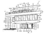
図1には、正面側から見た住宅1の外観が示されている。住宅1の正面とは、外観上において象徴的な面(ファサード)を表わし、典型的には屋外の通路に面する。本実施の形態では、たとえば、玄関扉50aが設けられた外壁の表面側を正面側という。   FIG. 1 shows the appearance of the house 1 as seen from the front side. The front of the house 1 represents a symbolic surface (facade) in appearance, and typically faces an outdoor passage. In the present embodiment, for example, the surface side of the outer wall provided with the entrance door 50a is referred to as the front side.

住宅1は、たとえば、都市部など比較的狭小地に建てられる3階建ての建物である。本実施の形態の住宅1は、敷地の略全体に建てられており、住宅1の周囲に、専用の庭は存在しないと想定する。   The house 1 is, for example, a three-story building built in a relatively small area such as an urban area. It is assumed that the house 1 according to the present embodiment is built on substantially the entire site, and there is no dedicated garden around the house 1.

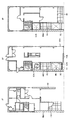
図2〜図4には、住宅1の1〜3階それぞれの間取り例が示されている。各階の居住空間の構成は、たとえば次の通りである。図1および図2に示されるように、住宅1の1階には、玄関(土間)50、玄関ホール51、および居室52が設けられている。玄関50および玄関ホール51は非居室である。図1および図3に示されるように、住宅1の2階には、居室としてのキッチン53およびリビング54、ならびに、非居室としてのパウダールーム55などが設けられている。図1および図4に示されるように、住宅1の3階には、ベッドルーム等、4つの居室56〜59が設けられている。居住空間は、外壁に囲まれた建物本体の屋内に位置する空間であり、居室および非居室を含む。   2 to 4 show floor plans for the first to third floors of the house 1. The structure of the living space on each floor is, for example, as follows. As shown in FIGS. 1 and 2, the first floor of the house 1 is provided with an entrance (between soil) 50, an entrance hall 51, and a living room 52. The entrance 50 and the entrance hall 51 are non-residential rooms. As shown in FIG. 1 and FIG. 3, a kitchen 53 and a living 54 as living rooms, a powder room 55 as a non-living room, and the like are provided on the second floor of the house 1. As shown in FIGS. 1 and 4, four rooms 56 to 59 such as a bedroom are provided on the third floor of the house 1. The living space is a space located inside the building body surrounded by the outer wall, and includes a living room and a non-living room.

本実施の形態に係る住宅1は、そのファサード、および、エントランス空間に特徴を有している。また、住宅1は、3階分の高さを有する半屋外吹抜け空間63を備えている。これらの特徴点について、以下に詳細に説明する。   The house 1 according to the present embodiment is characterized by its facade and entrance space. Moreover, the house 1 is provided with a semi-outdoor atrium space 63 having a height of three floors. These feature points will be described in detail below.

(ファサードについて)
正面から見た住宅1の外観について説明する。図1等において、住宅1の横方向を矢印A1で示している。また、図2等において、住宅1の前後方向(奥行方向)のうち前方を矢印A2で示している。なお、本実施の形態において、正面側を前方あるいは手前側ともいい、その反対側を奥側、背面側、あるいは後方ともいう。また、正面から見て右側が横方向一方側、左側が横方向他方側であるものとして説明する。
(About the facade)
The external appearance of the house 1 viewed from the front will be described. In FIG. 1 etc., the horizontal direction of the house 1 is indicated by an arrow A1. Moreover, in FIG. 2 etc., the front is shown by arrow A2 among the front-back direction (depth direction) of the house 1. In the present embodiment, the front side is also referred to as the front side or the near side, and the opposite side is also referred to as the back side, the back side, or the back side. Further, the description will be made assuming that the right side is the one side in the horizontal direction and the left side is the other side in the horizontal direction when viewed from the front.

住宅1は、2階と3階との間に、水平方向に延在する偏平形状の庇部(第1の庇部)41を有している。庇部41は、厚みの大きいスラブ状の大型庇である。庇部41は、正面外壁よりも両側方(横方向両側)に突出している。そのため、住宅1は、2階以下と3階とに分断されたような独創的なデザインとなっている。   The house 1 has a flat-shaped collar part (first collar part) 41 extending in the horizontal direction between the second floor and the third floor. The collar part 41 is a large slab-shaped collar having a large thickness. The collar part 41 protrudes in the both sides (lateral direction both sides) rather than the front outer wall. Therefore, the house 1 has an original design that is divided into the second floor and below and the third floor.

住宅1の正面外壁は、庇部41の下方に配置される外壁11〜13と、庇部41の上方に配置される外壁14,15とで構成されている。   The front outer wall of the house 1 is composed of outer walls 11 to 13 disposed below the collar part 41 and outer walls 14 and 15 disposed above the collar part 41.

外壁11は、2階分の高さを有しており、1階部分に玄関扉50aが設けられている。外壁11の屋内側には、後述するように、玄関50を含むエントランス空間が配置されている。外壁11の表面は、住宅1の正面外壁の基準面であり、1階から2階まで段差なく連続している。以下、外壁11の表面を、基準外壁面(第1の外壁面)21という。外壁11(基準外壁面21)の2階部分には、透光性を有する窓部210が設けられている。窓部210は、たとえば開閉できないフィックス窓である。   The outer wall 11 has a height of two floors, and an entrance door 50a is provided on the first floor portion. An entrance space including the entrance 50 is disposed on the indoor side of the outer wall 11 as described later. The surface of the outer wall 11 is a reference plane of the front outer wall of the house 1 and is continuous from the first floor to the second floor without a step. Hereinafter, the surface of the outer wall 11 is referred to as a reference outer wall surface (first outer wall surface) 21. A window portion 210 having translucency is provided on the second floor portion of the outer wall 11 (reference outer wall surface 21). The window part 210 is a fixed window that cannot be opened or closed, for example.

外壁12および外壁13は、外壁11の右隣に配置されている。外壁12は、外壁13よりも上方位置に配置されている。外壁12の屋内側には、2階の居住空間(たとえばキッチン53およびリビング54)が配置されている。外壁13の屋内側には、1階の居住空間(たとえば居室52)が配置されている。   The outer wall 12 and the outer wall 13 are arranged on the right side of the outer wall 11. The outer wall 12 is disposed at a position higher than the outer wall 13. On the indoor side of the outer wall 12, a second-floor living space (for example, a kitchen 53 and a living room 54) is arranged. On the indoor side of the outer wall 13, a first-floor living space (for example, a living room 52) is arranged.

ここで、外壁12の表面は、庇部41から吊下げられるように設けられた箱状体30の表面(正面)を構成している。以下、外壁12の表面を、2階外壁面(第2の外壁面)22という。2階外壁面22は、基準外壁面21よりも手前に位置している。図5には、前後方向における基準外壁面21の位置がラインL1で示され、前後方向における2階外壁面22の位置がラインL2で示されている。2階外壁面22は、基準外壁面21の位置から90cm以上前方に張り出している。   Here, the surface of the outer wall 12 constitutes the surface (front surface) of the box-shaped body 30 provided so as to be suspended from the flange portion 41. Hereinafter, the surface of the outer wall 12 is referred to as a second floor outer wall surface (second outer wall surface) 22. The second floor outer wall surface 22 is located in front of the reference outer wall surface 21. 5, the position of the reference outer wall surface 21 in the front-rear direction is indicated by a line L1, and the position of the second floor outer wall surface 22 in the front-rear direction is indicated by a line L2. The second-floor outer wall surface 22 projects more than 90 cm forward from the position of the reference outer wall surface 21.

箱状体30は、2階外壁面22と、地面から上方に離間して位置する底面31とを含む。底面31は、2階外壁面22の下端部と直交(交差)する。なお、地面は、住宅1のグランドレベルよりも嵩上げされたコンクリートの上面であってもよい。   The box-shaped body 30 includes a second-floor outer wall surface 22 and a bottom surface 31 that is spaced upward from the ground. The bottom surface 31 is orthogonal to (intersects) the lower end of the second floor outer wall surface 22. The ground may be an upper surface of concrete raised above the ground level of the house 1.

2階外壁面22の横幅寸法は、基準外壁面21の横幅寸法よりも十分に大きく、2倍以上であることが望ましい。外壁12(2階外壁面22)には、透光性を有する窓部220が設けられている。窓部220は、外壁12の略全幅に亘って設けられている。窓部220は、たとえば、2階外壁面22の横幅方向に沿って連続して設けられた複数の窓(すなわち連窓)によって構成されている。各窓は、開閉可能であってもよいし、開閉不能であってもよい。箱状体30の具体的な構成例については、後述する。   The lateral width dimension of the second floor outer wall surface 22 is preferably sufficiently larger than the lateral width dimension of the reference outer wall surface 21 and is twice or more. A window 220 having translucency is provided on the outer wall 12 (the second floor outer wall surface 22). The window part 220 is provided over substantially the entire width of the outer wall 12. The window part 220 is comprised by the several window (namely, continuous window) provided continuously along the horizontal width direction of the 2nd floor outer wall surface 22, for example. Each window may be openable or closable, and may not be openable. A specific configuration example of the box-shaped body 30 will be described later.

外壁13の表面は、箱状体30の底面31に直交している。以下、外壁13の表面を1階外壁面(第4の外壁面)23という。1階外壁面23は、図5に示されるように、基準外壁面21よりもさらに奥側の位置に配置されている。また、1階外壁面23の横幅寸法は、2階外壁面22の横幅寸法よりも小さい。外壁13(1階外壁面23)にも、透光性を有する窓部230が設けられている。窓部230は、たとえば掃出し窓である。   The surface of the outer wall 13 is orthogonal to the bottom surface 31 of the box-shaped body 30. Hereinafter, the surface of the outer wall 13 is referred to as a first floor outer wall surface (fourth outer wall surface) 23. As shown in FIG. 5, the first-floor outer wall surface 23 is arranged at a position on the back side of the reference outer wall surface 21. The lateral dimension of the first floor outer wall surface 23 is smaller than the lateral dimension of the second floor outer wall surface 22. The outer wall 13 (the first floor outer wall surface 23) is also provided with a window 230 having translucency. The window part 230 is a sweep window, for example.

外壁14は、庇部41を挟んで、外壁11の上に位置している。外壁14の屋内側には、3階の居住空間(たとえば居室57)が配置されている。図5に示されるように、前後方向における外壁14の表面の位置は、基準外壁面21と同じ位置であり、これらの面は、同一平面上に延在している。以下、外壁14の表面を3階外壁面24という。3階外壁面24の横幅寸法は、基準外壁面21の横幅寸法と略等しい。   The outer wall 14 is located on the outer wall 11 with the flange 41 interposed therebetween. On the indoor side of the outer wall 14, a residential space (for example, a living room 57) on the third floor is arranged. As shown in FIG. 5, the position of the surface of the outer wall 14 in the front-rear direction is the same position as the reference outer wall surface 21, and these surfaces extend on the same plane. Hereinafter, the surface of the outer wall 14 is referred to as a third floor outer wall surface 24. The width dimension of the third floor outer wall surface 24 is substantially equal to the width dimension of the reference outer wall surface 21.

外壁15は、外壁14の右隣であって、庇部41を挟んで外壁12の上方に位置している。外壁15の屋内側には、3階の居住空間(たとえば居室56)が配置されている。図5に示されるように、外壁15の表面は、3階外壁面24よりも手前に位置するが、2階外壁面22よりも奥側に位置している。以下、外壁15の表面を3階外壁面(第3の外壁面)25という。3階外壁面25の横幅寸法は、左横の3階外壁面24の横幅寸法よりも若干大きいが、2階外壁面22の横幅寸法よりも小さい。   The outer wall 15 is adjacent to the right of the outer wall 14 and is located above the outer wall 12 with the flange 41 interposed therebetween. On the indoor side of the outer wall 15, a residential space (for example, a living room 56) on the third floor is arranged. As shown in FIG. 5, the surface of the outer wall 15 is located in front of the third floor outer wall surface 24, but is located in the back side of the second floor outer wall surface 22. Hereinafter, the surface of the outer wall 15 is referred to as a third floor outer wall surface (third outer wall surface) 25. The width dimension of the third floor outer wall surface 25 is slightly larger than the width dimension of the left third floor outer wall surface 24, but is smaller than the width dimension of the second floor outer wall surface 22.

外壁14(3階外壁面24)および外壁15(3階外壁面25)にも、透光性を有する窓部240,250がそれぞれ設けられている。外壁14および外壁15は、庇部41上に設けられたバルコニー68に面している。そのため、窓部240,250は、たとえば掃出し窓である。なお、本実施の形態において、バルコニーとは、床部を有する半屋外空間であり、ベランダを含む概念である。   The outer wall 14 (third floor outer wall surface 24) and the outer wall 15 (third floor outer wall surface 25) are also provided with light-transmitting windows 240 and 250, respectively. The outer wall 14 and the outer wall 15 face a balcony 68 provided on the collar part 41. Therefore, the window parts 240 and 250 are sweep windows, for example. In the present embodiment, the balcony is a semi-outdoor space having a floor and is a concept including a veranda.

住宅1は、正面側の外壁面の前後方向位置を異ならせているだけではなく、各外壁面に窓部を設けているため、開放的な明るい印象となっている。また、箱状体30の表面である2階外壁面22においては、その全幅に亘り、高さのある窓部220が設けられている。したがって、住宅1のファサードは、軽快なイメージとなっている。なお、窓部220は、2階外壁面22の横方向(幅方向)端部との間に多少の隙間(たとえば10cm以下)を有して配置されていてもよい。   The house 1 has not only the front and rear positions of the outer wall surface in the front-rear direction but also a window portion on each outer wall surface. The second floor outer wall surface 22 which is the surface of the box-shaped body 30 is provided with a window portion 220 having a height over the entire width. Therefore, the facade of the house 1 has a light image. In addition, the window part 220 may be arrange | positioned with a some clearance gap (for example, 10 cm or less) between the horizontal direction (width direction) edge part of the 2nd floor outer wall surface 22. FIG.

ここで、2階外壁面22は、基準外壁面21と同様に平面状(フラット)である。そのため、箱状体30は、2階外壁面22および底面31と交差する側面32,33をさらに有している。図3に示されるように、側面32は、外壁12の右端部に直交する外壁(右側壁)81の表面を構成している。側面33は、外壁11の右端部と外壁12の左端部とに直交する外壁82の表面を構成している。   Here, the second floor outer wall surface 22 is flat (flat) like the reference outer wall surface 21. Therefore, the box-shaped body 30 further has side surfaces 32 and 33 that intersect the second floor outer wall surface 22 and the bottom surface 31. As shown in FIG. 3, the side surface 32 constitutes the surface of the outer wall (right side wall) 81 orthogonal to the right end portion of the outer wall 12. The side surface 33 constitutes the surface of the outer wall 82 orthogonal to the right end portion of the outer wall 11 and the left end portion of the outer wall 12.

これらの外壁81,82にも、外壁12の窓部220と同じ高さの窓部320,330が設けられている。つまり、箱状体30においては、表面の窓部220および両側面の窓部320,330によって、平面視においてU字状(コの字状)の連窓が構成されている。そのため、外観上、箱状体30は、浮いたガラスの箱のように見え、軽快感が向上されている。また、箱状体30内の居住空間(リビング54)が、正面側だけでなく奥の方まで光溢れる明るい空間になるとともに、箱状体30内の居住空間においては、屋外の景色を270度見渡すことができる。   These outer walls 81 and 82 are also provided with window portions 320 and 330 having the same height as the window portion 220 of the outer wall 12. That is, in the box-shaped body 30, a U-shaped (U-shaped) continuous window is configured in plan view by the window portion 220 on the surface and the window portions 320 and 330 on both side surfaces. Therefore, in appearance, the box-like body 30 looks like a floating glass box, and the lightness is improved. In addition, the living space (living 54) in the box-shaped body 30 becomes a bright space full of light not only in the front side but also in the back, and in the living space in the box-shaped body 30, the outdoor scenery is 270 degrees. Can overlook.

なお、2階外壁面22は、平面状でなくてもよく、たとえば円弧状など湾曲していてもよい。このような場合、箱状体30は、側面32,33を有していなくてもよい。   The second floor outer wall surface 22 does not have to be planar, and may be curved, for example, in an arc shape. In such a case, the box-shaped body 30 may not have the side surfaces 32 and 33.

箱状体30は、袖壁43,44によって下方から支持されている。袖壁43,44は、地面から箱状体30の底面31にまで上方に延在する支持体である。支持体は、柱であってもよい。袖壁43は、1階外壁面23よりも前方位置であって、箱状体30の底面31の右端部に接続されている。袖壁44は、1階外壁面23よりも前方位置であって、箱状体30の底面31の左端部に接続されている。袖壁43,44の厚みおよび横幅は同じであり、これらは互いに平行に配置されている。   The box-shaped body 30 is supported from below by sleeve walls 43 and 44. The sleeve walls 43 and 44 are supports that extend upward from the ground to the bottom surface 31 of the box-shaped body 30. The support may be a pillar. The sleeve wall 43 is located in front of the first floor outer wall surface 23 and is connected to the right end portion of the bottom surface 31 of the box-shaped body 30. The sleeve wall 44 is located in front of the first floor outer wall surface 23 and is connected to the left end portion of the bottom surface 31 of the box-shaped body 30. The thickness and width of the sleeve walls 43 and 44 are the same, and these are arranged in parallel to each other.

袖壁43,44間には支持体がなく、袖壁43,44によって挟まれる箱状体30の下方空間は、ピロティ空間60となっている。ピロティ空間60は、少なくとも正面側において屋外空間に向けて開放されている。ピロティ空間60の一部は、インナーガレージとしての機能を果たしており、敷地を有効利用することができる。ピロティ空間60は、一部分において、背面側にも抜けている。   There is no support between the sleeve walls 43, 44, and the lower space of the box-shaped body 30 sandwiched between the sleeve walls 43, 44 is a piloti space 60. The piloti space 60 is open toward the outdoor space at least on the front side. A part of the piloty space 60 functions as an inner garage, and the site can be used effectively. Part of the piloty space 60 is also open on the back side.

袖壁43,44は、2階外壁面22よりも少し奥側の位置に配置されている。また、袖壁43,44の色は、2階外壁面22(および他の外壁面21,23〜25)よりも暗色である。したがって、正面から住宅1を見た場合、箱状体30が地面から浮き上がったような浮遊感を強調することができる。なお、色に限らず、袖壁43,44の外表面の素材を2階外壁面22と異ならせていてもよい。   The sleeve walls 43 and 44 are arranged at a position slightly behind the second floor outer wall surface 22. The sleeve walls 43 and 44 are darker than the second floor outer wall surface 22 (and the other outer wall surfaces 21, 23 to 25). Therefore, when the house 1 is viewed from the front, it is possible to emphasize the floating feeling that the box-shaped body 30 is lifted from the ground. In addition, the material of the outer surface of the sleeve walls 43 and 44 is not limited to the color, and the second floor outer wall surface 22 may be different.

箱状体30の表面には、窓部220として、同じ高さ寸法の縦長の窓が横一列に並べられている。窓部220の上端位置は、庇部41の下面412に近接している。たとえば、窓部220の上端高さと庇部41の下面高さ(外壁12の上端高さ)との差が、10cm以下である。これに対し、窓部220の下端位置は、外壁12の下端位置から比較的大きく離れている。つまり、図1に示されるように、窓部220は、外壁12において、上方に偏って設けられている。   On the surface of the box-shaped body 30, vertically long windows having the same height are arranged in a horizontal row as the window portion 220. The upper end position of the window portion 220 is close to the lower surface 412 of the flange portion 41. For example, the difference between the upper end height of the window portion 220 and the lower surface height of the flange portion 41 (the upper end height of the outer wall 12) is 10 cm or less. On the other hand, the lower end position of the window 220 is relatively far away from the lower end position of the outer wall 12. That is, as shown in FIG. 1, the window portion 220 is provided on the outer wall 12 so as to be biased upward.

ここで、窓部220の下端位置と2階外壁面22の下端位置との間の高さ寸法H2は、庇部41の厚み寸法H1と略等しいことが望ましい。具体的には、これらの寸法に差が無いか、あったとしても10cm以下、あるいは、2割以下である。なお、庇部41の厚み寸法とは、その前端面(正面)411の高さ寸法を表わすものとする。庇部41の厚み寸法は、たとえば40cm以上である。   Here, it is desirable that the height dimension H2 between the lower end position of the window part 220 and the lower end position of the second floor outer wall surface 22 is substantially equal to the thickness dimension H1 of the flange part 41. Specifically, there is no difference in these dimensions, or even if it is 10 cm or less, or 20% or less. In addition, the thickness dimension of the collar part 41 shall represent the height dimension of the front-end surface (front surface) 411. The thickness dimension of the collar part 41 is 40 cm or more, for example.

住宅1は、さらに、3階外壁面25の上端部から前方に突出する庇部(第2の庇部)42を備えている。この庇部42も、庇部41と同様に偏平形状であり、その厚み寸法H3も、庇部41の厚み寸法H1と略等しい。庇部42は、3階外壁面25の左右端部よりも両側方に突出しているが、庇部42の横幅は、庇部41よりも短い。庇部42の前端面421の位置は、庇部41の前端面411よりも奥である。住宅1の屋根は、典型的には陸屋根であり、本実施の形態における庇部42は、陸屋根から部分的に突出した軒として構成されている。   The house 1 further includes a collar portion (second collar portion) 42 that protrudes forward from the upper end portion of the third-floor outer wall surface 25. The flange 42 is also flat like the flange 41, and its thickness dimension H3 is substantially equal to the thickness dimension H1 of the flange 41. Although the collar part 42 protrudes in the both sides rather than the right-and-left end part of the 3rd floor outer wall surface 25, the lateral width of the collar part 42 is shorter than the collar part 41. The position of the front end surface 421 of the collar portion 42 is deeper than the front end surface 411 of the collar portion 41. The roof of the house 1 is typically a flat roof, and the flange 42 in the present embodiment is configured as an eave partially protruding from the flat roof.

このように、2階外壁面22のうち窓部220がない下端部分の高さ寸法H2と、屋根付近の庇部42の厚み寸法存H3とを、存在感のある庇部41の厚み寸法H1と同等にすることで、外観において、軽快感を生じさせつつ、安定感のある落ち着いた印象も生じさせることができる。   Thus, the height dimension H2 of the lower end portion of the second floor outer wall surface 22 without the window portion 220 and the thickness dimension H3 of the collar portion 42 near the roof are the thickness dimension H1 of the collar portion 41 having a presence. By making it equivalent to the above, it is possible to produce a calm and calm impression while generating a light feeling in appearance.

庇部41は、基準外壁面21および2階外壁面22の上端部から前方に突出しているが、図1に示されるように、庇部41の前端面411は、左端部から右端部まで真直ぐに延びる平面状である。そのため、庇部41の前方への突出寸法は、2階外壁面22からの突出寸法よりも、基準外壁面21からの突出寸法の方が十分に大きい。   Although the collar part 41 protrudes ahead from the upper end part of the reference | standard outer wall surface 21 and the 2nd floor outer wall surface 22, as FIG. 1 shows, the front-end surface 411 of the collar part 41 is straight from a left end part to a right end part. It is the planar shape extended to. Therefore, the protrusion dimension from the reference outer wall surface 21 is sufficiently larger than the protrusion dimension from the second floor outer wall surface 22 as the protrusion dimension to the front side of the flange portion 41.

そこで、庇部41のうち、基準外壁面21に交差する奥行きの大きい部分は、2階分の高さを有する袖壁45によって、下方から支持されている。袖壁45は、地面から庇部41の下面412にまで上方に延びる支持体である。支持体は、柱であってもよい。袖壁45は、箱状体30下の袖壁43,44と平行に配置されている。袖壁45の外表面の色または素材は、袖壁43,44と同じである。そのため、高さのある袖壁45が設けられていても、違和感なく全体の雰囲気に馴染んでいる。袖壁45の前端位置は、2階外壁面22よりも手前に位置していてもよい。   Therefore, a portion of the collar portion 41 having a large depth that intersects the reference outer wall surface 21 is supported from below by a sleeve wall 45 having a height of two floors. The sleeve wall 45 is a support body that extends upward from the ground to the lower surface 412 of the collar portion 41. The support may be a pillar. The sleeve wall 45 is disposed in parallel with the sleeve walls 43 and 44 under the box-shaped body 30. The color or material of the outer surface of the sleeve wall 45 is the same as that of the sleeve walls 43 and 44. Therefore, even if the sleeve wall 45 with a height is provided, it is familiar with the whole atmosphere without a sense of incongruity. The front end position of the sleeve wall 45 may be positioned in front of the second floor outer wall surface 22.

袖壁45は、庇部41の左端部を支持し、箱状体30の側面33およびその下の袖壁44から離れた位置に配置されている。これにより、基準外壁面21の前方には、2階分の高さを有する屋外吹抜け空間61が形成される。屋外吹抜け空間61は、基準外壁面21と、袖壁45と、箱状体30の側面33および袖壁44とによって、三方が囲まれた空間である。袖壁45は、正面から見て玄関扉50aおよび窓部210とは重ならない位置に配置されている。袖壁45は、基準外壁面21から前方に離れて配置されていてもよい。   The sleeve wall 45 supports the left end portion of the collar portion 41 and is disposed at a position away from the side surface 33 of the box-shaped body 30 and the sleeve wall 44 below it. Thereby, an outdoor atrium space 61 having a height of two floors is formed in front of the reference outer wall surface 21. The outdoor atrium space 61 is a space surrounded on three sides by the reference outer wall surface 21, the sleeve wall 45, the side surface 33 of the box-shaped body 30 and the sleeve wall 44. The sleeve wall 45 is disposed at a position where it does not overlap the entrance door 50 a and the window portion 210 when viewed from the front. The sleeve wall 45 may be disposed away from the reference outer wall surface 21 in the forward direction.

このように、住宅1の玄関前空間には、2階分の高さを有する袖壁45が、外壁11から独立して立設されており、この袖壁45に隣接して屋外吹抜け空間61が配置されている。したがって、住宅1の玄関前空間は、開放的な雰囲気とともに重厚感あるいは高級感が生じ、上質な暮らしを予感させることができる。また、袖壁45は敷地境界に沿って配置されるため、袖壁45によって隣地の居住者の視線を遮ることができる。   As described above, the sleeve wall 45 having a height of two floors is erected independently of the outer wall 11 in the front space of the house 1, and the outdoor atrium space 61 is adjacent to the sleeve wall 45. Is arranged. Therefore, the space in front of the entrance of the house 1 has a profound feeling or a high-class feeling as well as an open atmosphere, so that a high quality living can be predicted. Moreover, since the sleeve wall 45 is disposed along the site boundary, the sleeve wall 45 can block the line of sight of the resident in the adjacent land.

なお、屋外吹抜け空間61は、上部が庇部41で覆われ、かつ、基準外壁面21と袖壁45と箱状体30の側面33および袖壁44とによって三方が囲まれた空間であることとしたが、限定的ではない。屋外吹抜け空間は、基準外壁面21に面し、かつ、上部が庇部41で覆われており、さらに、少なくともその左右一方側が壁面で区切られた空間であればよい。   The outdoor atrium space 61 is a space whose upper part is covered with the flange 41 and three sides are surrounded by the reference outer wall surface 21, the sleeve wall 45, the side surface 33 of the box-shaped body 30, and the sleeve wall 44. However, it is not limited. The outdoor atrium space may be a space that faces the reference outer wall surface 21 and is covered at its upper portion with the flange portion 41 and at least one of the left and right sides thereof is partitioned by the wall surface.

(エントランス空間について)
住宅1のエントランス空間について説明する。
(About entrance space)
The entrance space of the house 1 will be described.

玄関扉50aが設けられた外壁11の屋内側に位置するエントランス空間は、2階分の高さを有する吹抜け空間となっている。具体的には、図2および図3に示されるように、1階の玄関50および玄関ホール51とその上方空間とが、屋内吹抜け空間62を形成している。つまり、屋内吹抜け空間62は、玄関50および玄関ホール51の床面から2階天井面まで上方に延在し、住宅1のエントランス空間を構成している。このように、外壁11は、屋外吹抜け空間61と屋内吹抜け空間62との間に位置しているため、住宅1の建物本体に入る前だけでなく入った後も、開放的な雰囲気を味わうことができる。   The entrance space located on the indoor side of the outer wall 11 provided with the entrance door 50a is an atrium space having a height of two floors. Specifically, as shown in FIGS. 2 and 3, the entrance 50 and the entrance hall 51 on the first floor and the upper space form an indoor atrium 62. That is, the indoor atrium space 62 extends upward from the floor surface of the entrance 50 and the entrance hall 51 to the ceiling surface of the second floor, and constitutes the entrance space of the house 1. Thus, since the outer wall 11 is located between the outdoor atrium space 61 and the indoor atrium space 62, it can be enjoyed not only before entering the building body of the house 1 but also after entering. Can do.

図6には、正面側から見た屋外吹抜け空間61と、外壁11の奥に広がる屋内吹抜け空間62とが概念的に示されている。なお、図6には、理解の容易のために、外壁11から玄関扉50aおよび窓部210が取り除かれた状態が示されている。   FIG. 6 conceptually shows an outdoor atrium space 61 viewed from the front side and an indoor atrium space 62 extending in the back of the outer wall 11. FIG. 6 shows a state in which the entrance door 50a and the window part 210 are removed from the outer wall 11 for easy understanding.

図6に示されるように、屋内吹抜け空間62の天井面622と、屋外吹抜け空間61の天井面としての庇部41の下面412とは、略面一である。具体的には、これらの面の高さに差が無いか、あったとしても10cm以下である。これにより、屋外吹抜け空間61と屋内吹抜け空間62との間に一体感が生じる。   As shown in FIG. 6, the ceiling surface 622 of the indoor atrium space 62 and the lower surface 412 of the flange 41 as the ceiling surface of the outdoor atrium space 61 are substantially flush. Specifically, there is no difference in the heights of these surfaces, or even if they are 10 cm or less. Thereby, a sense of unity occurs between the outdoor atrium space 61 and the indoor atrium space 62.

また、屋内吹抜け空間62の天井面622と庇部41の下面412とは、視覚的に一続きとなるように、屋内吹抜け空間62の天井面622の色または柄は、庇部41の下面412の色または柄と連続していることが望ましい。典型的には、これらの面の色は同一であり、これらの面を構成する柄(たとえば木目)が同じ規則性を持って連続的に表れている。本実施の形態では、庇部41の下面412および屋内吹抜け空間62の天井面622の柄は、所定幅の板の継ぎ目が屋外側から屋内側へ向かって真っすぐ延びるように形成されている。なお、これらの面の素材は異なっていてもよい。   Further, the color or pattern of the ceiling surface 622 of the indoor atrium space 62 is the lower surface 412 of the heel portion 41 so that the ceiling surface 622 of the indoor atrium space 62 and the lower surface 412 of the heel portion 41 are visually connected. It is desirable to be continuous with the color or pattern. Typically, the colors of these surfaces are the same, and the patterns (for example, wood grain) constituting these surfaces appear continuously with the same regularity. In the present embodiment, the pattern of the lower surface 412 of the collar portion 41 and the ceiling surface 622 of the indoor atrium space 62 is formed such that the joint of a plate having a predetermined width extends straight from the outdoor side toward the indoor side. Note that the materials of these surfaces may be different.

さらに、図1および図6に示されるように、外壁11の窓部210の上端位置は、庇部41の下面412に近接している。たとえば、窓部210の上端高さと庇部41の下面高さ(外壁11の上端高さ)との差が、10cm以下である。窓部210は、たとえば大型のフィックス窓によって構成される。したがって、屋外吹抜け空間61側から住宅1を見た場合、この窓部210を通して屋内吹抜け空間62への拡がりが期待でき、贅沢な雰囲気を演出することができる。   Further, as shown in FIGS. 1 and 6, the upper end position of the window portion 210 of the outer wall 11 is close to the lower surface 412 of the flange portion 41. For example, the difference between the upper end height of the window portion 210 and the lower surface height of the flange portion 41 (the upper end height of the outer wall 11) is 10 cm or less. The window part 210 is comprised by the large sized fixed window, for example. Therefore, when the house 1 is viewed from the outdoor atrium space 61 side, expansion to the indoor atrium space 62 can be expected through the window portion 210, and a luxurious atmosphere can be produced.

ここで、図2、図3、および図6に示されるように、屋内吹抜け空間62には、1階の居住空間と2階の居住空間との間の移動のために階段71が配置されている。階段71は、屋内吹抜け空間62の床面621(玄関ホール51の床面)から、渡り廊下72へと繋がっている。つまり、階段71の上り口は玄関ホール51に設けられ、階段71の下り口は渡り廊下72に設けられている。階段71は、たとえば直線状であり、外壁11の左端部に直交する外壁(左側壁)83に沿って配置されている。   Here, as shown in FIGS. 2, 3, and 6, a staircase 71 is disposed in the indoor atrium space 62 for movement between the first-floor living space and the second-floor living space. Yes. The stairs 71 are connected from the floor surface 621 of the indoor atrium space 62 (the floor surface of the entrance hall 51) to the crossing corridor 72. That is, the ascending entrance of the stairs 71 is provided in the entrance hall 51, and the descending entrance of the stairs 71 is provided in the crossing corridor 72. The staircase 71 is linear, for example, and is disposed along an outer wall (left side wall) 83 orthogonal to the left end portion of the outer wall 11.

図3および図6に示されるように、渡り廊下72は、屋内吹抜け空間62を横切るように、外壁11に沿って配置されている。渡り廊下72の一方の端部は、外壁(左側壁)83に接続され、渡り廊下72の他方の端部は、2階の居住空間(たとえばリビング54)の床部に接続されている。   As shown in FIGS. 3 and 6, the passage hallway 72 is arranged along the outer wall 11 so as to cross the indoor atrium space 62. One end of the transfer corridor 72 is connected to the outer wall (left side wall) 83, and the other end of the transfer corridor 72 is connected to the floor of the second-floor living space (for example, the living room 54).

また、階段71は、渡り廊下72の一方の端部側に接続されている。より具体的には、階段71の下り口は、渡り廊下72の両側部のうち、奥側の側部72aに設けられている。渡り廊下72は、外壁11から離間して配置されていることが望ましい。この場合、渡り廊下72の手前側の側部72bには、たとえば、落下を防止するための手摺が設けられる。   The staircase 71 is connected to one end side of the crossing corridor 72. More specifically, the descending exit of the staircase 71 is provided in the side part 72 a on the back side among the both side parts of the passageway 72. The transit hallway 72 is preferably disposed away from the outer wall 11. In this case, for example, a handrail for preventing the fall is provided on the side portion 72b on the front side of the passageway 72.

このように、渡り廊下72は、玄関50または玄関ホール51上であって、外壁11に設けられた窓部210の奥に配置されている。そのため、居住者が渡り廊下72に立つと、窓部210を介して、外壁11の向こうにある屋外吹抜け空間61全体を眺めることができる。   As described above, the passage hallway 72 is disposed on the entrance 50 or the entrance hall 51 and behind the window 210 provided on the outer wall 11. Therefore, when the resident stands in the crossing corridor 72, the entire outdoor atrium space 61 beyond the outer wall 11 can be viewed through the window portion 210.

本実施の形態の階段71は、直線状であり、玄関ホール51の奥から手前に向かって上り切る形状となっている。また、外壁11の窓部210が、階段71の上り切り方向の延長線上に配置されている。そのため、階段71を上っている途中から、外壁11の窓部210を通して空(屋外吹抜け空間61の上方部分)が見える。また、階段71を上り切ると、窓部210越しに屋外吹抜け空間61全体を自然と望むことができ、ゆったりとした気分を味わうことができる。   The stairs 71 of the present embodiment is linear and has a shape that rises from the back of the entrance hall 51 toward the front. Further, the window part 210 of the outer wall 11 is arranged on an extension line in the up and down direction of the stairs 71. Therefore, the sky (the upper portion of the outdoor atrium space 61) can be seen through the window 210 of the outer wall 11 from the middle of going up the stairs 71. Moreover, when going up the stairs 71, the whole outdoor atrium space 61 can be naturally seen through the window part 210, and a relaxed feeling can be tasted.

さらに、外壁11の窓部210は、屋内吹抜け空間62の天井面622(つまり、庇部41の下面412)付近にまで上方に延在しており、屋内吹抜け空間62の天井面622と庇部41の下面412とが一体感を有している。そのため、階段71を上り切って渡り廊下72に立つと、屋内吹抜け空間62の天井面622が窓部210を超えて屋外にまで延出しているように見え、居住者は屋内(居住空間)においても開放感を得ることができる。   Further, the window portion 210 of the outer wall 11 extends upward to the vicinity of the ceiling surface 622 of the indoor atrium space 62 (that is, the lower surface 412 of the flange portion 41), and the ceiling surface 622 of the indoor atrium space 62 and the flange portion The lower surface 412 of 41 has a sense of unity. Therefore, when standing on the corridor 72 after going up the stairs 71, the ceiling surface 622 of the indoor atrium space 62 appears to extend beyond the window portion 210 to the outside, and the resident is also indoors (residential space). An open feeling can be obtained.

なお、階段71は、直線状でなくてもよく、たとえば折返し階段などであってもよい。その場合であっても、階段71の上り切り方向の延長線上に窓部210が配置されていることが望ましい。具体的には、階段71の下り口は、渡り廊下72の奥側の側部72aに設けられていることが望ましい。言い換えると、1階の玄関ホール51(屋内吹抜け空間62の床)から階段71を上り切ると、窓部210(外壁11)側に視線が向く位置に、渡り廊下72が配置されていることが望ましい。   The staircase 71 may not be linear, and may be a folded staircase, for example. Even in such a case, it is desirable that the window portion 210 be disposed on the extended line of the staircase 71 in the up-and-down direction. Specifically, it is desirable that the descending exit of the staircase 71 is provided in the side portion 72 a on the back side of the passageway 72. In other words, it is desirable that the crossing corridor 72 is arranged at a position where the line of sight faces the window 210 (outer wall 11) side when going up the stairs 71 from the entrance hall 51 on the first floor (the floor of the indoor atrium space 62). .

また、階段71は渡り廊下72に接続されていることとしたが、限定的ではない。すなわち、階段71を上り切った場所で窓部210を望めることができれば、階段71の下り口のある2階の床面は、渡り廊下72の床面でなくてもよい。   Moreover, although the staircase 71 was connected to the crossing corridor 72, it is not limited. In other words, if the window 210 can be seen at the place where the staircase 71 is climbed up, the floor surface on the second floor where the downstairs of the staircase 71 does not have to be the floor surface of the passageway 72.

また、本実施の形態では、階段71の下り口の先に(すなわち、階段71の上り切り方向の延長線上に)窓部210が配置されている構成を示したが、階段71を上り切った所に窓部210が位置していればよく、たとえば、階段71の下り口の横に窓部210が配置されていてもよい。   Further, in the present embodiment, the configuration in which the window part 210 is arranged at the tip of the descending entrance of the staircase 71 (that is, on the extended line in the up and down direction of the staircase 71) is shown. For example, the window part 210 may be disposed beside the descending entrance of the stairs 71.

(半屋外吹抜け空間について)
住宅1が備える半屋外吹抜け空間63について説明する。
(About semi-outdoor atrium space)
The semi-outdoor atrium space 63 provided in the house 1 will be described.

図1〜図4に示されるように、半屋外吹抜け空間63は、複数階に亘って上下方向に延在し、上部が屋外空間(空)に向けて開放された吹抜け空間である。   As shown in FIGS. 1 to 4, the semi-outdoor atrium space 63 is an atrium space that extends in the vertical direction over a plurality of floors and has an upper portion opened toward the outdoor space (empty).

半屋外吹抜け空間63は、地面から3階部分にまで上下方向に延在する外郭側壁46に隣接して配置されている。外郭側壁46は、半屋外吹抜け空間63の右側に位置し、住宅1の敷地境界に沿って設けられている。また、外郭側壁46は、住宅1の背面側の端部に配置されている。外郭側壁46は、屋外空間から見た場合、屋根付近の庇部42の高さまで上方に延在している。   The semi-outdoor atrium space 63 is disposed adjacent to the outer side wall 46 extending in the vertical direction from the ground to the third floor. The outer side wall 46 is located on the right side of the semi-outdoor atrium space 63 and is provided along the site boundary of the house 1. Further, the outer side wall 46 is disposed at an end portion on the back side of the house 1. The outer side wall 46 extends upward to the height of the flange 42 near the roof when viewed from the outdoor space.

外郭側壁46は、2階正面の外壁12よりも奥側に配置されており、正面側から見て外壁12によって隠されている。具体的には、図3を参照して、外郭側壁46は、外壁12に平行な外壁84に直交するように配置されている。外壁84は、箱状体30を構成する2階右側面の外壁81に直交している。また、外郭側壁46は、箱状体30を支持する袖壁43と平面視において同一ライン上に(前後方向に沿って)配置されており、外郭側壁46の外表面の色または素材は、袖壁43と同じであってもよい。   The outer side wall 46 is disposed behind the outer wall 12 in front of the second floor, and is hidden by the outer wall 12 when viewed from the front side. Specifically, referring to FIG. 3, the outer side wall 46 is arranged so as to be orthogonal to the outer wall 84 parallel to the outer wall 12. The outer wall 84 is orthogonal to the outer wall 81 on the right side of the second floor constituting the box-shaped body 30. Further, the outer side wall 46 is arranged on the same line (along the front-rear direction) with the sleeve wall 43 supporting the box-shaped body 30 in plan view, and the color or material of the outer surface of the outer side wall 46 is the sleeve It may be the same as the wall 43.

外郭側壁46は、1〜3階それぞれにおいて、半屋外吹抜け空間63を挟み、建物本体の外壁85,86,87に対面している。すなわち、半屋外吹抜け空間63は、1階の外壁85に面する1階空間63aと、2階の外壁86に面する2階空間63bと、3階の外壁87に面するおよび3階空間63cとで構成されている。   The outer side wall 46 faces the outer walls 85, 86, and 87 of the building body with the semi-outdoor atrium space 63 sandwiched between the first to third floors. That is, the semi-outdoor atrium 63 has a first floor space 63a facing the first floor outer wall 85, a second floor space 63b facing the second floor outer wall 86, a third floor outer wall 87 and a third floor space 63c. It consists of and.

図2を参照して、1階の外壁85は、1階の正面外壁13と、背面の外壁とに直交している。1階の外壁85と外郭側壁46とで挟まれた空間のうち、前方側の部分に半屋外吹抜け空間63の1階空間63aが形成されており、残りの部分に、1階テラス部64が設けられている。そのため、半屋外吹抜け空間63の1階空間63aは、前方側および後方側の双方において、屋外空間に向けて開放されている。なお、1階テラス部64は、後述する2階バルコニー65の床部の下方に位置する空間である。1階テラス部64と半屋外空間63の1階空間63aとで、1階庭空間が形成されている。   Referring to FIG. 2, outer wall 85 on the first floor is orthogonal to front outer wall 13 on the first floor and outer wall on the back. Of the space sandwiched between the outer wall 85 and the outer side wall 46 of the first floor, the first floor space 63a of the semi-outdoor atrium space 63 is formed in the front portion, and the first floor terrace section 64 is formed in the remaining portion. Is provided. Therefore, the first floor space 63a of the semi-outdoor atrium space 63 is open toward the outdoor space on both the front side and the rear side. The first floor terrace section 64 is a space located below the floor section of the second floor balcony 65 described later. A first-floor garden space is formed by the first-floor terrace section 64 and the first-floor space 63 a of the semi-outdoor space 63.

具体的には、半屋外吹抜け空間63の1階空間63aの前方には、箱状体30下のピロティ空間60が仕切りなく配置され、1階空間63aの後方には、1階テラス部64が仕切りなく配置されている。図2に示されるように、1階の外壁85には、少なくとも半屋外吹抜け空間63の1階空間63aに面する位置に、透光性を有する窓部850(たとえば掃出し窓)が設けられている。   Specifically, in the front of the first floor space 63a of the semi-outdoor atrium space 63, a piloti space 60 below the box-shaped body 30 is arranged without partitioning, and behind the first floor space 63a is a first floor terrace portion 64. Arranged without partitions. As shown in FIG. 2, the outer wall 85 on the first floor is provided with a light-transmitting window portion 850 (for example, a sweep window) at least at a position facing the first floor space 63 a of the semi-outdoor atrium space 63. Yes.

住宅1の1階をこのような構成とすることにより、1階テラス部64も、ピロティ空間60の一部のように見せることができる。また、ピロティ空間60においてその天井面(箱状体30の底面31を含む)を見た場合、天井面が一部、刳り貫かれたような斬新な構成となっている。   By configuring the first floor of the house 1 in such a configuration, the first-floor terrace portion 64 can also appear as a part of the piloty space 60. Further, when the ceiling surface (including the bottom surface 31 of the box-shaped body 30) is seen in the piloty space 60, the ceiling surface is partly pierced.

図3を参照して、2階の外壁86は、上述の外壁84と、背面の外壁とに直交している。2階の外壁86と外郭側壁46とで挟まれた空間のうち、後壁84側の部分に半屋外吹抜け空間63の2階空間63bが形成されており、残りの部分に、2階バルコニー65が設けられている。つまり、半屋外吹抜け空間63の2階空間63bは、後方側において屋外空間に向けて開放されている。   Referring to FIG. 3, the outer wall 86 on the second floor is orthogonal to the outer wall 84 and the outer wall on the back surface. Of the space sandwiched between the outer wall 86 and the outer side wall 46 on the second floor, the second floor space 63b of the semi-outdoor atrium 63 is formed on the rear wall 84 side, and the second floor balcony 65 is formed on the remaining portion. Is provided. That is, the second floor space 63b of the semi-outdoor atrium space 63 is open toward the outdoor space on the rear side.

2階の外壁86は、半屋外吹抜け空間63に面する位置に窓部860a(たとえばフィックス窓)を有し、2階バルコニー65に面する位置に窓部860b(掃出し窓)を有している。2階バルコニー65は、後述する3階バルコニー67の床部の下方に位置している。つまり、3階バルコニー67の床部が2階バルコニー65の屋根となっている。   The outer wall 86 on the second floor has a window portion 860a (for example, a fixed window) at a position facing the semi-outdoor atrium space 63, and has a window portion 860b (a sweep window) at a position facing the second-floor balcony 65. . The second-floor balcony 65 is located below the floor portion of the third-floor balcony 67 described later. That is, the floor of the third-floor balcony 67 is the roof of the second-floor balcony 65.

図4を参照して、3階の外壁87は、上述の正面外壁15と、背面の外壁とに直交している。3階の外壁87と外郭側壁46とで挟まれた空間のうち、中央部に半屋外吹抜け空間63の3階空間63cが形成されており、残りの部分(前方部分および後方部分)に3階バルコニー66,67が設けられている。つまり、半屋外吹抜け空間63の3階空間63cは、前方側および後方側の双方において、屋外空間に向けて開放されている。   Referring to FIG. 4, the outer wall 87 on the third floor is orthogonal to the front outer wall 15 and the rear outer wall. Of the space sandwiched between the outer wall 87 and the outer side wall 46 of the third floor, the third floor space 63c of the semi-outdoor atrium space 63 is formed in the central portion, and the remaining floor (the front portion and the rear portion) is the third floor. Balconies 66 and 67 are provided. That is, the third floor space 63c of the semi-outdoor atrium space 63 is open toward the outdoor space on both the front side and the rear side.

外郭側壁46の横幅(住宅1の前後方向の長さ寸法)は、3階部においてのみ他よりも大きくなっている。外郭側壁46の3階部における正面側への延長部分46aが、側方にまで回り込んだ庇部41の上面413上に立設されている。正面側の3階バルコニー66は、この延長部分46aに面している。   The lateral width of the outer side wall 46 (length dimension in the front-rear direction of the house 1) is larger than the others only on the third floor. An extended portion 46a to the front side of the third floor portion of the outer side wall 46 is erected on the upper surface 413 of the flange portion 41 that extends to the side. The front-side third-floor balcony 66 faces this extended portion 46a.

3階の外壁87は、半屋外吹抜け空間63に面する位置に窓部870a(たとえばフィックス窓)を有し、正面側の3階バルコニー66に面する位置に窓部870b(掃出し窓)を有し、背面側の3階バルコニー67に面する位置に窓部870c(掃出し窓)を有している。   The third-floor outer wall 87 has a window portion 870a (for example, a fixed window) at a position facing the semi-outdoor atrium space 63, and a window portion 870b (a sweep window) at a position facing the third-floor balcony 66 on the front side. In addition, a window portion 870c (sweeping window) is provided at a position facing the third-floor balcony 67 on the back side.

半屋外吹抜け空間63に隣接する2階および3階のバルコニー65〜67の床面は、それぞれ、外壁86,87に隣接する2階および3階の居住空間の床面と略面一となっている。したがって、外壁86,87を基準とした屋内外において床が連続しているような一体感が生じ、居住空間を開放感のある広い空間のように印象付けることができる。   The floor surfaces of the second and third floor balconies 65 to 67 adjacent to the semi-outdoor atrium space 63 are substantially flush with the floor surfaces of the second and third floor living spaces adjacent to the outer walls 86 and 87, respectively. Yes. Therefore, a sense of unity that the floors are continuous indoors and outdoors with respect to the outer walls 86 and 87 is generated, and the living space can be impressed as a wide space with an open feeling.

上記のように、半屋外吹抜け空間63は、横方向において外壁85〜87と外郭側壁46との間に形成されている。また、2階および3階に、半屋外吹抜け空間63の後方側に隣接するバルコニー65,67がそれぞれ配置され、3階に半屋外吹抜け空間63の正面側に隣接するバルコニー66が配置されている。そのため、半屋外吹抜け空間63は、各階の境界部において、周囲が壁部で囲まれている。たとえば、1階と2階の境界部(2階の下端部)においては、半屋外吹抜け空間63は、右側の外郭側壁46、手前の外壁84、左側の外壁86、および奥側の2階バルコニー65の床部側壁によって、四周が囲まれている。なお、半屋外吹抜け空間63は、高さ方向(上下方向)における少なくとも一部が、壁部に囲まれていてればよい。   As described above, the semi-outdoor atrium space 63 is formed between the outer walls 85 to 87 and the outer side wall 46 in the lateral direction. Further, balconies 65 and 67 adjacent to the rear side of the semi-outdoor atrium space 63 are respectively arranged on the second floor and the third floor, and a balcony 66 adjacent to the front side of the semi-outdoor atrium space 63 is arranged on the third floor. . Therefore, the semi-outdoor atrium 63 is surrounded by a wall at the boundary of each floor. For example, at the boundary between the first floor and the second floor (the lower end of the second floor), the semi-outdoor atrium space 63 includes a right outer wall 46, a front outer wall 84, a left outer wall 86, and a second floor balcony on the back side. Four sides are surrounded by 65 floor side walls. In addition, at least a part of the semi-outdoor atrium space 63 in the height direction (vertical direction) only needs to be surrounded by a wall portion.

半屋外吹抜け空間63に面する各階の外壁85〜87には、透光性を有する窓部がそれぞれ設けられている。上述のように、半屋外吹抜け空間63は屋根がないため、半屋外吹抜け空間63に射し込まれた光は、窓部850,860a,870aを介してそれぞれの階の居住空間にまで採り入れられる。また、これらの窓部自体が開閉可能であるか、あるいは、その隣の窓部が開閉可能であるため、都市においても、光、風、空を身近に感じることができる。   Translucent windows are provided on the outer walls 85 to 87 of each floor facing the semi-outdoor atrium space 63. As described above, since the semi-outdoor atrium space 63 has no roof, the light incident on the semi-outdoor atrium space 63 is taken into the living space of each floor through the window portions 850, 860a, and 870a. . In addition, since these windows themselves can be opened or closed, or the windows next to the windows can be opened and closed, it is possible to feel light, wind, and sky in a city.

たとえば、半屋外吹抜け空間63に樹木73が植えられている場合、1階の外壁85に隣接する居住空間(居室52)において、樹木73の幹を望むことができる。そのため、外壁85際の居住空間を、余暇を愉しめる落ち着いた居場所とすることができる。また、2階の外壁86に隣接する居住空間(リビング54等)においては、樹木73の葉によって光や風の揺らぎを感じることができる。したがって、外壁86際の居住空間を、家族と集う心地良い居場所とすることができる。また、3階の外壁87に隣接する居住空間(居室56,59等)において、空に延びる樹木73の息吹を感じることができる。そのため、外壁87際の居住空間を、リラックスできる爽快な居場所とすることができる。   For example, when the tree 73 is planted in the semi-outdoor atrium space 63, the trunk of the tree 73 can be desired in the living space (the living room 52) adjacent to the outer wall 85 on the first floor. Therefore, the living space near the outer wall 85 can be a calm place to enjoy leisure. Further, in the living space (such as the living room 54) adjacent to the outer wall 86 on the second floor, the leaves of the trees 73 can feel light and wind fluctuations. Therefore, the living space near the outer wall 86 can be a comfortable place to gather with the family. Further, in the living space (such as the living rooms 56 and 59) adjacent to the outer wall 87 on the third floor, it is possible to feel the breath of the trees 73 extending into the sky. Therefore, the living space near the outer wall 87 can be an exhilarating place to relax.

また、窓部850,860a,870aに対面する位置に外郭側壁46が設けられているため、隣人の視線を気にすることなく半屋外吹抜け空間63に設けた樹木73を鑑賞することができる。また、外郭側壁46に現れる外壁85〜87の陰影により、半屋外吹抜け空間63の情景をより身近に感じることができる。   In addition, since the outer side wall 46 is provided at a position facing the windows 850, 860a, and 870a, the tree 73 provided in the semi-outdoor atrium space 63 can be appreciated without worrying about the line of sight of the neighbor. In addition, the scene of the semi-outdoor atrium space 63 can be felt closer due to the shadows of the outer walls 85 to 87 appearing on the outer side wall 46.

このように、本実施の形態の住宅1によれば、家族は様々な角度から自然を愉しみ、互いに気配を感じながら暮らすことができる。つまり、1階から3階まで上下方向に延在する半屋外吹抜け空間63と、各階において前後方向のうち少なくともいずれか一方に、屋外空間に繋がる半屋外空間(ピロティ空間60、1階テラス部64、バルコニー65〜68)が隣接して配置されている。そのため、半屋外吹抜け空間63とこれら半屋外空間とが、各階において自然と家族とをつなぐ立体庭園として位置付けられている。   Thus, according to the house 1 of the present embodiment, the family can enjoy nature from various angles and live while feeling attentive to each other. That is, the semi-outdoor atrium 63 extending in the vertical direction from the first floor to the third floor, and the semi-outdoor space (the pilotity space 60, the first-floor terrace section 64) connected to the outdoor space in at least one of the front and rear directions on each floor. , Balconies 65-68) are arranged adjacent to each other. Therefore, the semi-outdoor atrium 63 and these semi-outdoor spaces are positioned as a three-dimensional garden that connects nature and the family on each floor.

さらに、半屋外吹抜け空間63の1階空間63aおよび3階空間63cは、前後方向双方において屋外空間に向けて開放されているのに対し、2階空間63bは後方側のみ屋外空間に向けて開放されている。すなわち、屋外吹抜け空間63の2階空間63bは、正面外壁12に隣接して配置される居住空間(たとえばキッチン53)よりも奥側に配置されている。したがって、正面から住宅1を見た場合に、半屋外吹抜け空間63の2階空間63bは正面外壁12(箱状体30)によって隠されるため、半屋外吹抜け空間63の存在が目立たず、バランスのよい外観となっている。   Furthermore, the first floor space 63a and the third floor space 63c of the semi-outdoor atrium space 63 are open toward the outdoor space in both the front and rear directions, whereas the second floor space 63b is open toward the outdoor space only on the rear side. Has been. That is, the second floor space 63b of the outdoor atrium space 63 is arranged on the back side of the living space (for example, the kitchen 53) arranged adjacent to the front outer wall 12. Therefore, when the house 1 is viewed from the front, the second-floor space 63b of the semi-outdoor atrium space 63 is hidden by the front outer wall 12 (the box-shaped body 30). It has a good appearance.

また、半屋外吹抜け空間63に背の高い樹木73を設けている場合には、樹木73の幹は正面から見えるため、樹木73が住宅1の2階の居住空間を突き抜けているような、面白味のある雰囲気を演出することができる。なお、半屋外吹抜け空間63の1階空間63aは、少なくとも正面側が屋外空間に向けて開放されていればよく、背面側には外壁が配置されていてもよい。   Moreover, when the tall tree 73 is provided in the semi-outdoor atrium space 63, the trunk of the tree 73 can be seen from the front, so that the tree 73 penetrates the living space on the second floor of the house 1 and is interesting. It can produce a certain atmosphere. In addition, at least the front side of the first floor space 63a of the semi-outdoor atrium space 63 may be open toward the outdoor space, and an outer wall may be disposed on the back side.

さらに、正面側の庇部42は、正面側の3階バルコニー67を超えて外郭側壁46よりも側方に突出している。つまり、庇部42は、バルコニー67の上方空間を一部覆っていてもよい。また、庇部42は、外郭側壁46の上端部から側方に向けて突出する側面側の庇部47と一体的に連結されている。そのため、正面から見た場合に、3階上部に配置されたL字状の庇部42,47によって、半屋外吹抜け空間63の3階空間63cの存在感も抑えられている。また、3階上部の庇部42,47をこのように配置することで、箱状体30上の存在感のある庇部41とのバランスも良い。したがって、本実施の形態の住宅1によれば、軽快さと重厚感とを両立させることができる。   Furthermore, the front side collar part 42 protrudes to the side from the outer side wall 46 beyond the third floor balcony 67 on the front side. That is, the collar part 42 may partially cover the space above the balcony 67. Further, the flange portion 42 is integrally connected to a flange portion 47 on the side surface side protruding from the upper end portion of the outer side wall 46 toward the side. Therefore, when viewed from the front, the presence of the third-floor space 63c of the semi-outdoor atrium 63 is suppressed by the L-shaped flanges 42 and 47 arranged at the upper part of the third floor. Moreover, the arrangement | positioning with the collar part 41 with the presence on the box-shaped body 30 is good by arrange | positioning the collar parts 42 and 47 of the 3rd floor upper part in this way. Therefore, according to the house 1 of the present embodiment, both lightness and profound feeling can be achieved.

(変形例)
上記住宅1は、ファサードの特徴として、箱状体30が、庇部41に吊下げられるように設けられていたが、限定的ではない。つまり、箱状体30の直上に庇部41が配置されていなくてもよい。図7は、本実施の形態の変形例に係る住宅1Aの正面側の外観を示す図である。図8は、住宅1Aの各階の平面図である。図8においては、前後方向における箱状体30Aの正面(2階外壁面)の位置が想像線で示されている。
(Modification)
The house 1 is provided as a feature of the facade such that the box-shaped body 30 is suspended from the collar 41, but is not limited. That is, the collar part 41 does not need to be disposed immediately above the box-shaped body 30. FIG. 7 is a diagram showing an appearance on the front side of a house 1A according to a modification of the present embodiment. FIG. 8 is a plan view of each floor of the house 1A. In FIG. 8, the position of the front surface (outer wall surface of the second floor) of the box-shaped body 30A in the front-rear direction is indicated by an imaginary line.

住宅1Aは、図1等に示した住宅1と同様に3階建てであるが、箱状体30A上の庇部41はなく、屋根付近に大型の庇部47が1つ設けられているだけである。箱状体30Aの正面の外壁12Aは、庇部と交差しておらず、箱状体30Aの上に3階のバルコニー95が設けられている。   The house 1A has a three-story structure like the house 1 shown in FIG. 1 and the like, but there is no collar 41 on the box-shaped body 30A, and only one large collar 47 is provided near the roof. It is. The outer wall 12A in front of the box-shaped body 30A does not intersect with the buttock, and a balcony 95 on the third floor is provided on the box-shaped body 30A.

また、変形例においては、住宅1Aの左端に、敷地境界に沿って、3階分以上の高さを有する外郭側壁46Aが立設されている。すなわち、外郭側壁46Aは、玄関扉50aが設けられた外壁11Aに交差して配置されている。外郭側壁46Aの高さは、住宅1Aの建物本体の屋根高さよりも高く、庇部47が外郭側壁46Aに突き当たるように、両者が直交している。   In the modification, an outer side wall 46A having a height of three floors or more is erected along the site boundary at the left end of the house 1A. That is, the outer side wall 46A is arranged so as to intersect the outer wall 11A provided with the entrance door 50a. The height of the outer side wall 46A is higher than the height of the roof of the building body of the house 1A, and the two are orthogonal to each other so that the flange portion 47 hits the outer side wall 46A.

また、箱状体30Aの下には、底面31の右端部側に接続される袖壁43が配置されているが、底面31の左端部側に接続される袖壁は配置されていない。その代わりに、箱状体30Aの左側面を構成する外壁82Aから左方向に延びる胴差92が、外郭側壁46Aに接続されている。つまり、外壁82Aと外郭側壁46Aとの間に、胴差92が架け渡されている。より具体的には、2階床を支持する胴差92と、3階床を支持する胴差92とが、外壁82Aと外郭側壁46Aとの間の空間90を横切るように配置されている。   Further, a sleeve wall 43 connected to the right end side of the bottom surface 31 is disposed under the box-shaped body 30A, but a sleeve wall connected to the left end portion side of the bottom surface 31 is not disposed. Instead, a trunk difference 92 extending leftward from the outer wall 82A constituting the left side surface of the box-shaped body 30A is connected to the outer side wall 46A. That is, the trunk difference 92 is bridged between the outer wall 82A and the outer side wall 46A. More specifically, the trunk difference 92 supporting the second floor and the trunk difference 92 supporting the third floor are arranged so as to cross the space 90 between the outer wall 82A and the outer side wall 46A.

これらの胴差92は、縦格子91によって隠されている。縦格子91は、下側の胴差92の下端から上側の胴差92の上端にまで上方に延びており、側壁82Aと外郭側壁46Aとの間の空間90を覆っている。なお、図1に示した住宅1に備えられた屋外吹抜け空間61は、その前方を胴差が横切る構成ではないため、住宅1の玄関前空間は、住宅1Aの玄関前空間よりも明るく開放的である。   These trunk differences 92 are hidden by the vertical lattice 91. The vertical lattice 91 extends upward from the lower end of the lower barrel difference 92 to the upper end of the upper barrel difference 92, and covers the space 90 between the side wall 82A and the outer side wall 46A. In addition, since the outdoor atrium space 61 provided in the house 1 shown in FIG. 1 is not configured to cross the front of the torso, the space in front of the entrance of the house 1 is brighter and more open than the space in front of the entrance of the house 1A. It is.

本変形例においては、玄関扉50aが設けられた外壁11Aは1階分の高さしかなく、外壁11Aの上に2階のバルコニー93の床部が配置される例を示しているが、上記実施形態の住宅1と同様に、玄関扉50aが設けられた外壁11Aは、1階から2階まで連続して設けられていてもよい。   In this modification, the outer wall 11A provided with the entrance door 50a is only one floor high, and an example in which the floor portion of the balcony 93 on the second floor is arranged on the outer wall 11A is shown above. Similarly to the house 1 of the embodiment, the outer wall 11A provided with the entrance door 50a may be provided continuously from the first floor to the second floor.

また、2階のバルコニー93および3階のバルコニー94の奥側に、上部が屋外空間に開放された半屋外吹抜け空間63Aが配置されていることとしたが、上記実施の形態の住宅1と同様に、半屋外吹抜け空間63Aは、正面外壁に隣接して配置される居住空間よりも奥側に配置されていてもよい。   In addition, the semi-outdoor atrium space 63A with the upper part opened to the outdoor space is arranged on the back side of the balcony 93 on the second floor and the balcony 94 on the third floor, but it is the same as the house 1 of the above embodiment. Moreover, the semi-outdoor atrium space 63 </ b> A may be disposed on the back side of the living space disposed adjacent to the front outer wall.

以上説明した本実施の形態およびその変形例によれば、プライバシーを確保しながら、建物内の居住空間において自然を身近に感じることができる。また、軽快感と重厚感とを兼ね備えたモダンかつ独創的な外観となっている。そのため、都市部においても、余暇を愉しむ贅沢な住まいを提供することができる。   According to the present embodiment and its modification described above, nature can be felt closer to the living space in the building while ensuring privacy. In addition, it has a modern and original appearance that combines lightness and profound feeling. Therefore, even in urban areas, it is possible to provide a luxurious residence that enjoys leisure.

なお、住宅1(1A)は、3階建てであることとしたが、複数階建てであればよく、たとえば、2階建または4階建であってもよい。この場合、箱状体30が設けられる階(特定階)は、地上階(1階)よりも上の階であれば、2階でなくてもよい。いずれの場合であっても、外郭側壁46および半屋外吹抜け空間63は、地上階(1階)から最上階まで延在していることが望ましい。   In addition, although the house 1 (1A) was decided to be 3 stories, what is necessary is just multi-storey, for example, 2 stories or 4 stories may be sufficient. In this case, the floor (specific floor) on which the box-shaped body 30 is provided may not be the second floor as long as it is a floor above the ground floor (first floor). In any case, it is desirable that the outer side wall 46 and the semi-outdoor atrium space 63 extend from the ground floor (first floor) to the top floor.

また、基準外壁面21(外壁11)を住宅1の正面側として説明したが、限定的ではない。つまり、図1に示した住宅1の外観は、たとえば、住宅1の側面の外観であってもよい。具体的には、図1に示した基準の外壁11に玄関扉50aが設けられていなくてもよく、その場合、上述の外壁面21〜25は、同じ方向を向いていればよい。   Moreover, although the reference | standard outer wall surface 21 (outer wall 11) was demonstrated as the front side of the house 1, it is not limited. That is, the appearance of the house 1 illustrated in FIG. 1 may be, for example, the appearance of the side surface of the house 1. Specifically, the entrance door 50a may not be provided on the reference outer wall 11 shown in FIG. 1, and in this case, the outer wall surfaces 21 to 25 described above only need to face the same direction.

今回開示された実施の形態はすべての点で例示であって制限的なものではないと考えられるべきである。本発明の範囲は上記した説明ではなくて特許請求の範囲によって示され、特許請求の範囲と均等の意味および範囲内でのすべての変更が含まれることが意図される。   The embodiment disclosed this time should be considered as illustrative in all points and not restrictive. The scope of the present invention is defined by the terms of the claims, rather than the description above, and is intended to include any modifications within the scope and meaning equivalent to the terms of the claims.

1,1A 住宅、30,30A 箱状体、11〜15,81〜87,11A,12A,82A 外壁、21〜25 外壁面、210,220,230,240,250,320,330,850,860a,860b,870a,870b,870c 窓部、21 基準外壁面、22 2階外壁面、23 1階外壁面、24,25 3階外壁面、31 底面、32,33 側面、41,42,43,47 庇部、43,44,45 袖壁、46,46A 外郭側壁、50 玄関、50a 玄関扉、51 玄関ホール、52,53,56〜59 居室、53 キッチン、54 リビング、55 パウダールーム、60 ピロティ空間、61 屋外吹抜け空間、62 屋内吹抜け空間、63 半屋外吹抜け空間、64 1階テラス部、65〜68,93〜95 バルコニー、71 階段、72 渡り廊下、73 樹木、91 縦格子、92 胴差。   1,1A housing, 30, 30A box-shaped body, 11-15, 81-87, 11A, 12A, 82A outer wall, 21-25 outer wall surface, 210, 220, 230, 240, 250, 320, 330, 850, 860a , 860b, 870a, 870b, 870c Window portion, 21 Reference outer wall surface, 22 Second floor outer wall surface, 23 First floor outer wall surface, 24, 25 Third floor outer wall surface, 31 Bottom surface, 32, 33 Side surface, 41, 42, 43, 47 buttock, 43, 44, 45 sleeve wall, 46, 46A outer wall, 50 entrance, 50a entrance door, 51 entrance hall, 52, 53, 56-59 living room, 53 kitchen, 54 living, 55 powder room, 60 piloti Space, 61 outdoor atrium space, 62 indoor atrium space, 63 semi-outdoor atrium space, 64 1st floor terrace, 65-68, 93-95 bar Knee, 71 stairs, 72 corridor, 73 trees, 91 vertical grid, 92 cylinder difference.

Claims (8)

複数階に亘って連続して設けられた第1の外壁面と、
前記第1の外壁面の横方向一方側に隣接して配置される箱状体とを備え、
前記箱状体は、前記第1の外壁面よりも前方に位置し、透光性を有する窓部が設けられた第2の外壁面と、地面から上方に離間して位置し、前記第2の外壁面の下端部と交差する底面とを含み、
前記箱状体の下方に位置する空間の前方は、屋外空間に向けて開放されている、住宅。
A first outer wall surface provided continuously across a plurality of floors;
A box-like body disposed adjacent to one side in the lateral direction of the first outer wall surface,
The box-shaped body is located in front of the first outer wall surface, and is positioned away from the second outer wall surface provided with a light-transmitting window portion and from the ground, and the second Including a bottom surface intersecting a lower end portion of the outer wall surface of
The front of the space located under the box-like body is a house that is open to the outdoor space.
前記箱状体を下方から支持する支持体をさらに備え、
前記支持体は、前記第2の外壁面の位置よりも後方に配置されている、請求項1に記載の住宅。
A support for supporting the box-like body from below;
The house according to claim 1, wherein the support body is disposed rearward of the position of the second outer wall surface.
前記第1の外壁面および前記第2の外壁面の上端部から前方に突出する偏平形状の第1の庇部をさらに備え、
前記第1の庇部は、前記第2の外壁面よりも側方に突出している、請求項1または2に記載の住宅。
A flat first flange that protrudes forward from the upper ends of the first outer wall surface and the second outer wall surface;
The house according to claim 1 or 2, wherein the first flange portion protrudes laterally from the second outer wall surface.
前記第2の外壁面の略全幅に亘って設けられた窓部をさらに備え、
前記窓部の上端位置は、前記第1の庇部の下面に近接しており、
前記窓部の下端位置と前記第2の外壁面の下端位置との間の高さ寸法は、前記第1の庇部の厚み寸法と略等しい、請求項3に記載の住宅。
A window provided over substantially the entire width of the second outer wall surface,
The upper end position of the window part is close to the lower surface of the first flange part,
The house according to claim 3, wherein a height dimension between a lower end position of the window part and a lower end position of the second outer wall surface is substantially equal to a thickness dimension of the first flange part.
前記第1の庇部よりも上方に位置し、かつ、前記第2の外壁面よりも後方に位置する第3の外壁面と、
前記第3の外壁面の上端部から前方に突出する偏平形状の第2の庇部とをさらに備え、
前記第2の庇部の厚み寸法は、前記第1の庇部の厚み寸法と略等しい、請求項3または4に記載の住宅。
A third outer wall surface positioned above the first flange and positioned rearward of the second outer wall surface;
A flat second flange projecting forward from the upper end of the third outer wall surface;
The house according to claim 3 or 4, wherein a thickness dimension of the second collar part is substantially equal to a thickness dimension of the first collar part.
前記箱状体の下には、前記第1の外壁面よりも後方に位置する第4の外壁面をさらに備える、請求項1〜5のいずれかに記載の住宅。   The house according to any one of claims 1 to 5, further comprising a fourth outer wall surface located rearward of the first outer wall surface under the box-shaped body. 前記第1の外壁面には、玄関扉が設けられている、請求項1〜6のいずれかに記載の住宅。   The house according to any one of claims 1 to 6, wherein an entrance door is provided on the first outer wall surface. 前記第1の外壁面の横方向他方側において地面から上方に延在し、前記第1の外壁面に交差する外郭側壁と、
前記第2の外壁面よりも上方かつ後方に位置する第3の外壁面と、
前記第3の外壁面の上端部から前方に突出し、前記外郭側壁の側面に交差する第3の庇部とをさらに備える、請求項1または2に記載の住宅。
An outer side wall extending upward from the ground on the other lateral side of the first outer wall surface and intersecting the first outer wall surface;
A third outer wall surface located above and behind the second outer wall surface;
3. The house according to claim 1, further comprising: a third flange portion protruding forward from an upper end portion of the third outer wall surface and intersecting a side surface of the outer side wall.
JP2015254725A 2015-12-25 2015-12-25 Housing Pending JP2017115522A (en)

Priority Applications (1)

Application Number Priority Date Filing Date Title
JP2015254725A JP2017115522A (en) 2015-12-25 2015-12-25 Housing

Applications Claiming Priority (1)

Application Number Priority Date Filing Date Title
JP2015254725A JP2017115522A (en) 2015-12-25 2015-12-25 Housing

Publications (1)

Publication Number Publication Date
JP2017115522A true JP2017115522A (en) 2017-06-29

Family

ID=59233961

Family Applications (1)

Application Number Title Priority Date Filing Date
JP2015254725A Pending JP2017115522A (en) 2015-12-25 2015-12-25 Housing

Country Status (1)

Country Link
JP (1) JP2017115522A (en)

Cited By (1)

* Cited by examiner, † Cited by third party
Publication number Priority date Publication date Assignee Title
JP2019049108A (en) * 2017-09-08 2019-03-28 トヨタホーム株式会社 House

Citations (11)

* Cited by examiner, † Cited by third party
Publication number Priority date Publication date Assignee Title
JPS6247659U (en) * 1985-09-11 1987-03-24
JPH11200645A (en) * 1998-01-12 1999-07-27 Sekisui House Ltd Residence
JP2000160850A (en) * 1998-11-30 2000-06-13 Sekisui House Ltd House with garage
JP2001207657A (en) * 2000-01-25 2001-08-03 Asahi Kasei Corp Designing method for roof floor of house and mounting structure of roof floor structure
JP2002021432A (en) * 2000-07-10 2002-01-23 Asahi Kasei Corp Window structure of open ceiling room
JP2003184329A (en) * 2001-12-21 2003-07-03 Asahi Kasei Corp Residence with projecting section
JP2003227178A (en) * 2002-02-01 2003-08-15 Sekisui Chem Co Ltd Unit building with garage
JP2004346527A (en) * 2003-05-20 2004-12-09 Misawa Homes Co Ltd Wall structured building
JP2010121334A (en) * 2008-11-19 2010-06-03 Misawa Homes Co Ltd Building
JP2014201960A (en) * 2013-04-04 2014-10-27 旭化成ホームズ株式会社 Building
EP3031710A1 (en) * 2014-12-12 2016-06-15 Udvikling Danmark A/S Housing unit

Patent Citations (11)

* Cited by examiner, † Cited by third party
Publication number Priority date Publication date Assignee Title
JPS6247659U (en) * 1985-09-11 1987-03-24
JPH11200645A (en) * 1998-01-12 1999-07-27 Sekisui House Ltd Residence
JP2000160850A (en) * 1998-11-30 2000-06-13 Sekisui House Ltd House with garage
JP2001207657A (en) * 2000-01-25 2001-08-03 Asahi Kasei Corp Designing method for roof floor of house and mounting structure of roof floor structure
JP2002021432A (en) * 2000-07-10 2002-01-23 Asahi Kasei Corp Window structure of open ceiling room
JP2003184329A (en) * 2001-12-21 2003-07-03 Asahi Kasei Corp Residence with projecting section
JP2003227178A (en) * 2002-02-01 2003-08-15 Sekisui Chem Co Ltd Unit building with garage
JP2004346527A (en) * 2003-05-20 2004-12-09 Misawa Homes Co Ltd Wall structured building
JP2010121334A (en) * 2008-11-19 2010-06-03 Misawa Homes Co Ltd Building
JP2014201960A (en) * 2013-04-04 2014-10-27 旭化成ホームズ株式会社 Building
EP3031710A1 (en) * 2014-12-12 2016-06-15 Udvikling Danmark A/S Housing unit

Non-Patent Citations (1)

* Cited by examiner, † Cited by third party
Title
新「SKYE(スカイエ)」発売(ニュースリリース), JPN6020046278, 25 September 2015 (2015-09-25), pages 3, ISSN: 0004400095 *

Cited By (1)

* Cited by examiner, † Cited by third party
Publication number Priority date Publication date Assignee Title
JP2019049108A (en) * 2017-09-08 2019-03-28 トヨタホーム株式会社 House

Similar Documents

Publication Publication Date Title
KR101858026B1 (en) Flower garden building of forest cities and building group
JP6436130B2 (en) Residential
JP6483347B2 (en) building
JP6933904B2 (en) Housing
JP2017115522A (en) Housing
JP2017115524A (en) Housing
JP2017115523A (en) House
JP2006328738A (en) Building
JP2021167564A (en) building
JP6675148B2 (en) housing complex
JP6919637B2 (en) Housing
JP2008303570A (en) Building with balcony
KR20190116638A (en) Spatial structure of load-bearing wall type 4-bays apartment plan with each terrace court
JP2018150802A (en) Housing
JP2017166270A (en) building
JP7310150B2 (en) housing
JP2009121093A (en) Building
JP2008133649A (en) Building having daylighting storage structure part
JP2007177596A (en) Staircase structure
JP2013127181A (en) Dwelling house
JP7392560B2 (en) building with courtyard
CN218265142U (en) City forest garden house
CN218265143U (en) City forest garden house
JP7311379B2 (en) building
JP2012132311A (en) Building with balcony

Legal Events

Date Code Title Description
A80 Written request to apply exceptions to lack of novelty of invention

Free format text: JAPANESE INTERMEDIATE CODE: A80

Effective date: 20160118

A621 Written request for application examination

Free format text: JAPANESE INTERMEDIATE CODE: A621

Effective date: 20181203

A977 Report on retrieval

Free format text: JAPANESE INTERMEDIATE CODE: A971007

Effective date: 20191021

A131 Notification of reasons for refusal

Free format text: JAPANESE INTERMEDIATE CODE: A131

Effective date: 20191029

A521 Request for written amendment filed

Free format text: JAPANESE INTERMEDIATE CODE: A523

Effective date: 20191212

A131 Notification of reasons for refusal

Free format text: JAPANESE INTERMEDIATE CODE: A131

Effective date: 20200602

A521 Request for written amendment filed

Free format text: JAPANESE INTERMEDIATE CODE: A523

Effective date: 20200729

A131 Notification of reasons for refusal

Free format text: JAPANESE INTERMEDIATE CODE: A131

Effective date: 20201208

A02 Decision of refusal

Free format text: JAPANESE INTERMEDIATE CODE: A02

Effective date: 20210608