JP2021167564A - building - Google Patents

building Download PDF

Info

Publication number
JP2021167564A
JP2021167564A JP2021111953A JP2021111953A JP2021167564A JP 2021167564 A JP2021167564 A JP 2021167564A JP 2021111953 A JP2021111953 A JP 2021111953A JP 2021111953 A JP2021111953 A JP 2021111953A JP 2021167564 A JP2021167564 A JP 2021167564A
Authority
JP
Japan
Prior art keywords
wall
wall body
window
building
body portion
Prior art date
Legal status (The legal status is an assumption and is not a legal conclusion. Google has not performed a legal analysis and makes no representation as to the accuracy of the status listed.)
Granted
Application number
JP2021111953A
Other languages
Japanese (ja)
Other versions
JP7248746B2 (en
Inventor
豊樹 野口
Toyoki Noguchi
博隆 古賀
Hirotaka Koga
利咲 齋藤
Risaki Saito
Current Assignee (The listed assignees may be inaccurate. Google has not performed a legal analysis and makes no representation or warranty as to the accuracy of the list.)
Daiwa House Industry Co Ltd
Original Assignee
Daiwa House Industry Co Ltd
Priority date (The priority date is an assumption and is not a legal conclusion. Google has not performed a legal analysis and makes no representation as to the accuracy of the date listed.)
Filing date
Publication date
Application filed by Daiwa House Industry Co Ltd filed Critical Daiwa House Industry Co Ltd
Priority to JP2021111953A priority Critical patent/JP7248746B2/en
Publication of JP2021167564A publication Critical patent/JP2021167564A/en
Application granted granted Critical
Publication of JP7248746B2 publication Critical patent/JP7248746B2/en
Active legal-status Critical Current
Anticipated expiration legal-status Critical

Links

Images

Abstract

To provide a building capable of improving designability even without complication of a framework structure.SOLUTION: A building (1) comprises a roof (14), and an exterior wall part (12) on a specific story positioned below the roof. The exterior wall part (12) includes an upside wall body part (22) crossing the roof, and a downside wall body part (21) that is positioned below the upside wall body part. A surface of the upside wall body part (22), which is arranged in a position receding with respect to a surface of the downside wall body part (21), is different in at least one of a material and a color tone from a surface of the downside wall body part (21). The upside wall body part (22) comprises, for example, a band window (40).SELECTED DRAWING: Figure 1

Description

本発明は、住宅などの建物に関し、特に、軸組工法で造られた木造の建物に関する。 The present invention relates to a building such as a house, and more particularly to a wooden building constructed by a frame construction method.

従来から、外観意匠性を高めるために、外壁表面側に凹凸を設けた住宅が提案されている。 Conventionally, in order to enhance the appearance design, a house having irregularities on the surface side of the outer wall has been proposed.

たとえば、特開2013−127181号公報(特許文献1)には、上階の正面外壁に片持ちのオーバーハング部を設けた住宅が開示されている。また、特開2014−109117号公報(特許文献2)には、勾配屋根の妻側に配置される破風サッシと、その下の階のサッシとを上下に連続して設けることで、外観に外壁が出てこないようにした住宅建物が開示されている。 For example, Japanese Patent Application Laid-Open No. 2013-127181 (Patent Document 1) discloses a house in which a cantilever overhang portion is provided on the front outer wall of the upper floor. Further, in Japanese Patent Application Laid-Open No. 2014-109117 (Patent Document 2), a gable sash arranged on the gable side of a sloped roof and a sash on the floor below the gable sash are continuously provided vertically on the outer wall. Residential buildings that prevent the appearance of sashes are disclosed.

特開2013−127181号公報Japanese Unexamined Patent Publication No. 2013-127181 特開2014−109117号公報Japanese Unexamined Patent Publication No. 2014-109117

軸組工法で造られた建物において、特許文献1のように各階の外壁に凹凸を設ける場合、梁および柱を含む躯体部の構造、すなわち軸組構造が複雑となる。また、特許文献2のように、切妻屋根の妻側の面が窓だけで構成されていると、屋根の存在が強調されるものの、重厚感に欠ける。 In a building constructed by the frame construction method, when unevenness is provided on the outer wall of each floor as in Patent Document 1, the structure of the skeleton including beams and columns, that is, the frame structure becomes complicated. Further, as in Patent Document 2, when the gable-side surface of the gable roof is composed of only windows, the existence of the roof is emphasized, but the gable roof lacks a profound feeling.

本発明は、上記のような課題を解決するためになされたものであって、その目的は、軸組構造を複雑化しなくても、意匠性を向上させることのできる建物を提供することである。 The present invention has been made to solve the above problems, and an object of the present invention is to provide a building capable of improving design without complicating the framework structure. ..

この発明のある局面に従う建物は、屋根と、屋根の下方に位置する特定階の外壁部とを備える。外壁部は、屋根に交差する上側壁体部と、上側壁体部の下方に位置する下側壁体部とを含む。上側壁体部の表面は、下側壁体部の表面よりも後退した位置に配置され、かつ、下側壁体部の表面とは素材および色調の少なくとも一方が異なっている。 A building according to an aspect of the present invention comprises a roof and an outer wall portion of a particular floor located below the roof. The outer wall portion includes an upper side wall body portion that intersects the roof and a lower side wall body portion that is located below the upper side wall body portion. The surface of the upper side wall body portion is arranged at a position recessed from the surface of the lower side wall body portion, and at least one of the material and the color tone is different from the surface of the lower side wall body portion.

好ましくは、建物は、特定階の天井付近に配置された第1梁部材と、第1梁部材と平行に配置され、特定階の床を支持する第2梁部材とをさらに備え、外壁部が、第1梁部材および第2梁部材間において上下方向に延びる複数の柱を含む。この場合、下側壁体部は、柱よりも屋外側に設けられ、かつ、表面側に外装面部材を有する。上側壁体部は、柱間に固定された窓部と、窓部の側端部に隣接し、柱の屋外面を覆う柱被覆部とを含むことが望ましい。 Preferably, the building further includes a first beam member arranged near the ceiling of the specific floor and a second beam member arranged parallel to the first beam member and supporting the floor of the specific floor, and the outer wall portion has an outer wall portion. , Includes a plurality of columns extending in the vertical direction between the first beam member and the second beam member. In this case, the lower side wall body portion is provided on the outdoor side of the pillar and has an exterior surface member on the surface side. It is desirable that the upper side wall body portion includes a window portion fixed between the columns and a column covering portion adjacent to the side end portion of the window portion and covering the outdoor surface of the column.

好ましくは、上側壁体部が複数の窓部を含み、複数の窓部は、帯状に連ねられて連窓を構成する。連窓は、外壁部の略全幅に亘って延在していることが望ましい。 Preferably, the upper side wall body portion includes a plurality of window portions, and the plurality of window portions are connected in a strip shape to form a continuous window. It is desirable that the continuous window extends over substantially the entire width of the outer wall portion.

好ましくは、屋根は、外壁部の上端部に交差する軒天井を有する。この場合、窓部の奥に位置する室内空間の天井と軒天井とは、同じ色調であり、かつ、略面一であることが望ましい。 Preferably, the roof has an eaves ceiling that intersects the top edge of the outer wall. In this case, it is desirable that the ceiling of the indoor space located at the back of the window and the ceiling of the eaves have the same color tone and are substantially flush with each other.

建物は、外壁部の側端部に交差する側方外壁部をさらに備えている。側方外壁部には、上側壁体部の窓部と連続的に設けられた側方窓部が設けられていてもよい。 The building further comprises a lateral outer wall that intersects the side end of the outer wall. The side outer wall portion may be provided with a side window portion that is continuously provided with the window portion of the upper side wall body portion.

好ましくは、柱は、上側壁体部が固定される上側柱と、下側壁体部が固定される下側柱とを有する。建物は、上側柱と下側柱との間に位置する第3梁部材をさらに備え、第3梁部材と第2梁部材と一対の下側柱とで構成される枠体に、耐力要素が設けられていることが望ましい。 Preferably, the column has an upper column to which the upper side wall body portion is fixed and a lower column to which the lower side wall body portion is fixed. The building is further provided with a third beam member located between the upper column and the lower column, and a load bearing element is provided in a frame composed of the third beam member, the second beam member, and a pair of lower columns. It is desirable that it is provided.

好ましくは、下側壁体部は、外装面部材に加え、柱の屋外面に沿って配置された内側面部材と、外装面部材および内側面部材の間に設けられた通気層とを有している。この場合、上側壁体部の表面は、内側面部材の厚み範囲内に位置していることが望ましい。 Preferably, the lower side wall body portion has, in addition to the exterior surface member, an inner surface member arranged along the outdoor surface of the column, and a ventilation layer provided between the exterior surface member and the inner surface member. There is. In this case, it is desirable that the surface of the upper side wall body portion is located within the thickness range of the inner side surface member.

好ましくは、特定階が、地上階よりも上の階である。この場合、建物は、外壁部の側方側において、外壁部と同じ方向を向いて配置されたバルコニーの立壁部と、バルコニーの上に位置するバルコニー天井とをさらに備えていてもよい。この場合、立壁部の上端とバルコニー天井との間の間隔は、上側壁体部の高さ寸法と略等しいことが望ましい。 Preferably, the specific floor is a floor above the ground floor. In this case, the building may further include a standing wall portion of the balcony arranged so as to face the same direction as the outer wall portion and a balcony ceiling located above the balcony on the side side of the outer wall portion. In this case, it is desirable that the distance between the upper end of the vertical wall portion and the balcony ceiling is substantially equal to the height dimension of the upper side wall body portion.

この発明の他の局面に従う住宅は、上記いずれかに記載の建物を備える。住宅は、外壁部の前方において、外壁部と略平行に配置された外構壁と、外構壁の上端との間に間隔をあけて配置された外構天井とを備えることが望ましい。 A house according to another aspect of the present invention comprises the building described in any of the above. It is desirable that the house is provided with an exterior wall arranged substantially parallel to the outer wall portion and an exterior ceiling arranged at a distance between the upper end of the outer wall portion in front of the outer wall portion.

本発明によれば、軸組構造を複雑化しなくても、意匠性を向上させることができる。 According to the present invention, the design can be improved without complicating the framework structure.

本発明の実施の形態1に係る建物の正面側の外観図である。It is an external view of the front side of the building which concerns on Embodiment 1 of this invention. 本発明の実施の形態1に係る建物の縦断面を部分的に示す図であり、図1のII−II線に沿う断面図である。It is a figure which shows the vertical section of the building which concerns on Embodiment 1 of this invention partially, and is the sectional view which follows the line II-II of FIG. 本発明の実施の形態1に係る建物における、連窓の配置形状を模式的に示す平面図である。It is a top view which shows typically the arrangement shape of the continuous window in the building which concerns on Embodiment 1 of this invention. 本発明の実施の形態1に係る建物の側面を模式的に示す図である。It is a figure which shows typically the side surface of the building which concerns on Embodiment 1 of this invention. 本発明の実施の形態1において、2階外壁部の要部を示す縦断面図であり、図2のV部分を拡大して示す図である。In Embodiment 1 of this invention, it is the vertical sectional view which shows the main part of the 2nd floor outer wall part, and is the figure which enlarges and shows the V part of FIG. 本発明の実施の形態1において、2階外壁部のうちの上部外壁部の横断面を部分的に示す図であり、図3のVI部分を拡大して示す図である。In the first embodiment of the present invention, it is a figure which shows the cross section of the upper outer wall part of the 2nd floor outer wall part partially, and is the figure which enlarges and shows the VI part of FIG. 本発明の実施の形態1において、側方窓部の位置における側方外壁部の横断面を部分的に示す図であり、図3のVII部分を拡大して示す図である。In Embodiment 1 of this invention, it is the figure which shows the cross section of the side outer wall part at the position of the side window part partially, and is the figure which shows the VII part of FIG. 3 enlarged. 本発明の実施の形態1において、水切部材の通気口の構成例を模式的に示す図であり、図5の矢印VIIIの方向から見た水切部材の屋外側端部の図である。In Embodiment 1 of this invention, it is the figure which shows typically the structural example of the vent of the drainage member, and is the figure of the outdoor side end part of the drainage member seen from the direction of the arrow VIII of FIG. 本発明の実施の形態1における2階外壁部の軸組構造の一例を模式的に示す図である。It is a figure which shows typically an example of the frame structure of the 2nd floor outer wall part in Embodiment 1 of this invention. 第1の比較例における特定階の外壁部の軸組構造を模式的に示す図である。It is a figure which shows typically the frame structure of the outer wall part of the specific floor in the 1st comparative example. 第2の比較例における特定階の外壁部の軸組構造を模式的に示す図である。It is a figure which shows typically the frame structure of the outer wall part of the specific floor in the 2nd comparative example. 本発明の実施の形態1に係る建物における、連窓の他の配置例を示す図である。It is a figure which shows the other arrangement example of the continuous window in the building which concerns on Embodiment 1 of this invention. 本発明の実施の形態1に係る建物における、連窓のさらに他の配置例を示す図である。It is a figure which shows the other arrangement example of the continuous window in the building which concerns on Embodiment 1 of this invention. 本発明の実施の形態1の変形例に係る建物の構成例を模式的に示す側面図である。It is a side view which shows typically the structural example of the building which concerns on the modification of Embodiment 1 of this invention. 本発明の実施の形態2に係る住宅の正面側の外観図である。It is an external view of the front side of the house which concerns on Embodiment 2 of this invention. 公知の建物における外壁部の構造とその通気経路とを模式的に示す縦断面図である。It is a vertical cross-sectional view which shows typically the structure of the outer wall part in a known building and its ventilation path.

本発明の実施の形態について図面を参照しながら詳細に説明する。なお、図中同一または相当部分には同一符号を付してその説明は繰返さない。 Embodiments of the present invention will be described in detail with reference to the drawings. The same or corresponding parts in the drawings are designated by the same reference numerals, and the description thereof will not be repeated.

<実施の形態1>
(概要について)
図1および図2を参照して、本実施の形態に係る建物1の概要について説明する。
<Embodiment 1>
(About the outline)
An outline of the building 1 according to the present embodiment will be described with reference to FIGS. 1 and 2.

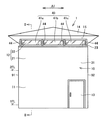
本実施の形態に係る建物1は、柱と梁を用いた軸組工法で造られた木造の住宅である。建物1は、たとえば2階建てであり、図1には、建物1の正面側の外観が示されている。なお、建物1の正面とは、外観上において象徴的な面(ファサード)を表わし、典型的には屋外の通路に面する。本実施の形態では、たとえば、玄関扉13が設けられた外壁の表面側を正面側という。 The building 1 according to the present embodiment is a wooden house constructed by a frame construction method using columns and beams. The building 1 is, for example, a double-decker building, and FIG. 1 shows the appearance of the front side of the building 1. The front surface of the building 1 represents a symbolic surface (façade) in appearance, and typically faces an outdoor passageway. In the present embodiment, for example, the surface side of the outer wall provided with the entrance door 13 is referred to as the front side.

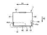
建物1は、平面視において略矩形形状であり、正面側の外壁部10と、外壁部10の両側端部に交差する側方外壁部91,92と、側方外壁部91,92に交差し、外壁部10と平行な背面外壁部とを有している。側方外壁部91は、外壁部10の横幅方向一方側(紙面上左側)に配置され、側方外壁部92は、外壁部10の横幅方向他方側(紙面上右側)に配置されている。図1には、外壁部10の横幅方向が矢印A1として示され、図2には、外壁部10の内外方向(厚み方向)のうちの屋外方向(すなわち正面側)が矢印A2として示されている。なお、屋外方向を前方、屋内方向を後方ともいう。 The building 1 has a substantially rectangular shape in a plan view, and intersects the outer wall portion 10 on the front side, the lateral outer wall portions 91, 92 intersecting both side ends of the outer wall portion 10, and the side outer wall portions 91, 92. It has a back outer wall portion parallel to the outer wall portion 10. The lateral outer wall portion 91 is arranged on one side (left side on the paper surface) of the outer wall portion 10 in the lateral width direction, and the lateral outer wall portion 92 is arranged on the other side (right side on the paper surface) of the outer wall portion 10 in the lateral width direction. In FIG. 1, the lateral width direction of the outer wall portion 10 is indicated by an arrow A1, and in FIG. 2, the outdoor direction (that is, the front side) of the inner and outer directions (thickness directions) of the outer wall portion 10 is indicated by an arrow A2. There is. The outdoor direction is also referred to as a front, and the indoor direction is also referred to as a rear.

建物1は、勾配屋根(以下「屋根」と略す)14を備えている。屋根14は、たとえば寄棟屋根であるが、切妻屋根、片流れ屋根などであってもよい。屋根14の軒先は、正面側を向いていることが望ましい。そのため、本実施の形態において、正面側の外壁部10の上端部は、屋根14の軒天井15に交差(直交)している。 Building 1 is provided with a sloped roof (hereinafter abbreviated as “roof”) 14. The roof 14 is, for example, a hipped roof, but may be a gable roof, a one-sided roof, or the like. It is desirable that the eaves of the roof 14 face the front side. Therefore, in the present embodiment, the upper end portion of the outer wall portion 10 on the front side intersects (orthogonally) the eaves ceiling 15 of the roof 14.

軒天井15は、水平方向に延在している。図2に示されるように、軒天井15の軒元側には、軒裏空間16と屋外空間とを連通する軒天通気口15aが設けられている。なお、軒天通気口15aは、軒先側に設けられていてもよい。 The eaves ceiling 15 extends in the horizontal direction. As shown in FIG. 2, on the eaves side of the eaves ceiling 15, an eaves ceiling vent 15a that connects the eaves back space 16 and the outdoor space is provided. The eaves ceiling vent 15a may be provided on the eaves front side.

建物1は2階建てであるため、正面側の外壁部10は、1階外壁部11と2階外壁部12とを含む。1階外壁部11と2階外壁部12とは段差なく連続的に設けられている。 Since the building 1 has two floors, the outer wall portion 10 on the front side includes the outer wall portion 11 on the first floor and the outer wall portion 12 on the second floor. The outer wall portion 11 on the first floor and the outer wall portion 12 on the second floor are continuously provided without a step.

図2に示されるように、1階外壁部11は、基礎上の土台(図示せず)と、2階の床81を支持する階間梁25aとの間に形成され、2階外壁部12は、この階間梁25aと、屋根14を支持する屋根梁25bとの間に形成される。土台、階間梁25a、および屋根梁25bは、互いに平行である。本実施の形態において、これらは梁部材と称される。屋根梁25bは、2階の天井82付近に配置されている。 As shown in FIG. 2, the first floor outer wall portion 11 is formed between the base on the foundation (not shown) and the interstitial beam 25a supporting the second floor floor 81, and the second floor outer wall portion 12 is formed. Is formed between the interstitial beam 25a and the roof beam 25b that supports the roof 14. The base, the inter-floor beam 25a, and the roof beam 25b are parallel to each other. In this embodiment, these are referred to as beam members. The roof beam 25b is arranged near the ceiling 82 on the second floor.

1階外壁部11には、窓がなく、玄関扉13だけが設けられている。あるいは、玄関扉13も1階外壁部11に配置されていなくてもよい。1階外壁部11の表面は、平面状(
フラット)である。
The outer wall portion 11 on the first floor has no window, and only the entrance door 13 is provided. Alternatively, the entrance door 13 may not be arranged on the outer wall portion 11 on the first floor. The surface of the outer wall portion 11 on the first floor is flat (
Flat).

2階外壁部12は、下側壁体部21と上側壁体部22と水切部材23とを含む。水切部材23の位置を境界として、2階外壁部12は、下側壁体部21と上側壁体部22とに分けられる。水切部材23については後述する。 The second floor outer wall portion 12 includes a lower side wall body portion 21, an upper side wall body portion 22, and a drainage member 23. The second floor outer wall portion 12 is divided into a lower side wall body portion 21 and an upper side wall body portion 22 with the position of the drainage member 23 as a boundary. The drain member 23 will be described later.

下側壁体部21にも、窓がなく、下側壁体部21の表面は平面状である。また、下側壁体部21の表面は、1階外壁部11の表面と面一である。1階外壁部11および2階の下側壁体部21の表面は、1階の玄関扉13の部分を除き、外壁面である。外壁面は、後述する外装面部材31の表面に相当する。 The lower side wall body portion 21 also has no window, and the surface of the lower side wall body portion 21 is flat. Further, the surface of the lower side wall body portion 21 is flush with the surface of the first floor outer wall portion 11. The surfaces of the outer wall portion 11 on the first floor and the lower wall surface portion 21 on the second floor are outer wall surfaces except for the entrance door 13 on the first floor. The outer wall surface corresponds to the surface of the exterior surface member 31 described later.

上側壁体部22は、下側壁体部21の上方に位置し、屋根14の軒天井15に交差している。上側壁体部22の表面は、下側壁体部21の表面(外壁面)よりも後退した位置に配置されている。 The upper side wall body portion 22 is located above the lower side wall body portion 21 and intersects the eaves ceiling 15 of the roof 14. The surface of the upper side wall body portion 22 is arranged at a position recessed from the surface (outer wall surface) of the lower side wall body portion 21.

本実施の形態において、上側壁体部22は、複数の窓部41(たとえば3つの窓部41a,41b,41c)が横幅方向に沿って(帯状に)連ねられた連窓40により構成されている。つまり、外壁面よりもインセットされた連窓40が、外壁部10(2階外壁部12)の全幅に亘って設けられている。各窓部41は、正面側から見て矩形形状であり、たとえば横幅方向に長さを有している。 In the present embodiment, the upper side wall body portion 22 is composed of a continuous window 40 in which a plurality of window portions 41 (for example, three window portions 41a, 41b, 41c) are connected (in a strip shape) along the width direction. There is. That is, the continuous window 40 inset from the outer wall surface is provided over the entire width of the outer wall portion 10 (second floor outer wall portion 12). Each window portion 41 has a rectangular shape when viewed from the front side, and has a length in the lateral width direction, for example.

このように、正面側の外壁部10における表面側には、大部分において外装面部材31が配置され、その上端部分にのみ、インセットされた連窓40が設けられている。また、連窓40は、正面方向に突出する軒天井15に交差している。そのため、建物1は、外観において、屋根14が外壁から浮きあがったような印象(浮遊感)を与えることができるとともに、重厚感を生じさせることができる。 As described above, the exterior surface member 31 is mostly arranged on the front surface side of the outer wall portion 10 on the front side, and the inset continuous window 40 is provided only at the upper end portion thereof. Further, the continuous window 40 intersects the eaves ceiling 15 projecting in the front direction. Therefore, the building 1 can give an impression (floating feeling) that the roof 14 is raised from the outer wall in appearance, and can also give a profound feeling.

また、図2に示されるように、連窓40の奥に位置する2階室内空間80の天井82の下面は、正面方向に突出する軒天井15の下面と略面一である。具体的には、これらの面の高さに差が無いか、あったとしても100mm以下であり、望ましくは50mm以下である。また、天井82の下面と軒天井15の下面とは同じ色調であり、かつ、これらの面を構成する柄(たとえば木目)が同じ規則性を持って連続的に表れている。なお、同じ色調を実現する方法としては、たとえば、室内空間80の天井82と軒天井15とを同じ材料で構成する方法があるが、限定的ではなく、これらの面の色彩の強弱および濃淡の調子が同じであればよい。 Further, as shown in FIG. 2, the lower surface of the ceiling 82 of the second floor indoor space 80 located at the back of the continuous window 40 is substantially flush with the lower surface of the eaves ceiling 15 projecting in the front direction. Specifically, there is no difference in the heights of these surfaces, or even if there is, it is 100 mm or less, and preferably 50 mm or less. Further, the lower surface of the ceiling 82 and the lower surface of the eaves ceiling 15 have the same color tone, and the patterns (for example, wood grain) constituting these surfaces appear continuously with the same regularity. As a method of realizing the same color tone, for example, there is a method in which the ceiling 82 and the eaves ceiling 15 of the indoor space 80 are made of the same material, but the method is not limited, and the strength and shade of the color of these surfaces are different. It suffices if the condition is the same.

したがって、正面側から建物1を見た場合に、軒天井15が連窓40を超えて屋内側まで延びているような、奥行き方向の拡がりを感じることができる。屋根梁25bの中心位置からの屋根14の外方への突出寸法は、400mm以上であり、望ましくは900mm以上である。 Therefore, when the building 1 is viewed from the front side, it is possible to feel the expansion in the depth direction as if the eaves ceiling 15 extends beyond the continuous window 40 to the indoor side. The outward protrusion dimension of the roof 14 from the center position of the roof beam 25b is 400 mm or more, preferably 900 mm or more.

また、2階外壁部12に隣接する室内空間80においても、室内空間80の天井82が、連窓40を超えて屋外側(正面側)にまで延びているような、開放的な雰囲気を味わうことができる。 Further, even in the interior space 80 adjacent to the outer wall portion 12 on the second floor, the ceiling 82 of the interior space 80 extends beyond the continuous windows 40 to the outdoor side (front side), and the atmosphere is open. be able to.

屋根14の浮遊感をより向上させるために、図3および図4に示されるように、側方外壁部91,92の正面側端部には、正面側の窓部41a〜41cと連続するように、側方窓部41d,41eが設けられている。側方窓部41d,41eの高さ寸法は、正面側の窓部41a〜41cと同じである。側方窓部41d,41eもまた、他の外壁面よりも屋内方向に後退したインセット窓であることが望ましい。 In order to further improve the floating feeling of the roof 14, as shown in FIGS. 3 and 4, the front side ends of the side outer wall portions 91 and 92 are continuous with the front side window portions 41a to 41c. The side window portions 41d and 41e are provided in the. The height dimensions of the side window portions 41d and 41e are the same as those of the front side window portions 41a to 41c. It is desirable that the side window portions 41d and 41e are also inset windows that are retracted inward from the other outer wall surfaces.

これにより、正面側の連窓40が外壁部10のコーナー部を回り込んで略U字状に配置されているように見える。また、屋根14は、両側方にも突出しており、側方窓部41d,41eも、屋根14の側方側の軒天部に交差している。その結果、真正面から見た場合だけでなく、斜めから見た場合においても、屋根14が浮き上がっているような印象を強調することができる。 As a result, the continuous windows 40 on the front side appear to be arranged in a substantially U shape around the corners of the outer wall portion 10. Further, the roof 14 also protrudes on both sides, and the side window portions 41d and 41e also intersect the eaves portion on the side side of the roof 14. As a result, it is possible to emphasize the impression that the roof 14 is raised not only when viewed from the front but also when viewed from an angle.

なお、図3に示すように、背面外壁部93や、側方外壁部91,92には、横幅方向の一部分に通常の窓(たとえば腰高窓)などが設けられていてもよい。あるいは、1階外壁部11にも、連窓以外の通常の窓が設けられていてもよい。 As shown in FIG. 3, the back outer wall portion 93 and the side outer wall portions 91 and 92 may be provided with a normal window (for example, a high-waisted window) in a part in the lateral width direction. Alternatively, the outer wall portion 11 on the first floor may also be provided with a normal window other than the continuous window.

(2階外壁部の構造例について)
次に、図5および図6をさらに参照して、正面側の外壁部10における2階外壁部12の具体的な構造例について説明する。
(About the structural example of the outer wall on the 2nd floor)
Next, a specific structural example of the second floor outer wall portion 12 in the outer wall portion 10 on the front side will be described with reference to FIGS. 5 and 6.

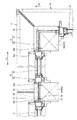
2階外壁部12は、階間梁(第2梁部材)25aと屋根梁(第1梁部材)25bとの間において上下方向に延びる複数の柱24を含む。本実施の形態では、図2に示されるように、各柱24は、下側壁体部21が固定される下側柱241と、上側壁体部22が固定される上側柱242とに分割されており、これらの柱241,242間に中間梁(第3梁部材)26が配置されている。柱241,242、および、梁25a,25b,26は、四角柱形状である。 The second floor outer wall portion 12 includes a plurality of columns 24 extending in the vertical direction between the interstitial beam (second beam member) 25a and the roof beam (first beam member) 25b. In the present embodiment, as shown in FIG. 2, each pillar 24 is divided into a lower pillar 241 to which the lower side wall body portion 21 is fixed and an upper pillar 242 to which the upper side wall body portion 22 is fixed. An intermediate beam (third beam member) 26 is arranged between these columns 241,242. The columns 241,242 and the beams 25a, 25b, 26 have a square column shape.

下側壁体部21は、柱24(241)よりも屋外側に配置されている。下側壁体部21は、柱24の屋外面(屋外側の面)に沿って配置される断熱材32と、屋外空間に面する外装面部材31と、外装面部材31および断熱材32の間に設けられた通気層33とを含む。 The lower side wall body portion 21 is arranged on the outdoor side of the pillar 24 (241). The lower side wall body portion 21 is between the heat insulating material 32 arranged along the outdoor surface (outdoor side surface) of the pillar 24, the exterior surface member 31 facing the outdoor space, and the exterior surface member 31 and the heat insulating material 32. Includes a ventilation layer 33 provided in.

断熱材32は比較的厚みが大きく、その厚み寸法D1は、たとえば90mmである。この場合、柱24の屋外面24aから外装面部材31の表面までの突出寸法、すなわち下側壁体部21の厚み寸法D2は、たとえば120mm以上である。なお、下側壁体部21の厚み寸法には、後述の下地合板36の厚みが含まれなくてもよい。 The heat insulating material 32 has a relatively large thickness, and its thickness dimension D1 is, for example, 90 mm. In this case, the protruding dimension from the outdoor surface 24a of the pillar 24 to the surface of the exterior surface member 31, that is, the thickness dimension D2 of the lower side wall body portion 21 is, for example, 120 mm or more. The thickness dimension of the lower side wall body portion 21 does not have to include the thickness of the base plywood 36 described later.

外装面部材31は、たとえばサイディング材である。外装面部材31の表面は、たとえば、柄を排除し、漆喰調の素材で形成されている。また、外装面部材31の表面の色は、白色系である。 The exterior surface member 31 is, for example, a siding material. The surface of the exterior surface member 31 is made of a plaster-like material, for example, excluding the handle. The surface color of the exterior surface member 31 is white.

柱24(241)の屋内側には、2階の室内空間80に面する内装面部材35が配置されている。また、横幅方向において隣り合う柱24間にも、断熱材39が設けられていてもよい。 On the indoor side of the pillar 24 (241), an interior surface member 35 facing the indoor space 80 on the second floor is arranged. Further, the heat insulating material 39 may be provided between the columns 24 adjacent to each other in the width direction.

図2を参照して、窓部41の高さ寸法(つまり、窓部41の下端位置から天井82までの高さ寸法)L1は、室内空間80に面する内装面部材35の高さ寸法(つまり、床81から窓部41の下端位置までの高さ寸法)L2の1/2以下である。外観上において、窓部41の高さ寸法L1は、2階外壁部12全体の高さ寸法(たとえば2600mm程度)の1/3以下であることが望ましい。具体的には、窓部41の高さ寸法L1は、500mm以上800mm以下である。 With reference to FIG. 2, the height dimension of the window portion 41 (that is, the height dimension from the lower end position of the window portion 41 to the ceiling 82) L1 is the height dimension of the interior surface member 35 facing the indoor space 80 (that is, the height dimension of the interior surface member 35 facing the indoor space 80). That is, the height dimension from the floor 81 to the lower end position of the window portion 41) is 1/2 or less of L2. In terms of appearance, it is desirable that the height dimension L1 of the window portion 41 is 1/3 or less of the height dimension (for example, about 2600 mm) of the entire second floor outer wall portion 12. Specifically, the height dimension L1 of the window portion 41 is 500 mm or more and 800 mm or less.

なお、1階外壁部11の断面構造も、下側壁体部21と同じである。また、図7に示すように、側方外壁部92(91)の断面構造も、窓部41e(41d)の部分を除いて、下側壁体部21と同じである。図7には、通気層33内に設けられた胴縁34が示されて
いる。
The cross-sectional structure of the first floor outer wall portion 11 is also the same as that of the lower side wall body portion 21. Further, as shown in FIG. 7, the cross-sectional structure of the lateral outer wall portion 92 (91) is the same as that of the lower side wall body portion 21 except for the portion of the window portion 41e (41d). FIG. 7 shows a furring strip 34 provided in the ventilation layer 33.

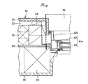
上側壁体部22は、柱24(242)間に固定された窓部41と、窓部41の側端部に隣接する柱被覆部44とを含む。柱被覆部44は、柱24ごとに設けられる。上側壁体部22は、上述の外装面部材31、断熱材32、および通気層33を含まない。また、柱242の外側面のうち屋内側の面は、室内空間80に露出していてもよい。 The upper side wall body portion 22 includes a window portion 41 fixed between columns 24 (242) and a column covering portion 44 adjacent to a side end portion of the window portion 41. The pillar covering portion 44 is provided for each pillar 24. The upper side wall body portion 22 does not include the exterior surface member 31, the heat insulating material 32, and the ventilation layer 33 described above. Further, the indoor side surface of the outer surface of the pillar 242 may be exposed to the indoor space 80.

上側壁体部22の各窓部41(41a〜41c)は、互いに隣り合う柱24間に嵌め入れられたサッシ(窓枠)42と、サッシ42内に嵌め込まれた透光性を有する板状のガラス窓43とで構成される。窓部41のガラス窓43の屋外面(表面)と柱被覆部44の屋外面(表面)とが、上側壁体部22の表面を構成する。 Each window portion 41 (41a to 41c) of the upper side wall body portion 22 has a sash (window frame) 42 fitted between columns 24 adjacent to each other and a plate shape having translucency fitted in the sash 42. It is composed of a glass window 43 of the above. The outdoor surface (surface) of the glass window 43 of the window portion 41 and the outdoor surface (surface) of the pillar covering portion 44 form the surface of the upper side wall body portion 22.

なお、窓部41は、典型的には、ガラス窓43を開閉できないフィックス窓タイプである。これにより、外観において、上側壁体部22をスッキリと見せることができる。 The window portion 41 is typically a fixed window type in which the glass window 43 cannot be opened and closed. As a result, the upper side wall body portion 22 can be made to look neat in appearance.

窓部41は、内外方向において、柱24の屋外面24aの位置を跨ぐように配置されている。また、窓部41の外方端は、下側壁体部21における断熱材32の厚み範囲内に位置している。つまり、窓部41は、少なくとも、下側壁体部21の通気層33よりも屋内側に位置している。より具体的には、窓部41の外方端は、断熱材32の厚み方向中央位置よりも屋内側に位置していることが望ましい。窓部41のうちガラス窓43の表面は、柱24の屋外面より僅かに屋外方向に位置しているのみである。ガラス窓43の表面は、柱24の屋外面よりも屋内側に位置していてもよい。 The window portion 41 is arranged so as to straddle the position of the outdoor surface 24a of the pillar 24 in the inward and outward directions. Further, the outer end of the window portion 41 is located within the thickness range of the heat insulating material 32 in the lower side wall body portion 21. That is, the window portion 41 is located at least on the indoor side of the ventilation layer 33 of the lower side wall body portion 21. More specifically, it is desirable that the outer end of the window portion 41 is located indoors rather than the central position in the thickness direction of the heat insulating material 32. The surface of the glass window 43 of the window portion 41 is located only slightly in the outdoor direction from the outdoor surface of the pillar 24. The surface of the glass window 43 may be located on the indoor side of the outdoor surface of the pillar 24.

図5に示すように、各窓部41には、サッシ42の上端部から上方に突出する取付け片42bと、サッシ42の下端部から下方に突出する取付け片42cとがさらに設けられている。取付け片42bは、屋根梁25b下の窓まぐさ(窓用横材)27に直接または間接的に固定される。取付け片42cは、中間梁26に直接または間接的に固定される。 As shown in FIG. 5, each window portion 41 is further provided with a mounting piece 42b projecting upward from the upper end portion of the sash 42 and a mounting piece 42c projecting downward from the lower end portion of the sash 42. The mounting piece 42b is directly or indirectly fixed to the window lintel (window cross member) 27 under the roof beam 25b. The mounting piece 42c is directly or indirectly fixed to the intermediate beam 26.

サッシ42は、屋外方向に突出する突出枠42aを有していてもよい。突出枠42aは、サッシ42の外縁部分に設けられる。突出枠42aの外方端の位置も、断熱材32の厚み範囲内に位置していることが望ましい。これにより、下側壁体部21の厚みと、インセット窓とを強調することができる。 The sash 42 may have a protruding frame 42a that projects in the outdoor direction. The protruding frame 42a is provided on the outer edge portion of the sash 42. It is desirable that the position of the outer end of the projecting frame 42a is also within the thickness range of the heat insulating material 32. Thereby, the thickness of the lower side wall body portion 21 and the inset window can be emphasized.

図1および図6に示されるように、柱被覆部44は、柱24の屋外面を覆うように配置されている。柱被覆部44と柱24との間には、下地合板45および胴縁46が介在している。下地合板45は、柱24の屋外面に面接触している。各窓部41には、サッシ42の両側部から側方に突出する取付け片42d,42eが設けられており、取付け片42d,42eが、この下地合板45を介して柱24に固定されている。柱被覆部44と下地合板45との間には、胴縁46の厚み分だけ通気空間47が形成されている。 As shown in FIGS. 1 and 6, the column covering portion 44 is arranged so as to cover the outdoor surface of the column 24. A base plywood 45 and a furring strip 46 are interposed between the pillar covering portion 44 and the pillar 24. The base plywood 45 is in surface contact with the outdoor surface of the pillar 24. Each window 41 is provided with mounting pieces 42d, 42e protruding laterally from both sides of the sash 42, and the mounting pieces 42d, 42e are fixed to the pillar 24 via the base plywood 45. .. A ventilation space 47 is formed between the column covering portion 44 and the base plywood 45 by the thickness of the furring strip 46.

柱被覆部44は、たとえばモールなどの装飾材によって構成される。柱被覆部44の屋外面(表面)の位置もまた、下側壁体部21における断熱材32の厚み範囲内に位置し、より具体的には、断熱材32の厚み方向中央位置よりも屋内側に位置する。 The pillar covering portion 44 is made of a decorative material such as a molding. The position of the outdoor surface (surface) of the column covering portion 44 is also located within the thickness range of the heat insulating material 32 in the lower side wall body portion 21, and more specifically, the indoor side of the central position of the heat insulating material 32 in the thickness direction. Located in.

窓部41および柱被覆部44の表面が、下側壁体部21の表面よりも後退した位置に配置されることで、下側壁体部21の壁厚を強調することができる。具体的には、外張りの断熱材32の厚みが通常よりも大きく、建物1の断熱性能の良さを外観において示すことができる。 By arranging the surfaces of the window portion 41 and the column covering portion 44 at positions recessed from the surface of the lower side wall body portion 21, the wall thickness of the lower side wall body portion 21 can be emphasized. Specifically, the thickness of the outer heat insulating material 32 is larger than usual, and the good heat insulating performance of the building 1 can be shown in appearance.

また、図6に示されるように、ガラス窓43の表面は、柱被覆部44の表面よりも屋内
側に位置している。これにより、ガラス窓43が、軸組としての柱24間に嵌め込まれているように見えるため、屋根14下のインセット窓を強調することができる。
Further, as shown in FIG. 6, the surface of the glass window 43 is located on the indoor side of the surface of the column covering portion 44. As a result, the glass window 43 appears to be fitted between the columns 24 as a framework, so that the inset window under the roof 14 can be emphasized.

また、柱被覆部44および窓部41のサッシ42の色は、下側壁体部21および1階外壁部11の表面の色よりも濃い色(たとえば茶系、黒系、紺系)である。これにより、屋根14の浮遊感がより一層高められる。また、柱被覆部44および窓部41のサッシ42(突出枠42aを含む)の表面を、木質の材料で形成することで、建物1の木軸を表現することができる。 The color of the sash 42 of the column covering portion 44 and the window portion 41 is darker than the surface colors of the lower side wall body portion 21 and the first floor outer wall portion 11 (for example, brown, black, and dark blue). As a result, the floating feeling of the roof 14 is further enhanced. Further, by forming the surfaces of the sash 42 (including the protruding frame 42a) of the pillar covering portion 44 and the window portion 41 with a wood-based material, the wooden axis of the building 1 can be expressed.

ここで、本実施の形態においては、上側壁体部22の表面が下側壁体部21の通気層33よりも屋内側に配置されるため、下側壁体部21の通気層33は上側壁体部22との境界部において途切れる。そのため、通気層33内の空気を、屋根14の軒裏空間16に到達させることができない。 Here, in the present embodiment, since the surface of the upper side wall body portion 22 is arranged on the indoor side of the ventilation layer 33 of the lower side wall body portion 21, the ventilation layer 33 of the lower side wall body portion 21 is the upper side wall body. It is interrupted at the boundary with the portion 22. Therefore, the air in the ventilation layer 33 cannot reach the eaves back space 16 of the roof 14.

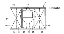
図16には、公知の建物100における外壁部110の構造とその通気経路とが模式的に示されている。外壁部110には窓が全くないか、外壁部110の横幅方向の一部分にしか窓がないものとする。外壁部110は、建物1の2階外壁部12における下側壁体部21と同様に、外装面部材131、断熱材132、および通気層133を含む。また、柱24の屋内面には内装面部材135が配置され、横幅方向において隣り合う柱24間に断熱材139が設けられている。 FIG. 16 schematically shows the structure of the outer wall portion 110 and the ventilation path thereof in the known building 100. It is assumed that the outer wall portion 110 has no window or only a part of the outer wall portion 110 in the lateral width direction has a window. The outer wall portion 110 includes an exterior surface member 131, a heat insulating material 132, and a ventilation layer 133, similarly to the lower side wall body portion 21 in the second floor outer wall portion 12 of the building 1. Further, an interior surface member 135 is arranged on the indoor surface of the pillar 24, and a heat insulating material 139 is provided between the adjacent pillars 24 in the lateral width direction.

建物100では、階間梁(図示せず)と屋根梁25bとの間に、中間梁26は存在しない。また、断熱材132の厚み寸法D3は、本実施の形態の断熱材32の厚み寸法D1より小さく、たとえば30mm(厚み寸法D1の1/3程度)である。 In the building 100, the intermediate beam 26 does not exist between the interstitial beam (not shown) and the roof beam 25b. Further, the thickness dimension D3 of the heat insulating material 132 is smaller than the thickness dimension D1 of the heat insulating material 32 of the present embodiment, for example, 30 mm (about 1/3 of the thickness dimension D1).

外装面部材131は、軒天井15と交差している。建物100においては、通気層133の上端部が軒裏空間16に向けて開放されているため、通気層133内の空気は、軒天通気口15aから適切に排気される。 The exterior surface member 131 intersects the eaves ceiling 15. In the building 100, since the upper end of the ventilation layer 133 is open toward the eaves back space 16, the air in the ventilation layer 133 is appropriately exhausted from the eaves ceiling ventilation port 15a.

これに対し、本実施の形態では、上述のように、下側壁体部21の通気層33は、軒裏空間16に連通されていない。その代わりに、下側壁体部21と上側壁体部22との間に設けられた水切部材23によって、通気層33内の空気が屋外空間に導かれる。 On the other hand, in the present embodiment, as described above, the ventilation layer 33 of the lower side wall body portion 21 is not communicated with the eaves back space 16. Instead, the air in the ventilation layer 33 is guided to the outdoor space by the drainage member 23 provided between the lower side wall body portion 21 and the upper side wall body portion 22.

(水切部材の構成および配置例について)
図5および図6を参照して、水切部材23の構成および配置例について説明する。
(About the configuration and arrangement example of the drainage member)
A configuration and an arrangement example of the drainage member 23 will be described with reference to FIGS. 5 and 6.

水切部材23は、下側壁体部21の上端部を覆うように、上側壁体部22の下端縁に沿って配置されている。なお、本実施の形態では、連窓40が平面視においてU字状に配置されているため、水切部材23もまた、平面視においてU字状に配置されている。 The drainage member 23 is arranged along the lower end edge of the upper side wall body portion 22 so as to cover the upper end portion of the lower side wall body portion 21. In the present embodiment, since the continuous windows 40 are arranged in a U shape in a plan view, the drainage member 23 is also arranged in a U shape in a plan view.

水切部材23の詳細な説明に先立ち、まず、水切部材23の周辺の構造について説明する。下側壁体部21の断熱材32の上部には、下地桟木37が設けられている。下地桟木37の全体の厚みは、断熱材32と略同じ厚みである。本実施の形態では、断熱材32と下地桟木37とで、通気層33の屋内側に位置する内側面部材を構成する。 Prior to the detailed explanation of the drainage member 23, first, the structure around the drainage member 23 will be described. A base lumber 37 is provided above the heat insulating material 32 of the lower side wall body portion 21. The total thickness of the base lumber 37 is substantially the same as that of the heat insulating material 32. In the present embodiment, the heat insulating material 32 and the base bar 37 form an inner side surface member located on the indoor side of the ventilation layer 33.

下地桟木37と中間梁26との間には、下地合板36が設けられている。窓部41の下方位置において、下地合板36の上端高さは、中間梁26の上端高さと略同じである。これに対し、柱被覆部44の下方位置においては、下地合板36は、図6に示した柱24に当接する下地合板45と一体的に設けられていてもよい。なお、柱24や中間梁26などの躯体部の屋外面に、下地合板36,45が存在しなくてもよい。 A base plywood 36 is provided between the base pier 37 and the intermediate beam 26. At the lower position of the window portion 41, the height of the upper end of the base plywood 36 is substantially the same as the height of the upper end of the intermediate beam 26. On the other hand, at the lower position of the pillar covering portion 44, the base plywood 36 may be provided integrally with the base plywood 45 that abuts on the pillar 24 shown in FIG. The base plywoods 36 and 45 may not be present on the outdoor surface of the skeleton such as the columns 24 and the intermediate beams 26.

下地桟木37の上端高さ、すなわち内側面部材の上端高さは、中間梁26の上端高さより低い。外装面部材31の上端高さも、中間梁26の上端高さより低いが、下地桟木37よりも若干高い。 The height of the upper end of the base pier 37, that is, the height of the upper end of the inner side surface member is lower than the height of the upper end of the intermediate beam 26. The height of the upper end of the exterior surface member 31 is also lower than the height of the upper end of the intermediate beam 26, but slightly higher than that of the base pier 37.

水切部材23は、下側壁体部21の上方において屋外方向(正面側)に向かって斜め下方に延びる被覆部51と、被覆部51の屋内側端部から上方に立ち上がる立上り部52と、被覆部51の屋外側端部から下方に垂れ下がる垂下部53とを含む。 The drainage member 23 includes a covering portion 51 extending diagonally downward toward the outdoor direction (front side) above the lower side wall body portion 21, a rising portion 52 rising upward from the indoor side end portion of the covering portion 51, and a covering portion. Includes a hanging portion 53 that hangs downward from the outdoor side end portion of 51.

水切部材23の被覆部51と外装面部材31の上端面との間には、隙間50が設けられている。この隙間50によって、下側壁体部21の通気層33と屋外空間とが連通される。 A gap 50 is provided between the covering portion 51 of the drainage member 23 and the upper end surface of the exterior surface member 31. The gap 50 communicates the ventilation layer 33 of the lower side wall body 21 with the outdoor space.

立上り部52は、中間梁26に、下地合板36を介してビス等により固定される。立上り部52は、窓部41の取付け片42c上に重ねられた状態で固定されている。 The rising portion 52 is fixed to the intermediate beam 26 with screws or the like via the base plywood 36. The rising portion 52 is fixed so as to be overlapped on the mounting piece 42c of the window portion 41.

垂下部53は、外装面部材31の表面から少し離れた位置に配置される。図5および図8に示されるように、外装面部材31と垂下部53との間に、所定間隔(たとえば500mmピッチ)で、水抜き具54が設けられている。水抜き具54としては、窓サッシに取り付ける部品として流通している部材を流用可能である。水抜き具54は、外装面部材31の表面に当接するように配置されている。 The hanging portion 53 is arranged at a position slightly away from the surface of the exterior surface member 31. As shown in FIGS. 5 and 8, drainage tools 54 are provided between the exterior surface member 31 and the hanging portion 53 at predetermined intervals (for example, at a pitch of 500 mm). As the drainage tool 54, a member distributed as a part to be attached to the window sash can be diverted. The drainage tool 54 is arranged so as to come into contact with the surface of the exterior surface member 31.

水抜き具54の周囲には、シーリング材55が設けられている。具体的には、シーリング材55は、湿式のシーリング材であり、水抜き具54と垂下部53との間、および、互いに隣り合う水抜き具54間に設けられる。各水抜き具54は、水抜き孔を有しており、この水抜き孔が、水切部材23の通気口23aとして機能する。 A sealing material 55 is provided around the drainage tool 54. Specifically, the sealing material 55 is a wet sealing material, and is provided between the draining tool 54 and the hanging portion 53, and between the draining tools 54 adjacent to each other. Each drainage tool 54 has a drainage hole, and the drainage hole functions as a vent 23a of the drainage member 23.

水切部材23の垂下部53と外装面部材31との間の隙間がこのように構成されることで、屋外空間から下側壁体部21の上部への雨水の吹き込み防止と、下側壁体部21の通気性確保との双方を実現することができる。 By forming the gap between the hanging portion 53 of the drainage member 23 and the exterior surface member 31 in this way, it is possible to prevent rainwater from being blown from the outdoor space to the upper part of the lower side wall body portion 21 and to prevent rainwater from blowing into the lower side wall body portion 21. It is possible to realize both the air permeability and the air permeability.

通気層33よりも屋内側に配置された部材は防水性が求められるため、断熱材32および下地桟木37の屋外面に、防水シート38aが設けられている。また、下地桟木37の上面と下地桟木37の屋外面とに、L字状に折られた防水シート38bが貼り付けられている。防水シート38bは、防水シート38aに重ねられる。これにより、何らかの原因で水切部材23の被覆部51の下に水が浸入してきたとしても、下地桟木37および断熱材32を防水することができる。 Since the member arranged indoors from the ventilation layer 33 is required to be waterproof, a waterproof sheet 38a is provided on the outdoor surface of the heat insulating material 32 and the base pier 37. Further, an L-shaped folded waterproof sheet 38b is attached to the upper surface of the base pier 37 and the outdoor surface of the base pier 37. The waterproof sheet 38b is superposed on the waterproof sheet 38a. As a result, even if water infiltrates under the covering portion 51 of the draining member 23 for some reason, the base lumber 37 and the heat insulating material 32 can be waterproofed.

上述のように、通気層33は、隙間50(および通気口23a)を介して屋外空間と連通する。そのため、2階外壁部12の上部に、その全幅に亘ってインセットされた連窓40を設けた場合であっても、通気層33内の空気の通気経路を確保することができる。したがって、下側壁体部21の劣化を抑制することができる。 As described above, the ventilation layer 33 communicates with the outdoor space through the gap 50 (and the ventilation port 23a). Therefore, even when the continuous window 40 inset over the entire width is provided on the upper part of the second floor outer wall portion 12, the air ventilation path in the ventilation layer 33 can be secured. Therefore, deterioration of the lower side wall body portion 21 can be suppressed.

なお、本実施の形態においては、図6に示されるように、柱被覆部44と柱24との間に通気空間47が設けられている。通気空間47には、柱被覆部44の下端部と水切部材23の被覆部51の上面との間の隙間から、屋外の空気が取入れられる。柱被覆部44の下端部の隙間から通気空間47に取入れられた空気は、通気空間47内を上昇し、軒天通気口15aから排気されるように構成されている。 In the present embodiment, as shown in FIG. 6, a ventilation space 47 is provided between the pillar covering portion 44 and the pillar 24. Outdoor air is taken into the ventilation space 47 from the gap between the lower end of the column covering portion 44 and the upper surface of the covering portion 51 of the drainage member 23. The air taken into the ventilation space 47 through the gap at the lower end of the column covering portion 44 rises in the ventilation space 47 and is exhausted from the eaves ceiling vent 15a.

これにより、本実施の形態によれば、上側壁体部22の躯体部(上側柱242)の劣化
を抑制することもできる。通気空間47に面する下地合板45および取付け片42d,42eには、防水シート48が貼り付けられることが望ましい。
As a result, according to the present embodiment, deterioration of the skeleton portion (upper pillar 242) of the upper side wall body portion 22 can be suppressed. It is desirable that the waterproof sheet 48 is attached to the base plywood 45 and the mounting pieces 42d and 42e facing the ventilation space 47.

以上説明したように、本実施の形態の建物1によれば、軸組構造を複雑にすることなく、意匠性の向上と外壁部10の通気性の確保とを両立させることができる。 As described above, according to the building 1 of the present embodiment, it is possible to achieve both the improvement of the design and the securing of the air permeability of the outer wall portion 10 without complicating the frame structure.

さらに、本実施の形態では、2階外壁部12に中間梁26が設けられるため、下側壁体部21およびその支持体(躯体部)を、耐力壁として構成することができる。このことについて、図9〜図11を用いて説明する。 Further, in the present embodiment, since the intermediate beam 26 is provided on the second floor outer wall portion 12, the lower side wall body portion 21 and its support (body portion) can be configured as a bearing wall. This will be described with reference to FIGS. 9 to 11.

図9には、本実施の形態における2階外壁部12の躯体部の構成(軸組構造)が模式的に示されている。図10および図11には、それぞれ、比較例における特定階の外壁部110の躯体部の構成が模式的に示されている。図10および図11の外壁部110の基本構造は、図16に示した公知の建物100の外壁部110と同じであると仮定する。図9には、通気層33の空気の流れが、図10および図11には、通気層133の空気の流れが模式的に示されている。 FIG. 9 schematically shows the configuration (framework structure) of the skeleton portion of the second floor outer wall portion 12 in the present embodiment. 10 and 11, respectively, schematically show the configuration of the skeleton portion of the outer wall portion 110 of the specific floor in the comparative example. It is assumed that the basic structure of the outer wall portion 110 of FIGS. 10 and 11 is the same as the outer wall portion 110 of the known building 100 shown in FIG. FIG. 9 schematically shows the air flow of the ventilation layer 33, and FIGS. 10 and 11 schematically show the air flow of the ventilation layer 133.

一般的には、図10に示されるように、窓部141は非耐力壁95に設けられる。そのため、外壁部110の少なくとも一部を耐力壁94としたい場合、窓部141は外壁部110の横幅方向における一部分にしか設けることができない。すなわち、図11に示されるように、外壁部110の全幅に亘り連窓40を設ける場合、通常は、外壁部110の全てが非耐力壁95として構成される。耐力壁94は、一対の梁25a,25bと一対の柱24とで構成される枠体に、筋交などの耐力要素940を有している。 Generally, as shown in FIG. 10, the window portion 141 is provided on the non-bearing wall 95. Therefore, when it is desired to use at least a part of the outer wall portion 110 as the bearing wall 94, the window portion 141 can be provided only on a part of the outer wall portion 110 in the lateral width direction. That is, as shown in FIG. 11, when the continuous window 40 is provided over the entire width of the outer wall portion 110, all of the outer wall portion 110 is usually configured as a non-bearing wall 95. The load-bearing wall 94 has a load-bearing element 940 such as a brace in a frame composed of a pair of beams 25a and 25b and a pair of columns 24.

これに対し、本実施の形態では、連窓40は、中間梁26と屋根梁25bとの間に配置されるため、下側壁体部21およびその支持体の全体または一部を、自由に、耐力壁94とすることができる。その結果、建物1によれば、外壁部10の躯体部の強度を向上させることも可能となる。なお、図9に示す耐力壁94は、図10に示すような通常の耐力壁94よりも高さが低いため、「腰壁耐力壁」と称してもよい。 On the other hand, in the present embodiment, since the continuous window 40 is arranged between the intermediate beam 26 and the roof beam 25b, the lower side wall body portion 21 and the whole or a part of the support thereof can be freely used. It can be a bearing wall 94. As a result, according to the building 1, it is possible to improve the strength of the skeleton portion of the outer wall portion 10. Since the bearing wall 94 shown in FIG. 9 is lower in height than the normal bearing wall 94 as shown in FIG. 10, it may be referred to as a “waist wall bearing wall”.

(連窓の他の配置例について)
連窓40の他の配置例を、図12および図13に示す。
(About other arrangement examples of continuous windows)
Other arrangement examples of the continuous window 40 are shown in FIGS. 12 and 13.

図12に示されるように、連窓40は、正面側の外壁部10(上側壁体部22)にのみ配置されていてもよい。つまり、図3に示したように、側方外壁部91,92に、正面側のコーナーの窓部41に隣接する側方窓部41d,41eが設けられていなくてもよい。あるいは、連窓40が平面視においてL字状となるように、側方外壁部91,92のうちの一方にのみ、側方窓部が設けられていてもよい。 As shown in FIG. 12, the continuous window 40 may be arranged only on the outer wall portion 10 (upper side wall body portion 22) on the front side. That is, as shown in FIG. 3, the side outer wall portions 91 and 92 may not be provided with the side window portions 41d and 41e adjacent to the window portion 41 in the front corner. Alternatively, the side window portion may be provided only on one of the side outer wall portions 91 and 92 so that the continuous window 40 has an L shape in a plan view.

また、図13に示されるように、正面側の外壁部10に位置する連窓40は、外壁部10の全幅に亘り設けられていなくてもよい。つまり、外壁部10において、連窓40の側方位置には、下側壁体部21と同じ構造の壁体部22Aが、下側壁体部21と連続的に配置されていてもよい。なお、この場合、壁体部22A内の通気層33は、軒裏空間16に連通する。 Further, as shown in FIG. 13, the continuous window 40 located on the outer wall portion 10 on the front side does not have to be provided over the entire width of the outer wall portion 10. That is, in the outer wall portion 10, the wall body portion 22A having the same structure as the lower side wall body portion 21 may be continuously arranged with the lower side wall body portion 21 at the lateral position of the continuous window 40. In this case, the ventilation layer 33 in the wall body portion 22A communicates with the eaves back space 16.

(変形例)
本実施の形態では、建物1の屋根14が、最上階の上に位置する勾配屋根であることとしたが、下屋を有する建物においても、上述の2階外壁部12の構造を適用可能である。
(Modification example)
In the present embodiment, the roof 14 of the building 1 is a sloped roof located on the top floor, but the above-mentioned structure of the outer wall portion 12 on the second floor can also be applied to a building having a lower house. be.

図14には、本実施の形態の変形例に係る建物1Aの構成例が模式的に示されている。
図14を参照して、建物1Aは、最上階(2階)の屋根14aと、1階の室内空間の上方に位置する下屋14bとを備えている。下屋14bは、2階外壁部12Aの下端部から正面方向に突出する片流れ屋根(勾配屋根)であり、その軒天井15が、1階外壁部11Aの上端に交差している。
FIG. 14 schematically shows a configuration example of the building 1A according to the modified example of the present embodiment.
With reference to FIG. 14, the building 1A includes a roof 14a on the top floor (second floor) and a lower house 14b located above the indoor space on the first floor. The lower house 14b is a one-sided roof (sloping roof) protruding in the front direction from the lower end of the second floor outer wall portion 12A, and the eaves ceiling 15 intersects the upper end of the first floor outer wall portion 11A.

この場合、下屋14b下の1階外壁部11Aが、上述の下側壁体部21と上側壁体部22とで構成されていてもよい。 In this case, the first floor outer wall portion 11A under the lower house 14b may be composed of the lower side wall body portion 21 and the upper side wall body portion 22 described above.

<実施の形態2>
上記実施の形態1に係る建物は、平面視において略矩形形状のシンプルな形状であり、正面外壁は、上述の外壁部10のみによって構成されているとして説明した。これに対し、本実施の形態に係る建物の正面外壁は、上述の外壁部10の他に、外壁部10の側方側に位置する他の外壁部を有している。
<Embodiment 2>
It has been described that the building according to the first embodiment has a simple shape having a substantially rectangular shape in a plan view, and the front outer wall is composed of only the above-mentioned outer wall portion 10. On the other hand, the front outer wall of the building according to the present embodiment has, in addition to the above-mentioned outer wall portion 10, another outer wall portion located on the side side of the outer wall portion 10.

図15は、実施の形態2に係る住宅の正面側の外観図である。住宅は、建物1Bとその前方(正面方向)に位置する外構部4とを含む。 FIG. 15 is an external view of the front side of the house according to the second embodiment. The house includes the building 1B and the exterior part 4 located in front of the building 1B (in the front direction).

建物1Bは、外観上、横幅方向において互いに隣接する第1の箱体2と第2の箱体3とで構成されている。第1の箱体2は、実施の形態1で示した建物1と同様に、外壁部10と側方外壁部91,92とを有している。第2の箱体3の高さは、第1の箱体2と同じ高さである。 The building 1B is composed of a first box body 2 and a second box body 3 that are adjacent to each other in the width direction in appearance. The first box body 2 has an outer wall portion 10 and lateral outer wall portions 91 and 92, similarly to the building 1 shown in the first embodiment. The height of the second box body 3 is the same as the height of the first box body 2.

第2の箱体3は、正面側に外壁部60を有している。本実施の形態では、第1の箱体2の紙面右側の側方外壁部92の横幅が、紙面左側の側方外壁部91の横幅よりも短く、外壁部60は、第1の箱体2の側方外壁部92と交差している。 The second box body 3 has an outer wall portion 60 on the front side. In the present embodiment, the width of the lateral outer wall portion 92 on the right side of the paper surface of the first box body 2 is shorter than the width of the side outer wall portion 91 on the left side of the paper surface, and the outer wall portion 60 is the first box body 2. It intersects with the lateral outer wall portion 92 of.

このように、建物1Bの正面外壁は、外壁部10と、外壁部10よりも奥側(後退した位置)に配置された外壁部60とで構成されている。外壁部60の前方(正面方向)かつ第1の箱体2の側方外壁部92の側方に位置する空間に、庭が形成されている。 As described above, the front outer wall of the building 1B is composed of the outer wall portion 10 and the outer wall portion 60 arranged on the back side (retracted position) of the outer wall portion 10. A garden is formed in a space located in front of the outer wall portion 60 (in the front direction) and on the side of the lateral outer wall portion 92 of the first box body 2.

第2の箱体3の屋根63も、正面方向に向かって傾斜する勾配屋根である。そのため、屋根63は、外壁部60の上端と交差する軒天井64を有している。第2の箱体3の屋根63は、第1の箱体2の屋根14と繋がっている。 The roof 63 of the second box 3 is also a sloped roof that inclines toward the front. Therefore, the roof 63 has an eaves ceiling 64 that intersects the upper end of the outer wall portion 60. The roof 63 of the second box body 3 is connected to the roof 14 of the first box body 2.

第2の箱体3の外壁部60の2階部分には、略全面に窓が設けられた壁部61と、インナーバルコニー65に面する壁部62とが設けられている。壁部61は、第1の箱体2の側方外壁部92に交差する。インナーバルコニー65は、壁部61の側方に位置しており、インナーバルコニー65の前端部には、上方に立ち上がる立壁部66が設けられている。立壁部66の表面は、外壁部10の外壁面(外装面部材31の表面)と同じ素材および色調で形成されている。 On the second floor portion of the outer wall portion 60 of the second box body 3, a wall portion 61 having a window provided on substantially the entire surface and a wall portion 62 facing the inner balcony 65 are provided. The wall portion 61 intersects the lateral outer wall portion 92 of the first box body 2. The inner balcony 65 is located on the side of the wall portion 61, and a standing wall portion 66 that rises upward is provided at the front end portion of the inner balcony 65. The surface of the vertical wall portion 66 is formed of the same material and color as the outer wall surface of the outer wall portion 10 (the surface of the exterior surface member 31).

ここで、立壁部66の高さ寸法は、一般的なバルコニー用腰壁よりも高い。具体的には、立壁部66とその上の軒天井(バルコニー天井)64との間の間隔(鉛直方向の距離)L4は、第1の箱体2の上側壁体部22(すなわち連窓40)の高さ寸法L3と略同一である。ここでの略同一とは、両者の寸法の差が100mm以下であればよく、50mm以下であることが望ましい。 Here, the height dimension of the standing wall portion 66 is higher than that of a general waist wall for balconies. Specifically, the distance (vertical distance) L4 between the vertical wall portion 66 and the eaves ceiling (balcony ceiling) 64 above it is the upper side wall body portion 22 (that is, the continuous window 40) of the first box body 2. ) Is substantially the same as the height dimension L3. The term “substantially the same” here means that the difference in dimensions between the two is 100 mm or less, and preferably 50 mm or less.

このように、住宅の建物1Bを正面側から見た場合、勾配屋根14,63の下に、2つのスリットが設けられたような印象を与えることができる。そのため、建物1B全体として屋根14,63の浮遊感を演出することができる。 In this way, when the residential building 1B is viewed from the front side, it is possible to give the impression that two slits are provided under the sloped roofs 14 and 63. Therefore, it is possible to produce a floating feeling of the roofs 14 and 63 as the entire building 1B.

さらに、本実施の形態では、建物1Bの前方に、屋根76付きの外構部4が配置されている。屋根76もまた、勾配屋根であり、典型的には、正面方向に傾斜する片流れ屋根である。 Further, in the present embodiment, the exterior portion 4 with the roof 76 is arranged in front of the building 1B. The roof 76 is also a sloping roof, typically a one-way roof sloping in the front direction.

外構部4は、屋根76の下に、外構壁71とガレージ72とを有している。外構壁71とガレージ72とは横幅方向において互いに離れて配置されている。外構壁71は、外壁部10と略平行に配置されている。外構壁71は、たとえば天然石壁で構成されている。 The exterior portion 4 has an exterior wall 71 and a garage 72 under the roof 76. The exterior wall 71 and the garage 72 are arranged apart from each other in the lateral width direction. The outer wall 71 is arranged substantially parallel to the outer wall portion 10. The exterior wall 71 is made of, for example, a natural stone wall.

ガレージ72は、屋根76の下面を構成する天井部(以下「外構天井」という)77と接しているのに対し、外構壁71は、外構天井77から離れている。外構壁71の上の外構天井77は、外構壁71の奥に配置された支持部材73,74によって下方から支持されている。支持部材73,74は、袖壁であってもよいし、柱であってもよい。 The garage 72 is in contact with the ceiling portion (hereinafter referred to as “exterior ceiling”) 77 constituting the lower surface of the roof 76, while the exterior wall 71 is separated from the exterior ceiling 77. The exterior ceiling 77 above the exterior wall 71 is supported from below by support members 73 and 74 arranged behind the exterior wall 71. The support members 73 and 74 may be sleeve walls or pillars.

このように、図15に示す住宅は、外構壁71と外構天井77との間にも、横幅方向に延びるスリットが設けられたような外観構成となっている。したがって、建物1Bと外構部4とに統一感が生じる。その結果、建物1Bと外構部4とを含めた住宅全体の意匠性を向上させることができる。 As described above, the house shown in FIG. 15 has an external configuration in which a slit extending in the width direction is also provided between the exterior wall 71 and the exterior ceiling 77. Therefore, a sense of unity is created between the building 1B and the exterior portion 4. As a result, the design of the entire house including the building 1B and the exterior part 4 can be improved.

また、存在感のある外構部4の屋根76は、建物1Bから独立して設けられているため、外構部4の高さを抑えることができる。また、全ての屋根14a,14b,76をなだらかな勾配の瓦屋根としている。したがって、本実施の形態の住宅によれば、日本の風景と調和する、奥行きと品格のある街並みを造り出すことができる。 Further, since the roof 76 of the exterior portion 4 having a strong presence is provided independently of the building 1B, the height of the exterior portion 4 can be suppressed. In addition, all roofs 14a, 14b, and 76 are tiled roofs with a gentle slope. Therefore, according to the housing of the present embodiment, it is possible to create a cityscape with depth and dignity that is in harmony with the Japanese landscape.

また、支持部材73,74のうち、外構部4の中央寄りの支持部材74と、ガレージ72との間には、縦格子75が設けられている。これにより、外部から住宅の庭への視線、および、庭に面した窓への視線(つまり、その奥の居住空間への視線)を適度に抑制することができる。したがって、意匠性を害することなく、プライバシー性を向上させることができる。 Further, among the support members 73 and 74, a vertical grid 75 is provided between the support member 74 near the center of the outer structure portion 4 and the garage 72. As a result, the line of sight from the outside to the garden of the house and the line of sight to the window facing the garden (that is, the line of sight to the living space behind it) can be appropriately suppressed. Therefore, privacy can be improved without impairing the design.

なお、以上説明した各実施の形態では、建物1が2階建てであることとしたが、1階建であってもよいし、3階以上の建物であってもよい。いずれにしても、軒先に軒天井15を有する屋根の直下に位置する特定階の外壁部が、上述の下側壁体部21および上側壁体部22を含んでいればよい。 In each of the above-described embodiments, the building 1 is a double-decker building, but it may be a single-story building or a building with three or more floors. In any case, the outer wall portion of the specific floor located directly below the roof having the eaves ceiling 15 at the eaves may include the lower side wall body portion 21 and the upper side wall body portion 22 described above.

また、上側壁体部22が、連窓40により構成されることとしたが、限定的ではない。上側壁体部22の表面が、下側壁体部21の表面(外装面部材31の表面)より後退した位置に配置され、かつ、下側壁体部21の表面とは素材および色調の少なくとも一方が異なっていればよい。具体的には、上側壁体部22の表面の色調は、下側壁体部21の表面よりも暗いことが望ましい。 Further, the upper side wall body portion 22 is formed by the continuous window 40, but the present invention is not limited. The surface of the upper side wall body portion 22 is arranged at a position recessed from the surface of the lower side wall body portion 21 (the surface of the exterior surface member 31), and at least one of the material and the color tone of the surface of the lower side wall body portion 21 is It only has to be different. Specifically, it is desirable that the color tone of the surface of the upper side wall body portion 22 is darker than that of the surface of the lower side wall body portion 21.

また、下側壁体部21の内側面部材が、主に断熱材32により構成されることとしたが、限定的ではない。 Further, the inner side surface member of the lower side wall body portion 21 is mainly composed of the heat insulating material 32, but the present invention is not limited.

また、外壁部10が建物1(1A,1B)の正面側に配置されることとして説明したが、限定的ではない。また、建物1は、木造でなくてもよい。建物1は、住宅以外の建物に適用してもよい。 Further, although it has been described that the outer wall portion 10 is arranged on the front side of the building 1 (1A, 1B), the present invention is not limited. Further, the building 1 does not have to be made of wood. Building 1 may be applied to buildings other than houses.

今回開示された実施の形態はすべての点で例示であって制限的なものではないと考えられるべきである。本発明の範囲は上記した説明ではなくて特許請求の範囲によって示され
、特許請求の範囲と均等の意味および範囲内でのすべての変更が含まれることが意図される。
It should be considered that the embodiments disclosed this time are exemplary in all respects and not restrictive. The scope of the present invention is shown by the scope of claims rather than the above description, and it is intended to include all modifications within the meaning and scope equivalent to the scope of claims.

1,1A,1B,100 建物、2 第1の箱体、3 第2の箱体、4 外構部、10,60,110 (正面側の)外壁部、11,11A 1階外壁部、12,12A 2階外壁部、13 玄関扉、14,14a,14b,63,76 勾配屋根、15,64 軒天井、15a 軒天通気口、16 軒裏空間、21 下側壁体部、22 上側壁体部、23 水切部材、24,241,242 柱、25a,25b,26 梁(梁部材)、31,131 外装面部材、32,39,132,139 断熱材、33,133 通気層、34,46 胴縁、35,135 内装面部材、36,45 下地合板、37 下地桟木、38a,38b,48 防水シート、40,140 連窓、41,41a〜41e,141 窓部、42 サッシ、42a 突出枠、42b,42c,42d,42e 取付け片、43 ガラス窓、44 柱被覆部、47 通気空間、50 隙間、51 被覆部、52 立上り部、53 垂下部、54 水抜き具、55 シーリング材、61,62 壁部、65 インナーバルコニー、66 立壁部、71 外構壁、72 ガレージ、73,74,74 支持部材、75 縦格子、77 外構天井、80 室内空間、81 床、82 天井、91,92 側方外壁部、93 背面外壁部、94 耐力壁、95 非耐力壁、940 耐力要素。 1,1A, 1B, 100 Building, 2 1st box body, 3 2nd box body, 4 Exterior part, 10, 60, 110 (front side) outer wall part, 11, 11A 1st floor outer wall part, 12 , 12A 2nd floor outer wall, 13 entrance door, 14,14a, 14b, 63,76 sloped roof, 15,64 eaves ceiling, 15a eaves ceiling vent, 16 eaves back space, 21 lower side wall body, 22 upper side wall body Part, 23 drainage member, 24,241,242 pillar, 25a, 25b, 26 beam (beam member), 31,131 exterior surface member, 32,39,132,139 insulation material, 33,133 ventilation layer, 34,46 Furnace, 35,135 Interior surface members, 36,45 Base plywood, 37 Base crosspieces, 38a, 38b, 48 Waterproof sheets, 40,140 consecutive windows, 41,41a to 41e, 141 windows, 42 sashes, 42a protruding frames , 42b, 42c, 42d, 42e Mounting piece, 43 glass window, 44 pillar covering part, 47 ventilation space, 50 gap, 51 covering part, 52 rising part, 53 hanging part, 54 drainage tool, 55 ceiling material, 61, 62 Walls, 65 Inner balcony, 66 Standing walls, 71 Exterior walls, 72 Garages, 73,74,74 Support members, 75 Vertical grids, 77 Exterior ceilings, 80 Interior spaces, 81 floors, 82 ceilings, 91,92 Side outer wall, 93 back outer wall, 94 bearing wall, 95 non-bearing wall, 940 bearing element.

Claims (1)

屋根と、
前記屋根の下方に位置する特定階の外壁部とを備え、
前記外壁部は、前記屋根に交差する上側壁体部と、前記上側壁体部の下方に位置する下側壁体部とを含み、
前記上側壁体部の表面は、前記下側壁体部の表面よりも後退した位置に配置され、かつ、前記下側壁体部の表面とは素材および色調の少なくとも一方が異なっている、建物。
With the roof
It is equipped with an outer wall of a specific floor located below the roof.
The outer wall portion includes an upper side wall body portion that intersects the roof and a lower side wall body portion that is located below the upper side wall body portion.
A building in which the surface of the upper side wall body portion is arranged at a position recessed from the surface of the lower side wall body portion, and at least one of the material and the color tone is different from the surface of the lower side wall body portion.
JP2021111953A 2016-02-08 2021-07-06 building Active JP7248746B2 (en)

Priority Applications (1)

Application Number Priority Date Filing Date Title
JP2021111953A JP7248746B2 (en) 2016-02-08 2021-07-06 building

Applications Claiming Priority (2)

Application Number Priority Date Filing Date Title
JP2016021932A JP6910106B2 (en) 2016-02-08 2016-02-08 building
JP2021111953A JP7248746B2 (en) 2016-02-08 2021-07-06 building

Related Parent Applications (1)

Application Number Title Priority Date Filing Date
JP2016021932A Division JP6910106B2 (en) 2016-02-08 2016-02-08 building

Publications (2)

Publication Number Publication Date
JP2021167564A true JP2021167564A (en) 2021-10-21
JP7248746B2 JP7248746B2 (en) 2023-03-29

Family

ID=59627051

Family Applications (2)

Application Number Title Priority Date Filing Date
JP2016021932A Active JP6910106B2 (en) 2016-02-08 2016-02-08 building
JP2021111953A Active JP7248746B2 (en) 2016-02-08 2021-07-06 building

Family Applications Before (1)

Application Number Title Priority Date Filing Date
JP2016021932A Active JP6910106B2 (en) 2016-02-08 2016-02-08 building

Country Status (1)

Country Link
JP (2) JP6910106B2 (en)

Families Citing this family (1)

* Cited by examiner, † Cited by third party
Publication number Priority date Publication date Assignee Title
JP7259560B2 (en) * 2019-06-03 2023-04-18 積水ハウス株式会社 building

Citations (3)

* Cited by examiner, † Cited by third party
Publication number Priority date Publication date Assignee Title
JP2001193169A (en) * 1999-10-29 2001-07-17 Misawa Homes Co Ltd Outer wall structure of unit building
JP2005120786A (en) * 2003-10-20 2005-05-12 Tesuku:Kk Architrave structure in ventilating exterior wall
JP2009228252A (en) * 2008-03-21 2009-10-08 Ig Kogyo Kk Ventilation starter

Family Cites Families (4)

* Cited by examiner, † Cited by third party
Publication number Priority date Publication date Assignee Title
JP2003328571A (en) * 2002-05-14 2003-11-19 Misawa Homes Co Ltd Unit type building
JP4118303B2 (en) * 2006-03-08 2008-07-16 エス・バイ・エル株式会社 Ventilation method and apparatus for building walls
JP5873369B2 (en) * 2012-03-28 2016-03-01 トヨタホーム株式会社 Building overhang structure
JP6169387B2 (en) * 2013-03-27 2017-07-26 大和ハウス工業株式会社 Housing structure

Patent Citations (3)

* Cited by examiner, † Cited by third party
Publication number Priority date Publication date Assignee Title
JP2001193169A (en) * 1999-10-29 2001-07-17 Misawa Homes Co Ltd Outer wall structure of unit building
JP2005120786A (en) * 2003-10-20 2005-05-12 Tesuku:Kk Architrave structure in ventilating exterior wall
JP2009228252A (en) * 2008-03-21 2009-10-08 Ig Kogyo Kk Ventilation starter

Non-Patent Citations (1)

* Cited by examiner, † Cited by third party
Title
"〜創立90周年記念〜創業の地(京都市伏見区竹中町)にグループ社員の研修施設「宝ホールディングス歴史記", 宝ホールディングス株式会社ホームページ, JPN6020038219, 14 September 2015 (2015-09-14), ISSN: 0004854900 *

Also Published As

Publication number Publication date
JP7248746B2 (en) 2023-03-29
JP2017141563A (en) 2017-08-17
JP6910106B2 (en) 2021-07-28

Similar Documents

Publication Publication Date Title
JP6436130B2 (en) Residential
JP2021167564A (en) building
ITMI20140071U1 (en) WALL ELEMENT
JP6933904B2 (en) Housing
US20160002908A1 (en) Building and method for constructing such a building
JP5002239B2 (en) building
JP6638762B2 (en) Housing
JP5886778B2 (en) Unit building
JP2022026421A (en) Building structure
JP7272117B2 (en) Opening structure and building
JP6689021B2 (en) building
JP2008303570A (en) Building with balcony
JP6549998B2 (en) building
JP2019199786A (en) building
JP2014084586A (en) Dwelling house
JP5756069B2 (en) 庇 structure
JP2006077455A (en) Building
JP7165302B2 (en) housing
JP2017166270A (en) building
JP2017115522A (en) Housing
JP2017115523A (en) House
JP2003313955A (en) Unit building
JP4796403B2 (en) building
JP2017115524A (en) Housing
JP2022143932A (en) building

Legal Events

Date Code Title Description
A521 Request for written amendment filed

Free format text: JAPANESE INTERMEDIATE CODE: A523

Effective date: 20210728

A621 Written request for application examination

Free format text: JAPANESE INTERMEDIATE CODE: A621

Effective date: 20210728

A131 Notification of reasons for refusal

Free format text: JAPANESE INTERMEDIATE CODE: A131

Effective date: 20220823

A521 Request for written amendment filed

Free format text: JAPANESE INTERMEDIATE CODE: A523

Effective date: 20221021

TRDD Decision of grant or rejection written
A01 Written decision to grant a patent or to grant a registration (utility model)

Free format text: JAPANESE INTERMEDIATE CODE: A01

Effective date: 20230228

A61 First payment of annual fees (during grant procedure)

Free format text: JAPANESE INTERMEDIATE CODE: A61

Effective date: 20230316

R150 Certificate of patent or registration of utility model

Ref document number: 7248746

Country of ref document: JP

Free format text: JAPANESE INTERMEDIATE CODE: R150