JP5886778B2 - Unit building - Google Patents

Unit building Download PDF

Info

Publication number
JP5886778B2
JP5886778B2 JP2013048785A JP2013048785A JP5886778B2 JP 5886778 B2 JP5886778 B2 JP 5886778B2 JP 2013048785 A JP2013048785 A JP 2013048785A JP 2013048785 A JP2013048785 A JP 2013048785A JP 5886778 B2 JP5886778 B2 JP 5886778B2
Authority
JP
Japan
Prior art keywords
unit
building
roof
flat roof
floor
Prior art date
Legal status (The legal status is an assumption and is not a legal conclusion. Google has not performed a legal analysis and makes no representation as to the accuracy of the status listed.)
Expired - Fee Related
Application number
JP2013048785A
Other languages
Japanese (ja)
Other versions
JP2014134086A (en
Inventor
堀内 淳
淳 堀内
Current Assignee (The listed assignees may be inaccurate. Google has not performed a legal analysis and makes no representation or warranty as to the accuracy of the list.)
Misawa Homes Co Ltd
Original Assignee
Misawa Homes Co Ltd
Priority date (The priority date is an assumption and is not a legal conclusion. Google has not performed a legal analysis and makes no representation as to the accuracy of the date listed.)
Filing date
Publication date
Application filed by Misawa Homes Co Ltd filed Critical Misawa Homes Co Ltd
Priority to JP2013048785A priority Critical patent/JP5886778B2/en
Publication of JP2014134086A publication Critical patent/JP2014134086A/en
Application granted granted Critical
Publication of JP5886778B2 publication Critical patent/JP5886778B2/en
Expired - Fee Related legal-status Critical Current
Anticipated expiration legal-status Critical

Links

Images

Landscapes

  • Residential Or Office Buildings (AREA)

Description

本発明は、ユニット式建物に関する。   The present invention relates to a unit building.

従来から、予め工場で製造した建物ユニットや屋根ユニットを建築現場で組み合わせて形成されるユニット式建物が利用されている(例えば、特許文献1参照)。これら建物ユニットや屋根ユニットは平面寸法がモジュール化されており、1の建物ユニット上に1の屋根ユニットが載置されることにより、全体として構造上強固な建物が形成される。このようなユニット式建物によれば、建築現場における作業が軽減され、短期間で施工が完了するという利点がある。
かかる屋根ユニットは、上階を形成する建物ユニットの上部に載置されるベースパネルとしての小屋パネルと、当該小屋パネルの上面側に配置される複数の束と、これら各束を介して配設され、外観上の屋根面を構成する屋根パネルとを有している。また、屋根の形状としては、傾斜した屋根面を有する勾配屋根が多く採用されている。
Conventionally, a unit type building formed by combining a building unit and a roof unit manufactured in advance in a factory at a construction site has been used (for example, see Patent Document 1). These building units and roof units are modular in plan dimension, and by placing one roof unit on one building unit, a structurally strong building as a whole is formed. According to such a unit type building, there is an advantage that the work on the construction site is reduced and the construction is completed in a short period of time.
Such a roof unit is arranged via a shed panel as a base panel placed on top of a building unit forming an upper floor, a plurality of bundles arranged on the upper surface side of the shed panel, and each of these bundles And a roof panel constituting a roof surface in appearance. As the shape of the roof, a sloped roof having an inclined roof surface is often used.

一方、近年、都市部等の住宅密集地では土地が狭くなってきており、特許文献1のような勾配屋根を備えたユニット式建物による住宅では、当該勾配屋根の軒が建物本体外周よりも外方へ位置する分、建物本体(すなわち、居住空間)が狭くなることが懸念されている。
このため、狭い土地(敷地)に建てられる住宅では勾配屋根に替えて、軒をなくすことで居住空間を可能な限り広く確保でき、当該敷地を無駄なく有効活用することができる屋根面が略平坦な陸屋根を採用する傾向がある(例えば、特許文献2参照)。
このような陸屋根の形状をなす屋根ユニットは、小屋パネルの外周縁部にパラペットを配設し、当該パラペットの内側に緩勾配を有するように屋根材(防水シート等)を配設することで形成される。
On the other hand, in recent years, land has become narrower in densely populated areas such as urban areas, and in houses with unit type buildings with a sloped roof as in Patent Document 1, the eaves of the sloped roof are located outside the outer periphery of the building body. There is a concern that the building body (that is, the living space) will be narrowed as it is located in the direction.
For this reason, in a house built on a narrow land (site), instead of using a sloped roof, it is possible to secure as much space as possible by eliminating the eaves, and the roof surface that can effectively use the site without waste is almost flat. There is a tendency to adopt a flat roof (for example, refer to Patent Document 2).
The roof unit having the shape of such a flat roof is formed by disposing a parapet on the outer peripheral edge of the hut panel and disposing a roof material (such as a waterproof sheet) so as to have a gentle slope inside the parapet. Is done.

特開平03−217531号公報Japanese Patent Laid-Open No. 03-217531 特開2009−068222号公報JP 2009-068222 A

ところで、例えば二階建ての住宅を基準として、特許文献2のような陸屋根を備えた住宅と、勾配屋根を備えた住宅とを比較してみると、後者の方が前者よりも、建物本体の上部に配置される屋根ユニットにおいて屋根面が勾配し小屋裏空間が形成される分、建物全体としての高さが高くなる場合がある。すなわち、陸屋根の住宅では、例えば隣接する住宅が勾配屋根である場合、当該勾配屋根の住宅よりも建物全体の高さが低くなる虞があり、外観上、見映えに欠けることが懸念されている。   By the way, for example, based on a two-story house, when comparing a house with a flat roof as in Patent Document 2 and a house with a sloped roof, the latter is the upper part of the building body than the former. The height of the entire building may be increased by the amount of the roof surface being sloped and the hut space being formed in the roof unit disposed in the building. That is, in a flat roof house, for example, when the adjacent house is a sloped roof, the height of the entire building may be lower than that of the sloped roof house, and there is a concern that the appearance may be lacking in appearance. .

一方、近年における生活の質の向上や多様化に伴い、生活に使用する物品が多種多様化および多数化する傾向にある。しかし、これらの物品を保管、収容するための空間としては、従来のような建物内部の押入や納戸、小屋裏収納部や天井裏収納部等の小さな収納空間では広さや容量が不足してしまう。とりわけ、勾配屋根の小屋裏収納部は、天井高が勾配なりになってしまうため、物品の出し入れの際に屈まなければならず使い勝手が悪かった。また、建物が建てられる敷地の有効利用という観点から、屋外物置等の設置は望ましくないため、その内部に従来よりも大きな収納空間を備えた建物が望まれていた。   On the other hand, with the improvement and diversification of the quality of life in recent years, articles used for daily life tend to be diversified and increased in number. However, as a space for storing and storing these articles, there is a lack of space and capacity in a small storage space such as a conventional interior push-in or storage room, a shed storage section, or a ceiling storage section. . In particular, the shed storage section of the sloped roof has a ceiling height which makes it difficult to use because it has to bend in and out of goods. In addition, from the viewpoint of effective use of the site where the building is built, it is not desirable to install an outdoor storeroom or the like, and thus a building having a larger storage space than before has been desired.

しかしながら、特許文献2のような陸屋根を備えた住宅の場合、屋根面が平坦であることが外観上の特徴であると共に、屋根ユニットも共通化することで、製造コストの削減や、建築現場における作業の軽減および施工期間の短期化を図っていたことから、当該陸屋根の一部を嵩上げして、その下部に収納空間を形成するといった発想がなかった。これは、以下のようなことにも起因する。すなわち、このような屋根ユニットや建物ユニットによるユニット式の住宅の場合、陸屋根の一部を柱や梁などの構造耐力部材を用いて嵩上げすると、当該嵩上げ部分が最上階とみなされ、その最上部の梁の位置までが軒高として判断される可能性がある。この場合、建築基準法における日影規制等の制限をオーバーしてしまう虞がある。   However, in the case of a house with a flat roof as in Patent Document 2, a flat roof surface is a feature on the appearance, and by using a common roof unit, it is possible to reduce manufacturing costs and Since the work was reduced and the construction period was shortened, there was no idea of raising a part of the land roof and forming a storage space in the lower part thereof. This is also due to the following. That is, in the case of such a unit type house with a roof unit or a building unit, when a part of the land roof is raised using a structural load-bearing member such as a pillar or a beam, the raised part is regarded as the top floor, Up to the position of the beam may be judged as eave height. In this case, there is a risk of exceeding the restrictions such as shading regulations in the Building Standard Law.

従って、陸屋根を備えた住宅であっても、勾配屋根を備える建物よりも建物全体の高さが低くなることを確実に回避して外観の意匠性を向上できると共に、建物内部に必要上十分な収納空間を設けることができる技術の開発が望まれている。   Therefore, even if it is a house with a flat roof, it is possible to improve the design of the appearance by reliably avoiding the fact that the height of the whole building is lower than a building with a sloped roof, and it is necessary and sufficient for the interior of the building. Development of a technology capable of providing a storage space is desired.

そこで、本発明は上述した事情に鑑みてなされたもので、外観の意匠性を向上できると共に、建物内部に必要上十分な収納空間を設けることができる陸屋根を備えたユニット式建物を実現することを目的とする。   Therefore, the present invention has been made in view of the above-described circumstances, and realizes a unit type building having a flat roof that can improve the design of the appearance and can provide a necessary and sufficient storage space inside the building. With the goal.

請求項1に記載の発明は、例えば図1〜図10に示すように、垂直方向および水平方向に複数配置される建物ユニットUによって構築される建物本体Hと、前記建物本体Hの最上階を構成する前記複数の建物ユニットの上部のそれぞれに配置される複数の陸屋根ユニット50,60によって構築される屋根(陸屋根5および高屋根部6)と、を備えたユニット式建物において、
前記複数の陸屋根ユニットは、
規定寸法からなる通常の高さ寸法の第1陸屋根ユニット50と、
前記建物本体Hの最上階に位置する前記複数の建物ユニットUのうち、一部の前記建物ユニットUの上面に載置され、かつ前記第1陸屋根ユニット50に比べて高さ方向の寸法が嵩上げされてなる第2陸屋根ユニット60と、が含まれており、
前記第2陸屋根ユニット60は、
前記一部の建物ユニットUの長辺側に配置される一対の長辺梁61,61と、短辺側に配置される一対の短辺梁62,62と、を有して矩形枠状に形成され、かつ前記一部の建物ユニットUにおける上端部と略等しい大きさに設定された小屋パネル63と、
前記小屋パネル63の上面に立設される、二次部材である複数の束64…と、
前記複数の束64…の上端部に設けられる屋根パネル69と、
前記複数の束64…の外側に設けられる外壁材(外周壁3b)と、
前記複数の束64…に取り付けられる外壁受部65と、
前記外壁受部65に取り付けられ、前記屋根パネル69よりも上方に突出するパラペット部41を構成するためのパラペット用下地66と、を有し、
前記小屋パネル63と、前記外壁受部65と、前記パラペット用下地66とによって前記外壁材(外周壁3b)を受けることを特徴とする。
As shown in FIGS. 1 to 10, for example, the invention described in claim 1 includes a building body H constructed by a plurality of building units U arranged in the vertical direction and the horizontal direction, and the top floor of the building body H In a unit type building comprising: a roof (land roof 5 and high roof portion 6) constructed by a plurality of flat roof units 50, 60 disposed on top of each of the plurality of building units constituting
The plurality of flat roof units,
A first flat roof unit 50 having a normal height and a predetermined size;
Among the plurality of building units U located on the top floor of the building main body H, the size is raised on the upper surface of some of the building units U and the height direction is higher than that of the first flat roof unit 50. A second flat roof unit 60 formed, and
The second flat roof unit 60 is
A rectangular frame shape having a pair of long side beams 61 and 61 arranged on the long side of the part of the building units U and a pair of short side beams 62 and 62 arranged on the short side. A hut panel 63 formed and set to a size substantially equal to the upper end of the part of the building units U ;
A plurality of bundles 64, which are secondary members, standing on the upper surface of the hut panel 63;
A roof panel 69 provided at the upper end of the plurality of bundles 64.
An outer wall material (outer peripheral wall 3b) provided outside the plurality of bundles 64,
An outer wall receiving portion 65 attached to the plurality of bundles 64.
A parapet base 66 for constituting a parapet part 41 attached to the outer wall receiving part 65 and projecting upward from the roof panel 69 ;
The outer wall material (outer peripheral wall 3b) is received by the hut panel 63, the outer wall receiving portion 65, and the parapet base 66 .

請求項1に記載の発明によれば、建物本体Hの上部に配置され、略平坦な屋根面6aをなす陸屋根(高屋根部6)を形成する第2陸屋根ユニット60が、建物本体Hの上方側に位置する建物ユニットUの上面に載置され、長辺側に配置される一対の長辺梁61,61および短辺側に配置される一対の短辺梁62,62からなる小屋パネル63と、小屋パネル63の上面に立設される複数の束64…と、複数の束64…の上端部に設けられる屋根パネル69と、複数の束64…の外側に設けられる外周壁3bと、を備えており、規定寸法からなる通常の高さ寸法の第1陸屋根ユニット50に比べて高さ方向の寸法が嵩上げされてなる。従って、第2陸屋根ユニット60によって陸屋根(高屋根部6)を形成した場合、第1陸屋根ユニット50のみで陸屋根5を形成する従来の住宅に比べて建物本体Hにおける屋根面6aを嵩上げできることにより、勾配屋根を備える建物よりも建物全体の高さが低くなることを確実に回避することができ、外観の意匠性を向上させることができる。 According to the invention described in claim 1, it is placed on top of the building body H, the second flat roof unit 6 0 that form a flat roof (high roof 6) having a substantially flat top surface 6a is, building body H A hut which is placed on the upper surface of the building unit U located on the upper side of the building and is composed of a pair of long side beams 61 and 61 arranged on the long side and a pair of short side beams 62 and 62 arranged on the short side. The panel 63, the plurality of bundles 64 standing on the upper surface of the cabin panel 63, the roof panel 69 provided at the upper end of the plurality of bundles 64, and the outer peripheral wall 3b provided outside the plurality of bundles 64. When provided with a dimension in the height direction, which are raised in comparison with the first flat roof unit 5 0 normal height consisting defined dimensions. Therefore, when the flat roof (the high roof portion 6) is formed by the second flat roof unit 60, the roof surface 6a in the building body H can be raised compared to the conventional house that forms the flat roof 5 only by the first flat roof unit 50. It can be avoided reliably that the height of the entire building is lower than that of a building having a sloped roof, and the design of the appearance can be improved.

また、第1陸屋根ユニット50と第2陸屋根ユニット60とを組み合わせて陸屋根5、高屋根部6を形成した場合、陸屋根5を備えた住宅であっても、当該陸屋根5の一部(高屋根部6)を嵩上げできることにより、略平坦な陸屋根5に高低差(段差)を設けることができ、外観の意匠性を向上させることができる。
換言すれば、この場合、傾斜した屋根面を有する勾配屋根のようなデザインを用いずに、第1陸屋根ユニット50と第2陸屋根ユニット60とを組み合わせて、陸屋根5の一部(すなわち、高屋根部6)を嵩上げすることにより、略平坦な陸屋根5に高低差(段差)を設けることができる。このため、当該陸屋根5を備えたユニット式建物特有の矩形状のデザインを、傾斜した屋根面によって崩すことなく(外観上、見映えを損なうことなく)、陸屋根特有のデザインはそのままに建物全体の高さを高くすることができる。よって、勾配屋根を備える建物よりも建物全体の高さが低くなることを確実に回避することができ、外観の意匠性を向上させることができる。
Moreover, when the land roof 5 and the high roof part 6 are formed combining the 1st land roof unit 50 and the 2nd land roof unit 60, even if it is a house provided with the land roof 5, a part (high roof part) of the said land roof 5 6) can be raised, a level difference (step) can be provided on the substantially flat flat roof 5, and the design of the appearance can be improved.
In other words, in this case, the first land roof unit 50 and the second land roof unit 60 are combined without using a design like a sloped roof having an inclined roof surface, and a part of the land roof 5 (that is, a high roof). By raising the portion 6), a level difference (step) can be provided on the substantially flat flat roof 5. For this reason, the rectangular design peculiar to the unit type building provided with the land roof 5 is not broken by the inclined roof surface (without damaging the appearance), and the design unique to the land roof is left as it is. The height can be increased. Therefore, it is possible to reliably avoid the height of the entire building being lower than that of a building having a sloped roof, and to improve the appearance design.

しかも、第2陸屋根ユニット60は、第1陸屋根ユニット50に比べて高さ方向の寸法を嵩上げしているため、その下部(すなわち、第2陸屋根ユニット60の内部であって、その直下の建物ユニットUと当該第2陸屋根ユニット60の屋根パネル69(屋根面6a)との間)に部屋(収納空間4)を形成することができる。よって、この部屋を収納空間4として利用すれば、建物内部に必要上十分な収納空間を設けることができる。   In addition, since the second flat roof unit 60 has a height dimension that is higher than that of the first flat roof unit 50, the second flat roof unit 60 has a lower portion (that is, the interior of the second flat roof unit 60, and a building unit directly below it). A room (storage space 4) can be formed between U and the roof panel 69 (roof surface 6a) of the second land roof unit 60. Therefore, if this room is used as the storage space 4, a necessary and sufficient storage space can be provided inside the building.

かくして、外観の意匠性を向上できると共に、建物内部に必要上十分な収納空間4を設けることができる陸屋根5(高屋根部6)を備えたユニット式建物を実現できる。   Thus, it is possible to realize a unit type building including the flat roof 5 (the high roof portion 6) that can improve the design of the appearance and can provide the necessary and sufficient storage space 4 inside the building.

このとき、当該収納空間4は、第1陸屋根ユニット50に比べて高さ方向の寸法を嵩上げした第2陸屋根ユニット60における高屋根部6の下部に設けられるので、陸屋根5より下方の建物本体H側に設けられる居住空間にステップ床等を設けて収納空間を形成する場合に比べて、当該居住空間が削られることがない分、居住空間を広く確保(維持)することもできる。また、第2陸屋根ユニット60と、その直下の建物ユニットUとの間の空間(具体的には、高屋根部6と第2陸屋根ユニット60の直下の建物ユニットUとの間に形成される収納空間4)が下方の居住空間側(下階1および上階2側)に対する有効な断熱層となる利点もある。   At this time, since the storage space 4 is provided in the lower part of the high roof portion 6 in the second flat roof unit 60 having a height dimension higher than that of the first flat roof unit 50, the building body H below the flat roof 5 is provided. Compared with the case where a storage space is formed by providing a step floor or the like in the living space provided on the side, the living space can be secured (maintained) as much as the living space is not cut. Further, a space formed between the second flat roof unit 60 and the building unit U immediately below it (specifically, a storage formed between the high roof portion 6 and the building unit U immediately below the second flat roof unit 60). There is also an advantage that the space 4) becomes an effective heat insulation layer for the lower living space side (lower floor 1 and upper floor 2 side).

しかも、第2陸屋根ユニット60は、高さ方向の寸法が嵩上げされていることを除き、規定寸法からなる第1陸屋根ユニット50と略同一の寸法からなるので、平面寸法をモジュール化して共通とすることで、製造コストの削減を図ることができると共に、工場において製造した第1および第2陸屋根ユニット50,60を用いることで、建築現場における作業の軽減および施工期間の短期化を図ることもできる。   In addition, the second flat roof unit 60 has substantially the same dimensions as the first flat roof unit 50 having the specified dimensions except that the height dimension is raised, so that the plane dimensions are modularized and shared. Thus, the manufacturing cost can be reduced, and the first and second flat roof units 50 and 60 manufactured in the factory can be used to reduce the work on the construction site and shorten the construction period. .

さらに、第2陸屋根ユニット60は、複数の束64…に取り付けられる外壁受部65と、外壁受部65に取り付けられ、屋根パネル69よりも上方に突出するパラペット部41を構成するためのパラペット用下地66と、を更に備えている。そして、小屋パネル63と、外壁受部65と、パラペット用下地66とによって外周壁3bを受けるので、屋根パネル69よりも上方に突出してパラペット部41を構成することができると共に、第1陸屋根ユニット50に比べて高さ方向の寸法が嵩上げされてなる第2陸屋根ユニット60の剛性を高めることができる。 Further , the second land roof unit 60 is for a parapet for constituting an outer wall receiving portion 65 attached to the plurality of bundles 64 and a parapet portion 41 attached to the outer wall receiving portion 65 and projecting upward from the roof panel 69. And a base 66. Since the outer peripheral wall 3b is received by the hut panel 63, the outer wall receiving portion 65, and the parapet base 66, the parapet portion 41 can be configured to protrude upward from the roof panel 69, and the first land roof unit. Compared with 50, the rigidity of the 2nd land roof unit 60 by which the dimension of a height direction is raised can be improved.

請求項に記載の発明は、例えば図5〜10に示すように、請求項1に記載のユニット式建物において、
前記複数の束64…は少なくとも、
前記小屋パネル63の四隅と、
前記一対の長辺梁61,61上の前記四隅にそれぞれ対応し、かつ当該四隅から前記長辺梁61の中央側に離間する位置と、に設けられ、
前記四隅の束64と、当該四隅の束64にそれぞれ対応する前記中央側の束64との間にはブレースBRが配設されていることを特徴とする。
The invention according to claim 2 is a unit building according to claim 1, for example, as shown in FIGS.
The plurality of bundles 64 are at least
Four corners of the hut panel 63;
Respectively corresponding to the four corners on the pair of long side beams 61 and 61 and spaced from the four corners to the center side of the long side beam 61,
A brace BR is disposed between the bundle 64 at the four corners and the bundle 64 on the center side corresponding to the bundle 64 at the four corners.

請求項に記載の発明によれば、複数の束64…は少なくとも、小屋パネル63の四隅と、一対の長辺梁61,61上の四隅にそれぞれ対応し、かつ当該四隅から長辺梁61の中央側に離間する位置と、に設けられている。そして、四隅の束64と、当該四隅の束64にそれぞれ対応する中央側の束64との間にはブレースBRが配設されているので、剛性を高めることができ、地震・風などによってユニット式建物の外部から水平方向(横方向)に力が入力されたとしても、ブレースBRの引張力により、ユニット式建物が変形するのを未然に防止することができる。 According to the invention described in claim 2 , the plurality of bundles 64 correspond to at least the four corners of the cabin panel 63 and the four corners on the pair of long side beams 61, 61, respectively, and the long side beam 61 extends from the four corners. At a position spaced apart from the center side of the. Since the braces BR are arranged between the bundles 64 at the four corners and the bundles 64 on the center side corresponding to the bundles 64 at the four corners, the rigidity can be increased, and the unit can be increased by an earthquake or wind. Even if a force is input in the horizontal direction (lateral direction) from the outside of the type building, the unit type building can be prevented from being deformed by the tensile force of the brace BR.

請求項に記載の発明は、例えば図10に示すように、請求項に記載のユニット式建物において、
前記四隅の束64…のうち前記小屋パネル63の短辺方向(短辺梁62上)に隣り合う束64,64の間にブレースBRが配設されていることを特徴とする。
The invention according to claim 3 is the unit type building according to claim 2 , for example, as shown in FIG.
Among the bundles 64 at the four corners, a brace BR is disposed between the bundles 64 adjacent to each other in the short side direction (on the short side beam 62) of the hut panel 63.

請求項に記載の発明によれば、四隅の束64のうち、小屋パネル63の短辺梁62上に隣り合う束64,64の間にブレースBRが配設されていることが好ましい。これにより、剛性をより一段と高めることができ、地震・風などによってユニット式建物の外部から水平方向(横方向)に力が入力されたとしても、ブレースBRの引張力により、ユニット式建物における変形の防止性をより一段と高めることができる。 According to the third aspect of the present invention, it is preferable that the braces BR are disposed between the bundles 64 and 64 adjacent to each other on the short side beam 62 of the cabin panel 63 among the bundles 64 at the four corners. As a result, the rigidity can be further increased, and even if force is input in the horizontal direction (lateral direction) from the outside of the unit type building due to an earthquake or wind, the deformation in the unit type building is caused by the tensile force of the brace BR. Can be further improved.

請求項に記載の発明は、例えば図9,10に示すように、請求項1〜のいずれか一項に記載のユニット式建物において、
記第2陸屋根ユニット60は、同一の向きで配置され、水平方向に隣り合う他の前記第2陸屋根ユニット60との間で、隣接する前記束64,64同士が固定されていることを特徴とする。
The invention according to claim 4 is the unit type building according to any one of claims 1 to 3 , for example, as shown in FIGS.
Before Stories second flat roof unit 6 0 are arranged in the same direction, with the other pre-Symbol second flat roof unit 6 0 adjacent in the horizontal direction, and the beam 64, 64 adjacent to each other are fixed It is characterized by that.

請求項に記載の発明によれば、第2陸屋根ユニット60は、同一の向きで配置され、水平方向に隣り合う他の第2陸屋根ユニット60との間で、隣接する束64,64同士が固定されているので、地震・風などによってユニット式建物の外部から水平方向(横方向)に力が入力されたとしても、当該力を水平方向に確実に伝達することができる。 According to invention of Claim 4 , the 2nd flat roof unit 60 is arrange | positioned in the same direction, and between adjacent 2nd flat roof units 60 adjacent to a horizontal direction, adjacent bundles 64 and 64 are mutually. Since it is fixed, even if a force is input in the horizontal direction (lateral direction) from the outside of the unit type building due to an earthquake or wind, the force can be reliably transmitted in the horizontal direction.

請求項に記載の発明は、例えば図11,図12に示すように、請求項に記載のユニット式建物において、
記第2陸屋根ユニット60と前記他の第2陸屋根ユニット60との間には、これら2つの第2陸屋根ユニット60,60の対向する前記束同士64,64を接合するつなぎ梁81が架設されていることを特徴とする。
The invention according to claim 5 is a unit type building according to claim 4 , for example, as shown in FIGS.
Before SL between the second flat roof unit 6 0 and the other second flat roof unit 6 0, tie beams joining the beams having 64 and 64 facing the two second flat roof unit 60,6 0 81 is constructed.

請求項によれば、第2陸屋根ユニット60と他の第2陸屋根ユニット60との間に、これら2つの第2陸屋根ユニット60,60の対向する束同士64,64を接合するつなぎ梁81が架設されているので、当該2つの第2陸屋根ユニット60,60同士を離し置きされてなる離し置き部80を設けることができる。 According to claim 5 , between the second land roof unit 60 and the other second land roof unit 60, the connecting beam 81 that joins the bundles 64, 64 facing each other of the two second land roof units 60, 60 is provided. Since it is constructed, the separation part 80 formed by separating the two second land roof units 60, 60 from each other can be provided.

請求項に記載の発明は、例えば図3,4に示すように、請求項1〜のいずれか一項に記載のユニット式建物において、
記第2陸屋根ユニット60の直下に位置する前記建物ユニットUの天井梁U1の上面側には、床材(上階3の床3aを構成する床材)が配設されていることを特徴とする。
The invention according to claim 6 is the unit type building according to any one of claims 1 to 5 , as shown in FIGS.
On the upper surface side of the ceiling beam U1 of the building unit U located in front Symbol immediately below the second flat roof unit 6 0, that flooring (flooring material constituting the floor 3a of the upper floor 3) is arranged Features.

請求項に記載の発明によれば、第2陸屋根ユニット60の直下に位置する建物ユニットUの天井梁U1の上面側には、上階3の床3aを構成する床材が配設されているので、当該第2陸屋根ユニット60内の部屋(収納空間4)を直下の建物ユニットU内の部屋(例えば、多目的スペース31)のロフトや小屋裏空間として利用することができる。 According to the sixth aspect of the present invention, the floor material constituting the floor 3a of the upper floor 3 is disposed on the upper surface side of the ceiling beam U1 of the building unit U located immediately below the second flat roof unit 60. Therefore, the room (storage space 4) in the second flat roof unit 60 can be used as the loft or the attic space of the room (for example, the multipurpose space 31) in the building unit U immediately below.

請求項に記載の発明は、請求項1〜のいずれか一項に記載のユニット式建物において、
記第2陸屋根ユニット60内部の天井高が、0.8m〜1.4mに設定されていることを特徴とする。
The invention according to claim 7 is the unit type building according to any one of claims 1 to 6 ,
Before SL ceiling height of the second flat roof unit 6 0 inside portion, characterized in that it is set to 0.8M~1.4M.

請求項に記載の発明によれば、第2陸屋根ユニット60内部の天井高を、0.8m〜1.4mに設定することによって、例えば第2陸屋根ユニット60内部の部屋を収納空間4として利用する場合、人が収納空間4に入って、何とか作業ができる最低限の高さを確保でき、また、このように天井高を必要最小限に抑えることで、ユニット式建物の高さが高くなることによって隣接する建物に及ぼす日照減少等の影響を極力少なくする(最小限に抑える)ことができる。 According to the invention of claim 7 , for example, a room inside the second flat roof unit 60 is used as the storage space 4 by setting the ceiling height inside the second flat roof unit 60 to 0.8 m to 1.4 m. If you do, you can secure the minimum height that people can enter the storage space 4 and work somehow, and by heightening the ceiling height to the minimum necessary in this way, the height of the unit type building increases As a result, it is possible to minimize (minimize) the influence of a reduction in sunlight on adjacent buildings.

請求項に記載の発明は、例えば図13〜図16に示すように、請求項1〜のいずれか一項に記載のユニット式建物において、
前記建物本体Hの上部には、前記第2陸屋根ユニット60に隣接してペントハウス90が配設されており、
前記ペントハウス90は、
記第2陸屋根ユニット60に比べて高さ方向の寸法が更に嵩上げされてなり、少なくとも直下の前記建物本体Hの上方側に位置する建物ユニットUから当該ペントハウス90に亙って設けられる階段(第2階段22b)を有する階段室22を備えており、
前記建物本体Hの上方側に位置する前記建物ユニットUの上面であり、前記ペントハウス90に隣接する屋外には、前記階段室22に隣接してバルコニー91が配設されており、
前記階段室22には、
前記バルコニー91に面して配置される当該バルコニー91への出入口92と、
記第2陸屋根ユニット60に面して配置される当該第2陸屋根ユニット60内への出入口93aと、が設けられていることを特徴とする。
The invention according to claim 8 is the unit type building according to any one of claims 1 to 7 , for example, as shown in FIGS.
Wherein the upper portion of the building body H, and penthouse 90 is disposed adjacent to the front Stories second flat roof unit 6 0,
The penthouse 90 is
The dimensions of the height direction is to be further raised as compared with the prior SL second flat roof unit 6 0, provided over the building unit U positioned on the upper side of the building body H directly below at least to the penthouse 90 Stairs A staircase 22 having a (second staircase 22b),
On the upper surface of the building unit U located above the building body H and adjacent to the penthouse 90, a balcony 91 is disposed adjacent to the staircase 22;
In the staircase 22,
An entrance 92 to the balcony 91 disposed facing the balcony 91;
And inlet and outlet 93a to our second flat roof unit 6 in 0 that is disposed facing the front Stories second flat roof unit 6 0, characterized in that is provided.

請求項に記載の発明によれば、建物本体Hの上部(すなわち、屋上階3)には、第2陸屋根ユニット60に隣接してペントハウス90が配設されており、このペントハウス90は、第2陸屋根ユニット60に比べて高さ方向の寸法が更に嵩上げされてなり、少なくとも直下の建物本体Hの上方側に位置する建物ユニットU(すなわち、屋上階3よりも下方に位置する上階2を構築する建物ユニットU)から当該ペントハウス90に亙って設けられる第2階段22bを有する階段室22を備えている。また、建物本体Hの上方側に位置する建物ユニットU(すなわち、屋上階3よりも下方に位置する上階2を構築する建物ユニットU)の上面であり、ペントハウス90に隣接する屋外には、階段室22に隣接してバルコニー91が配設されている。そして、階段室22には、バルコニー91に面して配置される当該バルコニー91への出入口92と、水平方向に隣接する第2陸屋根ユニット60に面して配置される当該第2陸屋根ユニット60内への出入口93aと、が設けられている。
これにより、ペントハウス90に備えられる階段室22を利用して第2陸屋根ユニット60内へ行き来することができる。しかも、階段室22を利用して屋上階3へ上がった場合に、当該屋上階3における階段室22において屈むことなく立つことができるため、隣接する第2陸屋根ユニット60内への出入りが容易になる。このとき、例えば第2陸屋根ユニット60内を収納空間4とした場合、当該収納空間4へ出入りし易くなる利点を備えることができる。また、第2陸屋根ユニット60内に階段室22を設ける必要がなくなる分、当該第2陸屋根ユニット60内を有効に活用することができ、例えば収納空間4として利用する場合には、当該収納空間4を広く活用することができる。さらに、屋上階3にペントハウス90と、バルコニー91と、第2陸屋根ユニット60と、を隣接配置することで、これらペントハウス90の床面(階段室22の床面)と、バルコニー91の床面と、第2陸屋根ユニット60内の床面(収納空間4の床面)とを共通化することができる。
According to the eighth aspect of the present invention, the penthouse 90 is disposed adjacent to the second land roof unit 60 in the upper part of the building body H (that is, the rooftop floor 3). Compared with the two-roof roof unit 60, the dimension in the height direction is further increased, and at least the building unit U (that is, the upper floor 2 positioned below the roof floor 3) is located above the building body H directly below. A staircase 22 having a second staircase 22b provided from the building unit U) to be constructed to the penthouse 90 is provided. In addition, it is the upper surface of the building unit U located on the upper side of the building main body H (that is, the building unit U that constructs the upper floor 2 located below the roof floor 3), and is outdoors adjacent to the penthouse 90. A balcony 91 is disposed adjacent to the staircase 22. The staircase 22 has an entrance 92 to the balcony 91 arranged facing the balcony 91 and an inside of the second land roof unit 60 arranged facing the second land roof unit 60 adjacent in the horizontal direction. And an entrance / exit 93a.
Thereby, it is possible to go back and forth into the second land roof unit 60 using the staircase 22 provided in the penthouse 90. Moreover, when going up to the rooftop floor 3 using the staircase room 22, it is possible to stand without bending in the staircase room 22 on the rooftop floor 3, so that it is easy to enter and exit into the adjacent second flat roof unit 60. Become. At this time, for example, when the inside of the second flat roof unit 60 is set as the storage space 4, it is possible to provide an advantage that the storage space 4 can be easily accessed. Further, since it is not necessary to provide the staircase 22 in the second flat roof unit 60, the inside of the second flat roof unit 60 can be effectively used. For example, when the storage space 4 is used, the storage space 4 is used. Can be used widely. Furthermore, by arranging the penthouse 90, the balcony 91, and the second land roof unit 60 adjacent to the rooftop floor 3, the floor surface of the penthouse 90 (the floor surface of the staircase 22), the floor surface of the balcony 91, The floor surface in the second flat roof unit 60 (the floor surface of the storage space 4) can be shared.

本発明によれば、外観の意匠性を向上できると共に、建物内部に必要上十分な収納空間を設けることができる陸屋根を備えたユニット式建物を実現することができる。   ADVANTAGE OF THE INVENTION According to this invention, while being able to improve the design property of an external appearance, the unit type building provided with the land roof which can provide necessary and sufficient storage space inside a building is realizable.

本発明の一実施形態におけるユニット式建物の下階を示す間取り図である。It is a floor plan which shows the lower floor of the unit type building in one Embodiment of this invention. 図1のユニット式建物における上階を示す間取り図である。It is a floor plan which shows the upper floor in the unit type building of FIG. 図1のユニット式建物における屋上階を示す間取り図である。It is a floor plan which shows the roof floor in the unit type building of FIG. 図1のユニット式建物を側面側から見て示す断面図である。It is sectional drawing which shows the unit type building of FIG. 1 seeing from a side surface side. 図1のユニット式建物における第2陸屋根ユニットが形成される過程を示し、(a)は小屋パネル上に束が立設された様子を示す分解斜視図、(b)は束に外壁受部とパラペット用下地が取り付けられた様子を示す分解斜視図、(c)は外壁材が取り付けられた様子を示す分解斜視図である。1 shows a process of forming a second flat roof unit in the unit type building of FIG. 1, (a) is an exploded perspective view showing a state in which a bundle is erected on a hut panel, and (b) is an outer wall receiving part on the bundle. FIG. 5C is an exploded perspective view showing a state in which a parapet base is attached, and FIG. 5C is an exploded perspective view showing a state in which an outer wall material is attached. 図1のユニット式建物における第2陸屋根ユニットが形成される過程を示し、(a)はパラペット用下地の内側にサイディングが取り付けられた様子を示す分解斜視図、(b)は束の上に屋根パネルが設置される様子を示す分解斜視図である。1 shows a process of forming a second flat roof unit in the unit type building of FIG. 1, (a) is an exploded perspective view showing a state where a siding is attached to the inside of a parapet base, and (b) is a roof on a bundle. It is a disassembled perspective view which shows a mode that a panel is installed. 図4のユニット式建物における要部(破線Z)を拡大して示す断面図である。It is sectional drawing which expands and shows the principal part (broken line Z) in the unit type building of FIG. 図7の屋根パネルの要部を拡大して示し、(a)は上方から見て示す上面図、(b)は側方から見て示す側面図である。The principal part of the roof panel of FIG. 7 is expanded and shown, (a) is a top view seen from above, and (b) is a side view seen from the side. 図1のユニット式建物における屋上階に設置される第2屋根ユニット群を示し、(a)は上方から見て示す上面図、(b)はそのA−A断面図である。The 2nd roof unit group installed in the rooftop floor in the unit type building of FIG. 1 is shown, (a) is a top view seen from upper direction, (b) is the AA sectional drawing. 図9の第2屋根ユニット群を示し、(a)はB−B断面図、(b)はC−C断面図、(c)はD−D断面図である。The 2nd roof unit group of FIG. 9 is shown, (a) is BB sectional drawing, (b) is CC sectional drawing, (c) is DD sectional drawing. 本発明の他の実施形態のユニット式建物における屋上階に設置される第2屋根ユニット群を示し、(a)は上方から見て示す上面図、(b)はそのA−A断面図である。The 2nd roof unit group installed in the roof floor in the unit type building of other embodiments of the present invention is shown, (a) is a top view seen from the upper part, and (b) is the AA sectional view. . 図11の第2屋根ユニット群を示し、(a)はB−B断面図、(b)はC−C断面図、(c)はD−D断面図である。The 2nd roof unit group of FIG. 11 is shown, (a) is BB sectional drawing, (b) is CC sectional drawing, (c) is DD sectional drawing. 本発明の他の実施形態におけるユニット式建物の外観を概略的に示す斜視図である。It is a perspective view which shows roughly the external appearance of the unit type building in other embodiment of this invention. 図13のユニット式建物における屋上階を示す間取り図である。It is a floor plan which shows the roof floor in the unit type building of FIG. 図13のユニット式建物を側面側から見て示す断面図である。It is sectional drawing which shows the unit type building of FIG. 13 seeing from a side surface side. 図13のユニット式建物における屋上階に配設されるペントハウスとバルコニーのバリエーションを概略的に示す模式図である。It is a schematic diagram which shows roughly the variation of the penthouse and balcony which are arrange | positioned on the roof floor in the unit type building of FIG.

以下、本発明の一実施形態について、図面を参照しながら詳細に説明する。
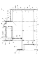
図1は本発明の一実施形態におけるユニット式建物の下階を示す間取り図であり、図2は図1のユニット式建物における上階を示す間取り図であり、図3は図1のユニット式建物における屋上階を示す間取り図である。また、図4は図1のユニット式建物を側面側から見て示す断面図である。なお、図1〜図3において、紙面上方側を北、下方側を南、右側を東、左側を西の方向と仮定する。従って、図4においては、紙面右側が北、左側が南、手前側が東、奥側が西の方向と仮定される。
Hereinafter, an embodiment of the present invention will be described in detail with reference to the drawings.
FIG. 1 is a floor plan showing a lower floor of a unit type building in one embodiment of the present invention, FIG. 2 is a floor plan showing an upper floor in the unit type building of FIG. 1, and FIG. 3 is a unit type of FIG. It is a floor plan which shows the rooftop floor in a building. 4 is a cross-sectional view of the unit building of FIG. 1 as viewed from the side. 1 to 3, it is assumed that the upper side of the drawing is north, the lower side is south, the right side is east, and the left side is west. Therefore, in FIG. 4, it is assumed that the right side of the page is north, the left side is south, the front side is east, and the back side is west.

まず、本実施形態のユニット式建物における下階1の間取りについて、図1および図4を参照しながら説明する。
図1に示すように、建物本体Hの下階1の西側には、建物本体Hの南側に向けて開口した玄関10が設けられている。玄関10は、玄関ポーチ11と、玄関ポーチ11から連続する土間床12と、玄関ポーチ11と土間床12との間を仕切る玄関扉13と、玄関ホール14とからなる。
First, the floor plan of the lower floor 1 in the unit type building of this embodiment will be described with reference to FIGS. 1 and 4.
As shown in FIG. 1, an entrance 10 that opens toward the south side of the building body H is provided on the west side of the lower floor 1 of the building body H. The entrance 10 includes an entrance porch 11, a dirt floor 12 continuous from the entrance porch 11, an entrance door 13 that partitions the entrance porch 11 and the dirt floor 12, and an entrance hall 14.

また、玄関10の北側には、部屋15が設けられている。この部屋15は、図示したような畳空間(和室)であってもよいし、ここでは図示しない玄関10の土間床12から連通する土間収納であってもよく、所望する仕様に任意に変更可能な態様を有してなるマルチルームとしての機能を備えている。また、部屋15の西側の壁面には窓15aが設けられており、当該窓15aから入射した光で採光可能になっている。さらに、窓15aの外部側には、後述する上階2の主寝室25(後述する図2参照)側まで延在する縦格子ルーバーRが立設されており、縦格子ルーバーRは断面台形状のルーバーを用いることで、部屋15内における眺望・採光を拡大しつつ外部から部屋15を隠すことによって、当該外部からの視線を減少させ、覗かれ難くなっている。すなわち、プライバシーを保護することができるようになっている。なお、この場合、部屋15の西側(窓15aに面する窓際)は、板の間15bとなっている。   A room 15 is provided on the north side of the entrance 10. The room 15 may be a tatami space (Japanese-style room) as shown in the figure, or may be a dirt storage communicated from the dirt floor 12 of the entrance 10 (not shown here), and can be arbitrarily changed to a desired specification. It has a function as a multi-room having such a mode. Further, a window 15a is provided on the wall surface on the west side of the room 15, and lighting is possible with light incident from the window 15a. Further, a vertical lattice louver R extending up to a main bedroom 25 (see FIG. 2 described later) on the upper floor 2 described later is provided on the outer side of the window 15a, and the vertical lattice louver R is trapezoidal in cross section. By hiding the room 15 from the outside while enlarging the view / lighting in the room 15, the line of sight from the outside is reduced, and it is difficult to look into the room. That is, privacy can be protected. In this case, the west side of the room 15 (the window facing the window 15a) is a space 15b.

部屋15の東側には、引き戸15cを介してダイニング・キッチン16が設けられている。ダイニング・キッチン16に面した外周側(北側)の壁面には窓16aが設けられており、当該窓16aから入射した光で採光可能になっている。   A dining kitchen 16 is provided on the east side of the room 15 through a sliding door 15c. A window 16a is provided on the wall surface on the outer peripheral side (north side) facing the dining kitchen 16, and lighting is possible with light incident from the window 16a.

ダイニング・キッチン16の東側には、浴室17および洗面所18が設けられている。これら浴室17および洗面所18の間(すなわち、浴室17の南側)には、浴室17の出入口17aが設けられている。洗面所18の北側(浴室17の出入口17a側)の空間は、入浴時の脱衣所としても機能する。また、洗面所18の出入口18aは南側に設けられている。これら浴室17および洗面所18の東側の壁面には、それぞれ窓17b,18bが設けられ、採光可能になっている。   A bathroom 17 and a washroom 18 are provided on the east side of the dining kitchen 16. Between the bathroom 17 and the washroom 18 (that is, the south side of the bathroom 17), an entrance 17a of the bathroom 17 is provided. The space on the north side of the washroom 18 (the entrance 17a side of the bathroom 17) also functions as a dressing room when taking a bath. Moreover, the entrance / exit 18a of the washroom 18 is provided in the south side. Windows 17b and 18b are provided on the east wall of the bathroom 17 and the washroom 18, respectively, so that lighting is possible.

ダイニング・キッチン16の南側には、図4にも示すように、大空間のリビング19が当該ダイニング・キッチン16と連通して設けられている。つまり、ダイニング・キッチン16の南側部分は、リビング19と一体化している。また、これらダイニング・キッチン16およびリビング19の中間部の西側には、玄関ホール14に面した出入口16bが設けられている。   As shown in FIG. 4, a large living room 19 is provided on the south side of the dining kitchen 16 so as to communicate with the dining kitchen 16. That is, the south part of the dining kitchen 16 is integrated with the living room 19. An entrance 16b facing the entrance hall 14 is provided on the west side of the middle part of the dining kitchen 16 and the living room 19.

リビング19の南側には、ダイニング・キッチン16と対向する位置に、屋外へ通じる開口部20が設けられ、この開口部20には窓20aが設けられている。このため、窓20aから入射した光を、リビング19を介してダイニング・キッチン16まで届かせることができ、ダイニング・キッチン16の採光を良好にすることができる。また、開口部20の南側には、窓20aを介して建物本体Hの外方に面したデッキ空間21が設けられている。デッキ空間21の高さは、例えばリビング19およびダイニング・キッチン16の床高さ(すなわち、図4に示す下階1の床1aの高さ)に等しくすることで、屋内外の空間を一体に見せることができるようになっている。   On the south side of the living room 19, an opening 20 leading to the outdoors is provided at a position facing the dining kitchen 16, and a window 20 a is provided in the opening 20. For this reason, the light incident from the window 20a can reach the dining kitchen 16 through the living room 19, and the lighting of the dining kitchen 16 can be improved. A deck space 21 facing the outside of the building body H is provided on the south side of the opening 20 through a window 20a. The height of the deck space 21 is made equal to, for example, the floor height of the living room 19 and the dining kitchen 16 (that is, the height of the floor 1a of the lower floor 1 shown in FIG. 4) so that the indoor and outdoor spaces are integrated. You can show it.

リビング19の東側には、引き戸19aを介して階段室22が設けられている。この階段室22は、下階1から後述する収納空間4の設けられた屋上階3に亙って設けられており、下階1の床1a(図4参照)から後述の上階2の床2aに至る第1階段22aと、上階2の床2aから屋上階3(すなわち、収納空間4)の床3aに至る第2階段22b(後述する図2,図3参照)とを備えている。なお、ここでは、第1および第2階段22a,22bは、折り返し階段とされているが、一例であってこれに限ることはない。
また、下階1の階段室22と洗面所18との間における東側の壁面には、窓22cが設けられ、採光および通気が可能となっている。
なお、この窓22cの下方、つまり下階1の床1a近傍の壁面には地窓が設けられることが好ましい。また、ここでは図示省略するが、これら第1および第2階段22a,22bは、複数の踏み板間の蹴上げ部を開口させたスケルトン式の階段とすることが好ましい。これにより、地窓から流入する外気を、複数の踏み板間の開口(隙間)を通じて上方の収納空間4(詳細には、後述する収納空間4の上方に設けられる天窓38)へと流通させることができるので、下階1の空気を上昇し易くさせると共に、当該空気を収納空間4の天窓38から排気させ易くすることができる。
On the east side of the living room 19, a staircase 22 is provided through a sliding door 19a. The staircase 22 is provided from the lower floor 1 to the rooftop floor 3 where the storage space 4 described later is provided, and from the floor 1a of the lower floor 1 (see FIG. 4) to the floor of the upper floor 2 described later. The first staircase 22a leading to 2a and the second staircase 22b (refer to FIGS. 2 and 3 to be described later) from the floor 2a of the upper floor 2 to the floor 3a of the rooftop floor 3 (that is, the storage space 4). . Here, the first and second stairs 22a and 22b are folded stairs, but this is an example and the present invention is not limited to this.
Further, a window 22c is provided on the east wall surface between the staircase 22 and the washroom 18 on the lower floor 1, and lighting and ventilation are possible.
A ground window is preferably provided below the window 22c, that is, on the wall surface near the floor 1a of the lower floor 1. Although not shown here, it is preferable that the first and second steps 22a and 22b are skeleton-type steps in which kick-up portions between a plurality of treads are opened. Thereby, the outside air flowing in from the ground window can be circulated to the upper storage space 4 (specifically, the skylight 38 provided above the storage space 4 described later) through the openings (gap) between the plurality of treads. Therefore, the air in the lower floor 1 can be easily raised, and the air can be easily exhausted from the skylight 38 of the storage space 4.

さらに、下階1において、階段室22の第1階段22aの西側は、上階2へ向けた第1階段22aの下方に形成される階段下空間となっており、本実施形態の場合、当該階段下空間にトイレ23が設けられている。また、当該トイレ23の東側の壁面には窓23aが設けられ、採光および通気が可能となっている。   Furthermore, on the lower floor 1, the west side of the first staircase 22a of the staircase 22 is a space below the first staircase 22a toward the upper floor 2, and in this embodiment, A toilet 23 is provided in the space below the stairs. In addition, a window 23a is provided on the east wall of the toilet 23 so that lighting and ventilation are possible.

階段室22の南側であって、デッキ空間21の東側には、セレクトルーム24が設けられている。セレクトルーム24は、水廻り動線として機能させたり、防災備蓄等を収納するための備蓄庫として機能させたり、書斎として機能させたり等の種々の用途に利用することが可能となっている。因みに、本実施形態の場合、セレクトルーム24は在宅勤務者等が利用するための仕事部屋として機能する。また、このセレクトルーム24の東側の壁面には、窓24aが設けられており、採光可能となっている。   A select room 24 is provided on the south side of the staircase 22 and on the east side of the deck space 21. The select room 24 can be used for various purposes such as functioning as a water flow line, functioning as a stockpile for storing a disaster prevention stockpile, and functioning as a study. Incidentally, in the present embodiment, the select room 24 functions as a work room for use by telecommuters and the like. A window 24a is provided on the east wall of the select room 24 so that the daylight can be obtained.

次に、本実施形態のユニット式建物における上階2の間取りについて、図2および図4を参照しながら説明する。
図2に示すように、上階2において、下階1の部屋15(図1参照)の上方には主寝室25が設けられている。主寝室25の西側の壁面には窓25aが、北側の壁面には窓25bがそれぞれ設けられ、これら窓25a,25bから入射した光によって、当該主寝室25の採光を良好にすることができるようになっている。また、窓25aの外部側には、下階1の部屋15(図1参照)から延在する縦格子ルーバーRが立設されている。これにより、主寝室25内における眺望・採光を拡大しつつ外部から主寝室25を隠すことによって、当該外部からの視線を減少させ、主寝室25内が覗かれ難くなっている。すなわち、主寝室25におけるプライバシーを保護することができるようになっている。
Next, the floor plan of the upper floor 2 in the unit type building of this embodiment will be described with reference to FIGS. 2 and 4.
As shown in FIG. 2, in the upper floor 2, a main bedroom 25 is provided above the room 15 (see FIG. 1) on the lower floor 1. A window 25a is provided on the west wall surface of the main bedroom 25, and a window 25b is provided on the north wall surface, and the light incident from the windows 25a and 25b can be used to improve the lighting of the main bedroom 25. It has become. A vertical lattice louver R extending from the room 15 on the lower floor 1 (see FIG. 1) is erected on the outside of the window 25a. Thus, by hiding the main bedroom 25 from the outside while enlarging the view / lighting in the main bedroom 25, the line of sight from the outside is reduced, and the inside of the main bedroom 25 is difficult to look into. That is, privacy in the main bedroom 25 can be protected.

また、主寝室25には、南側にクローゼット26が設けられており、当該クローゼット26の南側には、トイレ27が設けられている。このトイレ27の東側は、当該トイレ27の出入口を介して、後述する多目的スペース31に面しており、このトイレ27の出入口近傍に当該多目的スペース31に面した主寝室25の出入口が設けられている。また、トイレ27の南側には、玄関10の上方に下階1の天井と略同じ高さに位置する庇Qが設けられている。   The main bedroom 25 is provided with a closet 26 on the south side, and a toilet 27 is provided on the south side of the closet 26. The east side of the toilet 27 faces a multipurpose space 31 to be described later via an entrance of the toilet 27, and an entrance of the main bedroom 25 facing the multipurpose space 31 is provided in the vicinity of the entrance of the toilet 27. Yes. In addition, on the south side of the toilet 27, a ridge Q is provided above the entrance 10 and located at substantially the same height as the ceiling of the lower floor 1.

なお、かかるトイレ27を設けない場合、この位置までクローゼット26を延在させることで、ウォークスルークローゼットを形成することができる。この場合、ウォークスルークローゼットには、主寝室25に面した出入口と、トイレ27側の出入口と、の二つの出入口を介して出入りすることができる。従って、ウォークスルークローゼットには、主寝室25の内外双方から出入り可能となるため、衣類等を収納する際に短い動線で移動可能であると共に、主寝室25内に入ることなく、主寝室25の外(すなわち、後述の多目的スペース31側)からでも直接内部まで入り込んで収納作業できる利点を有することが可能となる利点を備えることができる。   If the toilet 27 is not provided, the walk-through closet can be formed by extending the closet 26 to this position. In this case, the walk-through closet can be accessed through two entrances: an entrance facing the main bedroom 25 and an entrance on the toilet 27 side. Accordingly, since the walk-through closet can be entered and exited from both inside and outside of the main bedroom 25, the clothes can be moved with a short flow line when storing clothes and the main bedroom 25 without entering the main bedroom 25. It is possible to provide an advantage that it is possible to have an advantage of being able to enter directly into the interior even from the outside (that is, the multipurpose space 31 side described later).

主寝室25の東側には、第1子供室28と第2子供室29とが設けられている。これら第1および第2子供室28,29は、これらの略中央部に立設された間仕切り収納30によって、二つの子供室に分離されている。この間仕切り収納30は、3つの収納棚等の収納家具から構成され、第1子供室28専用の収納棚30aと、第2子供室29専用の収納棚30bと、略中央で双方の子供室28,29の双方に間仕切られ、これら第1および第2子供室28,29のそれぞれで使用可能な棚30cと、を備えている。このため、当該間仕切り収納30を可動式のものにすれば、当該間仕切り収納30を移動して開放することで、一つの子供室とする広い空間を確保することも可能となっている。また、これら第1および第2子供室28,29の北側の壁面には、それぞれ窓28a,29aが設けられると共に、第2子供室29の東側の壁面には、窓29bが設けられており、採光可能となっている。   On the east side of the main bedroom 25, a first child room 28 and a second child room 29 are provided. The first and second child rooms 28 and 29 are separated into two child rooms by a partition housing 30 erected at the substantially central portion thereof. The partition storage 30 includes storage furniture such as three storage shelves, a storage shelf 30a dedicated to the first child room 28, a storage shelf 30b dedicated to the second child room 29, and both of the child rooms 28 at approximately the center. , 29, and a shelf 30c that can be used in each of the first and second child rooms 28, 29. For this reason, if the partition storage 30 is movable, it is possible to secure a wide space as one child room by moving and opening the partition storage 30. In addition, windows 28a and 29a are provided on the north wall surfaces of the first and second child rooms 28 and 29, respectively, and windows 29b are provided on the east wall surface of the second child room 29. Daylighting is possible.

第1および第2子供室28,29の南側には、図4にも示すように、多目的スペース31が設けられている。この多目的スペース31は、居住者の所望する目的に応じて仕様を変更することが可能となっており、本実施形態では、子供用の勉強スペースとして機能するようになっている。この場合、第1および第2子供室28,29は、子供用の寝室および遊びスペースとして機能すると共に、多目的スペース31は、勉強スペースとして機能することにより、「遊ぶ・寝る」を目的とするスペースと、「学ぶ」を目的とするスペースとを分離して機能させることができる。この多目的スペース31の東側の壁面には、窓31aが設けられており、採光可能となっている。また、多目的スペース31には、上階2の他の空間(主寝室25、第1および第2子供室28,29、階段室22)との間に仕切はない。   As shown in FIG. 4, a multipurpose space 31 is provided on the south side of the first and second child rooms 28 and 29. The specifications of the multipurpose space 31 can be changed according to the purpose desired by the resident, and in this embodiment, the multipurpose space 31 functions as a study space for children. In this case, the first and second children's rooms 28 and 29 function as children's bedrooms and play spaces, and the multi-purpose space 31 functions as a study space, thereby being a space for “playing and sleeping”. Can be separated from the space for “learning”. A window 31a is provided on the wall on the east side of the multipurpose space 31, and lighting is possible. Further, the multipurpose space 31 has no partition between the other spaces of the upper floor 2 (the main bedroom 25, the first and second child rooms 28 and 29, and the staircase 22).

多目的スペース31の東側には、階段室22が設けられている。この上階2の階段室22の東側の壁面(具体的には、上階2と屋上階3とを結ぶ第2階段22bに面する東側の壁面)には窓22dが設けられており、採光および通気が可能となっている。また、多目的スペース31の南側には、屋外へ通じる開口部32が設けられ、この開口部32には窓32aが設けられている(図4参照)。このため、窓32aから入射した光によって、多目的スペース31の採光を良好にすることができる。   A staircase 22 is provided on the east side of the multipurpose space 31. A window 22d is provided on the east wall of the staircase 22 on the upper floor 2 (specifically, the east wall facing the second staircase 22b connecting the upper floor 2 and the rooftop floor 3). And ventilation is possible. An opening 32 leading to the outdoors is provided on the south side of the multipurpose space 31, and a window 32a is provided in the opening 32 (see FIG. 4). For this reason, the lighting of the multipurpose space 31 can be made favorable by the light incident from the window 32a.

また、開口部32の南側には、窓32aを介してルーフバルコニー33が設けられている。すなわち、窓32aはルーフバルコニー33の出入口として機能する。ルーフバルコニー33の高さは、図4に示すように、多目的スペース31、第1および第2子供室28,29や図4には図示しない主寝室25等の床高さ(すなわち、上階2の床2aの高さ)に等しく、屋内外の空間を一体に見せることができる。また、ルーフバルコニー33の南側に位置する外周部には、パラペット部40からなる手摺壁Tが設けられている。手摺壁Tは建物の外壁と一体化して設けられている。   A roof balcony 33 is provided on the south side of the opening 32 through a window 32a. That is, the window 32 a functions as an entrance / exit of the roof balcony 33. As shown in FIG. 4, the height of the roof balcony 33 is the floor height of the multipurpose space 31, the first and second child rooms 28 and 29, the main bedroom 25 not shown in FIG. It is equal to the height of the floor 2a), and the indoor and outdoor spaces can be seen together. In addition, a handrail wall T including a parapet portion 40 is provided on the outer peripheral portion located on the south side of the roof balcony 33. The handrail wall T is provided integrally with the outer wall of the building.

次に、本実施形態のユニット式建物における収納空間4の設けられた屋上階3の間取りについて、図3および図4を参照しながら説明する。
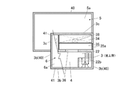
図3に示すように、本実施形態のユニット式建物は、陸屋根5の一部(すなわち、屋上階3部分であって、建物本体Hの略中央から南側部分における東西方向)に、当該陸屋根5の略平坦な屋根面5aよりも高い位置に配置され、屋根面5aと同じく略平坦な屋根面6aを有する高屋根部6を備えている。この高屋根部6の屋根面6aと、陸屋根5の屋根面5aとの間には、屋上階3が形成されており、当該屋上階3には南側に収納空間4が設けられている。
Next, the floor plan 3 provided with the storage space 4 in the unit type building of the present embodiment will be described with reference to FIGS. 3 and 4.
As shown in FIG. 3, the unit type building of the present embodiment has a flat roof 5 on a part of the flat roof 5 (that is, the roof top floor 3 portion, from the approximate center of the building main body H to the east-west direction in the south side). It is arranged at a position higher than the substantially flat roof surface 5a, and has a high roof portion 6 having a substantially flat roof surface 6a similar to the roof surface 5a. A rooftop floor 3 is formed between the roof surface 6a of the high roof portion 6 and the roof surface 5a of the land roof 5, and a storage space 4 is provided on the south side of the rooftop floor 3.

また、収納空間4の東側には、階段室22が設けられており、上階2の床2aから屋上階3の床3aに至る第2階段22bによって、上階2と行き来が可能となっている。このように、建物本体Hに下階1から上階2を介して屋上階3(より詳細には、収納空間4)に至る第1および第2階段22a,22bを有する階段室22が設けられているので、収納空間4へアクセスする際は当該階段室22を利用すればよく、とりわけ下階1から収納空間4への行き来が容易になっている。従って、収納空間4へのアクセスがし易い分、屋上階3に設けられた収納空間4の使い勝手が向上されている。   In addition, a staircase 22 is provided on the east side of the storage space 4, and it is possible to go to and from the upper floor 2 by the second staircase 22 b from the floor 2 a of the upper floor 2 to the floor 3 a of the rooftop floor 3. Yes. Thus, the building main body H is provided with the staircase 22 having the first and second steps 22a and 22b from the lower floor 1 through the upper floor 2 to the rooftop floor 3 (more specifically, the storage space 4). Therefore, when the storage space 4 is accessed, the staircase 22 may be used. In particular, it is easy to go from the lower floor 1 to the storage space 4. Therefore, the ease of use of the storage space 4 provided on the rooftop floor 3 is improved because the storage space 4 is easily accessible.

このとき、収納空間4の天井高は、0.8m〜1.4mに設定されている。これにより、人(居住者など)が収納空間4に入って、何とか作業ができる最低限の高さを確保でき、また、このように天井高を必要最小限に抑えることで、ユニット式建物の高さが高くなることによって隣接する建物に及ぼす日照減少等の影響を極力少なくすることができるようになっている。   At this time, the ceiling height of the storage space 4 is set to 0.8 m to 1.4 m. As a result, it is possible to secure the minimum height at which people (residents, etc.) can enter the storage space 4 and somehow work, and by keeping the ceiling height to the minimum necessary in this way, By increasing the height, it is possible to minimize the influence of a reduction in sunlight on adjacent buildings.

収納空間4の北側には、上階2の上方(すなわち、多目的スペース31)に向けて開口する吹き抜け部34が設けられており、この吹き抜け部34と収納空間4との間には、吹き抜け部34に面した通路35が形成されている。通路35の東側の壁面には窓35aが設けられており、採光可能になっている。また、通路35の南側には開口部36が設けられ、収納空間4と行き来可能になっている。なお、この場合、通路35の北側には強化ガラス等からなる壁部37が立設されている。吹き抜け部34の上方に設けられた天井には、高屋根部6の屋根面6aから突出するように天窓38が設けられている。これにより、屋上階3や上階2の通風・採光が可能となっている。   On the north side of the storage space 4, a blow-off portion 34 that opens toward the upper side of the upper floor 2 (that is, the multipurpose space 31) is provided, and a blow-off portion is provided between the blow-off portion 34 and the storage space 4. A passage 35 facing 34 is formed. A window 35a is provided on the east wall of the passage 35 so that it can be daylighted. Further, an opening 36 is provided on the south side of the passage 35 so that it can go to and from the storage space 4. In this case, a wall portion 37 made of tempered glass or the like is erected on the north side of the passage 35. A skylight 38 is provided on the ceiling provided above the atrium 34 so as to protrude from the roof surface 6 a of the high roof 6. Thereby, ventilation and lighting of the rooftop floor 3 and the upper floor 2 are possible.

また、吹き抜け部34の北側には、上階2の主寝室25、第1および第2子供室28,29の上方に位置する陸屋根5が設けられている。陸屋根5は、略平坦な屋根面5aを有しており、この陸屋根5の屋根面5aの外周縁部には、パラペット部40が立設されている。また、屋上階3を形成する高屋根部6と陸屋根5との境界(屋上階3の北側から西側の一部にかけた外周縁部)には、境界壁3cが立設されている。さらに、屋上階3の東側と、南側と、西側の一部との三方には、陸屋根5の外周縁部に設けられたパラペット部40が上方へ延在することで形成された外周壁3bが立設されている。すなわち、屋上階3は、東側と南側と西側の一部とに設けられた外周壁3bと、北側と西側の一部とに設けられた境界壁3cと、によって囲まれている。また、陸屋根5の一部として嵩上げされた屋上階3の上方に位置する高屋根部6の屋根面6aの外周縁部には、上端が屋根面6a(陸屋根5のパラペット部40)よりも高いパラペット部41が設けられている。なお、屋上階3における収納空間4の南側には、下方(すなわち、上階2)に設けられたルーフバルコニー33が位置している。   Further, on the north side of the atrium 34, a land roof 5 is provided that is located above the main bedroom 25 on the upper floor 2 and the first and second child rooms 28 and 29. The land roof 5 has a substantially flat roof surface 5 a, and a parapet portion 40 is erected on the outer peripheral edge of the roof surface 5 a of the land roof 5. In addition, a boundary wall 3c is erected on the boundary between the high roof portion 6 and the flat roof 5 forming the rooftop floor 3 (the outer peripheral edge portion from the north side to the west side of the rooftop floor 3). Furthermore, on the east side, the south side, and a part of the west side of the rooftop floor 3, there is an outer peripheral wall 3b formed by extending a parapet portion 40 provided on the outer peripheral edge of the land roof 5 upward. It is erected. That is, the rooftop floor 3 is surrounded by the outer peripheral wall 3b provided on the east side, the south side, and a part of the west side, and the boundary wall 3c provided on the north side and a part of the west side. Moreover, the upper end is higher than the roof surface 6a (the parapet portion 40 of the land roof 5) at the outer peripheral edge of the roof surface 6a of the high roof portion 6 located above the rooftop floor 3 raised as a part of the land roof 5. A parapet portion 41 is provided. Note that a roof balcony 33 provided below (that is, the upper floor 2) is located on the south side of the storage space 4 on the rooftop floor 3.

このように、本実施形態のユニット式建物では、収納空間4を備える屋上階3が、陸屋根5のパラペット部40を上方に延在させてなる外周壁3bと、当該屋上階3と陸屋根5との境界に設けられる境界壁3cと、によって囲まれて形成されているので、建物全体の外観に統一感を持たせることができ、外観の意匠を向上させることができるようになっている。   Thus, in the unit type building of this embodiment, the rooftop floor 3 provided with the storage space 4 has the outer peripheral wall 3b formed by extending the parapet part 40 of the rooftop 5 upward, the rooftop floor 3 and the rooftop 5. Since it is surrounded by the boundary wall 3c provided at the boundary, the overall appearance of the building can be given a unified feeling, and the design of the external appearance can be improved.

なお、屋上階3の階段室22に面する壁面には、開閉可能な窓が設けられていることが好ましい。この場合、当該窓を介して階段室22の採光を図れるばかりか、当該窓が開閉可能であることにより、収納空間4における通気が可能となる。さらに、階段室22が下階1から上階2を介して屋上階3の収納空間4に亙って形成されているので、階段室22の上下に亙って屋内(建物内)の空気を効果的に流通させることができる利点をも備えることができる。つまり、下階1の空気を、階段室22を通じて上方に位置する収納空間4の窓から排気することができるようになる。
従って、より好ましくは下階1に図示省略する地窓を設けたり、階段室22の第1および第2階段22a,22bを複数の踏み板間の蹴上げ部を開口させたスケルトン式の階段にしたりすれば、地窓から流入する外気を、複数の踏み板間の開口(隙間)を通じて上方に位置する屋上階3の窓へと流通させることができるので、下階1の空気を上昇し易くさせると共に、当該空気を屋上階3の窓から排気させ易くすることができるようになる。
In addition, it is preferable that the wall surface facing the staircase 22 on the rooftop floor 3 is provided with a window that can be opened and closed. In this case, not only lighting of the staircase 22 can be achieved through the window, but also the ventilation of the storage space 4 is enabled by opening and closing the window. Further, since the staircase 22 is formed from the lower floor 1 through the upper floor 2 to the storage space 4 of the rooftop floor 3, the indoor (inside of the building) air is drawn up and down the staircase 22. The advantage that it can be distributed effectively can also be provided. That is, the air in the lower floor 1 can be exhausted from the window of the storage space 4 positioned above through the staircase 22.
Therefore, more preferably, a ground window (not shown) is provided on the lower floor 1, or the first and second steps 22 a and 22 b of the staircase 22 are changed to a skeleton type staircase in which a lifted portion between a plurality of treads is opened. For example, the outside air flowing in from the ground window can be circulated to the window on the rooftop floor 3 located above through the openings (gap) between the plurality of treads, so that the air in the lower floor 1 can be easily raised, The air can be easily exhausted from the window on the rooftop floor 3.

ここで、上述した陸屋根5および屋上階3を構築する陸屋根ユニット(第1陸屋根ユニット50,第2陸屋根ユニット60)について、図4〜図8を参照しながら詳細に説明する。陸屋根5および屋上階3は、図4に示すように、垂直方向に単数または複数配置される建物ユニットUによって構築される建物本体Hの上部に配置され、略平坦な屋根面5aを有する陸屋根5を形成する第1陸屋根ユニット50と、同じく略平坦な屋根面6aを有する屋上階3としての高屋根部6を形成する第2陸屋根ユニット60からなる。すなわち、陸屋根5は、規定寸法からなる第1陸屋根ユニット50により構築されており、屋上階3は、第1陸屋根ユニット50に比べて高さ方向の寸法が嵩上げされてなる第2陸屋根ユニット60により構築されている。   Here, the land roof units (the first land roof unit 50 and the second land roof unit 60) that construct the above-described land roof 5 and rooftop floor 3 will be described in detail with reference to FIGS. 4 to 8. As shown in FIG. 4, the flat roof 5 and the rooftop floor 3 are arranged on the upper part of the building body H constructed by a single or a plurality of building units U arranged in the vertical direction, and have a substantially flat roof surface 5 a. And a second flat roof unit 60 that forms a high roof portion 6 as the rooftop floor 3 having a substantially flat roof surface 6a. That is, the flat roof 5 is constructed by a first flat roof unit 50 having a prescribed size, and the rooftop floor 3 is formed by a second flat roof unit 60 having a height dimension raised compared to the first flat roof unit 50. Has been built.

この第2陸屋根ユニット60は、図4に示すように、直下に位置する建物ユニットUの天井梁U1の上面側に、床3aを形成する床材が配設されている。このため、当該第2陸屋根ユニット60内の部屋である収納空間4を直下の建物ユニットU内の部屋(例えば、多目的スペース31)のロフトや小屋裏空間として利用することができるようになっている。なお、第1陸屋根ユニット50は、従来から広く使用されている通常の陸屋根を構築する規定寸法からなるユニット(すなわち、第2陸屋根ユニット60の後述する複数の束64…を備えていない構造)であるため、ここでは分解斜視図を用いた詳細な説明は割愛する。   As shown in FIG. 4, the second flat roof unit 60 is provided with a floor material forming the floor 3 a on the upper surface side of the ceiling beam U <b> 1 of the building unit U located immediately below. For this reason, the storage space 4 that is a room in the second flat roof unit 60 can be used as a loft or a shed space in a room (for example, the multipurpose space 31) in the building unit U directly below. . The first flat roof unit 50 is a unit having a prescribed size for constructing a normal flat roof that has been widely used conventionally (that is, a structure that does not include a plurality of bundles 64 described later of the second flat roof unit 60). Therefore, detailed description using an exploded perspective view is omitted here.

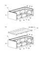
具体的に、第2陸屋根ユニット60は、建物本体Hの上方側に位置する矩形状の建物ユニットUの上面に載置され、図5(a)に示すように、長辺側に配置される一対の長辺梁61,61および短辺側に配置される一対の短辺梁62,62からなる矩形状の小屋パネル63と、小屋パネル63の上面に立設される複数の束64…と、を有している。   Specifically, the second flat roof unit 60 is placed on the upper surface of the rectangular building unit U located on the upper side of the building body H, and is arranged on the long side as shown in FIG. A rectangular hut panel 63 composed of a pair of long side beams 61, 61 and a pair of short side beams 62, 62 arranged on the short side, and a plurality of bundles 64 ... standing on the upper surface of the shed panel 63. ,have.

このとき、複数の束64…は、少なくとも、小屋パネル63の四隅と、一対の長辺梁61,61上の四隅にそれぞれ対応し且つ当該四隅から長辺梁61,61の中央側に離間する位置と、に設けられている。また、四隅の束64と、当該四隅の束64にそれぞれ対応する中央側の束64との間にはブレースBRが配設されている。これにより、当該第2陸屋根ユニット60の剛性を高めることができるようになっている。よって、地震・風などにより、ユニット式建物の外部から水平方向(横方向)に力が入力されたとしても、ブレースBRの引張力により、ユニット式建物が変形するのを未然に防止することができるようになっている。   At this time, the plurality of bundles 64... Correspond to at least the four corners of the cabin panel 63 and the four corners on the pair of long side beams 61 and 61 and are separated from the four corners to the center side of the long side beams 61 and 61. Position. A brace BR is disposed between the bundle 64 at the four corners and the bundle 64 on the center side corresponding to the bundle 64 at the four corners. Thereby, the rigidity of the second flat roof unit 60 can be increased. Therefore, even if a force is input in the horizontal direction (lateral direction) from the outside of the unit type building due to an earthquake or wind, it is possible to prevent the unit type building from being deformed by the tensile force of the brace BR. It can be done.

また、この場合、複数の束64…のうち、各長辺梁61上における中央側の束64,64間は離間していると共にブレースBRは配設されないため、開口部を設けることが可能となっている。そして、当該開口部には、第2陸屋根ユニット60の内外に連通する通路を設けることが可能となっている。この場合、一対の長辺梁61,61のそれぞれに開口部を形成して第2陸屋根ユニット60を貫通するように通路を設けることもできる。
なお、この場合、四隅の束64のうち、小屋パネル63の短辺方向(すなわち、短辺梁62上)に隣り合う束64,64の間に、更にブレースBRが配設されていることが好ましい。これにより、第2陸屋根ユニット60の剛性をより一段と向上させることが可能となる利点を備えることができる。
Further, in this case, among the plurality of bundles 64..., The center-side bundles 64 and 64 on each long side beam 61 are separated from each other and the brace BR is not provided, so that an opening can be provided. It has become. The opening can be provided with a passage communicating with the inside and outside of the second flat roof unit 60. In this case, a passage can be provided so as to penetrate the second flat roof unit 60 by forming an opening in each of the pair of long side beams 61, 61.
In this case, among the bundles 64 at the four corners, a brace BR may be further disposed between the bundles 64 and 64 adjacent to each other in the short side direction of the hut panel 63 (that is, on the short side beam 62). preferable. Thereby, the advantage which can improve the rigidity of the 2nd land roof unit 60 more can be provided.

また、第2陸屋根ユニット60は、図5(b)および図7(b)に示すように、複数の束64…に取り付けられる外壁受部65と、外壁受部65に取り付けられ、後述する屋根パネル69(後述の図6(b)参照)よりも上方に突出するパラペット部41(図3および図5(c)等参照)を構成するためのパラペット用下地66と、を更に備えている。そして、図5(c)に示すように、小屋パネル63の外周縁部と、外壁受部65と、パラペット用下地66とに対して外壁材である外周壁3bが取り付けられている。すなわち、第2陸屋根ユニット60は、複数の束64…の外側に設けられる外周壁3b(外壁材)を備えている。このとき、パラペット用下地66に取り付けられた外周壁3bの上部側がパラペット部41として構成される。   Further, as shown in FIGS. 5B and 7B, the second land roof unit 60 is attached to the outer wall receiving portion 65 and the outer wall receiving portion 65 attached to the plurality of bundles 64. It further includes a parapet base 66 for constituting a parapet portion 41 (see FIG. 3 and FIG. 5C, etc.) protruding upward from the panel 69 (see FIG. 6B described later). And as shown in FIG.5 (c), the outer peripheral wall 3b which is an outer wall material is attached with respect to the outer-periphery edge part of the hut panel 63, the outer wall receiving part 65, and the base 66 for parapets. That is, the second flat roof unit 60 includes an outer peripheral wall 3b (outer wall material) provided outside the plurality of bundles 64. At this time, the upper side of the outer peripheral wall 3 b attached to the parapet base 66 is configured as a parapet portion 41.

さらに、第2陸屋根ユニット60は、図6(a)に示すように、パラペット用下地66の内周側に設けられるサイディング68を有すると共に、図6(b)に示すように、複数の束64…の上端部に設けられる屋根パネル69を備えている。つまり、第2陸屋根ユニット60は、複数の束64の高さ寸法を変更することで、内部に形成される収納空間4の天井高を、0.8m〜1.4mに設定可能となっている。   Further, the second flat roof unit 60 has a siding 68 provided on the inner peripheral side of the parapet base 66 as shown in FIG. 6A, and a plurality of bundles 64 as shown in FIG. 6B. The roof panel 69 provided in the upper end part of ... is provided. That is, the second flat roof unit 60 can set the ceiling height of the storage space 4 formed therein to 0.8 m to 1.4 m by changing the height dimension of the plurality of bundles 64. .

このように、第2陸屋根ユニット60では、小屋パネル63と、外壁受部65と、パラペット用下地66とによって外壁材である外周壁3bを受けるので、屋根パネル69よりも上方に突出してパラペット部41を構成することができると共に、第1陸屋根ユニット50に比べて高さ方向の寸法が嵩上げされてなる第2陸屋根ユニット60の剛性を高めることができるようになっている。   Thus, in the 2nd land roof unit 60, since the outer peripheral wall 3b which is an outer wall material is received by the hut panel 63, the outer wall receiving part 65, and the parapet base 66, it protrudes upwards rather than the roof panel 69, and a parapet part. 41, and the rigidity of the second flat roof unit 60 in which the dimension in the height direction is raised compared to the first flat roof unit 50 can be increased.

このような第2陸屋根ユニット60は、工場にて製造される際、防水処理を施された状態(すなわち、屋根パネル69に図示省略する防水シートを敷設する等の防水処理が仕上げられた状態)で形成されている。このとき、図7および図8(a),(b)に示すように、屋根パネル69の上面側には吊り込み作業に用いられる吊受材としての吊ナット70が設けられている。この吊ナット70は、屋根パネル69において、第2陸屋根ユニット60の四隅の束64の直上付近に位置するように配設されている。そして、第2陸屋根ユニット60は、建築現場にてクレーン装置(図示省略)等によって屋根パネル69の上面側の吊ナット70を介して建物ユニットUの上方から吊り込まれ、当該建物ユニットUの上面に載置されるようになっている。   Such a second flat roof unit 60 is in a state of being waterproofed when manufactured at a factory (that is, a state of waterproofing such as laying a waterproof sheet (not shown) on the roof panel 69). It is formed with. At this time, as shown in FIG. 7 and FIGS. 8A and 8B, a suspension nut 70 is provided on the upper surface side of the roof panel 69 as a suspension receiving material used for suspension work. The suspension nut 70 is disposed on the roof panel 69 so as to be positioned immediately above the bundle 64 at the four corners of the second land roof unit 60. And the 2nd land roof unit 60 is suspended from the upper direction of the building unit U via the hanging nut 70 of the upper surface side of the roof panel 69 by a crane apparatus (illustration omitted) etc. in a construction site, and the upper surface of the said building unit U is concerned. It is supposed to be placed on.

従って、第2陸屋根ユニット60は、屋根パネル69に設けられた吊ナット70を用いて建物ユニットUの上方から吊り込むことができるので、当該第2陸屋根ユニット60に対して予め工場において防水処理を仕上げた状態で建築現場に輸送することができるようになっている。よって、建築現場における当該防水処理を省くことができ、建築現場における作業をより一層軽減できると共に、施工期間の更なる短期化を図ることが可能となっている。   Therefore, since the second flat roof unit 60 can be suspended from above the building unit U using the suspension nut 70 provided on the roof panel 69, the second flat roof unit 60 is previously waterproofed at the factory. The finished product can be transported to the construction site. Therefore, the waterproof treatment at the construction site can be omitted, the work at the construction site can be further reduced, and the construction period can be further shortened.

しかも、第2陸屋根ユニット60は、その骨格となる軸組(小屋軸組)を束64などの二次部材によって構成することにより、上述した建築基準法における日影規制等の制限をオーバーすることなく、第1陸屋根ユニット50(通常の陸屋根ユニット)に比べて、高さ方向の寸法を嵩上げすることが可能となっている。   Moreover, the second flat roof unit 60 is configured with a frame (shed shaft) that is a skeleton of the second flat roof unit 60 by a secondary member such as a bundle 64, thereby exceeding the limitation of the shade control and the like in the Building Standard Act described above. As compared with the first flat roof unit 50 (ordinary flat roof unit), the height dimension can be increased.

さらに、かかる構成の第2陸屋根ユニット60は、図9(a),(b)および図10(a)〜(c)に示すように、同一の向きで配置され、水平方向に隣り合う他の第2陸屋根ユニット60との間で、隣接する束64,64同士が図示しない接続部材(接続プレートやボルト、ナット等)を介して固定されるようになっている。   Furthermore, as shown in FIGS. 9A and 9B and FIGS. 10A to 10C, the second flat roof unit 60 having such a configuration is arranged in the same direction and is adjacent to the other in the horizontal direction. Between the second flat roof unit 60, adjacent bundles 64, 64 are fixed via connection members (connection plates, bolts, nuts, etc.) not shown.

以上、説明したように、本実施形態のユニット式建物によれば、建物本体Hの上部に配置され、略平坦な屋根面6aをなす陸屋根(高屋根部6)を形成する第2陸屋根ユニット60が、建物本体Hの上方側に位置する建物ユニットUの上面に載置され、長辺側に配置される一対の長辺梁61,61および短辺側に配置される一対の短辺梁62,62からなる小屋パネル63と、小屋パネル63の上面に立設される複数の束64…と、複数の束64…の上端部に設けられる屋根パネル69と、複数の束64…の外側に設けられる外周壁3bと、を備えており、規定寸法からなる通常の高さ寸法の第1陸屋根ユニット50に比べて高さ方向の寸法が嵩上げされてなる。従って、第2陸屋根ユニット60によって陸屋根(高屋根部6)を形成した場合、第1陸屋根ユニット50のみで陸屋根5を形成する従来の住宅に比べて建物本体Hにおける屋根面6aを嵩上げできることにより、勾配屋根を備える建物よりも建物全体の高さが低くなることを確実に回避することができ、外観の意匠性を向上させることができる。 As described above, according to the unitary building of this embodiment, the building is located on the top of the main body H, the second flat roof unit that form a flat roof having a substantially flat top surface 6a (high roof section 6) 60 is placed on the upper surface of the building unit U located on the upper side of the building body H, and a pair of long-side beams 61 and 61 arranged on the long side and a pair of short sides arranged on the short side. A hut panel 63 composed of beams 62, 62, a plurality of bundles 64 erected on the upper surface of the hut panel 63, a roof panel 69 provided at the upper end of the plurality of bundles 64, and a plurality of bundles 64. and an outer peripheral wall 3b provided outside, provided with a dimension in the height direction, which are raised in comparison with the first flat roof unit 5 0 normal height consisting defined dimensions. Therefore, when the flat roof (the high roof portion 6) is formed by the second flat roof unit 60, the roof surface 6a in the building body H can be raised compared to the conventional house that forms the flat roof 5 only by the first flat roof unit 50. It can be avoided reliably that the height of the entire building is lower than that of a building having a sloped roof, and the design of the appearance can be improved.

また、第1陸屋根ユニット50と第2陸屋根ユニット60とを組み合わせて陸屋根5、高屋根部6を形成した場合、陸屋根5を備えた住宅であっても、当該陸屋根5の一部(高屋根部6)を嵩上げできることにより、略平坦な陸屋根5に高低差(段差)を設けることができ、外観の意匠性を向上させることができる。
換言すれば、この場合、傾斜した屋根面を有する勾配屋根のようなデザインを用いずに、第1陸屋根ユニット50と第2陸屋根ユニット60とを組み合わせて、陸屋根5の一部(すなわち、高屋根部6)を嵩上げすることにより、略平坦な陸屋根5に高低差(段差)を設けることができる。このため、当該陸屋根5を備えたユニット式建物特有の矩形状のデザインを、傾斜した屋根面によって崩すことなく(外観上、見映えを損なうことなく)、陸屋根特有のデザインはそのままに建物全体の高さを高くすることができる。よって、勾配屋根を備える建物よりも建物全体の高さが低くなることを確実に回避することができ、外観の意匠性を向上させることができる。
Moreover, when the land roof 5 and the high roof part 6 are formed combining the 1st land roof unit 50 and the 2nd land roof unit 60, even if it is a house provided with the land roof 5, a part (high roof part) of the said land roof 5 6) can be raised, a level difference (step) can be provided on the substantially flat flat roof 5, and the design of the appearance can be improved.
In other words, in this case, the first land roof unit 50 and the second land roof unit 60 are combined without using a design like a sloped roof having an inclined roof surface, and a part of the land roof 5 (that is, a high roof). By raising the portion 6), a level difference (step) can be provided on the substantially flat flat roof 5. For this reason, the rectangular design peculiar to the unit type building provided with the land roof 5 is not broken by the inclined roof surface (without damaging the appearance), and the design unique to the land roof is left as it is. The height can be increased. Therefore, it is possible to reliably avoid the height of the entire building being lower than that of a building having a sloped roof, and to improve the appearance design.

しかも、第2陸屋根ユニット60は、第1陸屋根ユニット50に比べて高さ方向の寸法を嵩上げしているため、その下部(すなわち、第2陸屋根ユニット60の内部であって、その直下の建物ユニットUと当該第2陸屋根ユニット60の屋根パネル69(屋根面6a)との間)に部屋(収納空間4)を形成することができる。よって、この部屋を収納空間4として利用すれば、建物内部に必要上十分な収納空間を設けることができる。   In addition, since the second flat roof unit 60 has a height dimension that is higher than that of the first flat roof unit 50, the second flat roof unit 60 has a lower portion (that is, the interior of the second flat roof unit 60, and a building unit directly below it). A room (storage space 4) can be formed between U and the roof panel 69 (roof surface 6a) of the second land roof unit 60. Therefore, if this room is used as the storage space 4, a necessary and sufficient storage space can be provided inside the building.

かくして、本実施形態のユニット式建物によれば、外観の意匠性を向上できると共に、建物内部に必要上十分な収納空間4を設けることができる陸屋根5(高屋根部6)を備えたユニット式建物を実現できる。   Thus, according to the unit type building of the present embodiment, the unit type including the flat roof 5 (the high roof portion 6) that can improve the design of the appearance and can provide the necessary and sufficient storage space 4 inside the building. A building can be realized.

このとき、当該収納空間4は、第1陸屋根ユニット50に比べて高さ方向の寸法を嵩上げした第2陸屋根ユニット60における高屋根部6の下部に設けられるので、陸屋根5より下方の建物本体H側に設けられる居住空間にステップ床等を設けて収納空間を形成する場合に比べて、当該居住空間が削られることがない分、居住空間を広く確保(維持)することもできる。また、第2陸屋根ユニット60と、その直下の建物ユニットUとの間の空間(具体的には、高屋根部6と第2陸屋根ユニット60の直下の建物ユニットUとの間に形成される収納空間4)が下方の居住空間側(下階1および上階2側)に対する有効な断熱層となる利点もある。   At this time, since the storage space 4 is provided in the lower part of the high roof portion 6 in the second flat roof unit 60 having a height dimension higher than that of the first flat roof unit 50, the building body H below the flat roof 5 is provided. Compared with the case where a storage space is formed by providing a step floor or the like in the living space provided on the side, the living space can be secured (maintained) as much as the living space is not cut. Further, a space formed between the second flat roof unit 60 and the building unit U immediately below it (specifically, a storage formed between the high roof portion 6 and the building unit U immediately below the second flat roof unit 60). There is also an advantage that the space 4) becomes an effective heat insulation layer for the lower living space side (lower floor 1 and upper floor 2 side).

しかも、第2陸屋根ユニット60は、高さ方向の寸法が嵩上げされていることを除き、規定寸法からなる第1陸屋根ユニット50と略同一の寸法からなるので、平面寸法をモジュール化して共通とすることで、製造コストの削減を図ることができると共に、工場において製造した第1および第2陸屋根ユニット50,60を用いることで、建築現場における作業の軽減および施工期間の短期化を図ることもできる。   In addition, the second flat roof unit 60 has substantially the same dimensions as the first flat roof unit 50 having the specified dimensions except that the height dimension is raised, so that the plane dimensions are modularized and shared. Thus, the manufacturing cost can be reduced, and the first and second flat roof units 50 and 60 manufactured in the factory can be used to reduce the work on the construction site and shorten the construction period. .

また、第2陸屋根ユニット60は、複数の束64…に取り付けられる外壁受部65と、外壁受部65に取り付けられ、屋根パネル69よりも上方に突出するパラペット部41を構成するためのパラペット用下地66と、を更に備えている。そして、小屋パネル63と、外壁受部65と、パラペット用下地66とによって外周壁3bを受けるので、屋根パネル69よりも上方に突出してパラペット部41を構成することができると共に、第1陸屋根ユニット50に比べて高さ方向の寸法が嵩上げされてなる第2陸屋根ユニット60の剛性を高めることができる。   Further, the second land roof unit 60 is a parapet for constituting an outer wall receiving portion 65 attached to the plurality of bundles 64 and a parapet portion 41 attached to the outer wall receiving portion 65 and protruding upward from the roof panel 69. And a base 66. Since the outer peripheral wall 3b is received by the hut panel 63, the outer wall receiving portion 65, and the parapet base 66, the parapet portion 41 can be configured to protrude upward from the roof panel 69, and the first land roof unit. Compared with 50, the rigidity of the 2nd land roof unit 60 by which the dimension of a height direction is raised can be improved.

さらに、第2陸屋根ユニット60は、屋根パネル69に設けられた吊ナット70を用いて建物ユニットUの上方から吊り込むことができるので、当該第2陸屋根ユニット60に対して予め工場において防水処理を仕上げた状態で建築現場に輸送することができる。よって、建築現場における当該防水処理を省くことができ、建築現場における作業をより一層軽減できると共に、施工期間の更なる短期化を図ることができる。   Furthermore, since the second land roof unit 60 can be suspended from above the building unit U using the suspension nut 70 provided on the roof panel 69, the second land roof unit 60 is previously waterproofed at the factory. The finished product can be transported to the construction site. Therefore, the waterproofing process at the construction site can be omitted, the work at the construction site can be further reduced, and the construction period can be further shortened.

また、複数の束64…は少なくとも、小屋パネル63の四隅と、一対の長辺梁61,61上の四隅にそれぞれ対応し、かつ当該四隅から長辺梁61の中央側に離間する位置と、に設けられている。そして、四隅の束64と、当該四隅の束64にそれぞれ対応する中央側の束64との間にはブレースBRが配設されているので、剛性を高めることができ、地震・風などによってユニット式建物の外部から水平方向(横方向)に力が入力されたとしても、ブレースBRの引張力により、ユニット式建物が変形するのを未然に防止することができる。   Further, the plurality of bundles 64... Correspond to at least the four corners of the cabin panel 63 and the four corners on the pair of long side beams 61 and 61 and are spaced from the four corners to the center side of the long side beam 61; Is provided. Since the braces BR are arranged between the bundles 64 at the four corners and the bundles 64 on the center side corresponding to the bundles 64 at the four corners, the rigidity can be increased, and the unit can be increased by an earthquake or wind. Even if a force is input in the horizontal direction (lateral direction) from the outside of the type building, the unit type building can be prevented from being deformed by the tensile force of the brace BR.

このとき、四隅の束64のうち、小屋パネル63の短辺方向(短辺梁62上)に隣り合う束64,64の間にブレースBRが配設されていることが好ましい。これにより、剛性をより一段と高めることができ、地震・風などによってユニット式建物の外部から水平方向(横方向)に力が入力されたとしても、ブレースBRの引張力により、ユニット式建物における変形の防止性をより一段と高めることができる。   At this time, it is preferable that the braces BR are disposed between the bundles 64 adjacent to each other in the short side direction (on the short side beam 62) of the cabin panel 63 among the bundles 64 at the four corners. As a result, the rigidity can be further increased, and even if force is input in the horizontal direction (lateral direction) from the outside of the unit type building due to an earthquake or wind, the deformation in the unit type building is caused by the tensile force of the brace BR. Can be further improved.

しかも、第2陸屋根ユニット60は、同一の向きで配置され、水平方向に隣り合う他の第2陸屋根ユニット60との間で、隣接する束64同士が固定されているので、地震・風などによってユニット式建物の外部から水平方向(横方向)に力が入力されたとしても、当該力を水平方向に確実に伝達することができる。   In addition, the second land roof unit 60 is arranged in the same direction, and the adjacent bundles 64 are fixed between the other second land roof units 60 adjacent in the horizontal direction. Even if a force is input in the horizontal direction (lateral direction) from the outside of the unit type building, the force can be reliably transmitted in the horizontal direction.

さらに、第2陸屋根ユニット60の直下に位置する建物ユニットUの天井梁U1の上面側には、屋上階3の床3aを構成する床材が配設されているので、当該第2陸屋根ユニット60内の部屋(収納空間4)を直下の建物ユニットU内の部屋(例えば、多目的スペース31)のロフトや小屋裏空間として利用することができる。   Furthermore, since the floor material which comprises the floor 3a of the rooftop floor 3 is arrange | positioned in the upper surface side of the ceiling beam U1 of the building unit U located directly under the 2nd land roof unit 60, the said 2nd land roof unit 60 is concerned. The inner room (storage space 4) can be used as a loft or a shed space of a room (for example, the multipurpose space 31) in the building unit U immediately below.

また、第2陸屋根ユニット60内部の天井高を、0.8m〜1.4mに設定することによって、例えば第2陸屋根ユニット60内部の部屋を収納空間4として利用する場合、人が収納空間4に入って、何とか作業ができる最低限の高さを確保でき、また、このように天井高を必要最小限に抑えることで、ユニット式建物の高さが高くなることによって隣接する建物に及ぼす日照減少等の影響を極力少なくする(最小限に抑える)ことができる。   In addition, by setting the ceiling height inside the second flat roof unit 60 to 0.8 m to 1.4 m, for example, when a room inside the second flat roof unit 60 is used as the storage space 4, a person enters the storage space 4. The minimum height that can be entered and managed somehow can be secured, and by reducing the ceiling height to the minimum necessary in this way, the height of the unit building is increased, and the sunshine reduction on the adjacent building is reduced Etc. can be minimized (minimized).

また、陸屋根5の外周縁部に沿ってパラペット部40が設けられており、収納空間4が、パラペット部40を上方に延在させてなる外周壁3bと、当該収納空間4と陸屋根5との境界に設けられる境界壁3cと、によって囲まれているので、建物全体の外観に統一感を持たせることができ、外観の意匠を向上させることができる。   A parapet portion 40 is provided along the outer peripheral edge of the land roof 5, and the storage space 4 includes an outer peripheral wall 3 b extending the parapet portion 40 upward, and the storage space 4 and the land roof 5. Since it is surrounded by the boundary wall 3c provided at the boundary, the appearance of the entire building can have a unity, and the design of the appearance can be improved.

さらに、建物本体Hに下階1から上階2を介して屋上階3の収納空間4に至る第1および第2階段22a,22bを有する階段室22が設けられているので、収納空間4へアクセスする際は当該階段室22を利用すればよい。この場合、とりわけ下階1から収納空間4への行き来を容易にすることができる。従って、収納空間4に対してアクセスし易い分、収納空間4の使い勝手を向上させることができる。   Furthermore, since the building body H is provided with a staircase 22 having first and second steps 22a and 22b from the lower floor 1 through the upper floor 2 to the storage space 4 of the rooftop floor 3, the storage space 4 is entered. The staircase 22 may be used when accessing. In this case, it is particularly possible to easily go from the lower floor 1 to the storage space 4. Accordingly, it is possible to improve the usability of the storage space 4 because the storage space 4 is easily accessible.

なお、本発明は、上述した実施形態に限定されることなく、本発明の趣旨を逸脱しない範囲において、適宜、種々の改良および設計の変更が可能である。   The present invention is not limited to the above-described embodiments, and various improvements and design changes can be made as appropriate without departing from the spirit of the present invention.

例えば、収納空間4に面する壁面(東側、南側、または西側の外周壁3b)に窓を設けるようにしても良い。このとき、とりわけ階段室22側に当該窓を開閉自在に設けるようにすれば、この窓を介して階段室22の採光を図れるばかりか、窓が開閉可能であるため、収納空間4における通気が可能となる利点を有することができる。   For example, a window may be provided on the wall surface facing the storage space 4 (the outer peripheral wall 3b on the east side, the south side, or the west side). At this time, in particular, if the window is provided on the side of the staircase 22 so that the staircase 22 can be opened and closed, the staircase 22 can be lighted through the window, and the window can be opened and closed. It can have possible advantages.

また、第2陸屋根ユニット60は、図9(a),(b)および図10(a)〜(c)との対応部分に同一符号を付した図11(a),(b)および図12(a)〜(c)に示すように、第2陸屋根ユニット60と他の第2陸屋根ユニット60との間には、これら2つの第2陸屋根ユニット60,60の対向する束同士64,64を接合するつなぎ梁81が架設されていても良い。この場合、第2陸屋根ユニット60と他の第2陸屋根ユニット60との間に、これら2つの第2陸屋根ユニット60,60の対向する束同士64,64を接合するつなぎ梁81が架設されているので、当該2つの第2陸屋根ユニット60,60同士を離し置きされてなる離し置き部80を設けることができる。   Further, the second flat roof unit 60 is shown in FIGS. 11 (a), 11 (b), and 12 in which the same reference numerals are assigned to the corresponding parts in FIGS. 9 (a), 9 (b) and FIGS. 10 (a) to 10 (c). As shown to (a)-(c), between the 2nd land roof unit 60 and the other 2nd land roof unit 60, bundles 64 and 64 which these two 2nd land roof units 60 and 60 oppose are formed. A joining beam 81 to be joined may be installed. In this case, between the second land roof unit 60 and the other second land roof unit 60, a connecting beam 81 is installed to join the two bundles 64, 64 facing each other of the two second land roof units 60, 60. Therefore, the separation part 80 formed by separating the two second land roof units 60, 60 from each other can be provided.

さらに、上述した実施形態では、建物本体Hの上部(すなわち、屋上階3)に第1および第2陸屋根ユニット50,60が設けられる場合について述べたが、一例であってこれに限られず、例えば図13に示すように、建物本体Hの上部としての屋上階3には、第2陸屋根ユニット60に隣接してペントハウス90が配設されていても良い。この場合、ペントハウス90は後述する階段室22を備えており、建物本体Hの上方側に位置する建物ユニットU(すなわち、屋上階3よりも下方に位置する上階2を構築する建物ユニットU)の上面であり、ペントハウス90に隣接する屋外には、前記階段室22に隣接してバルコニー91が配設されていても良い。   Furthermore, in the above-described embodiment, the case where the first and second flat roof units 50 and 60 are provided in the upper part of the building body H (that is, the rooftop floor 3) is an example, and the present invention is not limited to this. As shown in FIG. 13, a penthouse 90 may be disposed adjacent to the second flat roof unit 60 on the rooftop floor 3 as the upper part of the building body H. In this case, the penthouse 90 is provided with a staircase 22 to be described later, and a building unit U located on the upper side of the building body H (that is, a building unit U that constructs the upper floor 2 located below the rooftop floor 3). A balcony 91 may be disposed adjacent to the staircase 22 in the outdoor area adjacent to the penthouse 90.

具体的に、図3および図4との対応部分に同一符号を付した図14および図15にも示すように、本発明を適用する他の実施形態のユニット式建物は、建物本体Hの上部に第2陸屋根ユニット60に隣接してペントハウス90が配設されている(すなわち、屋上階3において、第2陸屋根ユニット60とペントハウス90とが水平方向に隣接配置されている)。当該ペントハウス90は、第2陸屋根ユニット60に比べて高さ方向の寸法が更に嵩上げされてなり、少なくとも直下の建物本体Hの上方側に位置する建物ユニットU(すなわち、屋上階3よりも下方に位置する上階2を構築する建物ユニットU)から当該ペントハウス90に亙って設けられる第2階段22bを有する階段室22を備えている。また、かかるユニット式建物は、建物本体Hの上方側に位置する建物ユニットU(すなわち、屋上階3よりも下方に位置する上階2を構築する建物ユニットU)の上面であり、ペントハウス90に隣接する屋外に、階段室22に隣接してバルコニー91が配設されている。さらに、階段室22は、バルコニー91に面して配置される当該バルコニー91への出入口92と、屋上階3において水平方向に隣接する第2陸屋根ユニット60に面して配置される当該第2陸屋根ユニット60内への出入口93aと、が設けられている。   Specifically, as shown in FIG. 14 and FIG. 15 in which the same reference numerals are given to corresponding parts to FIG. 3 and FIG. 4, the unit building of the other embodiment to which the present invention is applied is the upper part of the building main body H. The penthouse 90 is disposed adjacent to the second flat roof unit 60 (that is, the second flat roof unit 60 and the penthouse 90 are disposed adjacent to each other on the rooftop floor 3 in the horizontal direction). The penthouse 90 has a height dimension that is higher than that of the second flat roof unit 60, and is at least lower than the building unit U (that is, below the rooftop floor 3) located on the upper side of the building body H immediately below. A staircase 22 having a second staircase 22b provided from the building unit U) that constructs the located upper floor 2 to the penthouse 90 is provided. The unit type building is an upper surface of a building unit U located on the upper side of the building main body H (that is, a building unit U that constructs the upper floor 2 located below the rooftop floor 3). A balcony 91 is disposed adjacent to the staircase 22 outside. Further, the staircase 22 has an entrance 92 to the balcony 91 disposed facing the balcony 91 and the second land roof disposed facing the second land roof unit 60 adjacent in the horizontal direction on the rooftop floor 3. An entrance / exit 93a into the unit 60 is provided.

このとき、ペントハウス90が備える階段室22は、高屋根部6を備えた第2陸屋根ユニット60の屋根面6aに比べて高さ方向の寸法が更に嵩上げされてなる屋根面7aを有している。すなわち、パラペット部43からなり、建物本体Hにおいて最も高い位置に配設される屋根部である最高屋根部7を備えている。また、階段室22は、直下の建物ユニットU上に配設されるルーフバルコニーとしてのバルコニー91へ出入りするための出入口92を備えており、当該出入口92にはドア92aが開閉自在に取り付けられている。このバルコニー91の西側および南側に位置する外周部には、パラペット部42からなる手摺壁T2が設けられている。手摺壁T2は建物の外壁と一体化して設けられている。
さらに、階段室22は、当該ペントハウス90に隣接配置された第2陸屋根ユニット60との境界壁93に、第2陸屋根ユニット60内(すなわち、上述した収納空間4)への出入口93aが設けられている。なお、かかる出入口93aが配置される位置は、これに限られることはなく、例えば前記境界壁93におけるバルコニー91に面して設けられていても良い。すなわち、図14において階段室22の第2陸屋根ユニット60に面する境界壁93に開口して設けられた収納空間4への出入口93aを閉塞し、当該出入口93aを、バルコニー91の第2陸屋根ユニット60に面する境界壁93にのみ設けるようにしても良い。この場合、屋上階の収納空間4へは、ペントハウス90の階段室22およびドア92aを経てバルコニー91に出た後、当該バルコニー91の境界壁93に設けられた出入口93aを通って行き来することができる。また、このような出入口93aは複数あっても良い。つまり、前記収納空間4への出入口93aを階段室22とバルコニー91との夫々に設け、これら夫々の出入口93a,93aから当該収納空間4を使用できるようにしても良い。さらに、前記収納空間4に、当該収納空間4の下方に位置する上階2からの吹抜けを階段室22とは別に設け、この吹抜けから当該収納空間4を使用できるようにしても良い。
At this time, the staircase 22 included in the penthouse 90 has a roof surface 7a in which the dimension in the height direction is further raised compared to the roof surface 6a of the second land roof unit 60 including the high roof portion 6. . That is, the highest roof part 7 which is the roof part which consists of the parapet part 43 and is arrange | positioned in the highest position in the building main body H is provided. Further, the staircase 22 includes an entrance 92 for entering and exiting a balcony 91 as a roof balcony disposed on the building unit U directly below, and a door 92a is attached to the entrance 92 so as to be freely opened and closed. Yes. A handrail wall T <b> 2 including a parapet portion 42 is provided on the outer peripheral portion located on the west side and the south side of the balcony 91. The handrail wall T2 is provided integrally with the outer wall of the building.
Furthermore, the staircase 22 is provided with an entrance / exit 93a to the inside of the second flat roof unit 60 (that is, the storage space 4 described above) on a boundary wall 93 with the second flat roof unit 60 arranged adjacent to the penthouse 90. Yes. In addition, the position where this doorway 93a is arrange | positioned is not restricted to this, For example, you may be provided facing the balcony 91 in the said boundary wall 93. FIG. That is, in FIG. 14, the entrance / exit 93a to the storage space 4 provided in the boundary wall 93 facing the second flat roof unit 60 of the staircase 22 is closed, and the entrance / exit 93a is connected to the second flat roof unit of the balcony 91. It may be provided only on the boundary wall 93 facing 60. In this case, after going out to the storage space 4 on the rooftop floor via the staircase 22 of the penthouse 90 and the door 92a to the balcony 91, it is possible to go back and forth through the doorway 93a provided in the boundary wall 93 of the balcony 91. it can. Moreover, there may be a plurality of such entrances / exits 93a. That is, the entrance / exit 93a to the storage space 4 may be provided in each of the staircase 22 and the balcony 91 so that the storage space 4 can be used from the respective entrance / exit 93a, 93a. Furthermore, the storage space 4 may be provided with a vent from the upper floor 2 located below the storage space 4 separately from the staircase 22 so that the storage space 4 can be used from this vent.

ここで、このようなペントハウス90およびバルコニー91の構成としては、次のようなバリエーションが好ましい。すなわち、図16(a)に示すように、バルコニー91をユニット化して構築するための下屋パネル94と、ペントハウス90と、がそれぞれ独立して形成され、これら下屋パネル94と、ペントハウス90と、によって、下方に位置する建物ユニットU1つ分の長尺側における寸法と略同一となるように構成されるものが好ましい。この場合、下屋パネル94は、ペントハウス90とは反対側の端部に、パラペット部42からなる手摺壁T2が設けられており、これらペントハウス90と下屋パネル94とが、それぞれ当該ユニット式建物の建築現場にて組み付けられるようになっている。   Here, as the configuration of the penthouse 90 and the balcony 91, the following variations are preferable. That is, as shown in FIG. 16 (a), a bottom panel 94 and a penthouse 90 for building a balcony 91 as a unit are formed independently, and the bottom panel 94, the penthouse 90, and By this, what is comprised so that it may become substantially the same as the dimension in the elongate side for one building unit U located below is preferable. In this case, the lower panel 94 is provided with a handrail wall T2 including a parapet portion 42 at the end opposite to the pent house 90, and the pent house 90 and the lower panel 94 are respectively connected to the unit type building. Can be assembled at the construction site.

また、図16(b)に示すように、下屋パネル94の長尺側の寸法を、下方に位置する建物ユニットUの長尺側の寸法と略同一とし、当該下屋パネル94とは独立して形成されるバルコニー91を、この下屋パネル94上に配設して構成されるものが好ましい。この場合も上述したバリエーションと同様に、下屋パネル94は、ペントハウス90とは反対側の端部に、パラペット部42からなる手摺壁T2が設けられており、これらペントハウス90と下屋パネル94とが、それぞれ当該ユニット式建物の建築現場にて組み付けられるようになっている。   Further, as shown in FIG. 16 (b), the length of the long side of the bottom panel 94 is substantially the same as the length of the long side of the building unit U positioned below, and is independent of the bottom panel 94. It is preferable that the balcony 91 formed as described above is arranged on the lower panel 94. Also in this case, similarly to the above-described variations, the lower panel 94 is provided with a handrail wall T2 including a parapet portion 42 at the end opposite to the penthouse 90. The penthouse 90 and the lower panel 94 Can be assembled at the building site of the unit building.

さらに、図16(c)に示すように、下屋パネル94の長尺側の寸法を、下方に位置する建物ユニットUの長尺側の寸法と略同一とし、当該下屋パネル94上にバルコニー91を一体に配設して構成されるものが好ましい。この場合も上述したバリエーションと同様に、下屋パネル94は、ペントハウス90とは反対側の端部に、パラペット部42からなる手摺壁T2が設けられている。そして、これらペントハウス90と下屋パネル94とが、工場において一体に組み付けられた後、建築現場に搬送されるようになっている。   Further, as shown in FIG. 16 (c), the size of the long side of the lower building panel 94 is made substantially the same as the size of the long side of the building unit U located below, and a balcony is placed on the lower building panel 94. What is comprised by arrange | positioning 91 integrally is preferable. Also in this case, as in the above-described variation, the lower panel 94 is provided with a handrail wall T2 including a parapet portion 42 at the end opposite to the penthouse 90. And these penthouses 90 and the lower panel 94 are assembled | attached integrally in a factory, Then, it is conveyed to a construction site.

なお、ペントハウス90およびバルコニー91の構成としては、これに限られることはなく、例えば上述した第2陸屋根ユニット60を基本構成とし、必要に応じて束64の高さ方向の寸法変更や、当該束64…の上端部に設けられる屋根パネル69の省略などの変更を施して形成されるようにして良い。すなわち、階段室22の部分は複数の束64…の高さ方向の寸法を更に長尺にすることによって構成されると共に、バルコニー91の部分は屋根パネル69を省略することで構成されるようにしても良い。この場合、ペントハウス90およびバルコニー91は、予め工場において一体に組み付けられて形成されていても良いし、建築現場において組み付けられても良い。   Note that the configurations of the penthouse 90 and the balcony 91 are not limited to this. For example, the second flat roof unit 60 described above is used as a basic configuration, and the height of the bundle 64 can be changed as necessary. The roof panel 69 provided at the upper end portion of 64... That is, the staircase 22 is configured by further elongating the height direction of the plurality of bundles 64, and the balcony 91 is configured by omitting the roof panel 69. May be. In this case, the penthouse 90 and the balcony 91 may be previously assembled integrally in a factory, or may be assembled at a construction site.

以上、説明したように、本発明を適用する他の実施形態のユニット式建物によれば、ペントハウス90に備えられる階段室22を利用して第2陸屋根ユニット60内へ行き来することができる。しかも、階段室22を利用して屋上階3へ上がった場合に、当該屋上階3における階段室22において屈むことなく立つことができるため、隣接する第2陸屋根ユニット60内への出入りが容易になる。このとき、例えば第2陸屋根ユニット60内を収納空間4とした場合、当該収納空間4へ出入りし易くなる利点を備えることができる。また、第2陸屋根ユニット60内に階段室22を設ける必要がなくなる分、当該第2陸屋根ユニット60内を有効に活用することができ、例えば収納空間4として利用する場合には、当該収納空間4を広く活用することができる。さらに、屋上階3にペントハウス90と、バルコニー91と、第2陸屋根ユニット60と、を隣接配置することで、これらペントハウス90の床面(階段室22の床面)と、バルコニー91の床面と、第2陸屋根ユニット60内の床面(収納空間4の床面)とを共通化することができる。
しかも、この場合、第1陸屋根ユニット50による屋根面5aと、第2陸屋根ユニット60による屋根面6aと、ペントハウス90による屋根面7aと、の3つの屋根面を備えることにより、外観意匠の選択肢が拡がると共に、外観ファサードにも変化が生まれるため、外観のデザイン性を向上することができる。
As described above, according to the unit type building of the other embodiment to which the present invention is applied, it is possible to go into the second flat roof unit 60 using the staircase 22 provided in the penthouse 90. Moreover, when going up to the rooftop floor 3 using the staircase room 22, it is possible to stand without bending in the staircase room 22 on the rooftop floor 3, so that it is easy to enter and exit into the adjacent second flat roof unit 60. Become. At this time, for example, when the inside of the second flat roof unit 60 is set as the storage space 4, it is possible to provide an advantage that the storage space 4 can be easily accessed. Further, since it is not necessary to provide the staircase 22 in the second flat roof unit 60, the inside of the second flat roof unit 60 can be effectively used. For example, when the storage space 4 is used, the storage space 4 is used. Can be used widely. Furthermore, by arranging the penthouse 90, the balcony 91, and the second land roof unit 60 adjacent to the rooftop floor 3, the floor surface of the penthouse 90 (the floor surface of the staircase 22), the floor surface of the balcony 91, The floor surface in the second flat roof unit 60 (the floor surface of the storage space 4) can be shared.
In addition, in this case, by providing three roof surfaces, that is, the roof surface 5a by the first land roof unit 50, the roof surface 6a by the second land roof unit 60, and the roof surface 7a by the penthouse 90, the choice of appearance design is possible. As it expands, the appearance facade also changes, so the design of the appearance can be improved.

1…下階
2…上階
3…屋上階
1a,2a,3a…床
3b…外周壁
3c…境界壁
4…収納空間
41,42,43…パラペット部
5…陸屋根
50…第1陸屋根ユニット
5a,6a,7a…屋根面
6…高屋根部
60…第2陸屋根ユニット
61…長辺梁
62…短辺梁
63…小屋パネル
64…束
65…外壁受部
66…パラペット用下地
69…屋根パネル
7…最高屋根部
70…吊ナット(吊受材)
80…離し置き部
81…つなぎ梁
90…ペントハウス
91…バルコニー
92…出入口
93…境界壁
93a…出入口
94…下屋パネル
H…建物本体
BR…ブレース
U…建物ユニット
U1…天井梁
DESCRIPTION OF SYMBOLS 1 ... Lower floor 2 ... Upper floor 3 ... Roof top floor 1a, 2a, 3a ... Floor 3b ... Outer wall 3c ... Boundary wall 4 ... Storage space 41, 42, 43 ... Parapet part 5 ... Land roof 50 ... 1st land roof unit 5a, 6a, 7a ... Roof surface 6 ... High roof portion 60 ... Second land roof unit 61 ... Long side beam 62 ... Short side beam 63 ... Hut panel 64 ... Bundle 65 ... Outer wall receiving portion 66 ... Parapet base 69 ... Roof panel 7 ... Maximum roof part 70 ... Suspension nut (suspension receiving material)
80 ... Separate part 81 ... Connecting beam 90 ... Penthouse 91 ... Balcony 92 ... Exit / outlet 93 ... Boundary wall 93a ... Exit / outlet 94 ... Shipping panel H ... Building body BR ... Brace U ... Building unit U1 ... Ceiling beam

Claims (8)

垂直方向および水平方向に複数配置される建物ユニットによって構築される建物本体と、前記建物本体の最上階を構成する前記複数の建物ユニットの上部のそれぞれに配置される複数の陸屋根ユニットによって構築される屋根と、を備えたユニット式建物において、
前記複数の陸屋根ユニットは、
規定寸法からなる通常の高さ寸法の第1陸屋根ユニットと、
前記建物本体の最上階に位置する前記複数の建物ユニットのうち、一部の前記建物ユニットの上面に載置され、かつ前記第1陸屋根ユニットに比べて高さ方向の寸法が嵩上げされてなる第2陸屋根ユニットと、が含まれており、
前記第2陸屋根ユニットは、
前記一部の建物ユニットの長辺側に配置される一対の長辺梁と、短辺側に配置される一対の短辺梁と、を有して矩形枠状に形成され、かつ前記一部の建物ユニットにおける上端部と略等しい大きさに設定された小屋パネルと、
前記小屋パネルの上面に立設される、二次部材である複数の束と、
前記複数の束の上端部に設けられる屋根パネルと、
前記複数の束の外側に設けられる外壁材と、
前記複数の束に取り付けられる外壁受部と、
前記外壁受部に取り付けられ、前記屋根パネルよりも上方に突出するパラペット部を構成するためのパラペット用下地と、を有し、
前記小屋パネルと、前記外壁受部と、前記パラペット用下地とによって前記外壁材を受けることを特徴とするユニット式建物。
And the building body constructed in a vertical direction and the horizontal direction by building units arranged several, constructed by a plurality of flat roof units arranged in an upper portion of each of the plurality of building units constituting the top floor of the building body In a unit building with a roof
The plurality of flat roof units,
A first flat roof unit of a normal height consisting of specified dimensions;
Among the plurality of building units located on the uppermost floor of the building body, the first unit is placed on the upper surface of a part of the building units , and the height dimension is raised compared to the first flat roof unit. 2 land roof units, and
The second flat roof unit is
The part of the building unit has a pair of long side beams disposed on the long side and a pair of short side beams disposed on the short side, and is formed in a rectangular frame shape, and the part A cabin panel set to a size approximately equal to the upper end of the building unit of
A plurality of bundles that are secondary members standing on the upper surface of the hut panel;
A roof panel provided at an upper end of the plurality of bundles;
An outer wall material provided outside the plurality of bundles;
An outer wall receiving portion attached to the plurality of bundles;
A base for a parapet for constituting a parapet portion attached to the outer wall receiving portion and projecting upward from the roof panel ;
The unit type building which receives the outer wall material by the hut panel, the outer wall receiving portion, and the parapet base .
請求項1に記載のユニット式建物において、
記複数の束は少なくとも、
前記小屋パネルの四隅と、
前記一対の長辺梁上の前記四隅にそれぞれ対応し、かつ当該四隅から前記長辺梁の中央側に離間する位置と、に設けられ、
前記四隅の束と、当該四隅の束にそれぞれ対応する前記中央側の束との間にはブレースが配設されていることを特徴とするユニット式建物。
In the unit type building of Claim 1 ,
At least before Symbol plurality of bundles is,
The four corners of the cabin panel;
Respectively corresponding to the four corners on the pair of long side beams and spaced from the four corners to the center side of the long side beams,
A unit-type building, wherein braces are disposed between the bundles at the four corners and the central bundle corresponding to the bundles at the four corners.
請求項に記載のユニット式建物において、
前記四隅の束のうち前記小屋パネルの短辺方向に隣り合う束の間にブレースが配設されていることを特徴とするユニット式建物。
In the unit type building of Claim 2 ,
A unit type building in which braces are arranged between bundles adjacent to each other in the short side direction of the hut panel among the bundles at the four corners.
請求項1〜のいずれか一項に記載のユニット式建物において、
前記第2陸屋根ユニットは、同一の向きで配置され、水平方向に隣り合う他の前記第2陸屋根ユニットとの間で、隣接する前記束同士が固定されていることを特徴とするユニット式建物。
In the unit type building as described in any one of Claims 1-3 ,
The said 2nd land roof unit is arrange | positioned in the same direction, The said adjacent bundles are being fixed between the other said 2nd land roof units adjacent to a horizontal direction, The unit type building characterized by the above-mentioned.
請求項に記載のユニット式建物において、
前記第2陸屋根ユニットと前記他の第2陸屋根ユニットとの間には、これら2つの第2陸屋根ユニットの対向する前記束同士を接合するつなぎ梁が架設されていることを特徴とするユニット式建物。
In the unit type building of Claim 4 ,
Wherein between the second flat roof unit and the other second flat roof unit, unitary building, characterized in that the tie beams joining the beams facing each other of the two second flat roof unit is bridged .
請求項1〜のいずれか一項に記載のユニット式建物において、
前記第2陸屋根ユニットの直下に位置する前記建物ユニットの天井梁の上面側には、床材が配設されていることを特徴とするユニット式建物。
In the unit type building as described in any one of Claims 1-5 ,
A unit-type building, wherein a flooring is disposed on the upper surface side of the ceiling beam of the building unit located immediately below the second flat roof unit.
請求項1〜のいずれか一項に記載のユニット式建物において、
前記第2陸屋根ユニット内部の天井高が、0.8m〜1.4mに設定されていることを特徴とするユニット式建物。
In the unit type building as described in any one of Claims 1-6 ,
A unit type building, wherein a ceiling height inside the second flat roof unit is set to 0.8 m to 1.4 m.
請求項1〜のいずれか一項に記載のユニット式建物において、
前記建物本体の上部には、前記第2陸屋根ユニットに隣接してペントハウスが配設されており、
前記ペントハウスは、
前記第2陸屋根ユニットに比べて高さ方向の寸法が更に嵩上げされてなり、少なくとも直下の前記建物本体の上方側に位置する前記建物ユニットから当該ペントハウスに亙って設けられる階段を有する階段室を備えており、
前記建物本体の上方側に位置する前記建物ユニットの上面であり、前記ペントハウスに隣接する屋外には、前記階段室に隣接してバルコニーが配設されており、
前記階段室には、
前記バルコニーに面して配置される当該バルコニーへの出入口と、
前記第2陸屋根ユニットに面して配置される当該第2陸屋根ユニット内への出入口と、が設けられていることを特徴とするユニット式建物。
In unitary building according to any one of claims 1 to 7
In the upper part of the building body, a penthouse is disposed adjacent to the second flat roof unit,
The penthouse is
A staircase having a staircase that is further increased in height in comparison with the second flat roof unit, and has a staircase provided over the penthouse from the building unit located at an upper side of the building main body immediately below. Has
The upper surface of the building unit located on the upper side of the building body, and outdoors adjacent to the penthouse, a balcony is disposed adjacent to the staircase,
In the staircase,
An entrance to the balcony located facing the balcony;
Unitary building, characterized in that the entrance to the second flat roof unit which is disposed facing said second flat roof unit, are provided.
JP2013048785A 2012-12-11 2013-03-12 Unit building Expired - Fee Related JP5886778B2 (en)

Priority Applications (1)

Application Number Priority Date Filing Date Title
JP2013048785A JP5886778B2 (en) 2012-12-11 2013-03-12 Unit building

Applications Claiming Priority (3)

Application Number Priority Date Filing Date Title
JP2012269973 2012-12-11
JP2013048785A JP5886778B2 (en) 2012-12-11 2013-03-12 Unit building

Publications (2)

Publication Number Publication Date
JP2014134086A JP2014134086A (en) 2014-07-24
JP5886778B2 true JP5886778B2 (en) 2016-03-16

Family

ID=51412554

Family Applications (1)

Application Number Title Priority Date Filing Date
JP2013048785A Expired - Fee Related JP5886778B2 (en) 2012-12-11 2013-03-12 Unit building

Country Status (1)

Country Link
JP (1) JP5886778B2 (en)

Families Citing this family (2)

* Cited by examiner, † Cited by third party
Publication number Priority date Publication date Assignee Title
JP6573752B2 (en) * 2013-08-02 2019-09-11 旭化成ホームズ株式会社 building
JP7012816B2 (en) * 2020-03-06 2022-01-28 ミサワホーム株式会社 Room space unit and housing

Family Cites Families (7)

* Cited by examiner, † Cited by third party
Publication number Priority date Publication date Assignee Title
JPH0791867B2 (en) * 1990-01-23 1995-10-09 ミサワホーム株式会社 Roof unit of industrialized house
JPH06264512A (en) * 1993-03-16 1994-09-20 Sekisui Chem Co Ltd Roof unit and unit building
JP3736893B2 (en) * 1996-04-02 2006-01-18 ミサワホーム株式会社 Roof structure of unit type building
JP4057148B2 (en) * 1998-06-17 2008-03-05 積水化学工業株式会社 Covered building unit
JP4648736B2 (en) * 2005-03-17 2011-03-09 ミサワホーム株式会社 Unit building
JP5308167B2 (en) * 2009-01-08 2013-10-09 ミサワホーム株式会社 Unit building
JP5271739B2 (en) * 2009-02-05 2013-08-21 積水化学工業株式会社 Rooftop structures and unit buildings

Also Published As

Publication number Publication date
JP2014134086A (en) 2014-07-24

Similar Documents

Publication Publication Date Title
JP2018127780A (en) Dwelling house
JP5886778B2 (en) Unit building
JP4255329B2 (en) 2 houses
JP5502402B2 (en) building
JP6638762B2 (en) Housing
JP4236211B2 (en) Building with storage room
JP4927472B2 (en) Building with daylighting structure
JP4095485B2 (en) building
JP6468979B2 (en) Residential
JP2015083753A (en) Building
JP4189817B2 (en) Unit building
JP6689021B2 (en) building
JP7319216B2 (en) unit building
JP3494372B2 (en) building
JP4597545B2 (en) Multistory house
KR100928054B1 (en) Fabricated houses in combination type of unit-spaces
JP6700670B2 (en) Two-family house
JP2017150229A (en) building
JPH10231628A (en) House
JP2002242458A (en) Residence having court facing to porch
JP4403496B2 (en) Three-story house structure
JP2016118048A (en) building
JP2022059190A (en) Detached house
JP2023123822A (en) building
JPH0874428A (en) Industrialized dwelling house

Legal Events

Date Code Title Description
A621 Written request for application examination

Free format text: JAPANESE INTERMEDIATE CODE: A621

Effective date: 20140917

A977 Report on retrieval

Free format text: JAPANESE INTERMEDIATE CODE: A971007

Effective date: 20150723

A131 Notification of reasons for refusal

Free format text: JAPANESE INTERMEDIATE CODE: A131

Effective date: 20150728

A521 Request for written amendment filed

Free format text: JAPANESE INTERMEDIATE CODE: A523

Effective date: 20150928

TRDD Decision of grant or rejection written
A01 Written decision to grant a patent or to grant a registration (utility model)

Free format text: JAPANESE INTERMEDIATE CODE: A01

Effective date: 20160209

A61 First payment of annual fees (during grant procedure)

Free format text: JAPANESE INTERMEDIATE CODE: A61

Effective date: 20160212

R150 Certificate of patent or registration of utility model

Ref document number: 5886778

Country of ref document: JP

Free format text: JAPANESE INTERMEDIATE CODE: R150

LAPS Cancellation because of no payment of annual fees