JP2017100170A - Debris recovery mechanism and laser processing device - Google Patents
Debris recovery mechanism and laser processing device Download PDFInfo
- Publication number
- JP2017100170A JP2017100170A JP2015236520A JP2015236520A JP2017100170A JP 2017100170 A JP2017100170 A JP 2017100170A JP 2015236520 A JP2015236520 A JP 2015236520A JP 2015236520 A JP2015236520 A JP 2015236520A JP 2017100170 A JP2017100170 A JP 2017100170A
- Authority
- JP
- Japan
- Prior art keywords
- duct
- opening
- debris
- workpiece
- air
- Prior art date
- Legal status (The legal status is an assumption and is not a legal conclusion. Google has not performed a legal analysis and makes no representation as to the accuracy of the status listed.)
- Granted
Links
Images


Abstract
Description
本発明は、レーザ光の照射により生じたデブリを回収するデブリ回収機構、及びデブリ回収機構を備えたレーザ加工装置に関する。 The present invention relates to a debris collection mechanism for collecting debris generated by laser light irradiation, and a laser processing apparatus including the debris collection mechanism.
レーザ加工装置において、ガルバノスキャナにより走査され集光レンズで集光した高エネルギーのレーザ光をワークに照射することで、ワークを瞬時に溶融・蒸発させるアブレーション加工が広く用いられている。 In a laser processing apparatus, ablation processing in which a workpiece is instantaneously melted and evaporated by irradiating the workpiece with high-energy laser light scanned by a galvano scanner and condensed by a condenser lens is widely used.
アブレーション加工を行うレーザ加工装置では、加工時にデブリとよばれる微小な加工屑が飛散し、デブリがレーザ光を遮蔽したり、デブリがワークに付着したりする等により、加工精度が低下するという問題があった。このため、デブリをエアブロア等でレーザ光路上から除去する機構や、デブリがワークに付着しないようデブリを集塵機等で回収する機構が広く備えられている。 In laser processing equipment that performs ablation processing, there is a problem in that processing accuracy decreases due to scattering of minute processing scraps called debris during processing, such as debris shielding the laser beam and debris adhering to the workpiece. was there. For this reason, a mechanism for removing the debris from the laser beam path with an air blower or the like, and a mechanism for collecting the debris with a dust collector or the like so that the debris does not adhere to the work are widely provided.
特許文献1には、エアで吹くことによりデブリをレーザ光路上から除去し、且つエアの吹付方向下流に設置した吸引ダクトによりデブリを回収する方法が記載されている。また、特許文献2には、吸引口を有するダクトをワーク上に設置し、吸引口の対向面から強い風速のエアと、その上下から弱い風速のエアとを吹くことにより、デブリを回収する方法が記載されている。 Patent Document 1 describes a method in which debris is removed from the laser optical path by blowing with air, and the debris is collected by a suction duct installed downstream in the air blowing direction. Patent Document 2 discloses a method for collecting debris by installing a duct having a suction port on a work and blowing strong air velocity air from the opposite surface of the suction port and weak air velocity air from above and below. Is described.
デブリがレーザ光を遮蔽することによる加工精度の低下を抑えるには、デブリをレーザ密度の高い加工点近傍でレーザ光路上から除去する必要がある。このため、特許文献1のように、加工点近傍に強い風速のエアを吹くことが有効である。しかし、特許文献1の手法では、レーザ加工により発生したデブリが拡散するため、デブリを確実に回収しきれず、デブリがワークに付着する問題があった。 In order to suppress a decrease in machining accuracy due to the debris shielding the laser beam, it is necessary to remove the debris from the laser beam path in the vicinity of the machining point having a high laser density. For this reason, as in Patent Document 1, it is effective to blow air with a strong wind speed near the processing point. However, in the method of Patent Document 1, since debris generated by laser processing diffuses, there is a problem that the debris cannot be reliably collected and the debris adheres to the workpiece.
一方、特許文献2の手法では、ワークから飛散するデブリをダクト内に閉じ込めて回収することで、ワークに付着するのを抑制することはできる。しかし、引用文献2のようなダクトをワーク上に設置する場合、ダクト内の気流により、レーザ光路上からデブリを十分に除去できなくなる問題があった。即ち、特許文献2の手法では、ワーク直上の風速を弱めているため、デブリがワーク上の近傍を対流しレーザ光を遮蔽することがあった。そのため、加工精度の低下を抑制する効果が低いものであった。 On the other hand, in the method of Patent Document 2, it is possible to suppress the debris scattered from the work from being attached to the work by confining it in the duct and collecting it. However, when a duct as in Patent Document 2 is installed on the workpiece, there is a problem that debris cannot be sufficiently removed from the laser light path due to the airflow in the duct. That is, in the method of Patent Document 2, since the wind speed just above the workpiece is weakened, debris sometimes convects the vicinity of the workpiece and shields the laser beam. For this reason, the effect of suppressing a decrease in processing accuracy is low.
そこで、本発明は、デブリがワーク上に付着するのを抑制し、且つレーザ光路上からデブリを効果的に除去することを目的とする。 Therefore, an object of the present invention is to suppress the debris from adhering to the workpiece and to effectively remove the debris from the laser beam path.
本発明のデブリ回収機構は、ワークの表面と、前記ワークの表面にレーザ光を照射して前記ワークを加工するレーザ加工部との間に配置されるダクトと、前記ダクトの側部に配置され、送風機から送風された気体を前記ダクトの内部に噴出する噴出部材と、を有し、前記ダクトには、前記レーザ加工部に対向する天部に、前記レーザ光が通過する第1開口部と、前記ワークの表面に対向する底部に、前記レーザ光が通過する第2開口部と、前記側部において、前記噴出部材に対し、前記第2開口部における前記レーザ光が通過する領域よりも遠い部分に、集塵機に接続され、前記集塵機に吸引される前記ダクトの内部の気体及びデブリが通過する吸引口と、前記側部において前記噴出部材に対して前記天部に近い側の部分に第3開口部と、が形成されている。 The debris collection mechanism of the present invention is disposed between a surface of a workpiece, a duct disposed between the surface of the workpiece and a laser processing unit that processes the workpiece by irradiating the surface of the workpiece with a laser beam, and a side portion of the duct. A jetting member that jets the gas blown from the blower into the duct, and the duct has a first opening through which the laser light passes through a top portion facing the laser processing portion. A second opening through which the laser beam passes at a bottom portion facing the surface of the workpiece; and a side portion of the second opening that is farther from the ejection member than the region through which the laser beam passes through the second opening. A suction port through which the gas and debris inside the duct that is connected to the dust collector and sucked by the dust collector passes, and a portion of the side portion that is closer to the top portion than the ejection member in the side portion; The opening, It has been made.
本発明によれば、デブリがワーク上に付着するのを抑制し、且つレーザ光路上からデブリを効果的に除去することができるので、加工精度が向上する。 According to the present invention, it is possible to suppress the debris from adhering to the workpiece and to effectively remove the debris from the laser light path, so that the processing accuracy is improved.
以下、本発明を実施するための形態を、図面を参照しながら詳細に説明する。 Hereinafter, embodiments for carrying out the present invention will be described in detail with reference to the drawings.
[第1実施形態]
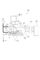
図1は、第1実施形態に係るレーザ加工装置の構成を示す斜視図である。図1に示すように、レーザ加工装置1000は、加工機100と、搬送機200と、を備えている。搬送機200は、加工機100にワークWを搬送する。加工機100は、搬送されたワークWをレーザ加工(アブレーション加工)する。第1実施形態では、ワークWは、平板状の部材(ウェハ)である。
[First Embodiment]
FIG. 1 is a perspective view showing the configuration of the laser processing apparatus according to the first embodiment. As shown in FIG. 1, the
加工機100は、複数のワークW(第1実施形態では2つのワークW)を同時に加工するものである。ここで、加工機100におけるワークWが搬送される面(後述するワークチャック115L,115Rの面)に対して水平な方向であって互いに交差(直交)する2方向をX軸方向、Y軸方向とし、垂直な方向をZ軸方向とする。
The
加工機100は、架台101、除振台102及び定盤103を有する。架台101は、床上に設置されている。架台101上には、除振台102が載置され、除振台102には、定盤103が載置されている。除振台102は、架台101を介し床から定盤103に伝わる振動を減衰させる。定盤103は、高い剛性を有し、定盤103上に搭載されるユニットに安定した面を提供する。なお、除振台102は、ゴムや空気バネなど、振動を減衰し伝達する性質を有したものであれば良く、特に限定するものではない。
The
加工機100は、定盤103の上に搭載された、フレーム104及びXYステージ110を有する。XYステージ110は、複数のワークWを同時にXY軸方向に移動させる移動機構である。XYステージ110は、Y軸ステージガイド111と、Y軸ステージスライダ112と、X軸ステージガイド113と、X軸ステージスライダ114とを有する。
The
X軸ステージスライダ114は、X軸ステージガイド113に搭載され、X軸方向に移動が可能である。X軸ステージガイド113は、Y軸ステージスライダ112に搭載されている。Y軸ステージスライダ112は、Y軸ステージガイド111に搭載され、Y軸方向に移動が可能である。
The
定盤103には、Y軸ステージスライダ112をY軸方向に移動させる不図示の駆動機構(例えば回転モータ、軸継手及びボールねじ)が搭載されている。更に定盤103には、Y軸ステージスライダ112のY軸方向の位置を計測する不図示のスケールが組み込まれている。
On the
Y軸ステージスライダ112には、X軸ステージスライダ114をX軸方向に移動させる不図示の駆動機構(例えば回転モータ、軸継手及びボールねじ)が搭載されている。更にY軸ステージスライダ112には、X軸ステージスライダ114のX軸方向の位置を計測する不図示のスケールが組み込まれている。
The Y-
X軸ステージスライダ114には、複数のワークチャック(保持部)、第1実施形態では、2つのワークチャック、即ちワークチャック115Lとワークチャック115Rとが搭載されている。ワークチャック115L及びワークチャック115Rには、それぞれ不図示の吸着穴が多数設けられており、不図示の内部溝で連通され、不図示の真空発生装置によって発生した負圧空気によって、ワークを真空吸着により保持することが可能である。
On the
各ワークチャック115L,115Rの裏面には、不図示の冷却ジャケットが取り付けられている。冷却ジャケットは、不図示の内部溝を有し、不図示の冷却装置から圧送された冷却液を内部溝に通すことで、ワークチャック115L及びワークチャック115Rを冷却することが可能である。
A cooling jacket (not shown) is attached to the back surface of each
また、各ワークチャック115L,115Rの裏面には、不図示のワークリフタが取り付けられている。ワークリフタは、駆動機構、例えばエアシリンダーを有している。ワークリフタにおける可動側の先端には、不図示のワークリフトピンが搭載されている。ワークチャック115L、ワークチャック115R及び不図示の冷却ジャケットには、それぞれ不図示の貫通穴が設けられている。そのため、ワークリフタによってワークリフトピンをワークチャック115L及びワークチャック115Rのワークチャック面に対して昇降させることが可能である。また、ワークリフトピンには、吸着穴が設けられており、不図示の真空発生装置によって発生した負圧空気によってワークを真空吸着により固定することが可能である。
A work lifter (not shown) is attached to the back surface of each
また、加工機100は、ワークチャック115L,115Rに保持されたワークWを撮像する、精密測定用のカメラ138L,138Rを有する。また、加工機100は、フレーム104の上部に固定された、2つのワークチャック115L,115Rにそれぞれ対応する2つのZステージ130L,130Rを有する。
In addition, the
Zステージ130L(130R)は、Z軸ステージガイド132L(132R)と、Z軸ステージスライダ134L(134R)とを有する。Z軸ステージスライダ134L(134R)は、Z軸ステージガイド132L(132R)に搭載されており、Z軸方向に移動が可能である。
The
Zステージ130L(130R)には、Z軸ステージスライダ134L(134R)をZ軸方向に移動させるための不図示の駆動機構(例えば回転モータ、軸継手及びボールねじ)が搭載されている。さらにZステージ130L(130R)には、Z軸ステージスライダ134L(134R)のZ軸方向の位置を計測する不図示のスケールが組み込まれている。
The
また、加工機100は、複数(第1実施形態では2つ)のレーザ光学系150L,150Rを有する。
Further, the
レーザ光学系150Lは、レーザ光を出射するレーザ発振部であるレーザ発振器144Lと、ガルバノスキャナ140Lと、レーザ光を集光する集光レンズであるfθレンズ142Lと、を有する。レーザ発振器144Lは、不図示の装置カバーに固定されている。レーザ発振器144Lにより出射されたレーザ光は、光ファイバー、コリメータ及び折り返しミラー等の光学系を介してガルバノスキャナ140Lに導かれる。ガルバノスキャナ140Lは、Zステージ130LのZ軸ステージスライダ134Lに取り付けられている。ガルバノスキャナ140Lは、2枚のエンコーダー付きミラーを有し、レーザ光をXY軸方向に走査する。fθレンズ142Lは、ガルバノスキャナ140Lに取り付けられている。fθレンズ142Lを通過し集光されたレーザ光は、ワークチャック115L上に設置されたワークの加工面(表面)に焦点が位置するよう、Zステージ130Lによって焦点距離が調整される。その際にワーク加工面までの距離を、フレーム104に固定された変位計155Lによって測定することで、ワーク毎の厚みバラツキに対応した焦点距離の調整が可能となる。これらガルバノスキャナ140L及びfθレンズ142Lにより、ワークの表面にレーザ光を照射して、ワークを加工するレーザ加工部143Lが構成されている。
The laser
レーザ加工部143L(ガルバノスキャナ140L)の加工可能範囲、つまりレーザ光を走査可能な範囲は矩形状である。レーザ加工部143L(ガルバノスキャナ140L)により実際に加工を行う範囲(加工範囲)、つまりレーザ光を走査する範囲は、加工可能範囲以下であり、第1実施形態では矩形状である。レーザ加工部143Lは、この加工範囲内にレーザ光を照射して加工を行う。
The processable range of the
レーザ光学系150Rについても、レーザ光学系150Lと同様の構成であり、レーザ発振器144Rと、ガルバノスキャナ140R及びfθレンズ142Rで構成されたレーザ加工部143Rとを有する。fθレンズ142Rを通過し集光されたレーザ光は、ワークチャック115R上に設置されたワークの加工面(表面)に焦点が位置するよう、Zステージ130Rによって焦点距離が調整される。その際にワーク加工面までの距離を、フレーム104に固定した変位計155Rによって測定することで、ワーク毎の厚みバラツキに対応した焦点距離の調整が可能となる。
The laser
以上の構成によりXYステージ110は、ワークチャック115L,115Rをガルバノスキャナ140L,140Rに対して移動させることで、ワークチャック115L,115Rとレーザ加工部143L,143Rとを相対的に移動させることができる。つまりXYステージ110は、各レーザ加工部143L,143Rの加工範囲を、各ワークチャック115L,115R(つまり、各ワーク)に対して同時に同じ方向に同じ量、相対的に移動させることができる。
With the above configuration, the
なお、レーザ加工部143L,143Rに対してワークチャック115L,115Rを移動させる構成としたが、ワークチャック115L,115Rとレーザ加工部143L,143Rとが相対的に移動すればよい。したがって、移動機構により、ワークチャック115L,115Rに対してレーザ加工部143L,143Rを移動させる構成としてもよいし、両者を移動させる構成としてもよい。また、2つのレーザ発振器144L,144Rにて発振したレーザ光をレーザ加工部143L,143Rに導く場合について説明したが、1つのレーザ発振器で発振したレーザ光を、各レーザ加工部143L,143Rに導くように構成してもよい。
In addition, although it was set as the structure which moves the work chuck |
以上、第1実施形態では、各ワークチャック115L,115R上に搬送された各ワークWに対し、各レーザ発振器から出射されたレーザ光をfθレンズで集光し、エネルギーをワーク上の加工点に集中させて、ワークを瞬時に溶融・蒸発させて加工を行う。またXYステージ110による各ワークチャック115L,115R上のワークWの粗位置決めと各レーザ加工部143L,143Rによる各レーザ光の細位置決めを繰り返すことで、大径ワークに対し高精度な加工を可能にしている。つまり、ガルバノスキャナ140L,140Rによる狭範囲の高速加工と、XYステージ110によるステップ移動の組み合わせにより、広範囲の加工可能を可能にしている。なお、第1実施形態では、2つのワークを同時に加工する場合について述べているが、1つのワーク単体を加工することも可能である。
As described above, in the first embodiment, the laser beam emitted from each laser oscillator is condensed by the fθ lens on each workpiece W conveyed on each
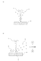
ここで、レーザ光によりアブレーション加工を行う際に発生するデブリについて説明する。図2(a)は、デブリの飛散の様子を説明するための図、図2(b)は、デブリを除去する様子を説明するための図である。 Here, debris generated when ablation processing is performed with laser light will be described. FIG. 2A is a diagram for explaining how debris is scattered, and FIG. 2B is a diagram for explaining how debris is removed.
アブレーション加工を行うレーザ加工装置では、図2(a)に示すように、加工時にデブリDとよばれる微小な加工屑が飛散し、これがレーザ光Lを遮蔽したり、ワークWに付着したりすると加工精度が低下するという問題が存在する。このため、図2(b)に示すように、デブリDをエアAでレーザ光路上から除去する必要がある。また、デブリDがレーザ光Lを遮蔽することによる加工精度の低下を効果的に抑制するためには、図2(b)に示すように、レーザ密度の高い加工点Pの近傍に強いエアAを供給し、デブリDをレーザ光路上から除去することが有効である。 In a laser processing apparatus that performs ablation processing, as shown in FIG. 2 (a), when minute processing scraps called debris D are scattered during processing, this shields the laser beam L or adheres to the workpiece W. There is a problem that processing accuracy is lowered. For this reason, it is necessary to remove the debris D from the laser beam path with air A as shown in FIG. Further, in order to effectively suppress a decrease in processing accuracy due to the debris D shielding the laser light L, as shown in FIG. 2B, strong air A is provided in the vicinity of the processing point P having a high laser density. It is effective to remove the debris D from the laser beam path.
第1実施形態では、図1に示すように、加工機100は、複数(第1実施形態では2つ)のデブリ回収装置160L,160Rを有する。
In the first embodiment, as illustrated in FIG. 1, the
ここで、比較例のデブリ回収装置について説明する。図12は、比較例のデブリ回収装置を示す模式図である。デブリ回収装置160Xは、デブリ回収機構170Xと、送風機180Xと、集塵機190Xと、を有する。デブリ回収機構170Xは、ダクト300Xと、噴出部材400Xとを有する。
Here, the debris collection apparatus of the comparative example will be described. FIG. 12 is a schematic view showing a debris collection device of a comparative example. The
噴出部材400Xは、ダクト300Xに取り付けられ、送風機180Xに接続管181Xを介して接続されている。これにより、噴出部材400Xは、送風機180Xから送風されたエアをダクト300Xの内部に噴出する。
The
ダクト300Xの天部301X及び底部302Xには、レーザ光Lが通過する開口部311X,312Xが形成されている。また、ダクト300Xにおいて噴出部材400Xに対向する部分には、集塵機190Xにフレキシブルホース191Xを介して接続される吸引口310Xが形成されている。集塵機190Xを動作させることにより、吸引口310Xからは、ダクト300X内のエア及びデブリが吸引される。
ここで、集塵機190Xによるエアの吸引により、ダクト300Xの開口部311X,312XからはエアA1X,A2Xがダクト300X内に流入する。このとき、開口部312Xから流入するエアA2Xにより、噴出部材400XからのエアB1Xの流れが妨げられる。これにより、デブリをレーザ光路上から十分に除去できなくなる。ダクト300X内の上部に飛散したデブリは、天部301Xの開口部311Xから流入したエアA1Xの流れに乗り、ダクト300X内をレーザ光を遮蔽しながら対流して吸引口310Xを介して集塵機190Xに回収される。このように、デブリがレーザ光を遮蔽することによって、加工精度が大きく低下する。
Here, the air A1X and A2X flow into the
第1実施形態のデブリ回収装置160L,160Rについて説明する。図3は、第1実施形態におけるデブリ回収装置を示す模式図である。以下、デブリ回収装置160Lとデブリ回収装置160Rとは同一の構成であるため、デブリ回収装置160として説明する。また、レーザ加工部143Lとレーザ加工部143Rも同一の構成であるため、レーザ加工部143(ガルバノスキャナ140及びfθレンズ142)として説明する。図3において、ワークWは、ワークチャック115L,115Rに固定されている状態を示している。
デブリ回収装置160は、デブリ回収機構170と、送風機180と、集塵機190と、を有する。デブリ回収機構170は、ダクト300と、噴出部材400とを有する。デブリ回収機構170(即ち、ダクト300)は、フレーム104(図1)に固定されている。ダクト300は、箱形状に形成されている。
The
なお、第1実施形態では、2つのデブリ回収機構それぞれに対して個別に送風機180を設けているが、2つのデブリ回収機構で1つの送風機を共有してもよい。同様に、2つのデブリ回収機構それぞれに対して個別に集塵機190を設けているが、2つのデブリ回収機構で1つの集塵機を共有してもよい。
In the first embodiment, the
送風機180は、高圧の気体(エア)を送風するものである。集塵機190は、塵等を吸引する吸引装置であり、気体(エア)と共に塵を吸引する。なお、送風機180は、空気以外の気体を送風するように構成されていてもよい。
The
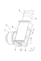
図4及び図5は、第1実施形態におけるデブリ回収機構を示す斜視図である。ダクト300は、天部301、天部301に間隔をあけて対向する底部302、及び天部301と底部302とを接続する側部303を有する。天部301、底部302及び側部303で囲まれて、ダクト300の内部空間が形成される。ダクト300の内部空間は、天部301から底部302に向かって先細る台形状に形成されている。
4 and 5 are perspective views showing the debris collection mechanism in the first embodiment. The
ダクト300は、図3に示すように、天部301がレーザ加工部143のfθレンズ142に対向し、且つ底部302がワークチャックに搬送されたワークWの表面に対向するよう、fθレンズ142とワークW(ワークチャック)との間に配置される。
As shown in FIG. 3, the
噴出部材400は、ダクト300の側部303の一部分(一側面)に取り付けられ、送風機180に接続管181を介して接続されている。これにより、噴出部材400は、送風機180から送風されたエアをダクト300の内部に噴出する。
The
天部301には、fθレンズ142を通過したレーザ光が通過する開口部(第1開口部)311が形成されている。底部302には、fθレンズ142を通過したレーザ光が通過する開口部(第2開口部)312が形成されている。図4及び図5中、領域Rは、底部302(開口部312)においてレーザ光が通過する領域である。開口部312は、レーザ光が通過する領域Rよりも僅かに(例えば1辺の長さが1mm程度)大きく形成されている。
The
ダクト300の側部303において、噴出部材400に対して領域Rよりも遠い部分、第1実施形態では噴出部材400に対向する部分(他側面)には、吸引口310が形成されている。吸引口310には、フレキシブルホース191を接続するフランジ320が取り付けられている。したがって、吸引口310は、フランジ320及びフレキシブルホース191を介して集塵機190に接続されている。集塵機190を動作させることにより、吸引口310からは、ダクト300内のエア及びデブリが吸引される。即ち、吸引口310においては、集塵機190に吸引されるダクト300の内部の気体及びデブリが通過する。
In the
側部303(一側面)において、噴出部材400に対して天部301に近い側の部分には、開口部(第3開口部)313が形成されている。具体的に説明すると、側部303の開口の一部を塞ぐように噴出部材400を側部303に配置(固定)することにより、開口の残りの部分で開口部313が形成される。
In the side portion 303 (one side surface), an opening (third opening) 313 is formed in a portion closer to the
ここで、Z軸方向は、天部301から底部302に向かう方向(つまり、天部301又は底部302に対して垂直な方向)でもあり、ワークWにレーザ光を照射する方向でもある。XY軸方向は、天部301又は底部302に水平な方向でもあり、レーザ光の照射方向と直交する方向でもある。このXY軸方向のうち、Y軸方向は、開口部313から吸引口310に向かう方向であり、X軸方向は、このY軸方向に直交する方向である。
Here, the Z-axis direction is also a direction from the top 301 to the bottom 302 (that is, a direction perpendicular to the top 301 or the bottom 302), and is also a direction in which the workpiece W is irradiated with laser light. The XY axis direction is also a direction horizontal to the
噴出部材400は、底部302に沿ってエアB1を噴出するように、側部303においてZ軸方向の中央よりも底部302に近い側、第1実施形態では底部302に接して配置されている。
The
図3に示すように、ダクト300の内部には、集塵機190により開口部311,312,313からエアA1,A2,A3が流入する。第1実施形態では、集塵機190の動作によりダクト300内に流入するエアのうち大半が、開口部313から流入するエアA3である。
As shown in FIG. 3, air A <b> 1, A <b> 2, A <b> 3 flows into the
また、開口部312から流入するエアA2の流量は、噴出部材400から噴出されるエアB1がエアカーテンとなり、極めて小さい。なお、開口部311から流入するエアA1の流量は、開口部312から流入するエアA2の流量よりも多い。
Further, the flow rate of the air A2 flowing from the
エアB1は、開口部312から流入するエアA2に妨げられることなく、方向及び流速を保ちながら、加工点Pの近傍を流れる。これにより、デブリはレーザ密度の高い加工点Pの近傍でレーザ光路上から除去される。また、ダクト300の内部に流入するエアは、開口部313から流入するエアA3が流量の大半占める。したがって、開口部311から流入するエアA1は、エアA3に巻き込まれ、吸引口310へ向かうY軸方向に整流化された流れとなる。
The air B1 flows in the vicinity of the machining point P while maintaining the direction and the flow velocity without being blocked by the air A2 flowing in from the
以上、第1実施形態によれば、噴出部材400により、加工点Pの近傍に強いエアB1を吹くことができる。さらに、開口部313から流入するエアA3により、ダクト300の内部には、開口部313から吸引口310に向かう整流化されたエアの流れを作り出すことができる。
As described above, according to the first embodiment, the blowing
よって、レーザ密度の高い加工点Pの近傍でレーザ光路上からデブリを除去し、レーザ光Lを遮蔽することなく集塵機190によりデブリを回収することができる。更に、デブリをワークに付着させることなく確実に回収することが可能となる。したがって、デブリによる加工精度の低下を大幅に抑制することができる。
Therefore, debris can be removed from the laser beam path in the vicinity of the processing point P having a high laser density, and the debris can be collected by the
ここで、ダクト300は、ワークWと非接触状態でワークWとの隙間がなるべく小さくなるよう配置されている。これにより、ダクト300の振動がワークWに伝搬するのを防止しながらも、噴出部材400から噴出させたエアB1を、ワークWの加工点Pの近傍に流すことができる。
Here, the
ダクト300のZ軸方向の高さは、なるべく高くするのがよい。これにより、デブリが開口部311からダクト300の外に飛散するのを抑制することができる。
The height of the
また、開口部311及び開口部312は、レーザ光Lの通過を遮らない面積を確保したうえで、なるべく小さく形成されている。集塵機190の吸引動作により開口部311,312からダクト300内に流入するエアA1,A2の流量を少なくしている。
In addition, the
一方、開口部313は、開口部311よりも開口面積が大きく形成されている。集塵機190の吸引動作により開口部313からダクト300内に流入するエアA3の流量を多くしている。したがって、集塵機190によりダクト300内に流入するエアの大半を開口部313から取り込むことが可能となる。
On the other hand, the
開口部313は、図4及び図5に示すように、ダクト300の内部空間に倣い、底部302に近い側の辺が天部301に近い側の辺より短い台形状に形成されている。これにより、開口部313の開口形状をレーザ集光形状に合わせたことになり、底部302側のダクト300内のエアの流速を速めることができる。ダクト300内のエアの流速を速めたことにより、デブリの回収能力が向上する。
As shown in FIGS. 4 and 5, the
図6は、第1実施形態における噴出部材を示す斜視図である。図6に示すように、噴出部材400には、エアを噴き出すノズル口401が複数(第1実施形態では16個)形成されている。これら複数のノズル口401は、Z軸方向に多段配置(第1実施形態では4段配置)され、X軸方向に多列配置(第1実施形態では4列配置)されている。
FIG. 6 is a perspective view showing the ejection member in the first embodiment. As shown in FIG. 6, the
第1実施形態では、1つの大きなノズル口とせず、複数のノズル口401とすることにより、各ノズル口401から噴出されるエアの風速を高めている。また、多段配置された複数のノズル口401のうち、最下段のノズル口401から噴出されるエアは、ダクト300の底部302に沿って流れることとなり、開口部312にY軸方向の強風のエアを吹き付けることができる。また、ノズル口401をX軸方向の多列配置としたことで、レーザ加工部143によるレーザ走査範囲全域にエアを流すことができる。
In the first embodiment, a plurality of
[第2実施形態]
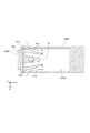
次に、第2実施形態に係るレーザ加工装置について説明する。図7は、第2実施形態におけるデブリ回収装置を示す模式図である。図8及び図9は、第2実施形態におけるデブリ回収機構を示す斜視図である。なお、第2実施形態において、第1実施形態と同様の構成については、同一符号を付して説明を省略する。第2実施形態では、ダクトの底部において第2開口部を大きく開けて、噴出部材により噴出させた気体をワークの表面に吹き付ける構造としたものである。以下、具体的に説明する。
[Second Embodiment]
Next, a laser processing apparatus according to the second embodiment will be described. FIG. 7 is a schematic diagram illustrating a debris collection device according to the second embodiment. 8 and 9 are perspective views showing a debris collection mechanism in the second embodiment. Note that in the second embodiment, identical symbols are assigned to configurations similar to those in the first embodiment and descriptions thereof are omitted. In the second embodiment, the second opening is greatly opened at the bottom of the duct, and the gas jetted by the jetting member is blown onto the surface of the workpiece. This will be specifically described below.
デブリ回収装置160Aは、デブリ回収機構170Aと、送風機180Aと、集塵機190Aと、を有する。デブリ回収機構170Aは、ダクト300Aと、噴出部材400Aとを有する。デブリ回収機構170A(即ち、ダクト300A)は、フレーム104(図1参照)に固定されている。ダクト300Aは箱形状に形成されている。
The
なお、第2実施形態では、2つのデブリ回収機構それぞれに対して個別に送風機180Aを設けているが、2つのデブリ回収機構で1つの送風機を共有してもよい。同様に、2つのデブリ回収機構それぞれに対して個別に集塵機190Aを設けているが、2つのデブリ回収機構で1つの集塵機を共有してもよい。
In the second embodiment, the
送風機180Aは、高圧の気体(エア)を送風するものである。集塵機190Aは、塵等を吸引する吸引装置であり、気体(エア)と共に塵を吸引する。なお、送風機180Aは、空気以外の気体を送風するように構成されていてもよい。
The
ダクト300Aは、天部301A、天部301Aに間隔をあけて対向する底部302A、及び天部301Aと底部302Aとを接続する側部303Aを有する。天部301A、底部302A及び側部303Aで囲まれて、ダクト300Aの内部空間が形成される。
The
ダクト300Aは、天部301Aがレーザ加工部143のfθレンズ142に対向し、且つ底部302Aがワークチャックに搬送されたワークWの表面(加工面)に対向するよう、fθレンズ142AとワークW(ワークチャック)との間に配置される。
The
噴出部材400Aは、ダクト300Aの側部303Aの一部分(一側面)に取り付けられ、送風機180Aに接続管181Aを介して接続されている。これにより、噴出部材400Aは、送風機180Aから送風された気体(エア)をダクト300Aの内部に噴出する。
The
天部301Aには、fθレンズ142を通過したレーザ光が通過する開口部(第1開口部)311Aが形成されている。底部302Aには、fθレンズ142を通過したレーザ光が通過する開口部(第2開口部)312Aが形成されている。図9中、領域Rは、底部302A(開口部312A)においてレーザ光が通過する領域である。
The top 301A is formed with an opening (first opening) 311A through which the laser light that has passed through the
ダクト300Aの側部303Aにおいて、噴出部材400Aに対して領域Rよりも遠い部分、第2実施形態では噴出部材400Aに対向する部分(他側面)には、吸引口310Aが形成されている。吸引口310Aには、フレキシブルホース191Aを接続するフランジ320Aが取り付けられている。したがって、吸引口310Aは、フランジ320A及びフレキシブルホース191Aを介して集塵機190Aに接続されている。集塵機190Aを動作させることにより、吸引口310Aからは、ダクト300A内のエア及びデブリが吸引される。即ち、吸引口310Aにおいては、集塵機190Aに吸引されるダクト300Aの内部の気体及びデブリが通過する。
In the
側部303A(一側面)において、噴出部材400Aに対して天部301Aに近い側の部分には、開口部(第3開口部)313Aが形成されている。
In the
噴出部材400Aは、底部302Aに沿ってエアを噴出するように、側部303AにおいてZ軸方向の中央よりも底部302Aに近い側、第2実施形態では底部302Aに接して配置されている。
The
第2実施形態では、デブリ回収機構170Aは、補助噴出部材410Aと、調整部材であるパンチングメタル420Aとを更に有している。
In the second embodiment, the
補助噴出部材410Aは、接続管181Aで送風機180Aに接続されている。補助噴出部材410Aは、側部303A(一側面)において開口部313Aに対して天部301Aに近い側の部分に配置され、送風機180Aから送風された気体をダクト300Aの内部に噴出する。補助噴出部材410Aは、天部301Aに沿ってエアを噴出するように、側部303AにおいてZ軸方向の中央よりも天部301Aに近い側、第2実施形態では天部301Aに接して配置されている。
The
なお、補助噴出部材410Aは、送風機180Aに接続される場合について説明したが、送風機180Aとは別の送風機(不図示)に接続されて、噴出部材400Aとは独立してエアを噴出するようにしてもよい。
In addition, although the auxiliary |
パンチングメタル420Aは、開口部313Aに配置され、通気量を調整する部材である。つまり、パンチングメタル420Aにより、開口部313Aにおける開口率が制限される。なお、調整部材はパンチングメタル420Aに限定するものではなく、フィルタやグレーチング、メッシュなどでも良く、開口率を制限(調整)できるものであれば特に制限するものではない。
The punching
開口部312Aは、底部302Aにおいて、レーザ光が通過する領域Rから噴出部材400Aに向かって開口するように形成されている。具体的には、開口部312Aは、Y軸方向において、領域Rと噴出部材400Aとの間の中央地点よりも噴出部材400側に延びるように開口して形成されている。
The
第2実施形態では、開口部312Aは、噴出部材400Aまで開口して形成されている。したがって、開口部312Aは、少なくとも図9中の一点鎖線で示す領域R1を包含して形成されている。
In the second embodiment, the
更に、開口部312Aは、底部302Aにおいて、領域Rから吸引口310Aに向かって開口するように形成されている。具体的には、開口部312Aは、Y軸方向において、領域Rと吸引口310Aとの間の中央地点よりも吸引口310A側に延びるように開口して形成されている。第2実施形態では、開口部312Aは、吸引口310Aまで開口して形成されている。即ち、開口部312Aは、底部302Aの全体が開口するように形成されている。
Furthermore, the
図10(a)は、第2実施形態における噴出部材を示す斜視図である。図10(b)は、第2実施形態における噴出部材を示す中央断面図である。図10(a)に示すように、噴出部材400Aには、複数のノズル口401A,402Aが形成されている。第2実施形態では第1ノズル口であるノズル口401Aは、16個形成され、第2ノズル口であるノズル口402Aは、4個形成されている。
Fig.10 (a) is a perspective view which shows the ejection member in 2nd Embodiment. FIG. 10B is a central sectional view showing the ejection member in the second embodiment. As shown in FIG. 10A, a plurality of
ノズル口401Aは、Z軸方向に多段配置されている。ノズル口402Aは、Z軸方向に1段だけ配置されており、Z軸方向において、ノズル口401Aの最下段と同じ位置に形成されている。即ち、ノズル口402Aは、複数のノズル口のうち少なくとも底部302Aに最も近い段に位置するように形成されている。なお、ノズル口402Aについても、ノズル口401Aと同様、多段配置してもよい。
The
また、ノズル口401Aは、X軸方向に多列配置(例えば4列配置)されている。ノズル口402Aについては、複数のノズル口401AのX軸方向の両側に配置されており、各々の位置でX軸方向に多列配置(例えば2列配置)されている。
Further, the
図10(b)に示すように、噴出部材400Aの内部は中空構造となっている。そして、ノズル口401Aと対応する面に設けられた給気穴415Aから高圧のエアが供給されることで各ノズル口401A,402Aからエアを噴出する。
As shown in FIG. 10B, the inside of the
複数のノズル口401A,402Aのうち、少なくとも底部302Aに最も近い段に位置するノズル口401Aは、底部302Aに向かってガスを噴き出すよう傾斜して形成されている。なお、図示は省略するが、ノズル口402Aについても、底部302Aに向かってガスを噴き出すよう傾斜して形成されている。第2実施形態では最下段以外の段についてもノズル口401Aが傾斜して形成されている。そして、下段のノズル口ほど勾配が大きくなっている。
Of the plurality of
第2実施形態においても、ダクト300Aは、ワークWと非接触状態でワークWとの隙間がなるべく小さくなるよう配置されている。これにより、ダクト300Aの振動がワークWに伝搬するのが防止される。
Also in the second embodiment, the
ここで、図8に示すように、ワークWの周囲には、ワークWの表面(加工面)と同じ高さとなる板部材(同面板)118AがXYステージ110上に設置される。この同面板118Aは、レーザ加工時にワークWをXYステージ110で移動させても、開口部312Aの全てがワークWおよび同面板118A上に位置する面積を有するように形成されている。これにより、ダクト300Aの内部に吸い込まれる気流が安定する。
Here, as shown in FIG. 8, a plate member (same surface plate) 118 </ b> A having the same height as the surface (working surface) of the workpiece W is installed on the
図11は、第2実施形態におけるダクト300Aの底部302Aの位置で、天部301Aから底部302Aに向かう方向に見た、エアA12,B11,B12の流れを示す説明図である。
FIG. 11 is an explanatory diagram illustrating the flow of air A12, B11, and B12 at the position of the
ノズル口401A(図10(a))からは、図11に示すように、エアB11が噴出され、ノズル口402A(図10(a))からは、エアB12が噴出される。Z軸方向に見て、ノズル口401Aは、加工範囲(走査範囲)に対応する領域Rに向かってガスを噴き出すように配置されている。また、ノズル口402Aは、Z軸方向に見て、領域RのX軸方向の側方の領域に向かってガスを噴き出すように配置されている。したがって、領域Rにはノズル口401Aから噴き出された高速のエアB11が流れる。
As shown in FIG. 11, air B11 is ejected from the
図11中の破線は、エアB11の風速分布を表したものであり、この分布のようにエアB11は中央の風速が速くなる。なお、噴出部材400Aのノズル口401Aは、領域(走査範囲上)Rに所望の風速を流せるようX軸方向のノズル口数、ノズル口間隔、噴出部材400Aに供給するエア圧力等を決定する。
The broken line in FIG. 11 represents the wind speed distribution of the air B11, and the wind speed at the center of the air B11 becomes faster like this distribution. The
噴出部材400Aの両端に位置するノズル口402Aから噴き出されるエアB12は、開口部312Aからダクト300Aの内部に流入するエアA12がエアB11の流れを妨げるのを防ぐ役割を果たしている。なお、エアB12はエアA12の流れに押されダクト300Aの内向きに流れ、ダクト300Aの外に漏れることがないよう、ノズル位置や噴出部材400Aに供給するエア圧力等を決定する。これにより、デブリはダクト300Aの外に漏れず、ワークWに付着することなく回収することが可能となる。
The air B12 ejected from the
続いて、ダクト300AのX軸方向中心を通るYZ平面上のエア流れについて説明する。図10(a)に示すノズル口401Aから噴き出された高速のエアB11は、図7に示すように、ワークWの表面に沿ってY軸方向に流れて、加工点Pの近傍を流れる。エアB11は、加工点Pのエア吹付方向下流で開口部312Aの奥側からダクト内に流入するエアA15に持ち上げられ、ダクト300A内に流れる。
Subsequently, the air flow on the YZ plane passing through the center of the
これによりデブリはダクト300Aの外に漏れず、ワークWに付着することなく回収することが可能となる。なお、エアA15は、集塵機190Aがダクト300A内のエアを排気する際、ダクト300A内に流入するエアである。
As a result, the debris does not leak out of the
加工点Pの近傍に所望の風速を流せるように、噴出部材400AにおけるZ軸方向のノズル口数、ノズル口間隔、噴出部材400Aに供給するエア圧力、図10(b)に示すノズル口401Aの下向き傾斜角度等が決定されている。
In order to allow a desired wind speed to flow in the vicinity of the processing point P, the number of nozzle ports in the Z-axis direction of the
開口部312AのY軸方向の奥側にてエアB11の流れがエアA15の流れよりも強くダクト300Aの外に漏れる場合は、開口部312Aの奥行きを広げ、エアA15と衝突する位置をエア吹出方向下流にシフトさせることで流れを改善することができる。
When the flow of the air B11 is stronger than the flow of the air A15 at the back side in the Y axis direction of the
また、パンチングメタル420Aにより開口部313Aの開口率を下げ、ダクト300Aの前面からダクト300Aの内部に流入するエアA13の流量を下げることで、エアA15の流量を上げ、流れを改善することもできる。
Further, the opening ratio of the
同様に、補助噴出部材410Aから噴き出されるエアB21を開口部311Aのエアカーテンとして機能させ、天部301Aからダクト300Aの内部に流入するエアA11の流量を下げることでエアA15の流量を上げ、流れを改善することもできる。
Similarly, the air B21 ejected from the
なお、この際、エアA21がダクト300Aの外部に漏れないよう、風速等が設定されている。加工点Pの近傍に所望の風速のエアを流すことができ、エアB11が開口部312の奥からダクト300Aの外に漏れない流れを作り出せれば、パンチングメタル420A及び補助噴出部材410Aはなくても構わない。
At this time, the wind speed and the like are set so that the air A21 does not leak outside the
以上、第2実施形態のデブリ回収機構170Aによれば、ワークW上に高速のエアを流すことができるため、レーザ密度の高い加工点Pの近傍でデブリをレーザ光路上から除去することができる。また、デブリをダクト300Aの内部に閉じ込めて、デブリがワークWに付着するのを抑制しながら、デブリを回収することができる。ゆえに、デブリによる加工精度の低下を大幅に抑えることが可能となる。
As described above, according to the
なお、本発明は、以上説明した実施形態に限定されるものではなく、本発明の技術的思想内で多くの変形が可能である。また、本発明の実施形態に記載された効果は、本発明から生じる最も好適な効果を列挙したに過ぎず、本発明による効果は、本発明の実施形態に記載されたものに限定されない。 The present invention is not limited to the embodiment described above, and many modifications are possible within the technical idea of the present invention. In addition, the effects described in the embodiments of the present invention only list the most preferable effects resulting from the present invention, and the effects of the present invention are not limited to those described in the embodiments of the present invention.
上述の実施形態では、レーザ加工装置が送風機及び集塵機を備えている場合について説明したが、これに限定するものではなく、レーザ加工装置に送風機及び集塵機を接続するように構成されていてもよい。 In the above-described embodiment, the case where the laser processing apparatus includes the blower and the dust collector has been described. However, the present invention is not limited to this, and the laser processing apparatus may be configured to connect the blower and the dust collector.
また、上述の実施形態では、レーザ加工部143がスキャン光学系を採用した場合(即ち、ガルバノスキャナを有する場合)について説明したが、スキャン光学系を採用しない場合であってもよい。
In the above-described embodiment, the case where the
143…レーザ加工部、170…デブリ回収機構、180…送風機、190…集塵機、300…ダクト、301…天部、302…底部、303…側部、310…吸引口、311…開口部(第1開口部)、312…開口部(第2開口部)、313…開口部(第3開口部)、400…噴出部材、1000…レーザ加工装置 143 ... Laser processing part, 170 ... Debris collection mechanism, 180 ... Blower, 190 ... Dust collector, 300 ... Duct, 301 ... Top part, 302 ... Bottom part, 303 ... Side part, 310 ... Suction port, 311 ... Opening part (first (Opening), 312 ... opening (second opening), 313 ... opening (third opening), 400 ... jetting member, 1000 ... laser processing apparatus
Claims (13)
前記ダクトの側部に配置され、送風機から送風された気体を前記ダクトの内部に噴出する噴出部材と、を有し、
前記ダクトには、
前記レーザ加工部に対向する天部に、前記レーザ光が通過する第1開口部と、
前記ワークの表面に対向する底部に、前記レーザ光が通過する第2開口部と、
前記側部において、前記噴出部材に対し、前記第2開口部における前記レーザ光が通過する領域よりも遠い部分に、集塵機に接続され、前記集塵機に吸引される前記ダクトの内部の気体及びデブリが通過する吸引口と、
前記側部において前記噴出部材に対して前記天部に近い側の部分に第3開口部と、が形成されているデブリ回収機構。 A duct disposed between the surface of the workpiece and a laser processing portion that processes the workpiece by irradiating the surface of the workpiece with laser light;
An ejection member that is disposed on a side of the duct and ejects gas blown from a blower into the duct;
In the duct,
A first opening through which the laser beam passes in a top portion facing the laser processing portion;
A second opening through which the laser beam passes, at the bottom facing the surface of the workpiece;
In the side portion, the gas and debris in the duct connected to the dust collector and sucked into the dust collector are connected to the dust collector at a portion farther than the region through which the laser light passes in the second opening with respect to the ejection member. A suction port passing through,
A debris collection mechanism in which a third opening is formed in a portion of the side portion closer to the top portion than the ejection member.
レーザ光を前記ワークの表面に照射して、前記ワークを加工するレーザ加工部と、を備えたレーザ加工装置。 The debris collection mechanism according to any one of claims 1 to 11,
A laser processing apparatus comprising: a laser processing unit configured to irradiate a surface of the work with laser light to process the work.
Priority Applications (1)
| Application Number | Priority Date | Filing Date | Title |
|---|---|---|---|
| JP2015236520A JP6700755B2 (en) | 2015-12-03 | 2015-12-03 | Debris collection mechanism, laser processing apparatus, and article manufacturing method |
Applications Claiming Priority (1)
| Application Number | Priority Date | Filing Date | Title |
|---|---|---|---|
| JP2015236520A JP6700755B2 (en) | 2015-12-03 | 2015-12-03 | Debris collection mechanism, laser processing apparatus, and article manufacturing method |
Publications (3)
| Publication Number | Publication Date |
|---|---|
| JP2017100170A true JP2017100170A (en) | 2017-06-08 |
| JP2017100170A5 JP2017100170A5 (en) | 2019-01-17 |
| JP6700755B2 JP6700755B2 (en) | 2020-05-27 |
Family
ID=59016247
Family Applications (1)
| Application Number | Title | Priority Date | Filing Date |
|---|---|---|---|
| JP2015236520A Active JP6700755B2 (en) | 2015-12-03 | 2015-12-03 | Debris collection mechanism, laser processing apparatus, and article manufacturing method |
Country Status (1)
| Country | Link |
|---|---|
| JP (1) | JP6700755B2 (en) |
Cited By (12)
| Publication number | Priority date | Publication date | Assignee | Title |
|---|---|---|---|---|
| CN107598369A (en) * | 2017-10-20 | 2018-01-19 | 大族激光科技产业集团股份有限公司 | A kind of dust arrester, process equipment and dust removal method using the dust arrester |
| CN108637483A (en) * | 2018-03-13 | 2018-10-12 | 武汉吉事达科技股份有限公司 | A kind of etching laser machining integrated dedusting device |
| JP2019042767A (en) * | 2017-09-01 | 2019-03-22 | 東芝機械株式会社 | Laser processing device and laser processing method |
| KR20190105842A (en) * | 2018-03-06 | 2019-09-18 | 주식회사 새한산업 | Length changeable type laser spot welding apparatus |
| JP2021010923A (en) * | 2019-07-05 | 2021-02-04 | 株式会社デンソー | Laser processing apparatus |
| US20210362270A1 (en) * | 2020-05-20 | 2021-11-25 | G.C. Laser Systems, Inc. | Laser Ablation and Laser Processing Fume and Contaminant Capture System |
| CN114749791A (en) * | 2022-05-13 | 2022-07-15 | 武汉智迅创源科技发展股份有限公司 | Laser engraving machine capable of collecting dust and dust cleaning method |
| KR20230060977A (en) * | 2021-10-28 | 2023-05-08 | 한국원자력연구원 | Laser Scabbling Head and Robot comprising it |
| CN116441820A (en) * | 2023-03-16 | 2023-07-18 | 江苏保均新材科技有限公司 | Welding table for photovoltaic circuit board frame |
| JP7397848B2 (en) | 2018-08-06 | 2023-12-13 | ヴァルカンフォームズ インコーポレイテッド | Additive manufacturing system using gas flow head |
| JP7431601B2 (en) | 2020-02-10 | 2024-02-15 | 株式会社ディスコ | laser processing equipment |
| US11904407B2 (en) | 2019-11-13 | 2024-02-20 | Fanuc Corporation | Laser welding apparatus |
Citations (6)
| Publication number | Priority date | Publication date | Assignee | Title |
|---|---|---|---|---|
| JPH06285668A (en) * | 1993-04-02 | 1994-10-11 | Internatl Business Mach Corp <Ibm> | Protective device for laser processing assembly |
| JPH09141482A (en) * | 1995-11-22 | 1997-06-03 | Mazda Motor Corp | Laser beam machine |
| JP2000317670A (en) * | 1999-05-10 | 2000-11-21 | Matsushita Electric Ind Co Ltd | Dust collecting device, dust collecting method, laser beam machining device and laser beam machining method |
| JP2005262221A (en) * | 2004-03-16 | 2005-09-29 | Denso Corp | Laser beam machining apparatus |
| JP3143457U (en) * | 2008-05-12 | 2008-07-24 | 日立造船株式会社 | Dust collector for laser processing machine |
| JP2014200842A (en) * | 2013-04-10 | 2014-10-27 | 株式会社ディスコ | Laser processing device |
-
2015
- 2015-12-03 JP JP2015236520A patent/JP6700755B2/en active Active
Patent Citations (6)
| Publication number | Priority date | Publication date | Assignee | Title |
|---|---|---|---|---|
| JPH06285668A (en) * | 1993-04-02 | 1994-10-11 | Internatl Business Mach Corp <Ibm> | Protective device for laser processing assembly |
| JPH09141482A (en) * | 1995-11-22 | 1997-06-03 | Mazda Motor Corp | Laser beam machine |
| JP2000317670A (en) * | 1999-05-10 | 2000-11-21 | Matsushita Electric Ind Co Ltd | Dust collecting device, dust collecting method, laser beam machining device and laser beam machining method |
| JP2005262221A (en) * | 2004-03-16 | 2005-09-29 | Denso Corp | Laser beam machining apparatus |
| JP3143457U (en) * | 2008-05-12 | 2008-07-24 | 日立造船株式会社 | Dust collector for laser processing machine |
| JP2014200842A (en) * | 2013-04-10 | 2014-10-27 | 株式会社ディスコ | Laser processing device |
Cited By (16)
| Publication number | Priority date | Publication date | Assignee | Title |
|---|---|---|---|---|
| JP2019042767A (en) * | 2017-09-01 | 2019-03-22 | 東芝機械株式会社 | Laser processing device and laser processing method |
| CN107598369A (en) * | 2017-10-20 | 2018-01-19 | 大族激光科技产业集团股份有限公司 | A kind of dust arrester, process equipment and dust removal method using the dust arrester |
| KR20190105842A (en) * | 2018-03-06 | 2019-09-18 | 주식회사 새한산업 | Length changeable type laser spot welding apparatus |
| KR102090783B1 (en) * | 2018-03-06 | 2020-03-18 | 주식회사 새한산업 | Length changeable type laser spot welding apparatus |
| CN108637483A (en) * | 2018-03-13 | 2018-10-12 | 武汉吉事达科技股份有限公司 | A kind of etching laser machining integrated dedusting device |
| JP7397848B2 (en) | 2018-08-06 | 2023-12-13 | ヴァルカンフォームズ インコーポレイテッド | Additive manufacturing system using gas flow head |
| JP7147700B2 (en) | 2019-07-05 | 2022-10-05 | 株式会社デンソー | Laser processing equipment |
| JP2021010923A (en) * | 2019-07-05 | 2021-02-04 | 株式会社デンソー | Laser processing apparatus |
| US11904407B2 (en) | 2019-11-13 | 2024-02-20 | Fanuc Corporation | Laser welding apparatus |
| JP7431601B2 (en) | 2020-02-10 | 2024-02-15 | 株式会社ディスコ | laser processing equipment |
| US20210362270A1 (en) * | 2020-05-20 | 2021-11-25 | G.C. Laser Systems, Inc. | Laser Ablation and Laser Processing Fume and Contaminant Capture System |
| KR20230060977A (en) * | 2021-10-28 | 2023-05-08 | 한국원자력연구원 | Laser Scabbling Head and Robot comprising it |
| KR102592155B1 (en) * | 2021-10-28 | 2023-10-23 | 한국원자력연구원 | Laser Scabbling Head and Robot comprising it |
| CN114749791A (en) * | 2022-05-13 | 2022-07-15 | 武汉智迅创源科技发展股份有限公司 | Laser engraving machine capable of collecting dust and dust cleaning method |
| CN116441820A (en) * | 2023-03-16 | 2023-07-18 | 江苏保均新材科技有限公司 | Welding table for photovoltaic circuit board frame |
| CN116441820B (en) * | 2023-03-16 | 2023-11-21 | 江苏保均新材科技有限公司 | Welding table for photovoltaic circuit board frame |
Also Published As
| Publication number | Publication date |
|---|---|
| JP6700755B2 (en) | 2020-05-27 |
Similar Documents
| Publication | Publication Date | Title |
|---|---|---|
| JP6700755B2 (en) | Debris collection mechanism, laser processing apparatus, and article manufacturing method | |
| JP6647829B2 (en) | Laser processing equipment | |
| US9259802B2 (en) | Method and apparatus for collecting material produced by processing workpieces | |
| US7326878B2 (en) | Laser beam processing machine | |
| JP5431831B2 (en) | Laser processing equipment | |
| KR102107849B1 (en) | Laser machining apparatus and its intake passage cleaning method | |
| KR102104137B1 (en) | Laser machining apparatus | |
| JP3143457U (en) | Dust collector for laser processing machine | |
| JP5610991B2 (en) | Laser processing equipment | |
| KR20190049985A (en) | Laser apparatus | |
| JP2014104489A (en) | Laser processing device and dust collection method for laser processing device | |
| KR20230085864A (en) | Laser processing apparatus and debris removing apparatus | |
| JP6363894B2 (en) | Laser processing equipment | |
| JP7431601B2 (en) | laser processing equipment | |
| JP2011125871A (en) | Laser beam machining apparatus | |
| JP2013071153A (en) | Laser beam machining apparatus and method | |
| JP2013163216A (en) | Laser beam machining device | |
| JP6061691B2 (en) | Laser processing method and laser processing apparatus | |
| JP5808182B2 (en) | Nozzle cleaner for laser processing equipment | |
| JP2013006200A (en) | Laser machining apparatus | |
| KR20170133931A (en) | Dust cleaner system for laser ablation | |
| JP2004195491A (en) | Laser beam machining apparatus | |
| JP4369764B2 (en) | Mold cleaning device | |
| JP2013043194A (en) | Laser beam machining system and method of manufacturing solar panel | |
| WO2022201528A1 (en) | Laser processing apparatus |
Legal Events
| Date | Code | Title | Description |
|---|---|---|---|
| A521 | Written amendment |
Free format text: JAPANESE INTERMEDIATE CODE: A523 Effective date: 20181129 |
|
| A621 | Written request for application examination |
Free format text: JAPANESE INTERMEDIATE CODE: A621 Effective date: 20181129 |
|
| A977 | Report on retrieval |
Free format text: JAPANESE INTERMEDIATE CODE: A971007 Effective date: 20191023 |
|
| A131 | Notification of reasons for refusal |
Free format text: JAPANESE INTERMEDIATE CODE: A131 Effective date: 20191029 |
|
| A521 | Written amendment |
Free format text: JAPANESE INTERMEDIATE CODE: A523 Effective date: 20191227 |
|
| RD02 | Notification of acceptance of power of attorney |
Free format text: JAPANESE INTERMEDIATE CODE: A7422 Effective date: 20200206 |
|
| RD04 | Notification of resignation of power of attorney |
Free format text: JAPANESE INTERMEDIATE CODE: A7424 Effective date: 20200207 |
|
| TRDD | Decision of grant or rejection written | ||
| A01 | Written decision to grant a patent or to grant a registration (utility model) |
Free format text: JAPANESE INTERMEDIATE CODE: A01 Effective date: 20200317 |
|
| A61 | First payment of annual fees (during grant procedure) |
Free format text: JAPANESE INTERMEDIATE CODE: A61 Effective date: 20200501 |
|
| R151 | Written notification of patent or utility model registration |
Ref document number: 6700755 Country of ref document: JP Free format text: JAPANESE INTERMEDIATE CODE: R151 |