JP2017081472A - Carriage for transportation - Google Patents
Carriage for transportation Download PDFInfo
- Publication number
- JP2017081472A JP2017081472A JP2015213505A JP2015213505A JP2017081472A JP 2017081472 A JP2017081472 A JP 2017081472A JP 2015213505 A JP2015213505 A JP 2015213505A JP 2015213505 A JP2015213505 A JP 2015213505A JP 2017081472 A JP2017081472 A JP 2017081472A
- Authority
- JP
- Japan
- Prior art keywords
- spring
- caster
- fixed
- casters
- frame
- Prior art date
- Legal status (The legal status is an assumption and is not a legal conclusion. Google has not performed a legal analysis and makes no representation as to the accuracy of the status listed.)
- Granted
Links
Images


Abstract
Description
本発明は、キャスターの取り付け構造に特徴を有する運搬用台車に関する。 The present invention relates to a transport carriage having a feature in a caster mounting structure.
従来、床フレームの四隅に自在キャスターを有し、台車の進行方向で、中間位置に固定キャスターを設けた、いわゆる六輪台車(天秤台車)では、荷物を載せて走行する際に、直進性と若干の回転性能を発揮させるために、固定車輪と、進行方向で一方又は両方の自在車輪とを接地させる構造としていた。また、荷物を乗せずに空の状態では、ネスティングして、複数台の空の台車を重ねて収容する際に、小回りを効かすために固定車輪を接地させずに、自在車輪のみを接地させていた。 Conventionally, in a so-called six-wheel carriage (balance truck), which has a free caster at the four corners of the floor frame and a fixed caster at the intermediate position in the traveling direction of the carriage, it is slightly In order to exhibit the rotational performance, the fixed wheel and one or both free wheels in the traveling direction are grounded. Also, in the empty state without a load, when nesting and storing a plurality of empty carts in piles, only the free wheels are grounded without grounding the fixed wheels to make a small turn. It was.
この場合、一般には、固定車輪を昇降操作させて、このような仕様の台車を実現させていた(例えば、特許文献1、2)。
In this case, in general, a fixed wheel is moved up and down to realize a cart with such specifications (for example,
また、進行前側、後ろ側の自在キャスターを昇降させる工夫も提案されている(特許文献3)。この台車では、進行方向で前側及び後ろ側に、下面に2つの自在キャスターを取り付けた取付フレームをスプリングばねで昇降可能とし、荷重(積載物)の有無で自在キャスターの高さを変えることにより、固定キャスターの相対的な高さを調整したものである。 Further, a device for raising and lowering the front and rear free casters has been proposed (Patent Document 3). In this cart, the mounting frame with two free casters attached to the lower and lower sides can be moved up and down with a spring spring in the traveling direction, and by changing the height of the free caster with or without load (loading), The relative height of the fixed casters is adjusted.
前記取付フレームを昇降させ、2つの自在キャスターをまとめて昇降させる台車では、2つの自在キャスターを均一に昇降させるためのスプリングばねの配置が難しく、また取付フレームの構造が大型化し、とりわけ高さが高いため、製品に適用するためにはさらなる工夫が必要であった。また、特許文献3には、2つの自在キャスターをまとめて昇降させるだけはなく、個々の自在キャスターをそれぞれスプリングばねで昇降させる工夫も提案されている(段落0030)。 In the cart that raises and lowers the mounting frame and raises and lowers the two free casters together, it is difficult to arrange the spring springs for raising and lowering the two free casters uniformly. Due to its high cost, it was necessary to further devise it in order to apply it to products. Further, Patent Document 3 proposes a device that raises and lowers each of the free casters with a spring spring as well as raising and lowering the two free casters together (paragraph 0030).
このキャスターの取り付け構造は、図6(a)に図示するように、水平板63の下面に一つの自在キャスターに61を取り付け、水平板63は床フレーム62に昇降可能に取り付けられている。さらに、水平板64の上面の両側に取り付けられた保護筒64、64内にそれぞれスプリングばね65、66を固定し、このスプリングばね65、66を床フレーム62の下面に固定して構成することになる。図6では、図面の奥行き方向が運搬用台車60の進行方向となる。また、この場合、運搬用台車60が6輪台車であれば、奥行き方向に同様の自在車輪61、61を組み合わせた構造があり、その間に床フレーム62の下面に取り付けられた固定キャスターが配置されている(図示していない)。したがって、図6(a)の空の状態で、固定車輪は接地していない。
As shown in FIG. 6A, the caster is attached to one free caster on the lower surface of the
図6(a)の運搬用台車60では、キャスター61、61の個々がスプリングばね64、65で制御され、運搬用台車60に積載物があった場合には、スプリングばね64、65が縮み、床フレーム62(すなわち、積載物を載せたパレット)が下がる(図6(b))。これにともない固定キャスターも下がって、自在キャスター61、61と固定キャスターが接地した状態で、運搬用台車60を操作できる(図示していない)。
In the
この運搬用台車60では、説明上、2つのスプリングばね65、66で1つの自在キャスター61を支持したが、実際に安定させるためには少なくとも3〜4つのスプリングばねが必要となる。結果として、取付フレームがさらに大型化し、高さ方向の距離が大きくなる問題点は依然として残っていた。
In this
また、走行時の路面衝撃を吸収するために、キャスターにスプリングばねを使用する工夫も提案されている(特許文献4)。この提案では、スプリングばねを斜めに配置する特殊な自在キャスターが必要であり、装置が大型化する問題点は同様に生じており、とりわけスプリングばねを斜めに配置しているので、上下方向に昇降高さ(ストローク)を確保するためには長いスプリングばねとその設置スペースを必要としていた。 Further, in order to absorb a road surface impact during traveling, a device using a spring spring for a caster has been proposed (Patent Document 4). In this proposal, a special universal caster in which the spring springs are arranged diagonally is necessary, and the problem that the device becomes large similarly arises. In particular, since the spring springs are arranged diagonally, it is moved up and down in the vertical direction. In order to secure the height (stroke), a long spring spring and its installation space were required.
本発明は、個々の自在キャスターの回転軸である取付軸に、スプリングばねを設けたので、前記問題点を解決した。 The present invention solves the above problems by providing a spring spring on the mounting shaft, which is the rotating shaft of each free caster.
即ちこの発明は、荷物を載せるパレットの下方に床フレームを設け、前記床フレームの下面にキャスターを設け、以下のように構成したことを特徴とする運搬用台車である。
(1) 前記床フレームの下面で、前記運搬用台車の進行方向、前側及び後ろ側に自在キャスターを設け、かつ進行方向で、中間部に固定キャスターを設けた。
(2) 前記全ての自在キャスターは、キャスターフレームに車輪を軸止めし、前記キャスターフレームの上部の取付軸を前記床フレームに対して、略直角でかつ回転自在に取り付けた。
(3) 前記取付軸は、前記床フレームに対して軸方向に昇降自在として、かつ前記取付軸と同軸にスプリングばねを設けた。
(4)前記スプリングばねは、
「前記パレットに荷物を載せない様態で、
前記自在車輪のみが接地し、前記固定キャスターの固定車輪が接地しない」ように構成し、
かつ
「前記パレットに荷物を載せた状態で、前記前後の自在車輪と前記固定車輪との両方が接地する」ように構成した。
That is, the present invention is a transport cart characterized in that a floor frame is provided below a pallet on which a load is placed and a caster is provided on the lower surface of the floor frame, and is configured as follows.
(1) On the lower surface of the floor frame, free casters were provided in the traveling direction, front side and rear side of the transporting carriage, and fixed casters were provided in the middle in the traveling direction.
(2) All the free casters have their wheels fixed to the caster frame, and the upper mounting shaft of the caster frame is attached to the floor frame at a substantially right angle and freely rotatable.
(3) The mounting shaft is movable up and down in the axial direction with respect to the floor frame, and a spring spring is provided coaxially with the mounting shaft.
(4) The spring spring is
“With no load on the pallet,
Only the universal wheels are grounded, and the fixed wheels of the fixed casters are not grounded.
In addition, “both the front and rear universal wheels and the fixed wheels are in contact with each other with a load placed on the pallet”.
また、前記において、以下のように構成したことを特徴とする運搬用台車である。
(1) 床フレームの四隅に、軸を縦にしてガイドパイプをそれぞれ固定し、前記ガイドパイプに自在キャスターの取付軸を回転自在でかつ昇降自在に挿入した。
(2) スプリングばねを
「前記ガイドパイプ内で、前記床フレームの下方で前記取付軸の上縁との間」
または「取付軸の外周で、キャスターフレームの上方で前記ガイドパイプの下縁との間」に取り付けた。
Moreover, in the above, it is the trolley | bogie characterized by having comprised as follows.
(1) The guide pipes were fixed to the four corners of the floor frame with the shafts vertically, and the mounting shafts of the free casters were inserted into the guide pipes so as to be rotatable and movable up and down.
(2) The spring spring is “between the upper edge of the mounting shaft in the guide pipe and below the floor frame”
Alternatively, it is attached “between the lower edge of the guide pipe and the outer periphery of the attachment shaft, above the caster frame”.
この発明は、床フレームの下面で、運搬用台車の進行方向、前側及び後ろ側に自在キャスターを設け独立してスプリングばねで昇降させ、かつ中間部に固定キャスターを設け、「パレットに荷物を載せない様態で、自在車輪のみが接地し、前記固定キャスターの固定車輪が接地しない」ように構成し、かつ「パレットに荷物を載せた状態で、前後の自在車輪と固定車輪との両方が接地する」ように構成したので、積載時に固定車輪が接地して直進走行が安定し、空の状態では、進行方向に直角な方向にも移動容易で、ネスティング作業を効率化できる。 According to the present invention, on the lower surface of the floor frame, free casters are provided in the traveling direction, front side and rear side of the transport carriage, independently lifted and lowered by spring springs, and fixed casters are provided in the middle part. It is configured so that only the free wheel is grounded and the fixed wheel of the fixed caster is not grounded, and both the front and rear free wheels and the fixed wheel are grounded with a load on the pallet. Thus, the fixed wheel comes in contact with the ground when traveling and the straight traveling is stable, and when it is empty, it can easily move in a direction perpendicular to the traveling direction, and the nesting operation can be made more efficient.
また、全ての自在キャスターで、取付軸を、床フレームに対して、略直角でかつ回転自在に取り付け、取付軸を、床フレームに対して軸方向に昇降自在として、かつ取付軸と同軸にスプリングを設けたので、自在キャスターの車輪を取付軸の軸方向に昇降させることができ、自在キャスターはスムースに昇降および回転ができる。また、少ないスペースで、スプリングばねを有効に作用させ、従来の運搬用台車より加工が少なく、運搬用台車をとりわけ高さ方向で大型化させることもない。 Also, with all free casters, the mounting shaft is mounted at a substantially right angle to the floor frame and is rotatable, the mounting shaft is movable up and down in the axial direction with respect to the floor frame, and is coaxial with the mounting shaft. Since the wheel of the free caster can be moved up and down in the axial direction of the mounting shaft, the free caster can move up and down smoothly and rotate. In addition, the spring spring is effectively actuated in a small space, the processing is less than that of the conventional transport cart, and the transport cart is not particularly enlarged in the height direction.
図面に基づき、この発明の実施態様を説明する。 Embodiments of the present invention will be described with reference to the drawings.
1.運搬用台車50の構成
1. Configuration of the
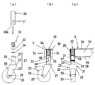
(1) 運搬用台車50は、床フレーム1の進行方向55の前側および後ろ側の端に側面パネル12、12を着脱自在に取り付け、床フレーム1の四隅に自在キャスター20、20、進行方向55の中間位置に固定キャスター40、40を取り付けて、床フレーム1上に起伏可能にパレット10を乗せて、構成する(図5)。
床フレーム1は、進行方向55に沿ってメインフレーム2を配置し、メインフレーム2の両端部4、4の下面に、メインフレーム2に直交する端部フレーム片5、5をそれぞれ固定し、メインフレーム2の中間部の下面に、メインフレーム2に直交する中間フレーム片7の中間部を固定して、構成する(図5(a)(b))。
(1) The
The
(2) 自在キャスター40は、天板23の下面に所定間隔を空けて支持片22、22を配置してなるキャスターフレーム21に、車輪25の軸26を支持片22、22に軸止めして、天板23の上面に取付軸27を固定して構成する。取付軸27には、略水平方向のピン孔28を形成してある。
また、端部フレーム片5、5で、両側の自在キャスター20の取付位置に併せて、ガイドパイプ30、30を、軸を略垂直に配置して、固定する。ガイドパイプ30の下部には、鉛直方向の長孔31(ピン孔28に対応)を形成してあり、ガイドパイプ30の上端は、端部フレーム片5により塞さがれている。
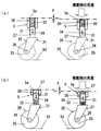
ガイドパイプ30内にスプリングばね32を、軸を合わせて(垂直にして)挿入して、続いて、ワッシャー33を介して、自在キャスター20の取付軸27をガイドパイプ30内に挿入する。続いて、ガイドパイプ30の長孔31から、略水平方向にピン34を挿入して、取付軸27のピン孔28を貫通して、ピン34は他側の長孔31を貫通する。スプリングばね32に加圧をしない状態(または加圧が少ない状態)で、ピン34は長孔31の下端に位置し、加圧にしたがって、ピン34は長孔31の上方に移動できるように、ピン34、ピン孔28および長孔31は調整されている。
また、端部フレーム片5は、パイプ材や溝形材で、断面長方形状(または正方形状)に形成され、
上面5a、下面5bおよび側面5c、5cを有する。ガイドパイプ30を、端部フレーム片5の下面側の板を貫通して(あるいは、下面側の隙間に挿入されて)、ガイドパイプ30の上端を上面板の下面に固定する(図1(a)(b)(c)、図3(a))。
(2) The
In addition, the
The
Further, the
It has an
(3) 中間フレーム片7の下面の両側に、それぞれ固定キャスター40、40を取り付ける。固定キャスター40はキャスターフレーム41に車輪42を軸止めして構成する(図4(a)(b))。進行方向55に直交する方向で、固定キャスター40の車輪42、42は、自在キャスター20の車輪25、25の外端よりも内側に位置している(図4(c))。
従来例(図6)の場合では、平面視で自在キャスター20の外側および内側に、スプリングばねを配置する必要があった。この実施形態のように、床フレームの1の外周に近い側に自在キャスター20、20を配置する場合には、自在キャスター20の取付軸27にスプリングばね32を設けた構造が適している。
(3) The fixed
In the case of the conventional example (FIG. 6), it is necessary to arrange spring springs on the outer side and the inner side of the
(4) パレット10に荷物(積載物)を載せない様態で、すなわち、6つのキャスター20、40に運搬用台車50の自重のみが作用する段階で、四隅の自在キャスター20、20の車輪25、25のみが接地して、固定キャスター40の車輪42は、接地せずに、地面53からPcm程度浮いた状態となっている(図4(b))。
また、パレットに荷物を、例えば50kg程度(作用積載量)乗せた状態で、各スプリングばね32、32はPだけ縮み(図3(a))、固定キャスター40、40の車輪42、4が接地するように、スプリングばね32は、そのばね定数が設定されている。
(4) In a state where no load (loading material) is placed on the
Further, with the load placed on the pallet, for example, about 50 kg (work load), the spring springs 32 and 32 are contracted by P (FIG. 3A), and the
(5) この運搬用台車50では、自在キャスター20の構成において、通常の自在キャスターでもガイドパイプ30に自在キャスター20の取付軸27を挿入して構成するので、ピン孔28や長孔31の加工のみで、運搬用台車50を構成できる。また、スプリングばね32の軸方向の長さ分(鉛直方向の長さ)だけ、高さが高くなるだけであるので、従来の運搬用台車に較べて、パレット10の高さ位置に大きな変化は無い。
(5) In this transporting
2.運搬用台車50の使用
2. Use of
(1) パレット10に何も乗せない状態で、スプリングばね32により、進行方向55の前後両側の自在キャスター20、20の車輪25、25のみが接地して、固定キャスター40の車輪43は、地面53からPcm程度上がった状態にあり、接地しない(図4(b)(c))。この状態で、ピン34は長孔31の下端部に位置し、自在キャスター20は、床フレーム1に対して、最も下がった位置にある(図3(a)左側)。この状態で、固定キャスター40の車輪42が接地せず、四隅の自在キャスター20、20の車輪25、25のみが接地して、進行方向55に直角な方向への移動など、自由な引き回しが可能となっている。
したがって、この状態で、パレット10を側面パネル12に沿うように起こせば、複数台の運搬用台車50、50を重ねて、ネスティングが可能である。この際、一方の運搬用台車50の床フレーム1のメインフレーム2の下方を、他の運搬用台車50の端部フレーム片5、5、中間フレーム片7が通過できるので、平面視で、メインフレーム片2、2を沿わせた状態でネスティングができる(図示していない)。
(1) With nothing placed on the
Therefore, if the
(2) 続いて、パレット10が伏せた状態で(パレット10が床フレーム1上にある状態、水平位置)で、通常の運搬用台車50と同様に、パレット10に荷物を載せて運搬ができる。
(2) Subsequently, in the state where the
この際、荷物の重量が、上記作用積載量を超えた場合、スプリングばね32、32が縮み、床フレーム1が高さ方向でP程度下り(図3)、固定キャスター40の車輪42が接地する(図5(b)(c))。この状態で、固定キャスター40の車輪43と、四隅の自在キャスター20、20の合計4つの車輪25、25とが、すべて地面53に接地するが、固定キャスター40の車輪42が接地しているので、運搬用台車50を進行方向55へ、直進性を高めて安定して走行させることができる。
また、従来の中間部の固定キャスターを昇降させるタイプ(特許文献1、2)では、固定キャスターの車輪と前後いずれか一方の自在キャスターの車輪とが接地するので(すなわち接地していない側の自在キャスターの車輪は浮いている)、パレットがやや傾斜し、また固定キャスターの車輪を支点にシーソーのように若干動くことになっていた。しかし、この運搬用台車50では、固定キャスター40の車輪42と前後両側の自在キャスター20、20の車輪25、25との両方が接地するので、より安定して走行できる(図5(b)(c))。また、地面53に凹凸が合った場合でも、自在キャスター20の車輪25、25が独立して昇降するので、凹凸の衝撃を吸収できる。さらに、自在キャスター20の車輪25は取付軸27を軸として、略鉛直方向に昇降するので、作動に無駄が無く、自在キャスター20の取付軸周りの回動の障害もなく、スムースな走行ができる。
At this time, if the weight of the load exceeds the working load, the spring springs 32 and 32 are contracted, the
Further, in the conventional type (
3.他の実施態様 3. Other embodiments
(1) 前記実施態様において、固定キャスターは2つ設けたが、少なくとも1つあれば良く、他の構成とすることもできる(図示していない)。 (1) In the above-described embodiment, two fixed casters are provided. However, at least one fixed caster is sufficient, and other configurations may be used (not shown).
(2) また、前記実施態様において、作用積載量は、50kgとしたが、台車の積載量により30kg〜150kg程度で調整する。 (2) Moreover, in the said embodiment, although the action load amount was 50 kg, it adjusts with about 30 kg-150 kg with the load amount of a trolley | bogie.
4.第2の実施態様の自在キャスター 4). Swivel caster of the second embodiment
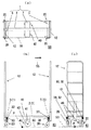
(1) 前記実施態様の自在キャスター20では、自在キャスター20の取付軸27を挿入するガイドパイプ30内にスプリングばね32を挿入して、ガイドパイプ30の上面(端部フレーム5の下面)と取付軸の上端と、の間でスプリングばねを作用させたが、他の構成とすることもできる。したがって、第1の実施態様では、
取付軸27の外径<スプリングばね32の内径
<スプリングばね32の外径<ガイドパイプ30の内径
となっている(図1(a))。すなわち、端部フレーム5と取付軸27の上端との間で、スプリングばね32を作用させる構造である。
(1) In the
Outer diameter of mounting
<Outer diameter of
(2) 第2の実施態様では、例えば、
取付軸27の外径<ガイドパイプ30の内径≒スプリングばね32の内径
とすることもできる(図2(a))。
すなわち、ガイドパイプ30の下縁30aと自在キャスター20のキャスターフレーム21の天板23の上面との間にスプリングばねの上下を配置した状態で、ガイドパイプ30内に自在キャスター20の取付軸27を挿入してある。そして、第1の実施態様と同様に、ガイドパイプ30の長孔31と取付軸27のピン孔28との間にピン34を挿入して、自在キャスター20を構成する(図2(a)(b)(c))。
したがって、第2の実施態様では、スプリングばね32は、ガイドパイプ30の下縁30a(ガイドパイプ30を介して端部フレーム5に作用する)と、自在キャスター20のキャスターフレーム21の天板23の上面との間で、作用することになる。
また、この実施態様のスプリングばね32も、同様に、パレット10に荷物を50kg程度(作用積載量)乗せた状態で、スプリングばね32はPだけ縮み(図2(b))、固定キャスター40の車輪が接地するように(図4、図5参照)、スプリングばね32は、そのばね定数が設定されている。
(2) In the second embodiment, for example,
The outer diameter of the mounting
That is, the mounting
Accordingly, in the second embodiment, the
Similarly, the
(3)他の構成は、前記実施態様と同様である(図示していない。図4、図5参照)。 (3) Other configurations are the same as those in the above-described embodiment (not shown, see FIGS. 4 and 5).
1 床フレーム
2 メインフレーム(床フレーム)
5 端部フレーム(床フレーム)
5a 端部フレームの上面
5b 端部フレームの下面
5c 端部フレームの側面
7 中間フレーム(床フレーム)
10 パレット
12 側面パネル
20 自在キャスター
21 キャスターフレーム(自在キャスター)
22 支持片(キャスターフレーム)
23 天板(キャスターフレーム)
25 車輪(自在キャスター)
26 軸(自在キャスター)
27 取付軸(自在キャスター)
28 ピン孔(自在キャスター)
30 ガイドパイプ
30a ガイドパイプの下縁
31 長孔(ガイドパイプ)
32 スプリングばね
33 ワッシャー
34 ピン
40 固定キャスター
41 キャスターフレーム(固定キャスター)
42 車輪(固定キャスター)
50 運搬用台車
53 地面
55 進行方向
60 運搬用台車(従来例)
61 自在キャスター(従来例)
62 床フレーム(従来例)
63 水平板(従来例)
64 保持筒(従来例)
65、66 スプリングばね(従来例)
1
5 End frame (floor frame)
5a End frame
10
22 Support piece (caster frame)
23 Top plate (caster frame)
25 wheels (free casters)
26 shafts (free casters)
27 Mounting shaft (free caster)
28 pin holes (free casters)
30
32
42 wheels (fixed casters)
50
61 Swivel caster (conventional example)
62 Floor frame (conventional example)
63 Horizontal plate (conventional example)
64 Holding cylinder (conventional example)
65, 66 Spring spring (conventional example)
Claims (2)
(1) 前記床フレームの下面で、前記運搬用台車の進行方向、前側及び後ろ側に自在キャスターを設け、かつ進行方向で、中間部に固定キャスターを設けた。
(2) 前記全ての自在キャスターは、キャスターフレームに車輪を軸止めし、前記キャスターフレームの上部の取付軸を前記床フレームに対して、略直角でかつ回転自在に取り付けた。
(3) 前記取付軸は、前記床フレームに対して軸方向に昇降自在として、かつ前記取付軸と同軸にスプリングばねを設けた。
(4)前記スプリングばねは、
「前記パレットに荷物を載せない様態で、
前記自在車輪のみが接地し、前記固定キャスターの固定車輪が接地しない」ように構成し、
かつ
「前記パレットに荷物を載せた状態で、前記前後の自在車輪と前記固定車輪との両方が接地する」ように構成した。 A transport cart characterized in that a floor frame is provided below a pallet on which a load is placed and a caster is provided on the lower surface of the floor frame, and is configured as follows.
(1) On the lower surface of the floor frame, free casters were provided in the traveling direction, front side and rear side of the transporting carriage, and fixed casters were provided in the middle in the traveling direction.
(2) All the free casters have their wheels fixed to the caster frame, and the upper mounting shaft of the caster frame is attached to the floor frame at a substantially right angle and freely rotatable.
(3) The mounting shaft is movable up and down in the axial direction with respect to the floor frame, and a spring spring is provided coaxially with the mounting shaft.
(4) The spring spring is
“With no load on the pallet,
Only the universal wheels are grounded, and the fixed wheels of the fixed casters are not grounded.
In addition, “both the front and rear universal wheels and the fixed wheels are in contact with each other with a load placed on the pallet”.
(1) 床フレームの四隅に、軸を縦にしてガイドパイプをそれぞれ固定し、前記ガイドパイプに自在キャスターの取付軸を回転自在でかつ昇降自在に挿入した。
(2) スプリングばねを
「前記ガイドパイプ内で、前記床フレームの下方で前記取付軸の上縁との間」
または「取付軸の外周で、キャスターフレームの上方で前記ガイドパイプの下縁との間」に取り付けた。 The carriage according to claim 1, configured as follows.
(1) The guide pipes were fixed to the four corners of the floor frame with the shafts vertically, and the mounting shafts of the free casters were inserted into the guide pipes so as to be rotatable and movable up and down.
(2) The spring spring is “between the upper edge of the mounting shaft in the guide pipe and below the floor frame”
Alternatively, it is attached “between the lower edge of the guide pipe and the outer periphery of the attachment shaft, above the caster frame”.
Priority Applications (1)
| Application Number | Priority Date | Filing Date | Title |
|---|---|---|---|
| JP2015213505A JP6730018B2 (en) | 2015-10-29 | 2015-10-29 | Trolley for transportation |
Applications Claiming Priority (1)
| Application Number | Priority Date | Filing Date | Title |
|---|---|---|---|
| JP2015213505A JP6730018B2 (en) | 2015-10-29 | 2015-10-29 | Trolley for transportation |
Publications (2)
| Publication Number | Publication Date |
|---|---|
| JP2017081472A true JP2017081472A (en) | 2017-05-18 |
| JP6730018B2 JP6730018B2 (en) | 2020-07-29 |
Family
ID=58711549
Family Applications (1)
| Application Number | Title | Priority Date | Filing Date |
|---|---|---|---|
| JP2015213505A Active JP6730018B2 (en) | 2015-10-29 | 2015-10-29 | Trolley for transportation |
Country Status (1)
| Country | Link |
|---|---|
| JP (1) | JP6730018B2 (en) |
Cited By (3)
| Publication number | Priority date | Publication date | Assignee | Title |
|---|---|---|---|---|
| CN107697118A (en) * | 2017-08-22 | 2018-02-16 | 安徽明瑞智能科技股份有限公司 | One kind is used for charging pile conveying arrangement |
| KR20220006308A (en) * | 2020-07-08 | 2022-01-17 | 주식회사 그린플러스 | removable caster for pallet |
| CN114259925A (en) * | 2021-12-23 | 2022-04-01 | 湖南新中意食品有限公司 | High-speed mixer is used in preparation of nougat bubble base |
-
2015
- 2015-10-29 JP JP2015213505A patent/JP6730018B2/en active Active
Cited By (4)
| Publication number | Priority date | Publication date | Assignee | Title |
|---|---|---|---|---|
| CN107697118A (en) * | 2017-08-22 | 2018-02-16 | 安徽明瑞智能科技股份有限公司 | One kind is used for charging pile conveying arrangement |
| KR20220006308A (en) * | 2020-07-08 | 2022-01-17 | 주식회사 그린플러스 | removable caster for pallet |
| KR102386202B1 (en) | 2020-07-08 | 2022-04-13 | 주식회사 그린플러스 | Pallet caster's detachable structure |
| CN114259925A (en) * | 2021-12-23 | 2022-04-01 | 湖南新中意食品有限公司 | High-speed mixer is used in preparation of nougat bubble base |
Also Published As
| Publication number | Publication date |
|---|---|
| JP6730018B2 (en) | 2020-07-29 |
Similar Documents
| Publication | Publication Date | Title |
|---|---|---|
| KR20190015302A (en) | Self-propelled module for overloading | |
| JP2017081472A (en) | Carriage for transportation | |
| US20160362033A1 (en) | Floor-bound transport vehicle for containers, featuring a lifting function | |
| JP2009227042A (en) | Transportation carriage | |
| KR101857102B1 (en) | Crane | |
| CN105253818A (en) | Fork mechanism of forklift | |
| JP2018048004A (en) | Article conveying vehicle | |
| CN105460643A (en) | Logistics unloading device | |
| AU2017318205A1 (en) | Industrial truck and drive wheel bearing device for industrial trucks | |
| CN204529249U (en) | A kind of low clearance Omni-mobile lifting platform truck | |
| CN103072923A (en) | Hand fork lifter capable of being conveniently steered | |
| JP6585466B2 (en) | Carriage truck with side panels | |
| SE1551067A1 (en) | Roll container | |
| KR20130052244A (en) | Fitting-removing apparetus of the vehicle and loading box | |
| CN212387598U (en) | Straddle carrier | |
| JP5616660B2 (en) | Installation method of cart and heavy load | |
| JP2006103516A (en) | Hand-pushed truck | |
| KR20100065820A (en) | Heavy weight moving apparatus | |
| JP2008149758A5 (en) | ||
| CN207918278U (en) | Crane travelling gear carrying tooling | |
| KR20220168432A (en) | Carrier wagon with lift table | |
| JP6587876B2 (en) | Handling equipment | |
| JP2002002492A (en) | Carrying truck | |
| CN108100867A (en) | Crane travelling gear carrying tooling | |
| KR102623226B1 (en) | Caterpillar type foldable forklift with center of gravity movement |
Legal Events
| Date | Code | Title | Description |
|---|---|---|---|
| A621 | Written request for application examination |
Free format text: JAPANESE INTERMEDIATE CODE: A621 Effective date: 20181017 |
|
| A977 | Report on retrieval |
Free format text: JAPANESE INTERMEDIATE CODE: A971007 Effective date: 20190711 |
|
| A131 | Notification of reasons for refusal |
Free format text: JAPANESE INTERMEDIATE CODE: A131 Effective date: 20190716 |
|
| A521 | Request for written amendment filed |
Free format text: JAPANESE INTERMEDIATE CODE: A523 Effective date: 20190917 |
|
| A131 | Notification of reasons for refusal |
Free format text: JAPANESE INTERMEDIATE CODE: A131 Effective date: 20200107 |
|
| A521 | Request for written amendment filed |
Free format text: JAPANESE INTERMEDIATE CODE: A523 Effective date: 20200305 |
|
| TRDD | Decision of grant or rejection written | ||
| A01 | Written decision to grant a patent or to grant a registration (utility model) |
Free format text: JAPANESE INTERMEDIATE CODE: A01 Effective date: 20200519 |
|
| A61 | First payment of annual fees (during grant procedure) |
Free format text: JAPANESE INTERMEDIATE CODE: A61 Effective date: 20200702 |
|
| R150 | Certificate of patent or registration of utility model |
Ref document number: 6730018 Country of ref document: JP Free format text: JAPANESE INTERMEDIATE CODE: R150 |
|
| R250 | Receipt of annual fees |
Free format text: JAPANESE INTERMEDIATE CODE: R250 |