JP2017041602A - On-vehicle electronic apparatus - Google Patents

On-vehicle electronic apparatus Download PDF

Info

Publication number
JP2017041602A
JP2017041602A JP2015163926A JP2015163926A JP2017041602A JP 2017041602 A JP2017041602 A JP 2017041602A JP 2015163926 A JP2015163926 A JP 2015163926A JP 2015163926 A JP2015163926 A JP 2015163926A JP 2017041602 A JP2017041602 A JP 2017041602A
Authority
JP
Japan
Prior art keywords
wall portion
circuit board
side wall
damping member
vehicle
Prior art date
Legal status (The legal status is an assumption and is not a legal conclusion. Google has not performed a legal analysis and makes no representation as to the accuracy of the status listed.)
Granted
Application number
JP2015163926A
Other languages
Japanese (ja)
Other versions
JP6451554B2 (en
Inventor
真義 山田
Masayoshi Yamada
真義 山田
Current Assignee (The listed assignees may be inaccurate. Google has not performed a legal analysis and makes no representation or warranty as to the accuracy of the list.)
Denso Corp
Original Assignee
Denso Corp
Priority date (The priority date is an assumption and is not a legal conclusion. Google has not performed a legal analysis and makes no representation as to the accuracy of the date listed.)
Filing date
Publication date
Application filed by Denso Corp filed Critical Denso Corp
Priority to JP2015163926A priority Critical patent/JP6451554B2/en
Publication of JP2017041602A publication Critical patent/JP2017041602A/en
Application granted granted Critical
Publication of JP6451554B2 publication Critical patent/JP6451554B2/en
Active legal-status Critical Current
Anticipated expiration legal-status Critical

Links

Images

Landscapes

  • Mounting Of Printed Circuit Boards And The Like (AREA)

Abstract

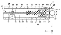
PROBLEM TO BE SOLVED: To suppress a vibration of a circuit board with a vehicle vibration concerning an on-vehicle electronic apparatus to be attached to a vehicle by an attachment part arranged on side wall parts.SOLUTION: An on-vehicle electronic apparatus includes: a circuit board 12 mounting an electronic component 22; a housing 14 having an upper wall part 30, a lower wall part 32, and a side wall part 34 as the wall parts for regulating an internal space 26 so as to store a circuit board in the internal space; and an attachment part 16 arranged outside the internal space in order to perform attachment to a vehicle and continuing to the side wall part. The circuit board is supported by a pedestal part 44 arranged on an inner surface 32a of the lower wall part and a heat conduction member 48 arranged on the pedestal part 44. The side wall part to which the attachment part continues has projections 46 projected from an inner surface 34a of the self wall part. Vibration control members 18 are fitted to the projections. The circuit board is fixed to the housing via the vibration control members.SELECTED DRAWING: Figure 2

Description

本発明は、回路基板と、壁部により規定される内部空間に回路基板を収容する筐体と、上壁部の内面及び下壁部の内面の少なくとも一方に設けられ、回路基板を支持する支持部と、を備え、側壁部に連なる取り付け部により、車両に取り付けられる車載電子装置に関するものである。   The present invention provides a circuit board, a housing that accommodates the circuit board in an internal space defined by the wall, and a support that supports the circuit board and is provided on at least one of the inner surface of the upper wall and the inner surface of the lower wall. And an in-vehicle electronic device that is attached to the vehicle by an attachment portion that is continuous with the side wall portion.

回路基板と、壁部により規定される内部空間に回路基板を収容する筐体と、上壁部の内面及び下壁部の内面の少なくとも一方に設けられ、回路基板を支持する支持部と、を備える車載電子装置が、特許文献1に開示されている。   A circuit board, a housing that accommodates the circuit board in an internal space defined by the wall, and a support that is provided on at least one of the inner surface of the upper wall and the inner surface of the lower wall and supports the circuit board. An in-vehicle electronic device provided is disclosed in Patent Document 1.

この車載電子装置において、筐体は、一面が開口する箱状の筐体本体と、筐体本体の開口を閉塞する蓋体とにより構成されている。筐体は、壁部として、回路基板の一面に対向する上壁部(蓋体)と、一面と反対の裏面に対向する下壁部(筐体本体)と、上壁部と側壁部を連結する側壁部(筐体本体)と、を有している。下壁部の内面には、回路基板を支持する支持部(ボス)が設けられている。回路基板は、ねじによって支持部に固定されている。また、側壁部には段差が設けられ、回路基板の周辺部分が段差に載置されている。   In this in-vehicle electronic device, the casing is configured by a box-shaped casing main body that opens on one surface and a lid that closes the opening of the main casing. The housing is connected to the upper wall portion (lid) facing one surface of the circuit board, the lower wall portion (housing body) facing the back surface opposite to the one surface, and the upper wall portion and the side wall portion as the wall portion. And a side wall portion (housing body). A support portion (boss) for supporting the circuit board is provided on the inner surface of the lower wall portion. The circuit board is fixed to the support portion with screws. Further, the side wall is provided with a step, and the peripheral portion of the circuit board is placed on the step.

特開平11−284374号公報JP-A-11-284374

上記した車載電子装置は、たとえば側壁部に連なる取り付け部により、車両に取り付けられる。この取り付け構造の場合、車両振動は、取り付け部を介して側壁部に伝播する。上記したように、回路基板の周辺部分は段差に載置されているため、車両振動は、主として下壁部(及び上壁部)に伝播し、支持部を通じて回路基板に入力される。車両振動の入力により、回路基板は、支持部による支持位置を節として上下に撓むように振動する。回路基板の周辺部分は段差に載置されており、固定されていないため、振動を抑制できるのは、支持部による支持位置周辺のみである。   The above-described on-vehicle electronic device is attached to the vehicle, for example, by an attachment portion connected to the side wall portion. In the case of this mounting structure, vehicle vibration propagates to the side wall portion via the mounting portion. As described above, since the peripheral portion of the circuit board is placed on the step, the vehicle vibration propagates mainly to the lower wall (and the upper wall) and is input to the circuit board through the support. By the input of the vehicle vibration, the circuit board vibrates so as to bend up and down with the support position by the support portion as a node. Since the peripheral portion of the circuit board is mounted on the step and is not fixed, vibration can be suppressed only in the vicinity of the support position by the support portion.

また、段差によって下方向への振動を抑制することができる。しかしながら、段差部によって上方向への振動を抑制することはできない。仮に回路基板の周辺部分を段差に固定したとしても、段差による支持位置が節となり、支持部による支持位置と段差による支持位置との間の部分が腹となって振動する。   Further, downward vibration can be suppressed by the step. However, the upward vibration cannot be suppressed by the stepped portion. Even if the peripheral portion of the circuit board is fixed to the step, the support position by the step becomes a node, and the portion between the support position by the support portion and the support position by the step becomes an antinode and vibrates.

本発明は上記問題点に鑑み、側壁部に連なる取り付け部により、車両に取り付けられる車載電子装置において、車両振動にともなう回路基板の振動を抑制することを目的とする。   In view of the above problems, an object of the present invention is to suppress vibration of a circuit board caused by vehicle vibration in an in-vehicle electronic device attached to a vehicle by an attachment portion connected to the side wall portion.

ここに開示される発明は、上記目的を達成するために以下の技術的手段を採用する。なお、特許請求の範囲及びこの項に記載した括弧内の符号は、ひとつの態様として後述する実施形態に記載の具体的手段との対応関係を示すものであって、発明の技術的範囲を限定するものではない。   The invention disclosed herein employs the following technical means to achieve the above object. Note that the reference numerals in parentheses described in the claims and in this section indicate a corresponding relationship with specific means described in the embodiments described later as one aspect, and limit the technical scope of the invention. Not what you want.

開示された発明のひとつは、一面(20a)と、一面と厚さ方向において反対の裏面(20b)と、を有し、一面及び裏面の少なくとも一方に電子部品(22)が実装された回路基板(12)と、
内部空間(26)を規定する壁部(28)として、一面側に配置された上壁部(30)と、裏面側に配置された下壁部(32)と、上壁部と下壁部とを連結する側壁部(34)と、を有し、内部空間に回路基板を収容する筐体(14)と、
上壁部の内面(30a)及び下壁部の内面(32a)の少なくとも一方に設けられ、回路基板を支持する支持部(44,48)と、
内部空間の外部に設けられ、側壁部に連なる取り付け部(16)と、
を備え、
取り付け部により、車両に取り付けられる車載電子装置であって、
取り付け部が連なる側壁部は、自身の内面(34a)から突出する凸部(46)を有し、
筐体を構成する材料よりも損失係数が大きい材料を用いて形成され、凸部に対応する第1凹部(54)を有し、第1凹部と凸部との嵌合により筐体に固定された制振部材(18)をさらに備え、
回路基板は、制振部材を介して筐体に固定されていることを特徴とする。
One of the disclosed inventions has a circuit board having one surface (20a) and a back surface (20b) opposite to the one surface in the thickness direction, and an electronic component (22) mounted on at least one of the one surface and the back surface. (12)
As wall part (28) which prescribes | regulates internal space (26), the upper wall part (30) arrange | positioned at one surface side, the lower wall part (32) arrange | positioned at the back surface side, an upper wall part, and a lower wall part A side wall (34) for connecting the circuit board and housing a circuit board in the internal space,
A support portion (44, 48) provided on at least one of the inner surface (30a) of the upper wall portion and the inner surface (32a) of the lower wall portion and supporting the circuit board;
A mounting portion (16) provided outside the internal space and connected to the side wall portion;
With
An in-vehicle electronic device attached to a vehicle by an attachment part,
The side wall part where the attachment part continues has a convex part (46) protruding from its inner surface (34a),
It is formed using a material having a loss factor larger than that of the material constituting the housing, has a first recess (54) corresponding to the convex portion, and is fixed to the housing by fitting the first concave portion and the convex portion. A vibration damping member (18),
The circuit board is fixed to the housing via a vibration damping member.

本発明では、側壁部が内面から突出する凸部を有しているため、取り付け部から側壁部へ伝わる車両振動が凸部を介して制振部材に伝播しやすい。また、振動は、剛性の高いほうに伝播しやすいが、側壁部において凸部を設けた部分の剛性が他の部分よりも高まっているため、車両振動が凸部を介して制振部材に伝播しやすい。このように凸部を設けることで、車両振動を側壁部から制振部材に効果的に入力させることができる。制振部材は筐体よりも損失係数が大きいため、車両振動を、厚さ方向において凸部両側に位置する制振部材により、効果的に減衰させることができる。   In this invention, since the side wall part has the convex part which protrudes from an inner surface, the vehicle vibration transmitted to a side wall part from an attaching part tends to propagate to a damping member via a convex part. In addition, vibration tends to propagate to the higher rigidity, but because the rigidity of the part where the convex part is provided in the side wall part is higher than the other part, the vehicle vibration propagates to the damping member via the convex part. It's easy to do. By providing the convex portion in this way, vehicle vibration can be effectively input from the side wall portion to the vibration damping member. Since the damping member has a larger loss coefficient than the casing, the vehicle vibration can be effectively damped by the damping members located on both sides of the convex portion in the thickness direction.

また、車両振動を側壁部から制振部材に効果的に入力させることができるため、上壁部や下壁部に伝播される車両振動を従来に較べて低減することができる。これにより、車両振動が、支持部を通じて回路基板に入力されるのを抑制することができる。   Further, since vehicle vibration can be effectively input from the side wall portion to the damping member, vehicle vibration propagated to the upper wall portion and the lower wall portion can be reduced as compared with the conventional case. Thereby, it can suppress that a vehicle vibration is input into a circuit board through a support part.

以上により、本発明によれば、側壁部に設けられた取り付け部により、車両に取り付けられる車載電子装置において、車両振動にともなう回路基板の振動を抑制することができる。   As described above, according to the present invention, in the in-vehicle electronic device attached to the vehicle, the vibration of the circuit board due to the vehicle vibration can be suppressed by the attaching portion provided on the side wall portion.

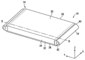
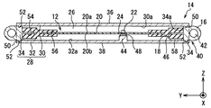
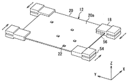
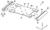
第1実施形態に係る車載電子装置の概略構成を示す斜視図である。It is a perspective view showing a schematic structure of an in-vehicle electronic device concerning a 1st embodiment. 図1のII-II線に沿う断面図である。It is sectional drawing which follows the II-II line of FIG. 上ケースを外した状態を示す斜視図である。It is a perspective view which shows the state which removed the upper case. 上ケースを示す斜視図である。It is a perspective view which shows an upper case. 車載電子装置の組み付け方法を示す図である。It is a figure which shows the assembly method of a vehicle-mounted electronic device. 車載電子装置の組み付け方法を示す図である。It is a figure which shows the assembly method of a vehicle-mounted electronic device. 車載電子装置の組み付け方法を示す図である。It is a figure which shows the assembly method of a vehicle-mounted electronic device. 制振部材周辺を拡大した図である。It is the figure which expanded the damping member periphery. 第2実施形態に係る車載電子装置において、制振部材周辺を拡大した図であり、図8に対応している。In the on-vehicle electronic device according to the second embodiment, it is an enlarged view of the periphery of the damping member, and corresponds to FIG. その他変形例を示す図であり、図8に対応している。It is a figure which shows another modification, and respond | corresponds to FIG.

以下、本発明の実施形態を、図面を参照して説明する。なお、以下に示す各図において、共通乃至関連する要素には同一の符号を付与するものとする。また、回路基板の厚さ方向をZ方向、Z方向に直交する一方向をX方向と示す。まら、Z方向及びX方向の両方向に直交する方向をY方向と示す。特に断りのない限り、XY面に沿う形状を平面形状とする。   Embodiments of the present invention will be described below with reference to the drawings. In the drawings shown below, common or related elements are given the same reference numerals. Further, the thickness direction of the circuit board is indicated as the Z direction, and one direction orthogonal to the Z direction is indicated as the X direction. In addition, a direction orthogonal to both the Z direction and the X direction is referred to as a Y direction. Unless otherwise specified, the shape along the XY plane is a planar shape.

(第1実施形態)
先ず、図1〜図4に基づき、本実施形態に係る車載電子装置10について説明する。
(First embodiment)
First, the in-vehicle electronic device 10 according to the present embodiment will be described with reference to FIGS.

図1〜図4に示すように、車載電子装置10は、回路基板12と、回路基板12を収容する筐体14と、車両への取り付け部16と、制振部材18と、を備えている。車載電子装置10は、たとえば車両に搭載されたエンジンを制御する防水構造のエンジンECU(Electric Control Unit)として構成されている。   As shown in FIGS. 1 to 4, the in-vehicle electronic device 10 includes a circuit board 12, a casing 14 that houses the circuit board 12, a vehicle mounting portion 16, and a damping member 18. . The in-vehicle electronic device 10 is configured as a waterproof engine ECU (Electric Control Unit) that controls an engine mounted on a vehicle, for example.

図2及び図3に示すように、回路基板12は、樹脂などの電気絶縁性基材に配線が配置されてなる配線基板20と、配線基板20に実装された電子部品22と、を有している。配線基板20は、プリント基板とも称される。配線基板20は平面略矩形状をなしており、矩形を規定する隣り合う2辺の一方がX方向に略平行とされ、他方がY方向に略平行とされている。詳しくは、図3に示すように、Y方向が配線基板20の長手方向、X方向が短手方向となっている。   As shown in FIGS. 2 and 3, the circuit board 12 includes a wiring board 20 in which wiring is arranged on an electrically insulating base material such as a resin, and an electronic component 22 mounted on the wiring board 20. ing. The wiring board 20 is also referred to as a printed board. The wiring board 20 has a substantially rectangular plane shape, and one of two adjacent sides defining the rectangle is substantially parallel to the X direction, and the other is substantially parallel to the Y direction. Specifically, as shown in FIG. 3, the Y direction is the longitudinal direction of the wiring board 20, and the X direction is the short direction.

電子部品22は、配線基板20におけるZ方向の一面20a及び一面20aと反対の裏面20bのうち、少なくとも一方に実装されている。本実施形態では、一例として、配線基板20の一面20aに電子部品22が実装されている。一面20aは、回路基板12の一面でもあり、裏面20bは回路基板12の裏面でもある。   The electronic component 22 is mounted on at least one of the one surface 20a in the Z direction on the wiring board 20 and the back surface 20b opposite to the one surface 20a. In the present embodiment, as an example, the electronic component 22 is mounted on the one surface 20a of the wiring board 20. The one surface 20 a is also one surface of the circuit board 12, and the back surface 20 b is also the back surface of the circuit board 12.

電子部品22としては、MOSFETなどのスイッチング素子、ダイオード、コンデンサ、抵抗、マイコンなどを採用することができる。図2に示すように、配線基板20には、電子部品22のうち、発熱量の大きい部品に対応してサーマルビア24が形成されている。   As the electronic component 22, a switching element such as a MOSFET, a diode, a capacitor, a resistor, a microcomputer, or the like can be employed. As shown in FIG. 2, thermal vias 24 are formed on the wiring board 20 so as to correspond to components that generate a large amount of heat among the electronic components 22.

筐体14は、回路基板12を収容する内部空間26を規定する壁部28を有している。壁部28は、一面20a側に配置される上壁部30と、裏面20b側に配置される下壁部32と、上壁部30と下壁部32とを連結する側壁部34と、を含んでいる。上壁部30及び下壁部32は、Z方向からの投影視において、回路基板12を内包している。側壁部34は、Z方向からの投影視において、回路基板12を取り囲んでいる。図2及び図3では、側壁部34と取り付け部16との境界を破線で示している。筐体14は、樹脂や金属を用いて形成されている。   The housing 14 has a wall portion 28 that defines an internal space 26 that accommodates the circuit board 12. The wall portion 28 includes an upper wall portion 30 disposed on the one surface 20a side, a lower wall portion 32 disposed on the back surface 20b side, and a side wall portion 34 connecting the upper wall portion 30 and the lower wall portion 32. Contains. The upper wall portion 30 and the lower wall portion 32 include the circuit board 12 in a projection view from the Z direction. The side wall portion 34 surrounds the circuit board 12 when viewed from the Z direction. 2 and 3, the boundary between the side wall portion 34 and the attachment portion 16 is indicated by a broken line. The housing 14 is formed using resin or metal.

本実施形態では、筐体14全体が、金属(たとえばアルミニウム)を用いて形成されている。図1〜図4に示すように、筐体14は、主として回路基板12の一面20a側に配置される上ケース36と、主として裏面20b側に配置される下ケース38と、Z方向に直交する一方向において、回路基板12を間に挟むように配置される一対の横ケース40と、を有している。そして、上ケース36、下ケース38、及び一対の横ケース40を、嵌合やねじ締結によって組み付けることで、筐体14が構成されている。   In the present embodiment, the entire housing 14 is formed using metal (for example, aluminum). As shown in FIGS. 1 to 4, the housing 14 is orthogonal to the Z direction, with an upper case 36 disposed mainly on the one surface 20 a side of the circuit board 12 and a lower case 38 disposed mainly on the back surface 20 b side. It has a pair of horizontal cases 40 arranged so as to sandwich the circuit board 12 in one direction. And the housing | casing 14 is comprised by attaching the upper case 36, the lower case 38, and a pair of side case 40 by fitting or screw fastening.

筐体14は、平面略矩形状の配線基板20に対応して4つの側壁部34を有している。上ケース36は、上壁部30とともに、2つの側壁部を構成している。下ケース38は、下壁部32を構成している。横ケース40は、側壁部34の残りを構成している。詳しくは、横ケース40が、回路基板12に対してY方向の両側に配置されている。このように、一対の横ケース40の間に回路基板12が配置されている。一対の横ケース40は、2つの側壁部34を構成している。   The housing 14 has four side wall portions 34 corresponding to the wiring substrate 20 having a substantially planar shape. The upper case 36 constitutes two side wall portions together with the upper wall portion 30. The lower case 38 constitutes the lower wall portion 32. The lateral case 40 constitutes the remainder of the side wall portion 34. Specifically, the lateral case 40 is disposed on both sides in the Y direction with respect to the circuit board 12. Thus, the circuit board 12 is disposed between the pair of horizontal cases 40. The pair of lateral cases 40 constitutes two side wall portions 34.

上ケース36は、図4に示すように、配線基板20(回路基板12)に対応してY方向を長手方向とし、X方向を短手方向とする平面略矩形状の上壁部30を有している。上壁部30の内面30aの外周縁部のうち、Y方向に略平行な辺に対応する部分から、側壁部34がZ方向に延設されている。一対の側壁部34は、上壁部30に対してX方向における両端に設けられている。各側壁部34は、X方向に所定の厚みを有し、YZ面に沿う平面形状が略矩形状をなしている。   As shown in FIG. 4, the upper case 36 has an upper wall portion 30 having a substantially rectangular shape corresponding to the wiring board 20 (circuit board 12), with the Y direction as the longitudinal direction and the X direction as the short direction. doing. Of the outer peripheral edge portion of the inner surface 30a of the upper wall portion 30, a side wall portion 34 extends in the Z direction from a portion corresponding to a side substantially parallel to the Y direction. The pair of side wall portions 34 are provided at both ends in the X direction with respect to the upper wall portion 30. Each side wall 34 has a predetermined thickness in the X direction, and the planar shape along the YZ plane is substantially rectangular.

下ケース38は、筐体14において、一面が開口する箱の開口部を閉塞するものである。
下ケース38は、筐体14において、上ケース36の上壁部30に対向配置されている。下ケース38(下壁部32)も、配線基板20に対応してY方向を長手方向とし、X方向を短手方向とする平面略矩形状をなしている。
The lower case 38 closes an opening of a box whose one surface is open in the housing 14.
The lower case 38 is disposed to face the upper wall portion 30 of the upper case 36 in the housing 14. The lower case 38 (lower wall portion 32) also has a substantially rectangular shape corresponding to the wiring board 20 with the Y direction as the longitudinal direction and the X direction as the short direction.

一対の横ケース40は、相対する一対の側壁部34を有している。一対の側壁部34は、Y方向に所定の厚みを有しており、ZX面に沿う平面形状が略矩形状となっている。また、横ケース40を構成する側壁部34には、取り付け部16が連なっている。   The pair of lateral cases 40 have a pair of opposing side wall portions 34. The pair of side wall portions 34 has a predetermined thickness in the Y direction, and the planar shape along the ZX plane is substantially rectangular. Further, the attachment portion 16 is connected to the side wall portion 34 constituting the lateral case 40.

取り付け部16は、車載電子装置10を車両に取り付けるための部分である。取り付け部16は、横ケース40(筐体14)の一部分として設けられている。取り付け部16は、内部空間26の外側に設けられ、側壁部34に連なっている。すなわち、筐体14におけるY方向両端に取り付け部16が設けられている。取り付け部16は、略U字状の外周面を有しており、このU字状がX方向に延設された柱状をなしている。   The attachment part 16 is a part for attaching the in-vehicle electronic device 10 to the vehicle. The attachment portion 16 is provided as a part of the lateral case 40 (housing 14). The attachment portion 16 is provided outside the internal space 26 and continues to the side wall portion 34. That is, the attachment portions 16 are provided at both ends of the housing 14 in the Y direction. The attachment portion 16 has a substantially U-shaped outer peripheral surface, and the U-shape is a columnar shape extending in the X direction.

取り付け部16には、図示しない締結部材が挿通される孔42が、X方向に沿って形成されている。孔42は、X方向において両端に開口している。これにより、締結部材は、X方向においていずれの側からも挿入可能となっている。   A hole 42 into which a fastening member (not shown) is inserted is formed in the attachment portion 16 along the X direction. The holes 42 are open at both ends in the X direction. Thereby, the fastening member can be inserted from either side in the X direction.

さらに筐体14は、台座部44と、凸部46と、を有している。台座部44は、厚さ方向であるZ方向において回路基板12を支持するために、上壁部30の内面30a及び下壁部32の内面32aの少なくとも一方に設けられている。台座部44は、筐体14の一部分として形成されている。   The housing 14 further includes a pedestal portion 44 and a convex portion 46. The pedestal portion 44 is provided on at least one of the inner surface 30a of the upper wall portion 30 and the inner surface 32a of the lower wall portion 32 in order to support the circuit board 12 in the Z direction that is the thickness direction. The pedestal portion 44 is formed as a part of the housing 14.

本実施形態では、台座部44が、下壁部32の内面32aに設けられている。台座部44は、電子部品22の生じた熱を筐体14に逃がす放熱機能も有している。このため、台座部44は、電子部品22のうち、発熱量の大きい部品に対応して設けられている。そして、台座部44と回路基板12との間に、熱伝導部材48が介在している。熱伝導部材48としては、放熱ゲルなど熱伝導性に優れるとともに柔軟性を有する周知のものを採用することができる。このため、電子部品22の生じた熱を、回路基板12のサーマルビア24、熱伝導部材48、及び台座部44を介して、筐体14に逃がすことができる。   In the present embodiment, the pedestal portion 44 is provided on the inner surface 32 a of the lower wall portion 32. The pedestal portion 44 also has a heat dissipation function that releases heat generated by the electronic component 22 to the housing 14. For this reason, the pedestal portion 44 is provided corresponding to a component of the electronic component 22 that generates a large amount of heat. A heat conducting member 48 is interposed between the pedestal 44 and the circuit board 12. As the heat conducting member 48, a well-known member having excellent heat conductivity such as a heat radiating gel and having flexibility can be adopted. For this reason, the heat generated by the electronic component 22 can be released to the housing 14 via the thermal via 24, the heat conducting member 48, and the pedestal portion 44 of the circuit board 12.

回路基板12は、台座部44と、台座部44上に配置された熱伝導部材48とにより支持されている。このため、台座部44及び熱伝導部材48が、特許請求の範囲に記載の支持部に相当する。   The circuit board 12 is supported by a pedestal portion 44 and a heat conducting member 48 disposed on the pedestal portion 44. For this reason, the base part 44 and the heat conductive member 48 correspond to the support part described in the claims.

凸部46は、取り付け部16が連なる側壁部34の内面34aから突出している。凸部46は、側壁部34の一部分である。凸部46の構成材料は、側壁部34(横ケース40)と同一でも良いし、別材料でも良い。たとえば樹脂の射出成形により筐体14が形成される場合、金属材料からなる凸部46をインサート部品として側壁部34に一体化させることができる。本実施形態では、凸部46が金属材料を用い形成されており、側壁部34と凸部46が連続して一体的に形成されている。   The convex part 46 protrudes from the inner surface 34a of the side wall part 34 with which the attachment part 16 continues. The convex portion 46 is a part of the side wall portion 34. The constituent material of the convex portion 46 may be the same as that of the side wall portion 34 (lateral case 40), or may be a different material. For example, when the housing 14 is formed by resin injection molding, the convex portion 46 made of a metal material can be integrated with the side wall portion 34 as an insert part. In this embodiment, the convex part 46 is formed using the metal material, and the side wall part 34 and the convex part 46 are continuously formed integrally.

凸部46は、側壁部34の内面34aのうち、制振部材18を固定する位置に形成されている。換言すれば、制振部材18を介して回路基板12を筐体14に固定する位置に形成されている。図3に示すように、回路基板12の四隅部分に対応して、Y方向両端の側壁部34であってX方向両端付近に、凸部46がそれぞれ形成されている。各凸部46は、平面略矩形状をなしており、隣り合う2辺の一方がX方向に略平行とされ、他方がY方向に略平行とされている。   The convex part 46 is formed in the position which fixes the damping member 18 among the inner surfaces 34a of the side wall part 34. As shown in FIG. In other words, it is formed at a position where the circuit board 12 is fixed to the housing 14 via the vibration damping member 18. As shown in FIG. 3, corresponding to the four corner portions of the circuit board 12, convex portions 46 are formed on the side wall portions 34 at both ends in the Y direction and in the vicinity of both ends in the X direction. Each convex portion 46 has a substantially rectangular plane shape, and one of two adjacent sides is substantially parallel to the X direction, and the other is substantially parallel to the Y direction.

さらに筐体14は、シール溝50と、シール突起52と、を有している。シール溝50には図示しないシール材が配置され、シール材に接触するように、対応するシール溝50にシール突起52が挿入配置されている。シール材は、筐体14の内部空間26をエンジンコンパートメントに対して水密に封止し、内部空間26に水が侵入するのを防止する機能を果たすものである。すなわち、シール材は、内部空間26を防水空間とするものである。シール材は、上ケース36と下ケース38との対向部位間、上ケース36と横ケース40との対向部位間、下ケース38と横ケース40との対向部位間にそれぞれ介在する。シール材としては、例えばシリコン系の湿気硬化型接着材を用いることができる。   Further, the housing 14 has a seal groove 50 and a seal projection 52. A seal material (not shown) is disposed in the seal groove 50, and a seal protrusion 52 is inserted and disposed in the corresponding seal groove 50 so as to contact the seal material. The sealing material functions to prevent water from entering the internal space 26 by sealing the internal space 26 of the housing 14 in a watertight manner with respect to the engine compartment. That is, the sealing material makes the internal space 26 waterproof. The sealing material is interposed between the facing portions of the upper case 36 and the lower case 38, between the facing portions of the upper case 36 and the lateral case 40, and between the facing portions of the lower case 38 and the lateral case 40, respectively. As the sealing material, for example, a silicon-based moisture curable adhesive can be used.

上記した対向部位を構成する一方にシール溝50が形成され、他方にシール突起52が形成されている。下ケース38(下壁部32)の内面32aには、上ケース36における側壁部34及び一対の横ケース40の側壁部34に対応してシール溝50が形成されている。シール溝50は、内部空間26を取り囲むように環状に形成されている。   A seal groove 50 is formed on one side constituting the above-described facing portion, and a seal projection 52 is formed on the other side. A seal groove 50 is formed on the inner surface 32 a of the lower case 38 (lower wall portion 32) so as to correspond to the side wall portion 34 of the upper case 36 and the side wall portions 34 of the pair of horizontal cases 40. The seal groove 50 is formed in an annular shape so as to surround the internal space 26.

上ケース36には、下ケース38の下壁部32及び横ケース40の側壁部34に対応してシール突起52が形成されている。シール突起52は、内部空間26を取り囲むように環状に形成されている。詳しくは、上壁部30の内面30aにおけるY方向両端に、X方向に沿ってシール突起52が形成されている。また、上ケース36の側壁部34の先端面(下壁部32との対向面)にシール突起52が形成されている。さらには、上ケース36の側壁部34におけるY方向の端面、すなわち横ケース40の側壁部34との対向部分にも、シール突起52が形成されている。   The upper case 36 is formed with seal protrusions 52 corresponding to the lower wall portion 32 of the lower case 38 and the side wall portion 34 of the lateral case 40. The seal protrusion 52 is formed in an annular shape so as to surround the internal space 26. Specifically, seal protrusions 52 are formed along the X direction at both ends in the Y direction on the inner surface 30a of the upper wall portion 30. In addition, a seal protrusion 52 is formed on the tip surface of the side wall 34 of the upper case 36 (the surface facing the lower wall 32). Furthermore, a seal projection 52 is also formed on the end surface of the side wall portion 34 of the upper case 36 in the Y direction, that is, the portion facing the side wall portion 34 of the lateral case 40.

横ケース40の側壁部34の下面、すなわち下ケース38の下壁部32との対向部分には、シール突起52が形成されている。一方、横ケース40の側壁部34の上面、すなわち上ケース36の上壁部30との対向部分には、シール溝50が形成されている。横ケース40の側壁部34における上ケース36の側壁部34(Y方向端面)との対向部分にも、シール溝50が形成されている。なお、上ケース36の側壁部34におけるY方向端面と、横ケース40の側壁部34における対向面は、組み付け時にシール材を抉らないように、テーパ面(傾斜面)となっている。   A seal protrusion 52 is formed on the lower surface of the side wall portion 34 of the horizontal case 40, that is, on a portion facing the lower wall portion 32 of the lower case 38. On the other hand, a seal groove 50 is formed on the upper surface of the side wall portion 34 of the lateral case 40, that is, on the portion facing the upper wall portion 30 of the upper case 36. A seal groove 50 is also formed in a portion of the side wall portion 34 of the horizontal case 40 facing the side wall portion 34 (Y-direction end surface) of the upper case 36. Note that the Y-direction end surface of the side wall portion 34 of the upper case 36 and the facing surface of the side wall portion 34 of the lateral case 40 are tapered surfaces (inclined surfaces) so as not to squeeze the sealing material during assembly.

制振部材18は、車両振動が伝播されたときに運動エネルギを熱エネルギに変換し、これにより車両振動を減衰させるものである。制振部材18は、筐体14を構成する材料よりも損失係数の大きい材料を用いて形成されている。そのような構成材料としては、たとえばゴム、制振合金などを採用することができる。制振合金としては、たとえば双晶型のM2052合金(Mn−Cu−Ni−Fe系合金)を採用することができる。M2052合金は、加工しやすい、損失係数がゴムと同程度であり、制振性能が高い、減衰できる周波数域が広い、などの利点を有する。本実施形態では、制振部材18が、ゴムを構成材料として形成されている。   The vibration damping member 18 converts kinetic energy into heat energy when the vehicle vibration is propagated, and thereby attenuates the vehicle vibration. The damping member 18 is formed using a material having a larger loss coefficient than the material constituting the housing 14. As such a constituent material, for example, rubber, vibration damping alloy or the like can be employed. As the damping alloy, for example, a twin type M2052 alloy (Mn—Cu—Ni—Fe alloy) can be adopted. The M2052 alloy has advantages that it is easy to process, has a loss factor similar to that of rubber, has high damping performance, and has a wide frequency range that can be attenuated. In the present embodiment, the damping member 18 is formed using rubber as a constituent material.

制振部材18は、凸部46に対応して形成され、凸部46が嵌合する第1凹部54を有している。また、制振部材18は、回路基板12が圧入される第2凹部56を有している。制振部材18は平面略矩形状をなしており、隣り合う2辺の一方がX方向に略平行とされ、他方がY方向に対して略平行とされている。第1凹部54は、少なくとも凸部46の形成された内面34aと対向する側面(以下、対向面と示す)に開口している。第1凹部54は、対向面を含む隣り合う2つの側面に開口してもよいし、対向面とその両隣りに位置する計3つの側面に開口してもよい。本実施形態では、3つの側面に開口している。   The vibration damping member 18 has a first concave portion 54 that is formed corresponding to the convex portion 46 and into which the convex portion 46 is fitted. Further, the vibration damping member 18 has a second recess 56 into which the circuit board 12 is press-fitted. The damping member 18 has a substantially rectangular plane shape, and one of two adjacent sides is substantially parallel to the X direction, and the other is substantially parallel to the Y direction. The first recess 54 is open to at least a side surface (hereinafter referred to as an opposing surface) that faces the inner surface 34 a on which the convex portion 46 is formed. The first recess 54 may be opened on two adjacent side surfaces including the opposing surface, or may be opened on a total of three side surfaces located on the opposing surface and on both sides thereof. In this embodiment, it opens to three side surfaces.

第2凹部56は、少なくとも対向面と反対の側面(以下、反対面と示す)に開口している。本実施形態において、第2凹部56は、回路基板12の隅部を保持できるように、反対面を含む隣り合う2つの側面に開口している。回路基板12は、Z方向上下に位置する制振部材18によって挟持されている。   The second recess 56 is open at least on a side surface opposite to the facing surface (hereinafter referred to as the opposite surface). In this embodiment, the 2nd recessed part 56 is opened to two adjacent side surfaces including an opposite surface so that the corner part of the circuit board 12 can be hold | maintained. The circuit board 12 is sandwiched between vibration damping members 18 positioned vertically in the Z direction.

また、本実施形態では、制振部材18が、接着材58により、下ケース38(下壁部32)の内面32aに固定されている。しかしながら、接着材58を有さず、制振部材18が、凸部46との嵌合のみによって筐体14に支持される構成を採用することもできる。   In the present embodiment, the damping member 18 is fixed to the inner surface 32 a of the lower case 38 (lower wall portion 32) by the adhesive material 58. However, it is also possible to employ a configuration in which the vibration damping member 18 is supported by the housing 14 only by fitting with the convex portion 46 without having the adhesive material 58.

次に、図3〜図7に基づき、上記した車載電子装置10の組み付け方法について説明する。   Next, a method for assembling the on-vehicle electronic device 10 will be described with reference to FIGS.

先ず図5に示すように、制振部材18を回路基板12に取り付ける。このとき、破線矢印で示すように、制振部材18と回路基板12とをX方向に相対的に移動させて、制振部材18の第2凹部56に、回路基板12の隅部を圧入する。この圧入により、回路基板12の4つの隅部に、制振部材18をそれぞれ取り付ける。   First, as shown in FIG. 5, the damping member 18 is attached to the circuit board 12. At this time, as indicated by a broken line arrow, the damping member 18 and the circuit board 12 are relatively moved in the X direction, and the corner of the circuit board 12 is press-fitted into the second recess 56 of the damping member 18. . By this press-fitting, the damping members 18 are attached to the four corners of the circuit board 12, respectively.

次いで、図6に示すように、制振部材18を取り付けた回路基板12と、一対の横ケース40とを組み付け、ユニット62を形成する。このとき、破線矢印で示すように、制振部材18を取り付けた回路基板12と横ケース40とをY方向に相対的に移動させて、制振部材18の第1凹部54に、横ケース40の側壁部34の内面34aから突出する凸部46を挿入し、凸部46を第1凹部54に嵌合させる。この嵌合(圧入)により、回路基板12のY方向両側に、制振部材18を介して横ケース40をそれぞれ取り付ける。   Next, as shown in FIG. 6, the circuit board 12 to which the damping member 18 is attached and the pair of lateral cases 40 are assembled to form a unit 62. At this time, as indicated by a broken line arrow, the circuit board 12 to which the damping member 18 is attached and the lateral case 40 are moved relative to each other in the Y direction, and the lateral case 40 is moved to the first recess 54 of the damping member 18. A convex portion 46 protruding from the inner surface 34 a of the side wall portion 34 is inserted, and the convex portion 46 is fitted into the first concave portion 54. By this fitting (press-fitting), the lateral cases 40 are respectively attached to both sides of the circuit board 12 in the Y direction via the damping members 18.

なお、嵌合に加えて、凸部46を制振部材18に接着固定することもできる。この場合、第1凹部54に図示しない接着材を塗布し、その後、凸部46を挿入すればよい。たとえば、制振部材18に、Z方向に延び、第1凹部54に連通する孔を設け、この孔を通じて、第1凹部54に接着材を塗布(注入)してもよい。   In addition to the fitting, the convex portion 46 can be bonded and fixed to the vibration damping member 18. In this case, an adhesive (not shown) may be applied to the first concave portion 54 and then the convex portion 46 may be inserted. For example, the vibration damping member 18 may be provided with a hole extending in the Z direction and communicating with the first recess 54, and an adhesive may be applied (injected) to the first recess 54 through this hole.

また、図7に示すように、先ず下ケース38を準備する。そして、下壁部32の内面32aに設けられたシール溝50のうち、横ケース40の側壁部34との対向部分に、シール材60を塗布する。また、内面32aのうち、制振部材18との対向部分に接着材58を塗布する。さらには、台座部44の突出先端面に熱伝導部材48としての放熱ゲルを塗布する。下ケース38の準備については、図5及び図6に示す工程と並行して実施してもよいし、図5及び図6に示す工程の後に実施してもよい。図7では、熱伝導部材48、接着材58、及びシール材60の塗布位置を明確化するため、ハッチングを施している。   Further, as shown in FIG. 7, first, a lower case 38 is prepared. And the sealing material 60 is apply | coated to the opposing part with the side wall part 34 of the horizontal case 40 among the sealing grooves 50 provided in the inner surface 32a of the lower wall part 32. FIG. Further, an adhesive material 58 is applied to a portion of the inner surface 32a facing the vibration damping member 18. Furthermore, a heat radiating gel as the heat conducting member 48 is applied to the protruding front end surface of the base portion 44. The preparation of the lower case 38 may be performed in parallel with the steps shown in FIGS. 5 and 6 or after the steps shown in FIGS. 5 and 6. In FIG. 7, hatching is applied to clarify the application positions of the heat conduction member 48, the adhesive material 58, and the sealing material 60.

次いで、シール材60、接着材58、及び熱伝導部材48が配置された下ケース38上に、上記したユニット62を配置する。これにより、下ケース38のシール溝50に横ケース40のシール突起52が挿入されるとともに、シール溝50に配置されたシール材60にシール突起52が接触する。また、制振部材18が、下ケース38の内面32aに配置された接着材58に接触し、制振部材18が下ケース38に接着固定される。また、台座部44上に配置された熱伝導部材48に回路基板12の裏面20bが接触する。詳しくは、裏面20bのうち、サーマルビア24の形成部分が熱伝導部材48に接触する。そして、回路基板12は、熱伝導部材48及び台座部44を介して下ケース38に支持される。以上により、図3に示した状態となる。   Next, the above-described unit 62 is disposed on the lower case 38 on which the sealing material 60, the adhesive material 58, and the heat conducting member 48 are disposed. As a result, the seal protrusion 52 of the lateral case 40 is inserted into the seal groove 50 of the lower case 38, and the seal protrusion 52 comes into contact with the seal material 60 disposed in the seal groove 50. Further, the damping member 18 contacts the adhesive 58 disposed on the inner surface 32 a of the lower case 38, and the damping member 18 is bonded and fixed to the lower case 38. In addition, the back surface 20 b of the circuit board 12 contacts the heat conducting member 48 disposed on the pedestal 44. Specifically, in the back surface 20 b, the portion where the thermal via 24 is formed contacts the heat conducting member 48. The circuit board 12 is supported by the lower case 38 via the heat conducting member 48 and the pedestal portion 44. Thus, the state shown in FIG. 3 is obtained.

次いで、図3の組み付け状態に対し、図示は省略するが、シール材60を下ケース38のシール溝50及び横ケース40のシール溝50に塗布する。ここで、下ケース38のシール溝50とは、シール溝50のうち、上ケース36との対向部分である。図3の組み付け状態で、下ケース38のシール溝50及び横ケース40のシール溝50は互いに連なり、回路基板12を取り囲むように環状をなす。この環状のシール溝50にシール材60を塗布する。   Next, although not shown, the sealing material 60 is applied to the sealing groove 50 of the lower case 38 and the sealing groove 50 of the lateral case 40 with respect to the assembled state of FIG. Here, the seal groove 50 of the lower case 38 is a portion of the seal groove 50 facing the upper case 36. In the assembled state of FIG. 3, the seal groove 50 of the lower case 38 and the seal groove 50 of the lateral case 40 are connected to each other and form an annular shape so as to surround the circuit board 12. A seal material 60 is applied to the annular seal groove 50.

シール材60の塗布後、図4に示した上ケース36を組み付ける。このとき、上ケース36のシール突起52が、上記したシール溝50内に配置され、シール溝50に配置されたシール材60にシール突起52が接触する。これにより、内部空間26が防水空間となる。そして、図示しないねじ締結により、車載電子装置10を得ることができる。   After application of the sealing material 60, the upper case 36 shown in FIG. At this time, the seal protrusion 52 of the upper case 36 is disposed in the seal groove 50 described above, and the seal protrusion 52 comes into contact with the seal material 60 disposed in the seal groove 50. Thereby, the internal space 26 becomes a waterproof space. And the vehicle-mounted electronic device 10 can be obtained by the screw fastening which is not shown in figure.

次に、図8に基づき、制振部材18の周辺の構造について詳細に説明する。図8は、図2について制振部材周辺を拡大した図である。   Next, the structure around the damping member 18 will be described in detail with reference to FIG. FIG. 8 is an enlarged view of the periphery of the damping member in FIG.

凸部46は、上記したように、取り付け部16が連なる側壁部34の内面34aから突出している。凸部46は、図8に示すように、取り付け部16と側壁部34との連結方向(並び方向)に突出している。凸部46は、内部空間26を規定する面である内面34aにおいて、Z方向の中心部分から突出している。図8では、内面34aの中心位置を通る中心線を、一点鎖線で示している。このため、凸部46と上壁部30の内面30aとの距離が、凸部46と下壁部32の内面32aとの距離と等しくなっている。加えて、本実施形態では、回路基板12と凸部46が同一平面(YX面)に位置する。すなわち、Z方向において、凸部46の位置が、回路基板12(配線基板20)の位置とほぼ等しい配置となっている。   As described above, the convex portion 46 projects from the inner surface 34a of the side wall portion 34 to which the attachment portion 16 is continuous. As shown in FIG. 8, the convex portion 46 projects in the connecting direction (alignment direction) between the mounting portion 16 and the side wall portion 34. The convex part 46 protrudes from the center part of a Z direction in the inner surface 34a which is a surface which defines the internal space 26. As shown in FIG. In FIG. 8, the center line passing through the center position of the inner surface 34a is indicated by a one-dot chain line. For this reason, the distance between the convex portion 46 and the inner surface 30 a of the upper wall portion 30 is equal to the distance between the convex portion 46 and the inner surface 32 a of the lower wall portion 32. In addition, in this embodiment, the circuit board 12 and the convex part 46 are located on the same plane (YX plane). That is, in the Z direction, the position of the convex portion 46 is substantially equal to the position of the circuit board 12 (wiring board 20).

制振部材18は、図8に示すように、Z方向の厚みがY方向において一定ではなく、互いに厚さの異なる薄肉部64と、厚肉部66を有している。薄肉部64は、上壁部30の内面30a及び下壁部32の内面32aから離れている。薄肉部64は、筐体14から浮いており、筐体14に非接触である。厚肉部66は、薄肉部64よりも厚い部分である。本実施形態では、厚肉部66が、接着材58により、下ケース38(下壁部32)に固定されている。   As shown in FIG. 8, the damping member 18 includes a thin portion 64 and a thick portion 66 that have different thicknesses in the Z direction and are different in thickness from each other. The thin portion 64 is separated from the inner surface 30 a of the upper wall portion 30 and the inner surface 32 a of the lower wall portion 32. The thin portion 64 is floating from the housing 14 and is not in contact with the housing 14. The thick part 66 is a part thicker than the thin part 64. In the present embodiment, the thick wall portion 66 is fixed to the lower case 38 (lower wall portion 32) by the adhesive material 58.

上記した第2凹部56は薄肉部64に形成され、第1凹部54は厚肉部66に形成されている。したがって、凸部46の周辺部分が厚肉部66であり、回路基板12の周辺部分が薄肉部64である。すなわち、制振部材18のうち、筐体14(横ケース40)への固定の根元部分が厚肉部66であり、先端側が薄肉部64である。   The second recess 56 described above is formed in the thin portion 64, and the first recess 54 is formed in the thick portion 66. Therefore, the peripheral portion of the convex portion 46 is the thick portion 66, and the peripheral portion of the circuit board 12 is the thin portion 64. That is, in the vibration damping member 18, the base portion fixed to the housing 14 (lateral case 40) is the thick portion 66, and the tip side is the thin portion 64.

制振部材18は、上記した中心線に対して線対称構造となっている。第1凹部54は、Z方向において厚肉部66のほぼ中心位置に形成されている。このため、厚肉部66において、凸部46と上壁部30との間に位置する部分と、凸部46と下壁部32との間に位置する部分との厚さが、互いにほぼ等しくなっている。また、第2凹部56は、Z方向において薄肉部64のほぼ中心位置に形成されている。換言すれば、薄肉部64において、回路基板12よりも上壁部30側に位置する部分と、回路基板12よりも下壁部32側に位置する部分との厚さが、互いにほぼ等しくなっている。   The damping member 18 has a line-symmetric structure with respect to the above-described center line. The 1st recessed part 54 is formed in the approximate center position of the thick part 66 in the Z direction. For this reason, in the thick part 66, the thickness of the part located between the convex part 46 and the upper wall part 30 and the part located between the convex part 46 and the lower wall part 32 are substantially equal to each other. It has become. Further, the second recess 56 is formed at substantially the center position of the thin portion 64 in the Z direction. In other words, in the thin portion 64, the thickness of the portion located on the upper wall portion 30 side with respect to the circuit board 12 and the portion located on the lower wall portion 32 side with respect to the circuit board 12 are substantially equal to each other. Yes.

凸部46と回路基板12とは、Y方向において離間している。同じく、第1凹部54と第2凹部56も連通しておらず、互いに離間している。第1凹部54と第2凹部56との間に、薄肉部64と厚肉部66の境界が存在する。   The convex portion 46 and the circuit board 12 are separated from each other in the Y direction. Similarly, the first recess 54 and the second recess 56 are not communicated with each other and are separated from each other. A boundary between the thin portion 64 and the thick portion 66 exists between the first concave portion 54 and the second concave portion 56.

次に、上記した車載電子装置10の効果について説明する。   Next, the effect of the on-vehicle electronic device 10 will be described.

ところで、車両振動は、取り付け部16から側壁部34へ伝わる。本実施形態では、取り付け部16が連なる側壁部34の内面34aから、凸部46が突出している。凸部46は、取り付け部16と側壁部34との連結方向、すなわち車両振動の伝播方向に突出している。したがって、側壁部34に伝播した車両振動が、凸部46を介して制振部材18に入力されやすい。   By the way, the vehicle vibration is transmitted from the attachment portion 16 to the side wall portion 34. In this embodiment, the convex part 46 protrudes from the inner surface 34a of the side wall part 34 with which the attachment part 16 continues. The convex portion 46 projects in the connecting direction between the mounting portion 16 and the side wall portion 34, that is, in the propagation direction of the vehicle vibration. Therefore, the vehicle vibration propagated to the side wall portion 34 is easily input to the damping member 18 via the convex portion 46.

また、振動は、剛性の高いほうに伝播しやすいことが知られている。本実施形態では、凸部46を設けることで、側壁部34において凸部46を設けた部分の剛性が他の部分よりも高まっている。したがって、車両振動が凸部46を介して制振部材18に入力されやすい。   Further, it is known that vibration is likely to propagate to the higher rigidity. In the present embodiment, by providing the convex portion 46, the rigidity of the portion where the convex portion 46 is provided in the side wall portion 34 is higher than that of the other portions. Therefore, vehicle vibration is likely to be input to the damping member 18 through the convex portion 46.

このように凸部46を設けることで、車両振動を側壁部34から制振部材18に効果的に入力させることができる。制振部材18は、筐体14において車両振動が入力される位置、すなわち側壁部34の近傍に配置されている。したがって、図8に白抜き矢印で示すように、取り付け部16から側壁部34に伝わる車両振動の主たる部分(大部分)を、制振部材18に入力させることができる。上記したように、制振部材18は筐体14よりも損失係数が大きい。また、Z方向において、凸部46の両側に制振部材18が位置する。したがって、たとえばZ方向の車両振動を、凸部46の両側の制振部材18により、効果的に減衰させることができる。   By providing the convex portion 46 in this manner, vehicle vibration can be effectively input from the side wall portion 34 to the damping member 18. The damping member 18 is disposed in the housing 14 at a position where vehicle vibration is input, that is, in the vicinity of the side wall portion 34. Therefore, the main part (most part) of the vehicle vibration transmitted from the attachment part 16 to the side wall part 34 can be inputted to the vibration damping member 18 as indicated by the white arrow in FIG. As described above, the damping member 18 has a larger loss coefficient than the housing 14. Further, the damping member 18 is located on both sides of the convex portion 46 in the Z direction. Therefore, for example, vehicle vibration in the Z direction can be effectively damped by the damping members 18 on both sides of the convex portion 46.

また、車両振動を、側壁部34から制振部材18に効果的に入力させることができるため、図8に示すように、上壁部30や下壁部32に伝播される車両振動を従来に較べて低減することができる。   Further, since the vehicle vibration can be effectively input from the side wall portion 34 to the vibration damping member 18, the vehicle vibration propagated to the upper wall portion 30 and the lower wall portion 32 as shown in FIG. Compared to this, it can be reduced.

また、台座部44は、Z方向に突出している。すなわち、台座部44は、上壁部30や下壁部32における車両振動の伝播方向とは異なる方向に突出している。このため、上壁部30や下壁部32から、台座部44(支持部)に車両振動が伝播し難く、伝播したとしても僅かである。   Moreover, the base part 44 protrudes in the Z direction. That is, the pedestal portion 44 protrudes in a direction different from the vehicle vibration propagation direction in the upper wall portion 30 and the lower wall portion 32. For this reason, it is difficult for the vehicle vibration to propagate from the upper wall part 30 and the lower wall part 32 to the pedestal part 44 (support part), and even if it propagates.

このように、凸部46の効果によって上壁部30や下壁部32に伝播される車両振動は僅かであり、その上、台座部44(支持部)には伝播しがたい。したがって、車両振動が、支持部を構成する台座部44及び熱伝導部材48を通じて、回路基板12に入力されるのを抑制することができる。   Thus, the vehicle vibration propagated to the upper wall portion 30 and the lower wall portion 32 due to the effect of the convex portion 46 is slight, and moreover, it is difficult to propagate to the pedestal portion 44 (support portion). Therefore, it is possible to suppress the vehicle vibration from being input to the circuit board 12 through the pedestal portion 44 and the heat conducting member 48 constituting the support portion.

以上により、本実施形態の車載電子装置10によれば、車両振動にともなう回路基板12の振動を抑制することができる。   As described above, according to the in-vehicle electronic device 10 of the present embodiment, the vibration of the circuit board 12 due to the vehicle vibration can be suppressed.

本実施形態では、上記構成に加えて以下に示す構成を採用している。   In the present embodiment, the following configuration is adopted in addition to the above configuration.

本実施形態では、制振部材18に第2凹部56が設けられ、この第2凹部56に回路基板12が圧入されている。このような構成を採用すると、回路基板12と制振部材18との接触面積を増加させることができる。したがって、回路基板12が振動したとしても、この振動を効果的に減衰させることができる。また、回路基板12の振動を抑制しつつ、筐体14への回路基板12の固定構造を簡素化することができる。   In the present embodiment, the damping member 18 is provided with a second recess 56, and the circuit board 12 is press-fitted into the second recess 56. When such a configuration is employed, the contact area between the circuit board 12 and the vibration damping member 18 can be increased. Therefore, even if the circuit board 12 vibrates, this vibration can be effectively damped. In addition, the structure for fixing the circuit board 12 to the housing 14 can be simplified while suppressing the vibration of the circuit board 12.

本実施形態では、制振部材18が、薄肉部64と厚肉部66を有し、薄肉部64は、上壁部30の内面30a及び下壁部32の内面32aから離れている。また、薄肉部64に第2凹部56が形成され、厚肉部66に第1凹部54が形成されている。すなわち、薄肉部64によって回路基板12が保持され、凸部46の周辺に厚肉部66が位置する。このような構成を採用すると、上壁部30及び下壁部32の少なくとも一方から薄肉部64に車両振動が伝播するのを抑制することができる。よって、回路基板12に伝わる車両振動をさらに効果的に低減できる。   In the present embodiment, the damping member 18 has a thin portion 64 and a thick portion 66, and the thin portion 64 is separated from the inner surface 30 a of the upper wall portion 30 and the inner surface 32 a of the lower wall portion 32. Further, the second recessed portion 56 is formed in the thin portion 64, and the first recessed portion 54 is formed in the thick portion 66. That is, the circuit board 12 is held by the thin portion 64, and the thick portion 66 is positioned around the convex portion 46. By adopting such a configuration, it is possible to suppress vehicle vibration from propagating from at least one of the upper wall portion 30 and the lower wall portion 32 to the thin portion 64. Therefore, the vehicle vibration transmitted to the circuit board 12 can be further effectively reduced.

本実施形態では、厚肉部66が下壁部32の内面32aに接着固定されている。言うなれば、下ケース38(又は制振部材18)が接着材58を有しており、厚肉部66は下ケース38に接触している。このような構成を採用すると、側壁部34から下壁部32に伝播した振動の一部が、下壁部32から厚肉部66に入力される。したがって、このような振動を、厚肉部66によって減衰させることができる。よって、車両振動が、支持部を構成する台座部44及び熱伝導部材48を通じて、回路基板12に入力されるのを、効果的に抑制することができる。なお、厚肉部66が上壁部30の内面30aに接触する場合にも同様の効果を奏することができる。厚肉部66を、内面30a,32aの両方に接触させてもよい。   In the present embodiment, the thick portion 66 is bonded and fixed to the inner surface 32 a of the lower wall portion 32. In other words, the lower case 38 (or the vibration damping member 18) has the adhesive 58, and the thick portion 66 is in contact with the lower case 38. When such a configuration is adopted, part of the vibration propagated from the side wall portion 34 to the lower wall portion 32 is input from the lower wall portion 32 to the thick portion 66. Therefore, such vibration can be attenuated by the thick portion 66. Therefore, it is possible to effectively suppress the vehicle vibration from being input to the circuit board 12 through the pedestal portion 44 and the heat conducting member 48 constituting the support portion. The same effect can be obtained when the thick wall portion 66 contacts the inner surface 30a of the upper wall portion 30. The thick portion 66 may be brought into contact with both the inner surfaces 30a and 32a.

本実施形態では、凸部46が、側壁部34の内面34aにおけるZ方向の中心部分から突出している。そして、制振部材18の厚さは、凸部46よりも上壁部30側の部分と凸部46よりも下壁部32側の部分とで略等しいものとなっている。このような構成を採用すると、凸部46が偏って配置される構成に較べて、凸部46の両側それぞれに配置される制振部材18の厚さを厚く、且つ、均等にすることができる。したがって、凸部46から制振部材18に伝播するZ方向の車両を効率よく減衰させることができる。また、凸部46と上壁部30、又は、凸部46と下壁部32との距離が遠くなるため、車両振動が、制振部材18から上壁部30又は下壁部32に伝播するのを抑制することができる。   In the present embodiment, the convex portion 46 projects from the central portion in the Z direction on the inner surface 34 a of the side wall portion 34. The thickness of the damping member 18 is substantially equal between the portion closer to the upper wall portion 30 than the convex portion 46 and the portion closer to the lower wall portion 32 than the convex portion 46. By adopting such a configuration, it is possible to make the thickness of the vibration damping member 18 disposed on each side of the convex portion 46 thicker and equal to that of the configuration in which the convex portion 46 is arranged in a biased manner. . Therefore, the vehicle in the Z direction propagating from the convex portion 46 to the vibration damping member 18 can be attenuated efficiently. Further, since the distance between the convex portion 46 and the upper wall portion 30 or between the convex portion 46 and the lower wall portion 32 is increased, the vehicle vibration propagates from the damping member 18 to the upper wall portion 30 or the lower wall portion 32. Can be suppressed.

(第2実施形態)
本実施形態は、先行実施形態を参照できる。このため、先行実施形態に示した車載電子装置10と共通する部分についての説明は省略する。
(Second Embodiment)
This embodiment can refer to the preceding embodiment. For this reason, the description about the part which is common in the vehicle-mounted electronic apparatus 10 shown to previous embodiment is abbreviate | omitted.

本実施形態では、図9に示すように、凸部46と回路基板12とが、Z方向においてずれて設けられている。図9において、凸部46は、第1実施形態同様、側壁部34の内面34aにおいて、Z方向の中心部分から突出している。Z方向において、凸部46の中心位置は一点鎖線上にある。一方、回路基板12は、内面34aの中心からずれ、下壁部32寄りに配置されている。Z方向において、回路基板12(配線基板20)の中心位置は、一点鎖線よりも下壁部32に近い位置となっている。このため、制振部材18は、上記した中心線に対して線対称になっていない。それ以外の点は、第1実施形態と同じである。   In the present embodiment, as shown in FIG. 9, the convex portion 46 and the circuit board 12 are provided so as to be shifted in the Z direction. In FIG. 9, the convex part 46 protrudes from the center part of the Z direction in the inner surface 34a of the side wall part 34 similarly to 1st Embodiment. In the Z direction, the center position of the convex portion 46 is on the alternate long and short dash line. On the other hand, the circuit board 12 is displaced from the center of the inner surface 34 a and is disposed closer to the lower wall portion 32. In the Z direction, the center position of the circuit board 12 (wiring board 20) is closer to the lower wall portion 32 than the one-dot chain line. For this reason, the damping member 18 is not line-symmetric with respect to the above-described center line. Other points are the same as in the first embodiment.

このような構成を採用すると、車載電子装置10のY方向の長さを変えることなく、凸部46から回路基板12までの距離を長くすることができる。これにより、回路基板12に伝わる車両振動をさらに低減することができる。   By adopting such a configuration, the distance from the convex portion 46 to the circuit board 12 can be increased without changing the length of the in-vehicle electronic device 10 in the Y direction. Thereby, the vehicle vibration transmitted to the circuit board 12 can be further reduced.

上記実施形態の構造は、あくまで例示であって、本発明の範囲はこれらの記載の範囲に限定されるものではない。本発明の範囲は、特許請求の範囲の記載によって示され、さらに特許請求の範囲の記載と均等の意味及び範囲内での全ての変更を含むものである。   The structure of the said embodiment is an illustration to the last, Comprising: The scope of the present invention is not limited to the range of these description. The scope of the present invention is indicated by the description of the scope of claims, and further includes meanings equivalent to the description of the scope of claims and all modifications within the scope.

防水構造の車載電子装置10の例を示したが、非防水構造にも適用することができる。   Although the example of the in-vehicle electronic device 10 having a waterproof structure has been shown, the present invention can also be applied to a non-waterproof structure.

筐体14の構造は上記例に限定されない。たとえば、袋形状の本体部と、袋を閉じる蓋体と、を有する筐体14にも適用できる。この場合、蓋体が側壁部の一部分をなし、蓋体の内面に凸部46が設けられ、この凸部46に制振部材18が取り付けられる構成を採用することができる。本体部の底面に設けた支持部により、回路基板12のうち、制振部材18と反対側の端部を支持することもできる。また、底面にも凸部46を設けておき、この凸部46に制振部材18を取り付け、回路基板12の挿入方向両側に制振部材18を配置することもできる。   The structure of the housing 14 is not limited to the above example. For example, the present invention can be applied to a housing 14 having a bag-shaped main body and a lid for closing the bag. In this case, it is possible to adopt a configuration in which the lid body forms a part of the side wall portion, the convex portion 46 is provided on the inner surface of the lid body, and the vibration damping member 18 is attached to the convex portion 46. The end of the circuit board 12 opposite to the vibration damping member 18 can be supported by the support portion provided on the bottom surface of the main body portion. Further, a convex portion 46 may be provided on the bottom surface, the vibration damping member 18 may be attached to the convex portion 46, and the vibration damping member 18 may be disposed on both sides of the circuit board 12 in the insertion direction.

台座部44と熱伝導部材48により支持部が構成される例を示した。しかしながら、支持部としては、上壁部30の内面30a及び下壁部32の内面32aの少なくとも一方に設けられ、回路基板12を支持するものであればよい。支持部の少なくとも一部が筐体14の一部として構成されても良いし、別部材を筐体14に固定することで支持部としてもよい。たとえば台座部44のみにより支持部が構成されてもよいし、熱伝導部材48のみにより支持部が構成されてもよい。   The example in which the support portion is configured by the pedestal portion 44 and the heat conducting member 48 is shown. However, the supporting portion may be provided on at least one of the inner surface 30 a of the upper wall portion 30 and the inner surface 32 a of the lower wall portion 32 and support the circuit board 12. At least a part of the support part may be configured as a part of the housing 14 or may be a support part by fixing another member to the housing 14. For example, a support part may be comprised only by the base part 44, and a support part may be comprised only by the heat conductive member 48. FIG.

取り付け部16が筐体14の一部分として構成される例を示した。しかしながら、筐体14とは別部材である取り付け部16が、側壁部34に固定された構成を採用することもできる。   The example in which the attachment portion 16 is configured as a part of the housing 14 has been shown. However, a configuration in which the attachment portion 16, which is a separate member from the housing 14, is fixed to the side wall portion 34 can also be adopted.

回路基板12が制振部材18の第2凹部56に圧入される例を示した。しかしながら、制振部材18への回路基板12の固定は、上記例に限定されない。たとえば図10に示すように、薄肉部64上に図示しない接着材を介して回路基板12が固定された構成を採用することもできる。   An example in which the circuit board 12 is press-fitted into the second recess 56 of the vibration damping member 18 is shown. However, the fixing of the circuit board 12 to the vibration damping member 18 is not limited to the above example. For example, as shown in FIG. 10, it is possible to adopt a configuration in which the circuit board 12 is fixed on the thin portion 64 via an adhesive (not shown).

制振部材18が、薄肉部64と厚肉部66を有する例を示したが、これに限定されない。たとえば一定厚の制振部材18を採用することもできる。   Although the example which the damping member 18 has the thin part 64 and the thick part 66 was shown, it is not limited to this. For example, a damping member 18 having a constant thickness can be employed.

下ケース38が接着材58を有しており、厚肉部66が下ケース38に接触する例を示した。しかしながら、厚肉部66が上ケース36に接触する構成を採用することもできる。接触態様としては、筐体14が接着材58を有するものに限定されず、厚肉部66を内面30a,32aの少なくとも一方に直接的に接触させてもよい。すなわち、接着材58を介さずに、厚肉部66を内面30a,32aの少なくとも一方に接触させてもよい。さらには、厚肉部66が、内面32aに非接触の構成を採用することもできる。ただし、制振部材18において、凸部46から上壁部30側の部分の厚み、凸部46から下壁部32側の部分の厚みがそれぞれ厚いほうが、車両振動の減衰のためには好ましい。したがって、内面30a,32a間の距離が同じであるならば、制振部材18が内面30a,30bの少なくとも一方に直接的に接触、或いは、接着材58を介して接触する構造の方が、より効果的に車両振動を減衰させることができる。   The example in which the lower case 38 has the adhesive 58 and the thick portion 66 contacts the lower case 38 is shown. However, a configuration in which the thick portion 66 is in contact with the upper case 36 can also be employed. As a contact mode, the housing 14 is not limited to the case having the adhesive material 58, and the thick portion 66 may be brought into direct contact with at least one of the inner surfaces 30a and 32a. That is, the thick portion 66 may be brought into contact with at least one of the inner surfaces 30a and 32a without using the adhesive material 58. Furthermore, a configuration in which the thick portion 66 is not in contact with the inner surface 32a can be employed. However, in the damping member 18, it is preferable for the damping of the vehicle vibration that the thickness of the portion from the convex portion 46 to the upper wall portion 30 side and the thickness from the convex portion 46 to the lower wall portion 32 side are thicker. Therefore, if the distance between the inner surfaces 30a and 32a is the same, the structure in which the damping member 18 is in direct contact with at least one of the inner surfaces 30a and 30b or through the adhesive 58 is more preferable. The vehicle vibration can be effectively attenuated.

凸部46が、側壁部34の内面34aであって、Z方向の中心部分から突出する例を示した。しかしながら、中心からずれて突出する構成を採用することもできる。また、凸部46の突出方向もY方向に沿うものに限定されない。すなわち、内面34aに直交するものに限定されない。たとえば斜めに突出する凸部46を採用することもできる。制振部材18が嵌合できる形状、突出方向であればよい。   The example which the convex part 46 is the inner surface 34a of the side wall part 34, and protrudes from the center part of a Z direction was shown. However, it is also possible to adopt a configuration that protrudes from the center. Further, the protruding direction of the convex portion 46 is not limited to that along the Y direction. That is, it is not limited to what is orthogonal to the inner surface 34a. For example, the convex part 46 which protrudes diagonally can also be employ | adopted. It is sufficient that the shape and the protruding direction can be fitted with the damping member 18.

制振部材18による回路基板12の固定位置は、回路基板12の四隅に限定されない。たとえば、平面略矩形状の回路基板12において、相対する2辺の中央部分を固定する構成を採用することもできる。   The fixing position of the circuit board 12 by the damping member 18 is not limited to the four corners of the circuit board 12. For example, it is possible to adopt a configuration in which the central portions of two opposite sides are fixed in the substantially rectangular planar circuit board 12.

10…車載電子装置、12…回路基板、14…筐体、16…取り付け部、18…制振部材、20…プリント基板、20a…一面、20b…裏面、22…電子部品、24…サーマルビア、26…内部空間、28…壁部、30…上壁部、30a…内面、32…下壁部、32a…内面、34…側壁部、34a…内面、36…上ケース、38…下ケース、40…横ケース、42…孔、44…台座部、46…凸部、48…熱伝導部材、50…シール溝、52…シール突起、54…第1凹部、56…第2凹部、58…接着材、60…シール材、62…ユニット、64…薄肉部、66…厚肉部 DESCRIPTION OF SYMBOLS 10 ... Vehicle-mounted electronic device, 12 ... Circuit board, 14 ... Case, 16 ... Mounting part, 18 ... Damping member, 20 ... Printed circuit board, 20a ... One side, 20b ... Back side, 22 ... Electronic component, 24 ... Thermal via, 26 ... Internal space, 28 ... Wall part, 30 ... Upper wall part, 30a ... Inner surface, 32 ... Lower wall part, 32a ... Inner surface, 34 ... Side wall part, 34a ... Inner surface, 36 ... Upper case, 38 ... Lower case, 40 ... Horizontal case, 42 ... Hole, 44 ... Base, 46 ... Projection, 48 ... Heat conducting member, 50 ... Seal groove, 52 ... Seal projection, 54 ... First recess, 56 ... Second recess, 58 ... Adhesive , 60 ... sealing material, 62 ... unit, 64 ... thin part, 66 ... thick part

Claims (7)

一面(20a)と、前記一面と厚さ方向において反対の裏面(20b)と、を有し、前記一面及び前記裏面の少なくとも一方に電子部品(22)が実装された回路基板(12)と、
内部空間(26)を規定する壁部(28)として、前記一面側に配置された上壁部(30)と、前記裏面側に配置された下壁部(32)と、前記上壁部と前記下壁部とを連結する側壁部(34)と、を有し、前記内部空間に前記回路基板を収容する筐体(14)と、
前記上壁部の内面(30a)及び前記下壁部の内面(32a)の少なくとも一方に設けられ、前記回路基板を支持する支持部(44,48)と、
前記内部空間の外部に設けられ、前記側壁部に連なる取り付け部(16)と、
を備え、
前記取り付け部により、車両に取り付けられる車載電子装置であって、
前記取り付け部が連なる前記側壁部は、自身の内面(34a)から突出する凸部(46)を有し、
前記筐体を構成する材料よりも損失係数が大きい材料を用いて形成され、前記凸部に対応する第1凹部(54)を有し、前記第1凹部と前記凸部との嵌合により前記筐体に固定された制振部材(18)をさらに備え、
前記回路基板は、前記制振部材を介して前記筐体に固定されていることを特徴とする車載電子装置。
A circuit board (12) having one surface (20a) and a back surface (20b) opposite to the one surface in the thickness direction, and an electronic component (22) mounted on at least one of the one surface and the back surface;
As the wall portion (28) defining the internal space (26), the upper wall portion (30) disposed on the one surface side, the lower wall portion (32) disposed on the back surface side, and the upper wall portion, A side wall (34) connecting the lower wall, and a housing (14) for accommodating the circuit board in the internal space;
A support portion (44, 48) provided on at least one of the inner surface (30a) of the upper wall portion and the inner surface (32a) of the lower wall portion, and supporting the circuit board;
A mounting portion (16) provided outside the internal space and connected to the side wall portion;
With
An in-vehicle electronic device attached to a vehicle by the attachment part,
The side wall portion where the attachment portion continues has a convex portion (46) protruding from its inner surface (34a),
It is formed using a material having a loss factor larger than that of the material constituting the housing, and has a first concave portion (54) corresponding to the convex portion, and the fitting of the first concave portion and the convex portion allows the A vibration control member (18) fixed to the housing;
The on-vehicle electronic device is characterized in that the circuit board is fixed to the housing via the damping member.
前記制振部材は第2凹部(56)を有し、
前記第2凹部に前記回路基板が圧入されていることを特徴とする請求項1に記載の車載電子装置。
The damping member has a second recess (56),
The on-vehicle electronic device according to claim 1, wherein the circuit board is press-fitted into the second recess.
前記制振部材は、前記上壁部の内面及び前記下壁部の内面から離れて配置された薄肉部(64)と、前記厚さ方向において前記薄肉部よりも厚くされた厚肉部(66)と、を有し、
前記薄肉部に前記第2凹部が形成され、前記厚肉部に前記第1凹部が形成されていることを特徴とする請求項2に記載の車載電子装置。
The vibration damping member includes a thin wall portion (64) disposed away from the inner surface of the upper wall portion and the inner surface of the lower wall portion, and a thick wall portion (66) thicker than the thin wall portion in the thickness direction. ) And
The in-vehicle electronic device according to claim 2, wherein the second recessed portion is formed in the thin portion, and the first recessed portion is formed in the thick portion.
前記厚肉部は、前記上壁部の内面及び前記下壁部の内面の少なくとも一方に接触配置されていることを特徴とする請求項3に記載の車載電子装置。   The in-vehicle electronic device according to claim 3, wherein the thick portion is disposed in contact with at least one of an inner surface of the upper wall portion and an inner surface of the lower wall portion. 前記凸部は、前記側壁部の内面における前記厚さ方向の中心部分から突出しており、
前記制振部材の厚さが、前記凸部よりも前記上壁部側の部分と前記凸部よりも前記下壁部側の部分とで等しいことを特徴とする請求項1〜4いずれか1項に記載の車載電子装置。
The convex portion protrudes from the central portion in the thickness direction on the inner surface of the side wall portion,
The thickness of the said damping member is equal in the part of the said upper wall part side rather than the said convex part, and the part of the said lower wall part side rather than the said convex part, The any one of Claims 1-4 characterized by the above-mentioned. The in-vehicle electronic device according to the item.
前記凸部と前記回路基板とが、前記厚さ方向にずれて設けられていることを特徴とする請求項1〜5いずれか1項に記載の車載電子装置。   The in-vehicle electronic device according to claim 1, wherein the convex portion and the circuit board are provided so as to be shifted in the thickness direction. 前記制振部材は、ゴムを材料として形成されていることを特徴とする請求項1〜6いずれか1項に記載の車載電子装置。   The on-vehicle electronic device according to any one of claims 1 to 6, wherein the damping member is made of rubber.
JP2015163926A 2015-08-21 2015-08-21 In-vehicle electronic device Active JP6451554B2 (en)

Priority Applications (1)

Application Number Priority Date Filing Date Title
JP2015163926A JP6451554B2 (en) 2015-08-21 2015-08-21 In-vehicle electronic device

Applications Claiming Priority (1)

Application Number Priority Date Filing Date Title
JP2015163926A JP6451554B2 (en) 2015-08-21 2015-08-21 In-vehicle electronic device

Publications (2)

Publication Number Publication Date
JP2017041602A true JP2017041602A (en) 2017-02-23
JP6451554B2 JP6451554B2 (en) 2019-01-16

Family

ID=58203193

Family Applications (1)

Application Number Title Priority Date Filing Date
JP2015163926A Active JP6451554B2 (en) 2015-08-21 2015-08-21 In-vehicle electronic device

Country Status (1)

Country Link
JP (1) JP6451554B2 (en)

Citations (7)

* Cited by examiner, † Cited by third party
Publication number Priority date Publication date Assignee Title
JPS6228489U (en) * 1985-08-05 1987-02-20
JPH0219913U (en) * 1988-07-18 1990-02-09
JPH02297998A (en) * 1989-05-12 1990-12-10 Hitachi Ltd Bonding of substrate and case in automobile controller
JPH0455169U (en) * 1990-09-18 1992-05-12
JPH11230263A (en) * 1998-02-17 1999-08-27 Kenwood Corp Member holding structure for electronic apparatus
JPH11284374A (en) * 1998-03-30 1999-10-15 Matsushita Electric Ind Co Ltd Casing for housing control device mounted on vehicle
JP2012142435A (en) * 2010-12-28 2012-07-26 Nippon Seiki Co Ltd Housing device for board

Patent Citations (7)

* Cited by examiner, † Cited by third party
Publication number Priority date Publication date Assignee Title
JPS6228489U (en) * 1985-08-05 1987-02-20
JPH0219913U (en) * 1988-07-18 1990-02-09
JPH02297998A (en) * 1989-05-12 1990-12-10 Hitachi Ltd Bonding of substrate and case in automobile controller
JPH0455169U (en) * 1990-09-18 1992-05-12
JPH11230263A (en) * 1998-02-17 1999-08-27 Kenwood Corp Member holding structure for electronic apparatus
JPH11284374A (en) * 1998-03-30 1999-10-15 Matsushita Electric Ind Co Ltd Casing for housing control device mounted on vehicle
JP2012142435A (en) * 2010-12-28 2012-07-26 Nippon Seiki Co Ltd Housing device for board

Also Published As

Publication number Publication date
JP6451554B2 (en) 2019-01-16

Similar Documents

Publication Publication Date Title
JP3864873B2 (en) Electronic control unit
KR20170134452A (en) controller
WO2015194666A1 (en) Electrical junction box and connector housing
JP2006019674A (en) Cabinet structure of electronic device
JP4534915B2 (en) Electromagnetic relay
JP2017098332A (en) Electric circuit device
JP2007329413A (en) Electronic device
JP2007201283A (en) Electronic control device and casing therefor
JP2008053635A (en) Electrical equipment unit
JP2015115533A (en) Electronic device
JP2016103382A (en) Electronic control device
JP2002299867A (en) Electronic control apparatus
JP2007335254A (en) Electronic control device
JP2006211776A (en) Electrical junction box
JP6451554B2 (en) In-vehicle electronic device
JP6458715B2 (en) Electronic control unit
JP5884137B2 (en) Electrical junction box
JP2012090482A (en) Waterproof case and on-vehicle electronic apparatus
JP7247486B2 (en) housing
JP7224789B2 (en) Vehicle electronic control unit
JP7342732B2 (en) electronic equipment
JP2015233087A (en) Housing
JP6307871B2 (en) Electronic control unit
JP6508014B2 (en) Electronic control unit
JP7200481B2 (en) electronic device

Legal Events

Date Code Title Description
A621 Written request for application examination

Free format text: JAPANESE INTERMEDIATE CODE: A621

Effective date: 20171107

A977 Report on retrieval

Free format text: JAPANESE INTERMEDIATE CODE: A971007

Effective date: 20180726

A131 Notification of reasons for refusal

Free format text: JAPANESE INTERMEDIATE CODE: A131

Effective date: 20180821

A521 Request for written amendment filed

Free format text: JAPANESE INTERMEDIATE CODE: A523

Effective date: 20181005

TRDD Decision of grant or rejection written
A01 Written decision to grant a patent or to grant a registration (utility model)

Free format text: JAPANESE INTERMEDIATE CODE: A01

Effective date: 20181113

A61 First payment of annual fees (during grant procedure)

Free format text: JAPANESE INTERMEDIATE CODE: A61

Effective date: 20181126

R151 Written notification of patent or utility model registration

Ref document number: 6451554

Country of ref document: JP

Free format text: JAPANESE INTERMEDIATE CODE: R151

R250 Receipt of annual fees

Free format text: JAPANESE INTERMEDIATE CODE: R250

R250 Receipt of annual fees

Free format text: JAPANESE INTERMEDIATE CODE: R250

R250 Receipt of annual fees

Free format text: JAPANESE INTERMEDIATE CODE: R250