JP2017013169A - Transfer robot - Google Patents
Transfer robot Download PDFInfo
- Publication number
- JP2017013169A JP2017013169A JP2015131428A JP2015131428A JP2017013169A JP 2017013169 A JP2017013169 A JP 2017013169A JP 2015131428 A JP2015131428 A JP 2015131428A JP 2015131428 A JP2015131428 A JP 2015131428A JP 2017013169 A JP2017013169 A JP 2017013169A
- Authority
- JP
- Japan
- Prior art keywords
- holding member
- connection device
- robot
- workpiece holding
- workpiece
- Prior art date
- Legal status (The legal status is an assumption and is not a legal conclusion. Google has not performed a legal analysis and makes no representation as to the accuracy of the status listed.)
- Pending
Links
Images

Landscapes
- Manipulator (AREA)
Abstract
【課題】人とロボットとの協調作業において、ロボットの複雑な制御を必要とせずに、その安全性を確保できる搬送ロボットを提供すること。
【解決手段】搬送ロボット1は、ワーク保持部材8をロボットアーム3に接続する接続装置6であって、その本体部に関してワーク保持部材8を傾動可能に支持する支持手段を有する、接続装置6と、接続装置6の本体部に関してワーク保持部材8を所定姿勢に維持する姿勢維持装置12と、接続装置6の本体部に関してワーク保持部材8が傾動したことを検出する検出手段17と、接続装置6の本体部に関してワーク保持部材8が傾動したことを検出手段17によって検出した場合にロボットアーム3に安全動作を行わせるロボット制御装置4と、を備える。
【選択図】図1
[PROBLEMS] To provide a transport robot capable of ensuring safety without requiring complicated control of a robot in cooperative work between a human and a robot.
A transfer robot (1) is a connection device (6) for connecting a work holding member (8) to a robot arm (3), and has a support means for tiltably supporting the work holding member (8) with respect to a main body portion thereof. A posture maintaining device 12 for maintaining the workpiece holding member 8 in a predetermined posture with respect to the main body portion of the connection device 6, a detection means 17 for detecting that the workpiece holding member 8 is tilted with respect to the main body portion of the connection device 6, and the connection device 6 A robot control device 4 that causes the robot arm 3 to perform a safe operation when the detection means 17 detects that the workpiece holding member 8 is tilted with respect to the main body portion.
[Selection] Figure 1
Description
本発明は、ロボットアームを動作させてワークを搬送するための搬送ロボットに関する。 The present invention relates to a transfer robot for transferring a workpiece by operating a robot arm.
近年、人とロボットとの協調作業を想定したロボットの開発が積極的に進められており、ロボットとの協調作業に際して人の安全を確保するために様々な方策が検討されている。 In recent years, development of a robot that assumes cooperative work between a human and a robot has been actively promoted, and various measures have been studied in order to ensure human safety during the cooperative work with a robot.
そのような方策の一つとして、ロボットに人が接近したことをセンサで検知して、その検知結果に基づいてロボットの動作を制御する技術が提案されている(特許文献1)。 As one of such measures, a technique has been proposed in which a sensor detects that a person has approached the robot and controls the operation of the robot based on the detection result (Patent Document 1).
また、ロボットアームの表面にセンサを取り付けて、人や障害物がロボットアーム表面に接近したことをセンサで検知したら、ロボットの動作を停止させる技術が提案されている(特許文献2)。 Further, a technique has been proposed in which a robot is stopped when a sensor is attached to the surface of a robot arm and a sensor detects that a person or an obstacle has approached the surface of the robot arm (Patent Document 2).
しかしながら、人の接近をセンサで検知する方式の従来の技術は、誤検出を防ぐためにセンサを適切な位置に配置する必要があり、また、検出信号に基づいてロボットアームの各軸の剛性を弱める複雑な制御(コンプライアンス制御)が必要となるという問題がある。 However, in the conventional technique of detecting the approach of a person with a sensor, it is necessary to arrange the sensor at an appropriate position in order to prevent erroneous detection, and the rigidity of each axis of the robot arm is weakened based on the detection signal. There is a problem that complicated control (compliance control) is required.
また、ワークの搬送作業を行う搬送ロボットにおいては、人との接触が懸念される部位はロボットアームのみではなく、ロボットで搬送中のワークとの接触にも対応する必要がある。 In addition, in a transfer robot that performs work transfer work, it is necessary to deal with not only the robot arm but also the contact with the work being transferred by the robot as a part of which the contact with the person is a concern.
しかしながら、ロボットアームの表面にセンサを設ける従来の技術では、ロボットで搬送中のワークと人との接触を検知することができないという問題があった。 However, the conventional technique in which a sensor is provided on the surface of the robot arm has a problem that it is impossible to detect contact between a workpiece being transported by a robot and a person.
本発明は、上述した従来の技術の問題点に鑑みてなされたものであって、人とロボットとの協調作業において、ロボットの複雑な制御を必要とせずに、その安全性を確保することができる搬送ロボットを提供することを目的とする。 The present invention has been made in view of the above-described problems of the prior art, and in the cooperative work of a person and a robot, it is possible to ensure the safety without requiring complicated control of the robot. An object of the present invention is to provide a transfer robot that can perform such operations.
上記課題を解決するために、本発明の第1の態様は、ワークを搬送するための搬送ロボットであって、ロボットアームと、前記ワークを保持するためのワーク保持部材と、前記ワーク保持部材を前記ロボットアームに接続するための接続装置であって、前記接続装置の本体部に関して前記ワーク保持部材を傾動可能に支持するための支持手段を有する、接続装置と、前記接続装置の前記本体部に関して前記ワーク保持部材を所定の姿勢に維持するための姿勢維持装置と、前記接続装置の前記本体部に関して前記ワーク保持部材が傾動したことを検出するための検出手段と、前記ロボットアームを制御するためのロボット制御装置であって、前記接続装置の前記本体部に関して前記ワーク保持部材が傾動したことを前記検出手段によって検出した場合に前記ロボットアームに安全動作を行わせる、ロボット制御装置と、を備えたことを特徴とする。
In order to solve the above problems, a first aspect of the present invention is a transfer robot for transferring a workpiece, comprising: a robot arm; a workpiece holding member for holding the workpiece; and the workpiece holding member. A connection device for connecting to the robot arm, the connection device having support means for tiltably supporting the work holding member with respect to the main body portion of the connection device, and the main body portion of the connection device A posture maintaining device for maintaining the workpiece holding member in a predetermined posture; a detecting means for detecting that the workpiece holding member is tilted with respect to the body portion of the connection device; and for controlling the robot arm. The robot control device according to
本発明の第2の態様は、第1の態様において、前記接続装置の前記支持手段は、前記本体部から突出し、前記ワーク保持部材に先端が固定された軸部と、前記本体部に対して前記軸部を傾動可能に支持するための軸部支持部と、を有する、ことを特徴とする。 According to a second aspect of the present invention, in the first aspect, the support means of the connection device protrudes from the main body portion, and a shaft portion whose tip is fixed to the work holding member, and the main body portion A shaft portion supporting portion for tiltably supporting the shaft portion.
本発明の第3の態様は、第2の態様において、前記接続装置は、前記軸部を解放可能に固定して傾動不能とするためのロック機構を有する、ことを特徴とする。 According to a third aspect of the present invention, in the second aspect, the connection device includes a lock mechanism for releasably fixing the shaft portion so that the shaft portion cannot be tilted.
本発明の第4の態様は、第3の態様において、人の接近を検出するための人感センサをさらに有し、前記ロボット制御装置は、前記人感センサからの人の接近に関する検出信号に基づいて、前記接続装置の前記ロック機構をロック状態から非ロック状態に切り替える、ことを特徴とする。 According to a fourth aspect of the present invention, in the third aspect, the robot control device further includes a human sensor for detecting the approach of a person, and the robot control device outputs a detection signal related to the approach of the person from the human sensor. Based on this, the locking mechanism of the connection device is switched from the locked state to the unlocked state.
本発明の第5の態様は、第1乃至第4のいずれかの態様において、前記姿勢維持手段は、前記ワーク保持部材または前記ワーク保持部材に取り付けられた他の部材を押圧して前記ワーク保持部材を前記所定の姿勢に維持するための押圧手段を有する、ことを特徴とする。 According to a fifth aspect of the present invention, in any one of the first to fourth aspects, the posture maintaining means presses the work holding member or another member attached to the work holding member to hold the work. It has a press means for maintaining a member in the predetermined posture.
本発明の第6の態様は、第5の態様において、前記押圧手段は、重力の作用によって傾動しようとする前記ワーク保持部材を支持して前記所定の姿勢に維持するように構成されている、ことを特徴とする。 According to a sixth aspect of the present invention, in the fifth aspect, the pressing means is configured to support the work holding member that is about to tilt by the action of gravity and maintain the predetermined posture. It is characterized by that.
本発明の第7の態様は、第5または第6の態様において、前記押圧手段は、押圧用シリンダ部材を有し、前記押圧用シリンダ部材は、前記ワーク保持部材または前記ワーク保持部材に取り付けられた他の部材に先端が当接されるピストン部と、前記ピストン部を駆動するためのシリンダ本体部と、を有する、ことを特徴とする。 According to a seventh aspect of the present invention, in the fifth or sixth aspect, the pressing means includes a pressing cylinder member, and the pressing cylinder member is attached to the workpiece holding member or the workpiece holding member. It has a piston portion whose tip is brought into contact with another member, and a cylinder body portion for driving the piston portion.
本発明の第8の態様は、第1乃至第7のいずれかの態様において、前記検出手段は、前記接続装置の近傍に設けられた検出用シリンダ部材を有し、前記検出用シリンダ部材は、前記ワーク保持部材または前記ワーク保持部材に取り付けられた他の部材に先端が当接されるピストン部と、前記ピストン部を駆動するためのシリンダ本体部と、前記シリンダ本体部に関する前記ピストン部の位置を検出するための位置検出センサと、を有する、ことを特徴とする。 According to an eighth aspect of the present invention, in any one of the first to seventh aspects, the detection means includes a detection cylinder member provided in the vicinity of the connection device, and the detection cylinder member includes: A piston portion whose tip is in contact with the workpiece holding member or another member attached to the workpiece holding member, a cylinder body portion for driving the piston portion, and a position of the piston portion with respect to the cylinder body portion And a position detection sensor for detecting.
本発明の第9の態様は、第8の態様において、前記検出用シリンダ部材は、前記ワーク保持部材の傾動動作の方向に関わらず前記傾動動作を検出するために、前記接続装置の周囲に複数設けられている、ことを特徴とする。 According to a ninth aspect of the present invention, in the eighth aspect, a plurality of the detection cylinder members are provided around the connection device in order to detect the tilting operation regardless of the direction of the tilting operation of the work holding member. It is provided, It is characterized by the above-mentioned.
本発明の第10の態様は、第1乃至第9のいずれかの態様において、前記ロボットアームの先端に設けられたフローティングユニットをさらに有し、前記接続装置は、前記フローティングユニットを介して前記ロボットアームに装着されており、前記フローティングユニットは、少なくとも、前記ロボットアームに関する前記接続装置の水平方向への移動を可能とする、ことを特徴とする。 According to a tenth aspect of the present invention, in any one of the first to ninth aspects, the robot arm further includes a floating unit provided at a distal end of the robot arm, and the connection device is configured to connect the robot via the floating unit. It is attached to the arm, and the floating unit is capable of moving the connecting device in the horizontal direction at least with respect to the robot arm.
本発明の第11の態様は、第10の態様において、前記フローティングユニットは、前記ロボットアームに関する前記接続装置の水平方向への移動を可能にすると共に、前記接続装置を上方に向けて弾発的に支持して前記接続装置の上下方向への移動を可能とする、ことを特徴とする。 According to an eleventh aspect of the present invention, in the tenth aspect, the floating unit allows the connection device with respect to the robot arm to move in the horizontal direction and elastically moves the connection device upward. It is possible to move the connecting device in the vertical direction by supporting the connecting device.
上記特徴を備えた本発明によれば、人とロボットとの協調作業において、ロボットの複雑な制御を必要とせずに、その安全性を確保することができる搬送ロボットを提供することができる。 According to the present invention having the above-described features, it is possible to provide a transport robot that can ensure the safety without requiring complicated control of the robot in cooperative work between a person and a robot.
以下、本発明の一実施形態による搬送ロボットについて、図面を参照して説明する。本実施形態による搬送ロボット1は、人とロボットとの協調作業に際して、人の安全を確保する機能を備えたものである。
Hereinafter, a transfer robot according to an embodiment of the present invention will be described with reference to the drawings. The
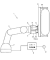
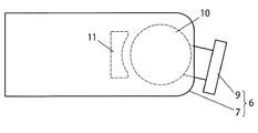
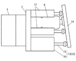
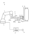
図1に示したように、本実施形態による搬送ロボット1は、ロボット基台2と、ロボット基台2に基端部が接続されたロボットアーム3と、ロボットアーム3の動作を制御するロボット制御装置4と、を備えており、これにより六軸多関節型ロボットが構成されている。
As shown in FIG. 1, the
なお、本発明の適用対象となるロボットは、六軸多関節型ロボットに限られず、ロボットアームを備えた各種のロボットに本発明を適用することができる。 Note that the robot to which the present invention is applied is not limited to a six-axis articulated robot, and the present invention can be applied to various robots including a robot arm.
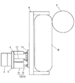
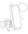
ロボットアーム3の先端(第6軸)にはベース部材5が取り付けられており、このベース部材5には、図2および図3に示したように、接続装置6の本体部7が取り付けられている。図1に示したように、接続装置6およびベース部材5を介して、ワークWを保持するためのワーク保持部材8がロボットアーム3に接続されている。
A
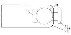
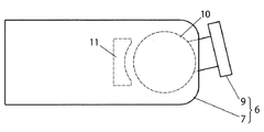
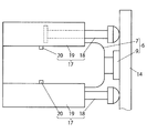
図4乃至図6に示したように、接続装置6は、本体部7と、本体部7から突出し、ワーク保持部材8に先端が固定された軸部9と、本体部7に対して軸部9を傾動可能に支持するための球状軸受(軸部支持部)10と、球状軸受10の回転動作を解放可能に固定することにより、軸部9を解放可能に固定して傾動不能とするためのロック機構11と、を有する。
As shown in FIGS. 4 to 6, the
球状軸受10は、接続装置6の本体部7に関してワーク保持部材8を傾動可能に支持するための支持手段を構成している。
The spherical bearing 10 constitutes a support means for supporting the
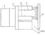
ベース部材5には、さらに、接続装置6の本体部7に関してワーク保持部材8を所定の姿勢に解放可能に維持するための姿勢維持装置12が設けられている。姿勢維持装置12は、ワーク保持部材8を、図1に示したワーク取付け姿勢(所定の姿勢)に維持するためのものである。具体的には、ワーク取付け姿勢におけるベース部材5の前面下部に、左右一対の押圧用エアシリンダ13が取り付けられており、これら左右一対の押圧用エアエアシリンダ13から成る押圧手段が、姿勢維持手段12を構成している。
The
押圧用エアシリンダ13は、ワーク保持部材8の背面に取り付けられた被押圧板14に先端が当接されるピストン部15と、ピストン部15を駆動するためのシリンダ本体部16と、を有する。押圧用エアシリンダ13から成る押圧手段は、被押圧板14を押圧して、ワーク保持部材8をワーク取付け姿勢(所定の姿勢)に維持する。具体的には、押圧用エアシリンダ13から成る押圧手段は、重力の作用によって傾動しようとするワーク保持部材8を支持してワーク取付け姿勢に維持するように構成されている。
The
なお、本発明の姿勢維持手段を構成する押圧手段は、上述したエアシリンダに限定されるものではなく、電動シリンダや油圧シリンダでも良いし、必ずしもシリンダ部材に限定されるものでもない。 The pressing means constituting the attitude maintaining means of the present invention is not limited to the above-described air cylinder, but may be an electric cylinder or a hydraulic cylinder, and is not necessarily limited to a cylinder member.
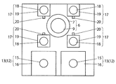
図2および図3に示したように、本実施形態による搬送ロボット1は、接続装置6の本体部7に関してワーク保持部材8が傾動したことを検出するための検出手段を有し、この検出手段は、接続装置6の周囲に設けられた4つの検出用エアシリンダ17から成る。
As shown in FIG. 2 and FIG. 3, the
検出用エアシリンダ17は、ワーク保持部材8の背面に取り付けられた被押圧板14に先端が当接されるピストン部18と、ピストン部18を駆動するためのシリンダ本体部19と、シリンダ本体部19に関するピストン部18の位置を検出するための位置検出センサ20と、を有する。位置検出センサ20の検出信号は、ロボット制御装置4に伝送される。
The
また、図1に示したように本実施形態による搬送ロボット1は、人の接近を検出するための人感センサ21を有する。この人感センサ21は、ロボット本体に人が接近したことを検出し、その検出信号はロボット制御装置4に伝送される。
As shown in FIG. 1, the
次に、本実施形態による搬送ロボットの作用について図面を参照して説明する。 Next, the operation of the transport robot according to the present embodiment will be described with reference to the drawings.
図1に示したように、ワーク保持部材8がワークWを保持した状態で、ロボット制御装置4によってロボットアーム3を駆動して、ワークWを所定の位置へ搬送する。
As shown in FIG. 1, in a state where the
このとき、押圧用エアシリンダ13には圧縮空気が供給されており、そのピストン部15の先端が、ワーク保持部材8の背面の被押圧板14に当接されている。これにより、重力の作用によって傾動しようとするワーク保持部材8が支持されて、図1に示したワーク取付け姿勢に維持される。ここで、押圧用エアシリンダ13による押圧力は、重力の作用により傾動方向に作用する力と、ほぼ釣り合うように設定されいる。
At this time, compressed air is supplied to the
また、接続装置6のロック機構11はロック状態とされており、これにより、ワーク保持部材8をワーク取付け姿勢に維持するための剛性が高められている。その結果、ワーク搬送時のロボットアーム3の動作速度を増大させることができる。
Further, the
また、検出用エアシリンダ17には圧縮空気が供給されており、そのピストン部18の先端が、ワーク保持部材8の背面の被押圧板14に当接されている。ここで、ワーク保持部材8の姿勢維持は押圧用エアシリンダ13によって確保されているので、4つの検出用エアシリンダ17においては、重力によるワーク保持部材の傾動方向の力が作用せず、均等の押圧力が付与されている。
Compressed air is supplied to the
そして、搬送ロボット1によるワーク搬送作業中にロボット本体に人が接近すると、人感センサ21がこれを検出して、その検出信号がロボット制御装置4に伝送される。
Then, when a person approaches the robot body during the work transfer operation by the
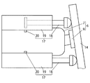
人感センサ21からの検出信号を受信したロボット制御装置4は、接続装置6のロック機構11を操作して、そのロック状態(図4)を非ロック状態(図5、図6)に切り替えると共に、ロボットアーム3によるワーク搬送動作の速度を低下させる(安全動作の予備動作)。
The
この状態においてワーク搬送動作を行っている最中に、図7に示したように人Pや障害物がワークW(またはワーク保持部材)に接触すると、図8に示したようにワーク保持部材8が傾動する。これにより、ワーク保持部材8の背面の被押圧板14は、図9に示した直立状態から、図10に示した傾斜状態へと変位する。
When a person P or an obstacle comes into contact with the workpiece W (or workpiece holding member) as shown in FIG. 7 during the workpiece transfer operation in this state, the
被押圧板14が直立状態から傾斜状態へと変位することにより、4つの検出用エアシリンダ17のうちの少なくとも1つ(本例では下段の左右2つの検出用エアシリンダ)において、そのピストン部18が押し込まれる。これにより、ピストン部18が、図11に示した突出位置から図12に示した引込み位置へと移動し、このピストン部18の変位が、シリンダ本体部19に設けた位置検出センサ20によって検出される。
When the pressed
なお、4つの検出用エアシリンダ17が接続装置6の周囲に等角度(90度)間隔で配置されているので、ワーク保持部材8の傾動動作の方向に関わらず、その傾動動作を確実に検出することができる。
Since the four
ロボット制御装置4は、位置検出センサ20からの検出信号を受信すると、ロボットアーム3に安全動作を行わせる。この安全動作の内容は、例えば、ロボットアーム3の動作を停止させること、ロボットアーム3の動作速度を低下させること、検出信号受信時よりも前の時点における位置へロボットアーム3を移動させること、或いはこれらの動作の組み合わせである。
When receiving the detection signal from the
また、その他の安全動作として、ロボット制御装置4は、位置検出センサ20からの検出信号に応じて、押圧用エアシリンダ13を操作して、その押圧力を解除する。これにより、姿勢維持装置12によるワーク保持部材8の姿勢維持機能が無効とされ、ワーク保持部材8を接続装置6の本体部7に関して傾動可能な状態となる。また、検出用エアシリンダ17を操作して、その押圧力を解除するようにしても良い。
As another safe operation, the
押圧用エアシリンダ13や検出用エアシリンダ17の押圧力を解除することにより、ワーク保持部材8をその取付け姿勢に維持するための剛性が低下するので、ワークWやワーク保持部材8に接触した人や障害物に対してロボットアーム3から作用する力を緩和することができる。
By releasing the pressing force of the
上記の通り安全動作が行われた後、当該作業現場における安全状態の確保が確認されたら、ロボット制御装置4によって押圧用エアシリンダ13および検出用エアシリンダ17を操作して、それらの押圧力を復帰させる。これにより、図13に示したように重力の作用によって傾斜していたワーク保持部材8が、押圧用エアシリンダ13のピストン部15によって押圧されて、図1に示したワーク取付け姿勢(直立状態)へと復帰される。
After the safety operation is performed as described above, when it is confirmed that the safety state is secured at the work site, the
以上述べたように本実施形態による搬送ロボット1によれば、ワーク搬送時のワーク保持部材8の姿勢を、押圧用エアシリンダ13から成る姿勢維持装置12によって維持すると共に、検出用エアシリンダ17からなる簡単な構成を有する検出手段によってワーク保持部材8の傾動動作を検出するようにしたので、従来のようなロボットの複雑な制御を必要とせずに、人とロボットとの協調作業の安全性を確保することができる。
As described above, according to the
次に、本発明の他の実施形態による搬送ロボットについて、図14乃至図17を参照して説明する。なお、上述した実施形態と同一の部材には同一の符号を付して説明を省略する。 Next, a transfer robot according to another embodiment of the present invention will be described with reference to FIGS. In addition, the same code | symbol is attached | subjected to the member same as embodiment mentioned above, and description is abbreviate | omitted.
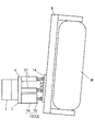
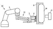
図14に示したように、本実施形態による搬送ロボット30は、ロボットアーム3の先端に設けられたフローティングユニット31を有する。図1に示した実施形態においては、ロボットアーム3の先端に接続装置6を直接的に取り付けるようにしたが、図14に示した本実施形態においては、接続装置6は、フローティングユニット31を介してロボットアーム3に装着されている。
As shown in FIG. 14, the
フローティングユニット31は、ロボットアーム3に関する接続装置6の水平方向への移動を可能にする水平移動機構32と、接続装置6を上方に向けて弾発的に支持して接続装置6の上下方向への移動を可能とする垂直移動機構33とを有する。
The floating
垂直移動機構33は、ロボットアーム3の先端(第6軸)に取り付けられた固定部34と、この固定部34に基端部が回転自在に接続された平行リンク35と、平行リンク35の先端部に回転自在に接続された昇降可動部36と、を有する。平行リンク35は、弾発手段(図示を省略)によって、昇降可動部36を上方に移動させる方向に付勢されている。
The
水平移動機構32は、垂直移動機構33の昇降稼働部36に水平方向にスライド自在に設けられた水平移動部材37を有する。水平移動部材37の先端に、接続装置6が設けられたベース部材5が取り付けられている。
The
ワーク保持装置8、ワークW等に作用する重力により平行リンク35に加えられる下向きの力は、弾発手段による弾発力によって相殺される。
The downward force applied to the
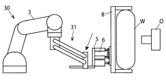
図14に示した搬送ロボット30によってワークWを所定の位置に搬送して、そこに取り付ける際には、ロボット制御装置4によってロボットアーム3を駆動して、図15に示したようにワークWをその取付け対象物Oの近傍に搬送する。
When the work W is transported to a predetermined position by the
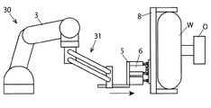
この状態から、図16に示したように、作業員が手作業にて、ワークWを取付け対象物Oに対して上下方向の位置合わせを行い、また、図17に示したように、水平方向の位置合わせを行う。このとき、ワークW等の重量は、フローティングユニット31の弾発手段によって支持されているので、作業員への負荷を大幅に軽減することができる。
From this state, as shown in FIG. 16, the worker manually aligns the workpiece W with respect to the mounting object O in the vertical direction, and as shown in FIG. 17, the horizontal direction Perform position alignment. At this time, since the weight of the workpiece W or the like is supported by the elastic means of the floating
このように本実施形態による搬送ロボット30は、ワーク搬送作業の最終段階において作業員による手作業が行われることを想定したものであり、作業員の安全確保が重要であるところ、上述したように、ワーク搬送時のワーク保持部材8の姿勢を姿勢維持装置12によって維持すると共に、検出用エアシリンダ17からなる簡単な構成を有する検出手段によってワーク保持部材8の傾動動作を検出するようにしたので、従来の技術のようなロボットの複雑な制御を必要とせずに、人とロボットとの協調作業の安全性を確保することができる。
As described above, the
1、30 搬送ロボット
2 ロボット基台
3 ロボットアーム
4 ロボット制御装置
5 ベース部材
6 接続装置
7 接続装置の本体部
8 ワーク保持部材
9 接続装置の軸部
10 接続装置の球状軸受
11 接続装置のロック機構
12 姿勢維持装置
13 押圧用エアシリンダ(押圧手段)
14 被押圧板
15 押圧用エアシリンダのピストン部
16 押圧用エアシリンダのシリンダ本体部
17 検出用エアシリンダ(検出手段)
18 検出用エアシリンダのピストン部
19 検出用エアシリンダのシリンダ本体部
20 検出用エアシリンダの位置検出センサ
21 人感センサ
31 フローティングユニット
32 フローティングユニットの水平移動機構
33 フローティングユニットの垂直移動機構
34 垂直移動機構の固定部
35 垂直移動機構の平行リンク
36 垂直移動機構の昇降稼働部
O ワークの取付け対象物
W ワーク
DESCRIPTION OF
14
DESCRIPTION OF
Claims (11)
ロボットアームと、
前記ワークを保持するためのワーク保持部材と、
前記ワーク保持部材を前記ロボットアームに接続するための接続装置であって、前記接続装置の本体部に関して前記ワーク保持部材を傾動可能に支持するための支持手段を有する、接続装置と、
前記接続装置の前記本体部に関して前記ワーク保持部材を所定の姿勢に維持するための姿勢維持装置と、
前記接続装置の前記本体部に関して前記ワーク保持部材が傾動したことを検出するための検出手段と、
前記ロボットアームを制御するためのロボット制御装置であって、前記接続装置の前記本体部に関して前記ワーク保持部材が傾動したことを前記検出手段によって検出した場合に前記ロボットアームに安全動作を行わせる、ロボット制御装置と、を備えた搬送ロボット。 A transfer robot for transferring a workpiece,
A robot arm,
A workpiece holding member for holding the workpiece;
A connection device for connecting the work holding member to the robot arm, the connection device having support means for tiltably supporting the work holding member with respect to a main body portion of the connection device;
A posture maintaining device for maintaining the workpiece holding member in a predetermined posture with respect to the main body portion of the connection device;
Detecting means for detecting that the work holding member is tilted with respect to the main body of the connecting device;
A robot control device for controlling the robot arm, wherein the robot arm performs a safe operation when the detection means detects that the workpiece holding member is tilted with respect to the main body of the connection device; And a robot controller.
前記ロボット制御装置は、前記人感センサからの人の接近に関する検出信号に基づいて、前記接続装置の前記ロック機構をロック状態から非ロック状態に切り替える、請求項3記載の搬送ロボット。 A human sensor for detecting the approach of a person;
The transfer robot according to claim 3, wherein the robot control device switches the lock mechanism of the connection device from a locked state to an unlocked state based on a detection signal regarding the approach of a person from the human sensor.
前記押圧用シリンダ部材は、前記ワーク保持部材または前記ワーク保持部材に取り付けられた他の部材に先端が当接されるピストン部と、前記ピストン部を駆動するためのシリンダ本体部と、を有する、請求項5または6に記載の搬送ロボット。 The pressing means has a pressing cylinder member,
The pressing cylinder member has a piston portion whose tip is in contact with the workpiece holding member or another member attached to the workpiece holding member, and a cylinder body portion for driving the piston portion. The transfer robot according to claim 5 or 6.
前記検出用シリンダ部材は、前記ワーク保持部材または前記ワーク保持部材に取り付けられた他の部材に先端が当接されるピストン部と、前記ピストン部を駆動するためのシリンダ本体部と、前記シリンダ本体部に関する前記ピストン部の位置を検出するための位置検出センサと、を有する、請求項1乃至7のいずれか一項に記載の搬送ロボット。 The detection means has a detection cylinder member provided in the vicinity of the connection device,
The detection cylinder member includes a piston portion whose tip is in contact with the workpiece holding member or another member attached to the workpiece holding member, a cylinder body portion for driving the piston portion, and the cylinder body The position detection sensor for detecting the position of the said piston part regarding a part, The conveyance robot as described in any one of Claims 1 thru | or 7.
前記接続装置は、前記フローティングユニットを介して前記ロボットアームに装着されており、
前記フローティングユニットは、少なくとも、前記ロボットアームに関する前記接続装置の水平方向への移動を可能とする、請求項1乃至9のいずれか一項に記載の搬送ロボット。 A floating unit provided at the tip of the robot arm;
The connection device is attached to the robot arm via the floating unit,
The transfer robot according to any one of claims 1 to 9, wherein the floating unit enables at least the horizontal movement of the connection device related to the robot arm.
The floating unit enables the connection device with respect to the robot arm to move in the horizontal direction, and elastically supports the connection device upward to allow the connection device to move in the vertical direction. The transfer robot according to claim 10.
Priority Applications (1)
| Application Number | Priority Date | Filing Date | Title |
|---|---|---|---|
| JP2015131428A JP2017013169A (en) | 2015-06-30 | 2015-06-30 | Transfer robot |
Applications Claiming Priority (1)
| Application Number | Priority Date | Filing Date | Title |
|---|---|---|---|
| JP2015131428A JP2017013169A (en) | 2015-06-30 | 2015-06-30 | Transfer robot |
Publications (1)
| Publication Number | Publication Date |
|---|---|
| JP2017013169A true JP2017013169A (en) | 2017-01-19 |
Family
ID=57828658
Family Applications (1)
| Application Number | Title | Priority Date | Filing Date |
|---|---|---|---|
| JP2015131428A Pending JP2017013169A (en) | 2015-06-30 | 2015-06-30 | Transfer robot |
Country Status (1)
| Country | Link |
|---|---|
| JP (1) | JP2017013169A (en) |
Cited By (3)
| Publication number | Priority date | Publication date | Assignee | Title |
|---|---|---|---|---|
| JP2019042871A (en) * | 2017-09-01 | 2019-03-22 | 川崎重工業株式会社 | Robot system |
| CN119589364A (en) * | 2024-12-28 | 2025-03-11 | 安徽隆威汽车零部件有限公司 | A rubber buffer block press-fitting device |
| WO2025115866A1 (en) * | 2023-12-01 | 2025-06-05 | Smc株式会社 | Compliance unit |
Citations (4)
| Publication number | Priority date | Publication date | Assignee | Title |
|---|---|---|---|---|
| JPS6071592U (en) * | 1983-10-24 | 1985-05-20 | 株式会社小松製作所 | robot equipment |
| JPH0423283U (en) * | 1990-06-15 | 1992-02-26 | ||
| JP2006142416A (en) * | 2004-11-17 | 2006-06-08 | Honda Motor Co Ltd | Floating lock device |
| JP2015000470A (en) * | 2013-06-18 | 2015-01-05 | トヨタ自動車株式会社 | Robot control apparatus and robot control method |
-
2015
- 2015-06-30 JP JP2015131428A patent/JP2017013169A/en active Pending
Patent Citations (4)
| Publication number | Priority date | Publication date | Assignee | Title |
|---|---|---|---|---|
| JPS6071592U (en) * | 1983-10-24 | 1985-05-20 | 株式会社小松製作所 | robot equipment |
| JPH0423283U (en) * | 1990-06-15 | 1992-02-26 | ||
| JP2006142416A (en) * | 2004-11-17 | 2006-06-08 | Honda Motor Co Ltd | Floating lock device |
| JP2015000470A (en) * | 2013-06-18 | 2015-01-05 | トヨタ自動車株式会社 | Robot control apparatus and robot control method |
Cited By (4)
| Publication number | Priority date | Publication date | Assignee | Title |
|---|---|---|---|---|
| JP2019042871A (en) * | 2017-09-01 | 2019-03-22 | 川崎重工業株式会社 | Robot system |
| JP7011910B2 (en) | 2017-09-01 | 2022-01-27 | 川崎重工業株式会社 | Robot system |
| WO2025115866A1 (en) * | 2023-12-01 | 2025-06-05 | Smc株式会社 | Compliance unit |
| CN119589364A (en) * | 2024-12-28 | 2025-03-11 | 安徽隆威汽车零部件有限公司 | A rubber buffer block press-fitting device |
Similar Documents
| Publication | Publication Date | Title |
|---|---|---|
| US10471603B2 (en) | System for conveying workpiece having external force monitoring function | |
| JP4508263B2 (en) | Power assist device and control method thereof | |
| JP5480246B2 (en) | Working apparatus and working method | |
| CN101518901B (en) | Power assist apparatus and control method thereof | |
| JP5621433B2 (en) | Robot and control method thereof | |
| JP2017013169A (en) | Transfer robot | |
| US20130248477A1 (en) | Movement device configured for moving a payload | |
| CN109311642A (en) | mobile crane | |
| JP2010241518A (en) | Cargo handling machine and method of controlling the same | |
| JP2012086310A (en) | Load conveying robot | |
| CN107428012A (en) | Manipulator, the control method of manipulator, the method for carrying of the installation method of workpiece and workpiece | |
| JP2012110992A (en) | Cargo carrying arm and cargo carrying robot with cargo carrying arm | |
| KR102248155B1 (en) | Movable working-tower appratus for preventing overturn at porthole | |
| JP6445114B2 (en) | Work conveying method system having external force monitoring function | |
| JP2009184826A (en) | forklift | |
| JP2012086311A (en) | Cargo conveying robot | |
| JP2017506296A (en) | Truck-mounted concrete pump | |
| KR20070032706A (en) | Control method of legged mobile robot | |
| JP2023125580A (en) | Conveyor system | |
| CN108867747B (en) | Construction machinery working boom automatic return adjustment system and method and construction machinery | |
| JP5131113B2 (en) | Transfer device and transfer method | |
| JP4669801B2 (en) | Non-inertial type load handling device | |
| JP6357392B2 (en) | Steel plate transfer device | |
| WO2019007448A1 (en) | A method for a heavy load handling and a device for a heavy load handling | |
| CN223813103U (en) | Remove system |
Legal Events
| Date | Code | Title | Description |
|---|---|---|---|
| A621 | Written request for application examination |
Free format text: JAPANESE INTERMEDIATE CODE: A621 Effective date: 20180629 |
|
| A977 | Report on retrieval |
Free format text: JAPANESE INTERMEDIATE CODE: A971007 Effective date: 20190625 |
|
| A131 | Notification of reasons for refusal |
Free format text: JAPANESE INTERMEDIATE CODE: A131 Effective date: 20190702 |
|
| A601 | Written request for extension of time |
Free format text: JAPANESE INTERMEDIATE CODE: A601 Effective date: 20190902 |
|
| A02 | Decision of refusal |
Free format text: JAPANESE INTERMEDIATE CODE: A02 Effective date: 20200106 |