JP2017013109A - Manufacturing method for rolling bearing unit - Google Patents
Manufacturing method for rolling bearing unit Download PDFInfo
- Publication number
- JP2017013109A JP2017013109A JP2015134992A JP2015134992A JP2017013109A JP 2017013109 A JP2017013109 A JP 2017013109A JP 2015134992 A JP2015134992 A JP 2015134992A JP 2015134992 A JP2015134992 A JP 2015134992A JP 2017013109 A JP2017013109 A JP 2017013109A
- Authority
- JP
- Japan
- Prior art keywords
- roll
- axial direction
- hub
- hub body
- central axis
- Prior art date
- Legal status (The legal status is an assumption and is not a legal conclusion. Google has not performed a legal analysis and makes no representation as to the accuracy of the status listed.)
- Granted
Links
Images


Classifications
-
- B—PERFORMING OPERATIONS; TRANSPORTING
- B21—MECHANICAL METAL-WORKING WITHOUT ESSENTIALLY REMOVING MATERIAL; PUNCHING METAL
- B21D—WORKING OR PROCESSING OF SHEET METAL OR METAL TUBES, RODS OR PROFILES WITHOUT ESSENTIALLY REMOVING MATERIAL; PUNCHING METAL
- B21D53/00—Making other particular articles
- B21D53/10—Making other particular articles parts of bearings; sleeves; valve seats or the like
-
- B—PERFORMING OPERATIONS; TRANSPORTING
- B21—MECHANICAL METAL-WORKING WITHOUT ESSENTIALLY REMOVING MATERIAL; PUNCHING METAL
- B21J—FORGING; HAMMERING; PRESSING METAL; RIVETING; FORGE FURNACES
- B21J9/00—Forging presses
- B21J9/02—Special design or construction
- B21J9/025—Special design or construction with rolling or wobbling dies
-
- B—PERFORMING OPERATIONS; TRANSPORTING
- B21—MECHANICAL METAL-WORKING WITHOUT ESSENTIALLY REMOVING MATERIAL; PUNCHING METAL
- B21K—MAKING FORGED OR PRESSED METAL PRODUCTS, e.g. HORSE-SHOES, RIVETS, BOLTS OR WHEELS
- B21K1/00—Making machine elements
- B21K1/28—Making machine elements wheels; discs
- B21K1/30—Making machine elements wheels; discs with gear-teeth
-
- B—PERFORMING OPERATIONS; TRANSPORTING
- B21—MECHANICAL METAL-WORKING WITHOUT ESSENTIALLY REMOVING MATERIAL; PUNCHING METAL
- B21K—MAKING FORGED OR PRESSED METAL PRODUCTS, e.g. HORSE-SHOES, RIVETS, BOLTS OR WHEELS
- B21K1/00—Making machine elements
- B21K1/28—Making machine elements wheels; discs
- B21K1/40—Making machine elements wheels; discs hubs
-
- B—PERFORMING OPERATIONS; TRANSPORTING
- B21—MECHANICAL METAL-WORKING WITHOUT ESSENTIALLY REMOVING MATERIAL; PUNCHING METAL
- B21K—MAKING FORGED OR PRESSED METAL PRODUCTS, e.g. HORSE-SHOES, RIVETS, BOLTS OR WHEELS
- B21K1/00—Making machine elements
- B21K1/76—Making machine elements elements not mentioned in one of the preceding groups
- B21K1/762—Coupling members for conveying mechanical motion, e.g. universal joints
- B21K1/765—Outer elements of coupling members
-
- B—PERFORMING OPERATIONS; TRANSPORTING
- B23—MACHINE TOOLS; METAL-WORKING NOT OTHERWISE PROVIDED FOR
- B23B—TURNING; BORING
- B23B51/00—Tools for drilling machines
-
- B—PERFORMING OPERATIONS; TRANSPORTING
- B60—VEHICLES IN GENERAL
- B60B—VEHICLE WHEELS; CASTORS; AXLES FOR WHEELS OR CASTORS; INCREASING WHEEL ADHESION
- B60B27/00—Hubs
-
- B—PERFORMING OPERATIONS; TRANSPORTING
- B60—VEHICLES IN GENERAL
- B60B—VEHICLE WHEELS; CASTORS; AXLES FOR WHEELS OR CASTORS; INCREASING WHEEL ADHESION
- B60B27/00—Hubs
- B60B27/0015—Hubs for driven wheels
- B60B27/0021—Hubs for driven wheels characterised by torque transmission means from drive axle
- B60B27/0031—Hubs for driven wheels characterised by torque transmission means from drive axle of the axial type, e.g. front teeth
-
- B—PERFORMING OPERATIONS; TRANSPORTING
- B60—VEHICLES IN GENERAL
- B60B—VEHICLE WHEELS; CASTORS; AXLES FOR WHEELS OR CASTORS; INCREASING WHEEL ADHESION
- B60B27/00—Hubs
- B60B27/0015—Hubs for driven wheels
- B60B27/0036—Hubs for driven wheels comprising homokinetic joints
-
- F—MECHANICAL ENGINEERING; LIGHTING; HEATING; WEAPONS; BLASTING
- F16—ENGINEERING ELEMENTS AND UNITS; GENERAL MEASURES FOR PRODUCING AND MAINTAINING EFFECTIVE FUNCTIONING OF MACHINES OR INSTALLATIONS; THERMAL INSULATION IN GENERAL
- F16C—SHAFTS; FLEXIBLE SHAFTS; ELEMENTS OR CRANKSHAFT MECHANISMS; ROTARY BODIES OTHER THAN GEARING ELEMENTS; BEARINGS
- F16C43/00—Assembling bearings
- F16C43/04—Assembling rolling-contact bearings
-
- F—MECHANICAL ENGINEERING; LIGHTING; HEATING; WEAPONS; BLASTING
- F16—ENGINEERING ELEMENTS AND UNITS; GENERAL MEASURES FOR PRODUCING AND MAINTAINING EFFECTIVE FUNCTIONING OF MACHINES OR INSTALLATIONS; THERMAL INSULATION IN GENERAL
- F16D—COUPLINGS FOR TRANSMITTING ROTATION; CLUTCHES; BRAKES
- F16D1/00—Couplings for rigidly connecting two coaxial shafts or other movable machine elements
- F16D1/06—Couplings for rigidly connecting two coaxial shafts or other movable machine elements for attachment of a member on a shaft or on a shaft-end
- F16D1/076—Couplings for rigidly connecting two coaxial shafts or other movable machine elements for attachment of a member on a shaft or on a shaft-end by clamping together two faces perpendicular to the axis of rotation, e.g. with bolted flanges
-
- B—PERFORMING OPERATIONS; TRANSPORTING
- B60—VEHICLES IN GENERAL
- B60B—VEHICLE WHEELS; CASTORS; AXLES FOR WHEELS OR CASTORS; INCREASING WHEEL ADHESION
- B60B27/00—Hubs
- B60B27/0005—Hubs with ball bearings
-
- B—PERFORMING OPERATIONS; TRANSPORTING
- B60—VEHICLES IN GENERAL
- B60B—VEHICLE WHEELS; CASTORS; AXLES FOR WHEELS OR CASTORS; INCREASING WHEEL ADHESION
- B60B27/00—Hubs
- B60B27/0078—Hubs characterised by the fixation of bearings
- B60B27/0084—Hubs characterised by the fixation of bearings caulking to fix inner race
-
- F—MECHANICAL ENGINEERING; LIGHTING; HEATING; WEAPONS; BLASTING
- F16—ENGINEERING ELEMENTS AND UNITS; GENERAL MEASURES FOR PRODUCING AND MAINTAINING EFFECTIVE FUNCTIONING OF MACHINES OR INSTALLATIONS; THERMAL INSULATION IN GENERAL
- F16C—SHAFTS; FLEXIBLE SHAFTS; ELEMENTS OR CRANKSHAFT MECHANISMS; ROTARY BODIES OTHER THAN GEARING ELEMENTS; BEARINGS
- F16C19/00—Bearings with rolling contact, for exclusively rotary movement
- F16C19/02—Bearings with rolling contact, for exclusively rotary movement with bearing balls essentially of the same size in one or more circular rows
- F16C19/14—Bearings with rolling contact, for exclusively rotary movement with bearing balls essentially of the same size in one or more circular rows for both radial and axial load
- F16C19/18—Bearings with rolling contact, for exclusively rotary movement with bearing balls essentially of the same size in one or more circular rows for both radial and axial load with two or more rows of balls
- F16C19/181—Bearings with rolling contact, for exclusively rotary movement with bearing balls essentially of the same size in one or more circular rows for both radial and axial load with two or more rows of balls with angular contact
- F16C19/183—Bearings with rolling contact, for exclusively rotary movement with bearing balls essentially of the same size in one or more circular rows for both radial and axial load with two or more rows of balls with angular contact with two rows at opposite angles
- F16C19/184—Bearings with rolling contact, for exclusively rotary movement with bearing balls essentially of the same size in one or more circular rows for both radial and axial load with two or more rows of balls with angular contact with two rows at opposite angles in O-arrangement
- F16C19/186—Bearings with rolling contact, for exclusively rotary movement with bearing balls essentially of the same size in one or more circular rows for both radial and axial load with two or more rows of balls with angular contact with two rows at opposite angles in O-arrangement with three raceways provided integrally on parts other than race rings, e.g. third generation hubs
-
- F—MECHANICAL ENGINEERING; LIGHTING; HEATING; WEAPONS; BLASTING
- F16—ENGINEERING ELEMENTS AND UNITS; GENERAL MEASURES FOR PRODUCING AND MAINTAINING EFFECTIVE FUNCTIONING OF MACHINES OR INSTALLATIONS; THERMAL INSULATION IN GENERAL
- F16C—SHAFTS; FLEXIBLE SHAFTS; ELEMENTS OR CRANKSHAFT MECHANISMS; ROTARY BODIES OTHER THAN GEARING ELEMENTS; BEARINGS
- F16C2226/00—Joining parts; Fastening; Assembling or mounting parts
- F16C2226/50—Positive connections
- F16C2226/52—Positive connections with plastic deformation, e.g. caulking or staking
-
- F—MECHANICAL ENGINEERING; LIGHTING; HEATING; WEAPONS; BLASTING
- F16—ENGINEERING ELEMENTS AND UNITS; GENERAL MEASURES FOR PRODUCING AND MAINTAINING EFFECTIVE FUNCTIONING OF MACHINES OR INSTALLATIONS; THERMAL INSULATION IN GENERAL
- F16C—SHAFTS; FLEXIBLE SHAFTS; ELEMENTS OR CRANKSHAFT MECHANISMS; ROTARY BODIES OTHER THAN GEARING ELEMENTS; BEARINGS
- F16C2226/00—Joining parts; Fastening; Assembling or mounting parts
- F16C2226/50—Positive connections
- F16C2226/60—Positive connections with threaded parts, e.g. bolt and nut connections
-
- F—MECHANICAL ENGINEERING; LIGHTING; HEATING; WEAPONS; BLASTING
- F16—ENGINEERING ELEMENTS AND UNITS; GENERAL MEASURES FOR PRODUCING AND MAINTAINING EFFECTIVE FUNCTIONING OF MACHINES OR INSTALLATIONS; THERMAL INSULATION IN GENERAL
- F16C—SHAFTS; FLEXIBLE SHAFTS; ELEMENTS OR CRANKSHAFT MECHANISMS; ROTARY BODIES OTHER THAN GEARING ELEMENTS; BEARINGS
- F16C2326/00—Articles relating to transporting
- F16C2326/01—Parts of vehicles in general
- F16C2326/02—Wheel hubs or castors
-
- F—MECHANICAL ENGINEERING; LIGHTING; HEATING; WEAPONS; BLASTING
- F16—ENGINEERING ELEMENTS AND UNITS; GENERAL MEASURES FOR PRODUCING AND MAINTAINING EFFECTIVE FUNCTIONING OF MACHINES OR INSTALLATIONS; THERMAL INSULATION IN GENERAL
- F16C—SHAFTS; FLEXIBLE SHAFTS; ELEMENTS OR CRANKSHAFT MECHANISMS; ROTARY BODIES OTHER THAN GEARING ELEMENTS; BEARINGS
- F16C35/00—Rigid support of bearing units; Housings, e.g. caps, covers
- F16C35/04—Rigid support of bearing units; Housings, e.g. caps, covers in the case of ball or roller bearings
- F16C35/06—Mounting or dismounting of ball or roller bearings; Fixing them onto shaft or in housing
- F16C35/063—Fixing them on the shaft
-
- F—MECHANICAL ENGINEERING; LIGHTING; HEATING; WEAPONS; BLASTING
- F16—ENGINEERING ELEMENTS AND UNITS; GENERAL MEASURES FOR PRODUCING AND MAINTAINING EFFECTIVE FUNCTIONING OF MACHINES OR INSTALLATIONS; THERMAL INSULATION IN GENERAL
- F16D—COUPLINGS FOR TRANSMITTING ROTATION; CLUTCHES; BRAKES
- F16D3/00—Yielding couplings, i.e. with means permitting movement between the connected parts during the drive
- F16D3/16—Universal joints in which flexibility is produced by means of pivots or sliding or rolling connecting parts
- F16D3/20—Universal joints in which flexibility is produced by means of pivots or sliding or rolling connecting parts one coupling part entering a sleeve of the other coupling part and connected thereto by sliding or rolling members
- F16D3/22—Universal joints in which flexibility is produced by means of pivots or sliding or rolling connecting parts one coupling part entering a sleeve of the other coupling part and connected thereto by sliding or rolling members the rolling members being balls, rollers, or the like, guided in grooves or sockets in both coupling parts
- F16D3/223—Universal joints in which flexibility is produced by means of pivots or sliding or rolling connecting parts one coupling part entering a sleeve of the other coupling part and connected thereto by sliding or rolling members the rolling members being balls, rollers, or the like, guided in grooves or sockets in both coupling parts the rolling members being guided in grooves in both coupling parts
- F16D2003/22326—Attachments to the outer joint member, i.e. attachments to the exterior of the outer joint member or to the shaft of the outer joint member
-
- F—MECHANICAL ENGINEERING; LIGHTING; HEATING; WEAPONS; BLASTING
- F16—ENGINEERING ELEMENTS AND UNITS; GENERAL MEASURES FOR PRODUCING AND MAINTAINING EFFECTIVE FUNCTIONING OF MACHINES OR INSTALLATIONS; THERMAL INSULATION IN GENERAL
- F16D—COUPLINGS FOR TRANSMITTING ROTATION; CLUTCHES; BRAKES
- F16D2250/00—Manufacturing; Assembly
- F16D2250/0023—Shaping by pressure
-
- F—MECHANICAL ENGINEERING; LIGHTING; HEATING; WEAPONS; BLASTING
- F16—ENGINEERING ELEMENTS AND UNITS; GENERAL MEASURES FOR PRODUCING AND MAINTAINING EFFECTIVE FUNCTIONING OF MACHINES OR INSTALLATIONS; THERMAL INSULATION IN GENERAL
- F16D—COUPLINGS FOR TRANSMITTING ROTATION; CLUTCHES; BRAKES
- F16D3/00—Yielding couplings, i.e. with means permitting movement between the connected parts during the drive
- F16D3/16—Universal joints in which flexibility is produced by means of pivots or sliding or rolling connecting parts
- F16D3/20—Universal joints in which flexibility is produced by means of pivots or sliding or rolling connecting parts one coupling part entering a sleeve of the other coupling part and connected thereto by sliding or rolling members
- F16D3/22—Universal joints in which flexibility is produced by means of pivots or sliding or rolling connecting parts one coupling part entering a sleeve of the other coupling part and connected thereto by sliding or rolling members the rolling members being balls, rollers, or the like, guided in grooves or sockets in both coupling parts
- F16D3/223—Universal joints in which flexibility is produced by means of pivots or sliding or rolling connecting parts one coupling part entering a sleeve of the other coupling part and connected thereto by sliding or rolling members the rolling members being balls, rollers, or the like, guided in grooves or sockets in both coupling parts the rolling members being guided in grooves in both coupling parts
- F16D3/226—Universal joints in which flexibility is produced by means of pivots or sliding or rolling connecting parts one coupling part entering a sleeve of the other coupling part and connected thereto by sliding or rolling members the rolling members being balls, rollers, or the like, guided in grooves or sockets in both coupling parts the rolling members being guided in grooves in both coupling parts the groove centre-lines in each coupling part lying on a cylinder co-axial with the respective coupling part
Abstract
Description
本発明は、例えば、等速ジョイントと組み合わせる事で、車輪駆動用軸受ユニットを構成する車輪支持用転がり軸受ユニットとして使用される、転がり軸受ユニットの製造方法に関する。 The present invention relates to a method for manufacturing a rolling bearing unit that is used as a wheel bearing rolling bearing unit that constitutes a wheel driving bearing unit, for example, in combination with a constant velocity joint.
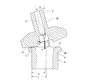
図5は、本発明の対象となる転がり軸受ユニットの1種である、車輪支持用転がり軸受ユニットを組み込んだ車輪駆動用軸受ユニットの従来構造の1例として、特許文献1に記載されたものを示している。この図5に示した車輪駆動用軸受ユニットは、車輪支持用転がり軸受ユニット1と、等速ジョイント用外輪2とを組み合わせて成る。このうちの車輪支持用転がり軸受ユニット1は、外輪3と、ハブ4と、複数個の転動体(図示の例では玉)5、5とを備える。
FIG. 5 shows an example of a conventional structure of a wheel driving bearing unit incorporating a wheel supporting rolling bearing unit, which is a kind of rolling bearing unit that is an object of the present invention, described in Patent Document 1. Show. The wheel drive bearing unit shown in FIG. 5 is a combination of a wheel support rolling bearing unit 1 and a constant velocity joint
このうちの外輪3は、外周面に静止側フランジ6を、内周面に複列の外輪軌道7a、7bを、それぞれ有する。又、前記ハブ4は、ハブ本体8と内輪9とを組み合わせて成る。このうちのハブ本体8は、外周面の軸方向片端寄り部分に回転側フランジ10を、同じく軸方向中間部に軸方向片側の内輪軌道11aを、同じく軸方向他端部に小径段部12を、中心部に中心孔13を、それぞれ有する。尚、本明細書及び特許請求の範囲で、軸方向に関して「片側」とは、自動車への組み付け状態で車両の幅方向外側を言い、図5の左側、図6の下側を言い、反対に、自動車への組み付け状態で車両の中央側となる、図5の右側、図6の上側を、軸方向に関して「他側」と言う。前記中心孔13の軸方向片端部には、結合部材であるボルト15の杆部16を所定の案内隙間を介して挿通可能な小径部14が存在する。又、前記内輪9は、外周面に軸方向他側の内輪軌道11bを有するもので、前記ハブ本体8の小径段部12に締り嵌めで外嵌されている。又、前記各転動体5、5は、前記両外輪軌道7a、7bと前記両内輪軌道11a、11bとの間に、両列毎に複数個ずつ転動自在に設けられている。又、この状態で、前記ハブ本体8の軸方向他端部に設けた円筒部19のうち、前記内輪9の軸方向他端開口から突出した部分を径方向外方に塑性変形させる事によりかしめ部20を形成している。そして、このかしめ部20により前記内輪9の軸方向他端面を抑え付ける事で、前記各転動体5、5に適正な予圧を付与している。又、前記かしめ部20の軸方向他端面には、円周方向に関する凹凸部であるハブ側フェイススプライン21を、全周に亙り形成している。尚、図示の例の場合、このハブ側フェイススプライン21の歯先面を、前記ハブ本体8の中心軸に対して直角な平面としている。
Of these, the outer ring 3 has a
又、前記等速ジョイント用外輪2は、カップ状のマウス部22と、このマウス部22の底部である端壁部23と、この端壁部23の中心部から軸方向片方に延出する円筒状の軸部24とを有すると共に、この軸部24の中心孔がねじ孔25である。又、前記端壁部23の軸方向片端面の外周寄り部分には、円周方向に関する凹凸部であるジョイント側フェイススプライン26を、全周に亙り形成している。尚、図示の例の場合、このジョイント側フェイススプライン26の歯先面を、前記等速ジョイント用外輪2の中心軸に対して直角な平面としている。又、前記ジョイント側フェイススプライン26の歯数を、前記ハブ側フェイススプライン21の歯数と同じとしている。
The constant velocity joint
そして、前記ハブ本体8と前記等速ジョイント用外輪2との中心軸同士を一致させた状態で、前記ハブ側、ジョイント側両フェイススプライン21、26同士を噛み合わせる事により、前記ハブ本体8と前記等速ジョイント用外輪2との間での回転力の伝達を可能としている。又、この状態で、前記ハブ本体8の中心孔13の小径部14に、軸方向片側からボルト15の杆部16を挿通すると共に、この杆部16の先端部に設けた雄ねじ部17を前記ねじ孔25に螺合し、更に締め付けている。これにより、前記ボルト15の頭部18と前記等速ジョイント用外輪2との間に前記ハブ本体8を挟持した状態で、これらハブ本体8と等速ジョイント用外輪2とを結合固定している。
Then, the
上述の様に構成する車輪駆動用軸受ユニットを車両に組み付ける際には、前記外輪3の静止側フランジ6を懸架装置に結合固定すると共に、前記ハブ本体8の回転側フランジ10に車輪(駆動輪)及びディスク等の制動用回転部材を支持固定する。又、エンジンによりトランスミッションを介して回転駆動される、図示しない駆動軸の先端部を、前記等速ジョイント用外輪2の内側に設けた等速ジョイント用内輪27の内側にスプライン係合させる。自動車の走行時には、この等速ジョイント用内輪27の回転を、複数のボール28を介して、前記等速ジョイント用外輪2及びハブ本体8に伝達し、前記車輪を回転駆動する。
When the wheel drive bearing unit configured as described above is assembled to a vehicle, the
上述の様に構成する車輪駆動用軸受ユニットを構成する車輪支持用転がり軸受ユニット1を組み立てる際には、先ず、前記ハブ本体8の周囲に前記外輪3を配置すると共に、前記両外輪軌道7a、7bのうち、軸方向片側の外輪軌道7aと、前記軸方向片側の内輪軌道11aとの間に前記各転動体5、5を、軸方向片側の保持器29aにより保持した状態で設ける。次に、前記内輪9の外周面に形成した軸方向他側の内輪軌道11bの周囲に前記各転動体5、5を、軸方向他側の保持器29bにより保持した状態で設置し、この状態で前記内輪9を、前記ハブ本体8の軸方向他端部に形成した小径段部12に締り嵌めで外嵌する。そして、この外嵌作業に伴い、前記軸方向他側の保持器29bにより保持した(軸方向他側列の)前記各転動体5、5の転動面を、前記外輪3の軸方向他端寄り部分の内周面に形成した軸方向他側の外輪軌道7bに当接させる。次いで、前記ハブ本体8の軸方向他端部に形成した円筒部19を径方向外方に塑性変形させ、前記かしめ部20を形成する。そして、このかしめ部20により前記内輪9の軸方向他端面を軸方向に抑え付ける事で、この内輪9を前記ハブ本体8に固定する。
When assembling the wheel support rolling bearing unit 1 constituting the wheel drive bearing unit configured as described above, first, the outer ring 3 is disposed around the
更に、図6に示す様に、前記かしめ部20の軸方向他端面に、前記ハブ本体8の中心軸(前記車輪支持用転がり軸受ユニット1の中心軸)αに対し所定角度θだけ傾斜した中心軸βを有するロール30を用いて揺動鍛造を施す事により、前記ハブ側フェイススプライン21を形成する。尚、前記図6は、前記車輪支持用転がり軸受ユニット1を構成する各部材のうち、ハブ本体8以外の部材(外輪3、転動体5、5及び内輪9等)を省略して示している。前記ロール30の先端面(図6の下端面)は、凹部34と凸部33、33(図9参照)とを全周に亙って交互に配置して成る加工面31としている。この様なロール30の加工面31を前記かしめ部20の軸方向他端面に向けて押し付けた状態で、このロール30を、前記ハブ本体8の中心軸αを中心として回転させる。ここで、このロール30は、自身の中心軸βを中心として回転可能に支持されている。従って、前記かしめ部20の軸方向他端面に前記ハブ側フェイススプライン21(となるべき円周方向に関する凹凸部)が形成される以前の状態では、前記ロール30を、前記ハブ本体8の中心軸αを中心として回転させると、前記加工面31に設けた凸部33、33の先端面と前記かしめ部20の軸方向他端面との摩擦係合に基づいて、前記ロール30が自身の中心軸βを中心として回転(自転)する。一方、前記ハブ側フェイススプライン21がある程度形成された(このハブ側フェイススプライン21の歯丈がある程度大きくなった)後は、前記ロール30を、前記ハブ本体8の中心軸αを中心として回転させると、前記加工面31を構成する凹部34及び凸部33、33と前記ハブ側フェイススプライン21との係合(噛合)に基づいて、前記ロール30が自転する。この様な構成により、前記ロール30の加工面31を前記かしめ部20の軸方向他端面に向けて押し付けて、このかしめ部20を塑性変形させる事により、このかしめ部20の軸方向他端面に前記ハブ側フェイススプライン21を形成し、更に、このハブ側フェイススプライン21の歯丈を大きくして、加工を完了する。
Further, as shown in FIG. 6, a center inclined at a predetermined angle θ with respect to the central axis (the central axis of the wheel supporting rolling bearing unit 1) α of the
上述の様な車輪支持用転がり軸受ユニット1の製造方法は、この車輪支持用転がり軸受ユニット1の耐久性を確保しつつ、製造コストを抑える面からは改良の余地がある。即ち、前記ハブ側フェイススプライン21を形成する作業(揺動鍛造)は、前記ロール30の加工面31を前記かしめ部20の軸方向他端面に大きな力(押付力)Fで押し付けた状態で、前記ロール30を、前記ハブ本体8の中心軸αを中心に回転させる事により行う。この様な揺動鍛造の際に、このハブ本体8の中心軸αに対する前記ロール30の中心軸βの傾斜角度θが小さいと、このロール30の加工面31と、前記かしめ部20の軸方向他端面との当接面積、即ち、この加工面31を構成する凸部33、33の先端面と、前記かしめ部20の軸方向他端面の当接面積が大きくなる。この結果、前記各凸部33、33の先端面から前記かしめ部20の軸方向他端面(のうち、前記ハブ側フェイススプライン21の歯底となるべき部分)に加わる荷重(前記各凸部33、33の先端面と前記かしめ部20の軸方向他端面との当接面圧)が小さくなる。従って、前記傾斜角度θが小さい場合には、前記押付力Fを大きくして、前記各凸部33、33の先端面から前記かしめ部20の軸方向他端面に加わる荷重を確保する必要がある。図7は、この傾斜角度θと、前記押付力Fの最大値との関係を示している。この様な図7から明らかな様に、この傾斜角度θが5度である場合には、この傾斜角度θが15度である場合の2倍程度の押付力Fが必要となる。この押付力Fを大きくすると、前記揺動鍛造に用いる加工装置が大型化し、これによって製造コストが増大する。
The manufacturing method of the wheel-supporting rolling bearing unit 1 as described above has room for improvement in terms of reducing the manufacturing cost while ensuring the durability of the wheel-supporting rolling bearing unit 1. That is, the operation of forming the hub-side face spline 21 (oscillating forging) is performed in a state where the processed
一方、前記傾斜角度θが大きいと、前記ハブ側フェイススプライン21を構成する歯32の歯面(歯の側面)の断面形状の真直度が低下する。この理由について、次に説明する。ロール30の加工面31を構成する凸部33、33の数と、ハブ側フェイススプライン21を構成する歯32の歯数とを同じとし、かしめ部20の軸方向他端面に揺動鍛造を施す際に、前記加工面31とこのかしめ部20の軸方向他端面との係合部で円周方向の滑りが発生してないと仮定すると、前記ロール30の加工面31上の任意の点Pは、閉ループ状の軌跡を描く。前記揺動鍛造の際に、この点Pが描く軌跡について、図6を参照しつつ説明する。
On the other hand, when the inclination angle θ is large, the straightness of the cross-sectional shape of the tooth surfaces (tooth side surfaces) of the
先ず、前記点Pが、前記かしめ部20の軸方向他端面との係合部上(図6の点P0)にあると仮定する。原点をハブ本体8の中心軸αと前記ロール30の中心軸βとの交点とし、互いに直交するx1軸、y1軸、z1軸のうちのy1軸を図6の表裏方向に、z1軸を前記ロール30の中心軸βに、それぞれ一致させた自転座標系(x1,y1,z1)で、前記点P0の座標P0(x1,y1,z1)は、次の(1)式で表される。

前記揺動鍛造の際、前記ロール30は、自身の中心軸β(z1軸)を中心に回転(自転)する。前記点P0を、z1軸回りに角度λだけ回転させた点PAの前記自転座標系に於ける座標PA(x1,y1,z1)は、次の(2)式で表される。
一方、前記揺動鍛造の際には、前記ロール30は、前記ハブ本体8の中心軸αを中心に回転する。このロール30が自身の中心軸β(z1軸)を中心に角度λだけ回転する際の、前記中心軸α(z軸)を中心とする前記ロール30の回転角度をφと仮定する。前記点PAを、z軸回りに角度φだけ回転させた点PBの前記回転座標系に於ける座標PB(x,y,z)は、次の(4)式で表される。
ここで、前記加工面31と前記かしめ部20の軸方向他端面との係合部で円周方向の滑りが発生してないと仮定すると、前記ハブ本体8の中心軸αを中心とする前記ロール30の回転角度φと、自身の中心軸βを中心とするこのロール30の回転角度λとの関係は、次の(5)式で表される。
上述の様な(5)式を(4)式に代入し、前記中心軸αを中心とする前記ロール30の回転角度φを0度から360度まで変化させれば、前記揺動鍛造の際に、このロール30aの加工面31上の点Pが描く軌跡Tを求める事ができる。具体的には、この点Pがy−z平面内で描く(x軸の方向から見た)軌跡Tは、例えば図8に示す様な、逆涙滴形となる。図8中の軌跡T5は、前記傾斜角度θを5度とし、前記距離Rを21.31[mm]とし、前記距離Lを21.39[mm]とし、前記距離dを0.93[mm]とした場合に前記点Pが描く軌跡を表している。これに対し、図8中の軌跡T15は、前記傾斜角度θを15度とし、前記距離Rを21.31[mm]とし、前記距離Lを22.06[mm]とし、前記距離dを2.9[mm]とした場合に前記点Pが描く軌跡を表している。この様な図8から明らかな様に、前記傾斜角度θを大きくすると、前記点Pの描く軌跡T(この軌跡Tに囲まれた部分の面積)が大きくなる(特に、y方向幅が大きくなる)。ここで、この軌跡Tのy方向幅が大きくなると、前記中心軸αを中心とする前記ロール30の回転に伴う前記点Pのy方向に関する変位量が大きくなって、前記ハブ側フェイススプライン21を構成する歯32の歯面の断面形状の真直度が低下する。
When the above formula (5) is substituted into the formula (4) and the rotation angle φ of the
即ち、上述の様な従来の車輪支持用転がり軸受ユニット1の製造方法の場合には、前記ロール30の加工面31を構成する複数の凹部34のうち、1個の凹部34の中央位置(このロール30の円周方向に関する中央位置)を前記かしめ部20の軸方向他端面に向けて押し付けた状態(前記1個の凹部34の中央位置を通り、前記ロール30の中心軸βと平行な仮想線γが、前記ハブ本体8の中心軸αとこの中心軸βとを含む仮想平面内に存在する状態)で、前記1個の凹部34により成形される歯32の歯面(当該歯32となるべき凸部の円周方向側面)が、図9の(C)に示す様に、この歯32の歯面と当接する、前記1個の凹部34の円周方向側面と平行になる。この状態から、前記中心軸αを中心として前記ロール30を回転(公転)させると、前記1個の凹部34の円周方向側面が、この1個の凹部34により成形される歯32の歯面(当該歯32となるべき凸部の円周方向側面)に対し傾斜する。この歯32の歯面に対するこの1個の凹部34の円周方向側面の傾斜角度は、前記ロール30の加工面31を構成する複数の凸部33、33のうち、1個の凸部33の中央位置を前記かしめ部20の軸方向他端面に向けて押し付けた状態{図9の(B)又は(D)に示す状態}で最も大きくなる。この傾斜角度が大きくなると、前記1個の凹部34の円周方向側面と前記歯32の歯面とが局所的に当接して、この歯32の歯面が局所的に塑性変形させられる。そして、図10の(B)の鎖線δで囲んだ部分の様に、この歯32の歯面の断面形状の曲率半径が小さくなったり、同じく鎖線εで囲んだ部分の様に、段部35が形成され、前記歯32の歯面の断面形状の真直度が低下する。この真直度が低下すると、前記ハブ側フェイススプライン21と、等速ジョイント用外輪2に形成したジョイント側フェイススプライン26(図5参照)とを噛合させた状態で、前記ハブ側フェイススプライン21を構成する歯32と、前記ジョイント側フェイススプライン26を構成する歯との歯面同士の当接面積が小さくなって、前記ハブ側フェイススプライン21と前記ジョイント側フェイススプライン26との噛合部、延いては、車輪支持用転がり軸受ユニット1全体の耐久性を確保し難くなる可能性がある。
That is, in the case of the conventional method of manufacturing the wheel support rolling bearing unit 1 as described above, among the plurality of
本発明は、上述の様な事情に鑑みて、転がり軸受ユニットの耐久性を確保しつつ、製造コストを抑える事ができる、転がり軸受ユニットの製造方法を実現すべく発明したものである。 In view of the circumstances as described above, the present invention was invented to realize a method of manufacturing a rolling bearing unit that can reduce the manufacturing cost while ensuring the durability of the rolling bearing unit.
本発明の製造方法の対象となる転がり軸受ユニットは、ハブ本体と、内輪とを備える。
このうちのハブ本体は、軸方向中間部外周面に軸方向片側の内輪軌道を有する。
又、前記内輪は、外周面に軸方向他側の内輪軌道を有し、このハブ本体の軸方向他端寄り部分に外嵌している。
そして、前記ハブ本体の軸方向他端部に設けた円筒部を径方向外方に塑性変形させる事で形成したかしめ部により、前記内輪の軸方向他端面を抑え付けてこの内輪を前記ハブ本体に支持固定している。又、前記かしめ部の軸方向他端面に、円周方向に関する凹凸部であるハブ側フェイススプラインを形成している。
上述の様な本発明の製造方法の対象となる転がり軸受ユニットは、より具体的には、内周面に複列の外輪軌道を有する外輪と、これら両外輪軌道と前記両内輪軌道との間に、それぞれ複数個ずつ転動自在に設けられた転動体とを更に備える。
又、本発明の転がり軸受ユニットの製造方法は、前記ハブ本体の中心軸に対し傾斜した、自身の中心軸を中心とする回転(自転)を可能に支持されて、先端面を、凹部と凸部とを全周に亙って交互に配置して成る加工面としたロールの加工面を、前記かしめ部の軸方向他端面に向けて押し付けた状態で、このロールを、前記ハブ本体の中心軸を中心として回転させる揺動鍛造を施す事により、円周方向に関する凹凸部であるハブ側フェイススプラインを形成する。
A rolling bearing unit that is an object of the manufacturing method of the present invention includes a hub body and an inner ring.
Of these, the hub main body has an inner ring raceway on one axial side on the outer peripheral surface of the axially intermediate portion.
The inner ring has an inner ring raceway on the other side in the axial direction on the outer peripheral surface, and is externally fitted to a portion near the other end of the hub body in the axial direction.
Then, the other end surface in the axial direction of the inner ring is held down by a caulking portion formed by plastically deforming a cylindrical portion provided at the other end portion in the axial direction of the hub main body in a radially outward direction, and the inner ring is connected to the hub main body. It is fixed to support. Also, a hub-side face spline that is a concavo-convex portion in the circumferential direction is formed on the other end surface in the axial direction of the caulking portion.
More specifically, the rolling bearing unit that is the object of the manufacturing method of the present invention as described above includes an outer ring having double-row outer ring raceways on the inner peripheral surface, and a space between these outer ring raceways and the both inner ring raceways. In addition, a plurality of rolling elements provided in a freely rotatable manner are provided.
Also, the method of manufacturing a rolling bearing unit according to the present invention is supported so as to be able to rotate (spin) around the center axis of the hub body and tilted with respect to the center axis of the hub body. In a state in which the processing surface of the roll, which is a processing surface formed by alternately arranging the portions over the entire circumference, is pressed against the other end surface in the axial direction of the caulking portion, the roll is moved to the center of the hub body. A hub-side face spline, which is a concavo-convex portion in the circumferential direction, is formed by performing rocking forging that rotates about an axis.
特に、請求項1に記載した本発明の転がり軸受ユニットの製造方法に於いては、前記揺動鍛造の際に、少なくともこの揺動鍛造に伴って、前記ハブ側フェイススプラインの歯丈が、前記ロールの加工面に形成された前記各凹部及び前記各凸部と係合できる程度まで大きくなった段階で、前記ロールを支持したロール支持部と、前記ハブ本体を支持(載置)したステージとの間隔を周期的に変化させつつ、前記ロールの加工面を、前記かしめ部の軸方向他端面に押し付けた状態で、このロールを、このハブ本体の中心軸を中心として回転させる事により、前記かしめ部の軸方向他端面に前記揺動鍛造を施す。具体的には、前記間隔を、このロールの加工面を構成する凹部と凸部とのうちの一方の中央位置(このロールの円周方向に関する中央位置)を前記かしめ部の軸方向他端面に向けて押し付けた状態で最も小さく、同じく他方の中央位置を前記かしめ部の軸方向他端面に向けて押し付けた状態で最も大きくなる様に周期的に変化させる。
換言すれば、前記間隔を、前記凹部と凸部とのうちの一方の中央位置を通り、前記ロールの中心軸と平行な仮想線が、前記ハブ本体の中心軸とこのロールの中心軸とを含む仮想平面内に存在する状態で最も小さく、同じく他方の中央位置を通り、前記ロールの中心軸と平行な仮想線が、前記ハブ本体の中心軸とこのロールの中心軸とを含む仮想平面内に存在する状態で最も大きくなる様に周期的に変化させる。
上述の様な本発明の転がり軸受ユニットを実施する場合に、具体的には、例えば、前記ステージを、前記ハブ本体の軸方向に関して周期的に往復運動させる。
In particular, in the method of manufacturing a rolling bearing unit according to the first aspect of the present invention, at the time of the swing forging, at least along with the swing forging, the tooth height of the hub side face spline is A roll support portion that supports the roll and a stage that supports (places) the hub body at a stage where the recesses and the projections formed on the processing surface of the roll are large enough to engage with the projections; By rotating the roll around the central axis of the hub body in a state where the processing surface of the roll is pressed against the other end surface in the axial direction of the caulking portion while periodically changing the interval of The swing forging is performed on the other end surface in the axial direction of the caulking portion. Specifically, the interval is set so that one central position (the central position in the circumferential direction of the roll) of the concave portion and the convex portion constituting the processing surface of the roll is the other axial end surface of the caulking portion. It is periodically changed so that it is the smallest in the state where it is pressed toward the end, and is the largest in the state where it is pressed toward the other end surface in the axial direction of the caulking portion.
In other words, an imaginary line that passes through the central position of one of the concave portion and the convex portion and is parallel to the central axis of the roll passes through the central axis of the hub body and the central axis of the roll. A virtual line that is the smallest in a state that exists in a virtual plane including the same, passes through the other central position, and is parallel to the central axis of the roll, and includes a central axis of the hub body and a central axis of the roll. It is changed periodically so that it becomes the largest in the state that exists.
When implementing the rolling bearing unit of the present invention as described above, specifically, for example, the stage is periodically reciprocated in the axial direction of the hub body.
上述の様な本発明の転がり軸受ユニットの製造方法を実施する場合に好ましくは、請求項2に記載した発明の様に、前記ハブ本体の中心軸に対する前記ロールの中心軸の傾斜角度を15度以上とする。
この場合に好ましくは、前記ハブ本体の中心軸に対する前記ロールの中心軸の傾斜角度を30度以下とする。
In the case of carrying out the rolling bearing unit manufacturing method of the present invention as described above, preferably, the inclination angle of the central axis of the roll with respect to the central axis of the hub body is 15 degrees as in the invention described in
In this case, preferably, the inclination angle of the central axis of the roll with respect to the central axis of the hub body is set to 30 degrees or less.
又、上述の様な本発明の転がり軸受ユニットの製造方法を実施する場合に、具体的には請求項3に記載した発明の様に、前記加工面を構成する凸部の数を、前記ハブ側フェイススプラインを構成する歯の歯数と同じにする。 Moreover, when the manufacturing method of the rolling bearing unit of the present invention as described above is carried out, specifically, as in the invention described in claim 3, the number of convex portions constituting the processed surface is set as the hub. The number of teeth constituting the side face spline should be the same.
上述の様に構成する本発明の転がり軸受ユニットの製造方法の場合、かしめ部の軸方向端面にハブ側フェイススプラインを形成する為の揺動鍛造の少なくとも仕上段階で、ロールを、このかしめ部の軸方向端面に向けて押し付けた状態で、このロールを支持したロール支持部と、ハブ本体を支持した支持ステージとの間隔を周期的に変化させつつ、前記ロールを、このハブ本体の中心軸を中心として回転させる事により行う。これにより、前記ハブ本体の中心軸に対する前記ロールの中心軸の傾斜角度を大きくしても、前記ハブ側フェイススプラインを構成する歯の歯面が局所的に塑性変形させられる様な前記ロールの加工面と前記かしめ部の軸方向端面との局所的な当接を防止できる。従って、これら各歯の真直度を良好にでき、転がり軸受ユニットの耐久性を十分に確保する事ができる。又、前記ロールの加工面を前記かしめ部の軸方向端面に向けて押し付ける力が徒に大きくなるのを抑え、前記揺動鍛造に用いる加工装置の大型化を防止でき、製造コストの増大を抑えられる。 In the manufacturing method of the rolling bearing unit of the present invention configured as described above, at least in the finishing stage of the swing forging for forming the hub-side face spline on the axial end surface of the caulking portion, the roll is In a state where it is pressed toward the end surface in the axial direction, the interval between the roll support portion that supports the roll and the support stage that supports the hub body is periodically changed, and the roll is moved around the central axis of the hub body. This is done by rotating it as the center. Thereby, even if the inclination angle of the central axis of the roll with respect to the central axis of the hub main body is increased, the processing of the roll in which the tooth surface of the teeth constituting the hub-side face spline is locally plastically deformed. Local contact between the surface and the axial end surface of the caulking portion can be prevented. Therefore, the straightness of these teeth can be improved, and the durability of the rolling bearing unit can be sufficiently ensured. Further, it is possible to suppress the force that presses the processing surface of the roll toward the end surface in the axial direction of the caulking portion from increasing, and to prevent an increase in the size of the processing device used for the swing forging, thereby suppressing an increase in manufacturing cost. It is done.
本発明の実施の形態の1例について、前述の図5〜6に加えて、図1〜4を参照しつつ説明する。尚、本例を含めて本発明の特徴は、車輪支持用転がり軸受ユニット1の耐久性を確保しつつ、製造コストを抑える為に、転がり軸受ユニットを構成するハブ本体のかしめ部の軸方向他端面に、ハブ側フェイススプラインを形成する方法を工夫した点にある。金属材料に、鍛造加工等の塑性加工、旋削等の削り加工、研磨等の仕上加工を施して、車輪支持用転がり軸受ユニット1を構成する各部材を製造する手順等については、従来から広く知られている転がり軸受ユニットの製造方法と同様であるから、説明を省略する。 One example of an embodiment of the present invention will be described with reference to FIGS. 1 to 4 in addition to FIGS. It should be noted that the features of the present invention including this example are the axial direction of the caulking portion of the hub body constituting the rolling bearing unit in order to reduce the manufacturing cost while ensuring the durability of the wheel bearing rolling bearing unit 1. The method is to devise a method of forming a hub-side face spline on the end face. Conventionally, the procedures for manufacturing each member constituting the wheel bearing rolling bearing unit 1 by subjecting a metal material to plastic working such as forging, finishing such as turning, and finishing such as polishing have been widely known. Since it is the same as the manufacturing method of the rolling bearing unit currently used, description is abbreviate | omitted.
本例の場合も、前述した従来の製造方法と同様に、ハブ本体8の周囲に外輪3を配置すると共に、軸方向片側の外輪軌道7aと、軸方向片側の内輪軌道11aとの間に複数の転動体5、5を、軸方向片側の保持器29a(図5参照)により保持した状態で設ける。次に、内輪9の外周面に形成した軸方向他側の内輪軌道11bの周囲に転動体5、5を、軸方向他側の保持器29bにより保持した状態で設置し、この状態で前記内輪9を、前記ハブ本体8の軸方向他端部に形成した小径段部12に締り嵌めで外嵌する。そして、この外嵌作業に伴い、軸方向他側列の転動体5、5の転動面を、前記外輪3の軸方向他端寄り部分の内周面に形成した軸方向他側の外輪軌道7bに当接させる。次いで、前記ハブ本体8の軸方向他端部に形成した円筒部19を径方向外方に塑性変形させて、前記かしめ部20を形成する。そして、このかしめ部20により前記内輪9の軸方向他端面を軸方向に抑え付け、この内輪9を前記ハブ本体8に固定する。更に、前記かしめ部20の軸方向他端面に揺動鍛造を施して、前記ハブ側フェイススプライン21を形成する。
Also in this example, as in the conventional manufacturing method described above, the outer ring 3 is arranged around the
このハブ側フェイススプライン21を形成する為の揺動鍛造は、図1〜2に示す様な揺動プレス装置36を使用して行う。この揺動プレス装置36は、全体を略コ字形(略C字形又は略U字形)としたボディ本体37と、前記ハブ本体8を支持(載置)する為のステージ38と、ロール取付部54と、オシレーション機構39とを備える。このうちのステージ38は、前記ボディ本体37の上端部に設けられた上側腕部40と、下端部に設けられた基台41とを連結するブリッジ部42に対し、鉛直方向の変位を可能に支持されている。尚、前記揺動鍛造の際には、前記ハブ本体8の中心軸α(図6参照)の軸方向を鉛直方向に一致させた状態で、このハブ本体8を前記ステージ38に対しがたつきなく支持する。
The swing forging for forming the hub-
前記ロール取付部54は、前記上側腕部40の上面に取り付けられたロール駆動用モータ43により回転駆動可能に支持されたスピンドル軸55の先端部(図1の下端部)に支持されている。そして、図3に示す様に、この様なロール取付部54の先端部にロール30を、複数の転がり軸受(図示省略)を介して、前記ロール駆動用モータ43の中心軸(前記スピンドル軸55の中心軸)を中心とする回転駆動を可能に、且つ、前記ステージ38に支持された(前記ロール駆動用モータ43の中心軸と同軸の)前記ハブ本体8の中心軸αに対して(鉛直方向に対して)所定角度θだけ傾斜した自身の回転軸βを中心とする回転を可能に支持している。尚、この所定角度θは、15度以上、30度以下(15≦θ≦30)としている。前記ロール30の先端面には、凹部34と凸部33、33とを全周に亙って交互に配置して成る加工面31を設けている。これら各凸部33、33の数は、前記かしめ部20の軸方向他端面に形成するハブ側フェイススプライン21を構成する歯32の歯数と同じとしている。
The
前記オシレーション機構39は、前記ステージ38を鉛直方向に周期的に往復運動させる為のもので、前記ボディ本体37とこのステージ38との間に設けられている。本例の場合、前記オシレーション機構39は、サーボモータ44と、このサーボモータ44の出力軸の回転運動を往復運動に変換する為の変換機構45と、ねじ軸46とを備える。このうちの変換機構45は、前記サーボモータ44の出力軸に支持固定された駆動側歯車47と、この駆動側歯車47と噛合する中間歯車48と、リンク腕49と、ラック50とを備える。このうちのリンク腕49の一端部を、この中間歯車48の端面の一部でこの中間歯車48の回転中心から径方向に外れた部分に揺動を可能に連結すると共に、前記リンク腕49の他端部を、前記ラック50の一端部に揺動を可能に連結している。このラック50は、前記ステージ38の側面に、直動軸受(リニアガイド)51により水平方向(図1、2の表裏方向)の変位を可能に支持されている。従って、前記サーボモータ44により前記駆動側歯車47が回転駆動され、前記中間歯車48が回転すると、前記リンク腕49が押し引きされて、前記ラック50が水平方向に往復運動する。
The
前記ねじ軸46は、鉛直方向に配設された状態で、下端寄り部分を、前記基台41の上面に設けられたナット部52に螺合すると共に、中間部に前記ラック50と噛合した従動側歯車53を支持固定している。この様なねじ軸46の上端部を、前記ステージ38に連結している。従って、前記サーボモータ44の駆動に伴い前記ラック50が水平方向に往復運動すると、このラック50と前記従動側歯車53との噛合に基づいて前記ねじ軸46が往復回転する。そして、このねじ軸46と前記ナット部52との螺合に基づいて、このねじ軸46を鉛直方向に周期的に往復運動させる事により、前記ステージ38を鉛直方向に周期的に往復運動させる。尚、前記ねじ軸46を、例えば外周面に雄ボールねじ溝を有するボールねじ軸とし、このボールねじ軸を、内周面に雌ボールねじ溝を有するナット部と、複数個のボールを介して螺合させる事もできる。
When the
上述の様な揺動プレス装置36を使用して前記揺動鍛造を行う際には、前記ハブ本体8の中心軸αを鉛直方向に一致させた状態(このハブ本体8の軸方向片端を下方に、同じく軸方向他端を上方に向けた状態)で、このハブ本体8を前記ステージ38に支持(載置)する。そして、前記スピンドル軸55を下降させ、このスピンドル軸55の先端部に設けたロール取付部54に取り付けた前記ロール30の加工面31を前記かしめ部20の軸方向他端面に大きな力(押付力)Fで押し付ける。この状態で、前記ロール駆動用モータ43により前記ロール30を、前記ハブ本体8の中心軸αを中心に回転させると共に、前記サーボモータ44を回転駆動させる事で前記ステージ38を鉛直方向に周期的に往復運動させる。但し、前記ステージ38を(鉛直方向に往復運動させる事なく、)固定した状態で前記ロール30を、前記中心軸αを中心に回転させ、前記かしめ部20の軸方向他端面に前記ハブ側フェイススプライン21(となるべき円周方向に関する凹凸部)をある程度(このハブ側フェイススプライン21の歯丈が、前記ロール30の加工面31に形成された凹部34及び凸部33、33と係合できる程度まで)形成し、その後、前記サーボモータ44を回転駆動させる事で前記ステージ38を鉛直方向に周期的に往復運動させる様にしても良い。何れにしても、前記ロール30は、自身の中心軸βを中心として回転可能に支持されている。従って、前記かしめ部20の軸方向他端面に前記ハブ側フェイススプライン21(となるべき円周方向に関する凹凸部)が形成される以前の状態では、前記ロール30を、前記ハブ本体8の中心軸αを中心として回転させると、前記加工面31に設けた歯の歯先と前記かしめ部20の軸方向他端面との摩擦係合に基づいて、前記ロール30が自身の中心軸βを中心として回転(自転)する。一方、前記ハブ側フェイススプライン21がある程度形成された(このハブ側フェイススプライン21の歯丈がある程度大きくなった)後は、前記ロール30を、前記ハブ本体8の中心軸αを中心として回転させると、前記加工面31を構成する凹部34及び凸部33、33と前記ハブ側フェイススプライン21との係合(噛合)に基づいて、前記ロール30が自転する。そして、このハブ側フェイススプライン21を構成する歯32の歯丈を更に大きくして、加工を完了する。
When the rocking forging is performed using the rocking
特に本例の場合には、前記往復運動の周期を、次の様に規制している。即ち、図9の(C)に示す様に、前記ロール30の加工面31を構成する複数の凹部34のうち、1個の凹部34の中央位置(このロール30の円周方向に関する中央位置)を前記かしめ部20の軸方向他端面に向けて押し付けた状態で、図4に点aで示す様に、前記ステージ38を最も上方に位置させる。一方、図9の(B)又は(D)に示す様に、前記加工面31を構成する複数の凸部33のうち、1個の凸部33の中央位置を前記かしめ部20の軸方向他端面に向けて押し付けた状態で、図4に点bで示す様に、前記ステージ38を最も下方に位置させる。換言すれば、前記1個の凹部34の中央位置を通り、前記ロール30の中心軸βと平行な仮想線γが、前記ハブ本体8の中心軸αとこのロール30の中心軸βとを含む仮想平面内に存在する状態で、前記ステージ38を最も上方に位置させる。一方、前記1個の凸部33の中央位置を通り、前記ロール30の中心軸βと平行な仮想線が、前記ハブ本体8の中心軸αとこのロール30の中心軸βとを含む仮想平面内に存在する状態で、前記ステージ38を最も下方に位置させる。これにより、図9の(B)及び(D)に示す状態で、前記ロール30の加工面31と前記かしめ部20の軸方向他端面とが互いに離れるか、或いは、このロール30の加工面31がこのかしめ部20の軸方向他端面に強く押し付けられない様にしている。尚、本例の場合、前記1個の凹部34の中央位置を前記かしめ部20の軸方向他端面に向けて押し付けた状態で、この1個の凹部34により成形される歯32の歯面(当該歯32となるべき凸部の円周方向側面)が、図9の(C)に示す様に、この歯32の歯面と当接する、前記1個の凹部34の円周方向側面と平行になる。
Particularly in the case of this example, the cycle of the reciprocating motion is regulated as follows. That is, as shown in FIG. 9C, the center position of one
尚、前記図9の(D)に示す状態から、更に前記ロール30を、前記ハブ本体8の中心軸αを中心として回転させると、前記1個の凸部33のこのロール30の公転方向前側隣りに存在する凹部34が、前記かしめ部20の軸方向他端面に向けて押し付けられる{図9の(E)に示す状態}。この状態では、前記ステージ38を最も上方に位置させる。即ち、このステージ38は、前記ロール30を、前記ハブ本体8の中心軸αを中心に、前記ハブ側フェイススプライン21を構成する1個の歯32に対応する角度(360度をこのハブ側フェイススプライン21を構成する歯32の歯数で除した角度)分だけ回転させる毎に、鉛直方向に往復運動する。尚、図4の横軸は、前記1個の凹部34の円周方向中央位置を前記かしめ部20の軸方向他端面に向けて押し付けた状態を0とした、前記ロール30の回転(公転)角度を示している。同じく縦軸は、前記ステージ38が最も下方に位置した状態を0とした、このステージ38の鉛直方向位置を示している。このステージ38の鉛直方向に関する往復運動の周期(振動数)は、例えば、前記ハブ側フェイススプライン21を構成する歯32の歯数が31個であり、前記ハブ本体8の中心軸αを中心とする前記ロール30の回転数(回転速度)が200〜300[rpm]である場合には、103〜155[Hz]とする。この様な往復運動の振動数は、前記オシレーション機構39を構成する前記サーボモータ44の回転数(回転速度)を調整する事により規制する。即ち、前記中間歯車48と前記駆動側歯車47との間の歯車比が5〜10である場合には、前記サーボモータ44の回転速度を1000〜2000[rpm]とする。
When the
尚、前記ステージ38の鉛直方向に関する往復運動の移動量(振幅)は、形成すべきハブ側フェイススプライン21を構成する歯32の歯丈等によって異なるが、一般的な自動車用の車輪支持用転がり軸受ユニットを製造する場合で、例えば0.1〜1.0[mm]程度とする。
Note that the amount of movement (amplitude) of the reciprocating motion in the vertical direction of the stage 38 varies depending on the height of the
上述の様な本例の場合、前記かしめ部20の軸方向他端面に前記ハブ側フェイススプライン21を形成する為の揺動鍛造を、前記ロール30の加工面31を前記かしめ部20の軸方向他端面に向けて押し付けた状態で、前記ハブ本体8を支持したステージ38を鉛直方向に周期的に往復運動させつつ、前記ロール30を、このハブ本体8の中心軸αを中心として回転させる事により行う。即ち、前記歯32の歯面に対する前記凹部34の円周方向側面の傾斜角度が大きくなる状態で、前記ステージ38を鉛直方向下方に位置させる様にしている。これにより、前記ハブ本体8の中心軸αに対する前記ロール30の中心軸βの傾斜角度θを大きくしても(この傾斜角度θを15度以上にしても)、前記歯32の歯面が局所的に塑性変形させられる(押圧される)様な前記ロール30の加工面31と前記かしめ部20の軸方向他端面との局所的な当接を防止している。従って、この歯32の断面形状の真直度を良好にでき、前記ハブ側フェイススプライン21と、等速ジョイント用外輪2に形成したジョイント側フェイススプライン26(図5参照)とを噛合させた状態で、前記ハブ側フェイススプライン21を構成する歯32と、前記ジョイント側フェイススプライン26を構成する歯との歯面同士の当接面積を十分に大きくする事ができる。この結果、前記ハブ側フェイススプライン21と前記ジョイント側フェイススプライン26との噛合部、延いては、車輪支持用転がり軸受ユニット1全体の耐久性を十分に確保する事ができる。又、前記傾斜角度θを大きくできる(この傾斜角度θを15度以上にできる)為、前記ロール30の加工面31を前記かしめ部20の軸方向他端面に向けて押し付ける力(押付力)Fが過度に大きくなる事を防止できる。この結果、前記揺動プレス装置36が徒に大型化するのを防止でき、前記車輪支持用転がり軸受ユニット1の製造コストの増大を抑えられる。
In the case of this example as described above, the swing forging for forming the hub-
尚、前述の図7から明らかな通り、前記ハブ本体8の中心軸αに対する前記ロール30の中心軸βの傾斜角度θが、30度を超えると、このロール30の加工面31と、前記かしめ部20の軸方向他端面との当接面積が過度に小さくなる。この結果、前記揺動鍛造の際に、前記加工面31を構成する凸部33、33の先端面と、前記かしめ部20の軸方向他端面との当接面圧が過度に大きくなって、前記ロール30の加工面31の耐久性を確保し難くなる可能性がある。そこで、本例の場合には、前記傾斜角度θを30度以下としている。
As is apparent from FIG. 7 described above, when the inclination angle θ of the central axis β of the
又、本発明を実施する場合には、前記加工面31と前記かしめ部20の軸方向他端面との係合部(摩擦係合部若しくは噛合部)で発生する円周方向の滑りにかかわらず、前記ハブ本体8の中心軸αを中心とする前記ロール30の回転と、前記ステージ38の往復運動とを同期させる為の同期機構を設ける事が好ましい。即ち、前記円周方向の滑りをセンサにより検出し、この検出結果に基づいて、前記サーボモータ44を制御する。具体的には、前記円周方向の滑りが発生した場合に、このサーボモータ44の回転速度を小さくしたり、このサーボモータ44の回転を停止する。
When the present invention is carried out, regardless of the circumferential slip that occurs at the engagement portion (friction engagement portion or meshing portion) between the machining
或いは、前記揺動鍛造の際に、前記ロール30を、前記ハブ本体8の中心軸αを中心に回転させる事に伴い、このロール30を、自身の中心軸βを中心として、前記ハブ本体8の中心軸αを中心とする回転方向と逆方向に強制的に回転させる為の自転強制手段を設けても良い。この自転強制手段は、例えば、前記ハブ本体8を前記ステージ38に支持した状態で、前記かしめ部20の軸方向他端面の周囲を囲む部分に、円周方向に関する凹凸部であるガイド歯を設け、このガイド歯と、前記ロール30の加工面31を構成する凸部33、33の一部とを噛合させる事で、このロール30を、前記ハブ本体8の中心軸αを中心に回転させる事に伴い、このロール30を、自身の中心軸βを中心に回転させるものとする事ができる。
Alternatively, when the
又、本発明を実施する場合、上述した実施の形態の1例とは逆に、ロール30の加工面31を構成する複数の凸部33、33のうち、1個の凸部33の中央位置をかしめ部20の軸方向他端面に向けて押し付けた状態で、ステージ38を最も上方に位置させ、前加工面31を構成する複数の凹部34のうち、1個の凹部34の中央位置を前記かしめ部20の軸方向他端面に向けて押し付けた状態で、前記ステージ38を最も上方に位置させる様にする事もできる。この場合には、前記1個の凸部33の中央位置を前記かしめ部20の軸方向他端面に向けて押し付けた状態で、凹部34により成形される歯32の歯面(当該歯32となるべき凸部の円周方向側面)が、この歯32の歯面と当接する、前記凹部34の円周方向側面と平行になる。
Moreover, when implementing this invention, contrary to one example of embodiment mentioned above, the center position of one
1 車輪支持用軸受ユニット
2 等速ジョイント用外輪
3 外輪
4 ハブ
5 転動体
6 静止側フランジ
7a、7b 外輪軌道
8 ハブ本体
9 内輪
10 回転側フランジ
11a、11b 内輪軌道
12 小径段部
13 中心孔
14 小径部
15 ボルト
16 杆部
17 雄ねじ部
18 頭部
19 円筒部
20 かしめ部
21 ハブ側フェイススプライン
22 マウス部
23 端壁部
24 軸部
25 ねじ孔
26 ジョイント側フェイススプライン
27 等速ジョイント用内輪
28 ボール
29a、29b 保持器
30 ロール
31 加工面
32 歯
33 凸部
34 凹部
35 段部
36 揺動プレス装置
37 ボディ本体
38 ステージ
39 オシレーション機構
40 上側腕部
41 基台
42 ブリッジ部
43 ロール駆動用モータ
44 サーボモータ
45 変換機構
46 ねじ軸
47 駆動側歯車
48 中間歯車
49 リンク腕
50 ラック
51 直動軸受
52 ナット部
53 従動側歯車
54 ロール取付部
55 スピンドル軸
DESCRIPTION OF SYMBOLS 1 Wheel
Claims (3)
外周面に軸方向他側の内輪軌道を有し、このハブ本体の軸方向他端寄り部分に外嵌された内輪とを備え、
前記ハブ本体の軸方向他端部に設けた円筒部を径方向外方に塑性変形させる事で形成したかしめ部により、前記内輪の軸方向他端面を抑え付けてこの内輪を前記ハブ本体に固定し、このかしめ部の軸方向他端面に、円周方向に関する凹凸部であるハブ側フェイススプラインを形成した転がり軸受ユニットを造る為、
前記ハブ本体の中心軸に対し傾斜した、自身の中心軸を中心とする回転を可能に支持されて、先端面を、凹部と凸部とを全周に亙って交互に配置して成る加工面としたロールの加工面を、前記かしめ部の軸方向他端面に押し付けた状態で、このロールを、前記ハブ本体の中心軸を中心として回転させる揺動鍛造を施す事により、このかしめ部の軸方向他端面に前記ハブ側フェイススプラインを形成する、転がり軸受ユニットの製造方法であって、
前記揺動鍛造の際に、少なくともこの揺動鍛造に伴って、前記ハブ側フェイススプラインの歯丈が、前記ロールの加工面に形成された前記各凹部及び前記各凸部と係合できる程度まで大きくなった段階で、前記ロールを支持したロール支持部と、前記ハブ本体を支持したステージとの間隔を、このロールの加工面を構成する凹部と凸部とのうちの一方の中央位置を前記かしめ部の軸方向他端面に向けて押し付けた状態で最も小さく、同じく他方の中央位置を前記かしめ部の軸方向他端面に向けて押し付けた状態で最も大きくなる様に周期的に変化させつつ、前記ロールの加工面を、前記かしめ部の軸方向他端面に押し付けた状態で、このロールを、前記ハブ本体の中心軸を中心として回転させる事により、前記かしめ部の軸方向他端面に前記揺動鍛造を施す、
事を特徴とする転がり軸受ユニットの製造方法。 A hub body having an inner ring raceway on one side in the axial direction on an outer peripheral surface in the axial direction;
An inner ring raceway on the other side in the axial direction on the outer peripheral surface, and an inner ring fitted on a portion near the other axial end of the hub body,
The inner ring is fixed to the hub body by pressing the other end surface in the axial direction of the inner ring by a caulking part formed by plastically deforming a cylindrical part provided at the other axial end of the hub body radially outward. In order to make a rolling bearing unit in which the hub side face spline, which is an uneven portion in the circumferential direction, is formed on the other end surface in the axial direction of the caulking portion,
A process that is tilted with respect to the central axis of the hub body and is supported so as to be able to rotate around the central axis of the hub body, and the tip surface is alternately arranged with concave portions and convex portions over the entire circumference. In a state where the processed surface of the roll as a surface is pressed against the other end surface in the axial direction of the caulking portion, this roll is subjected to swing forging to rotate about the central axis of the hub body, thereby A method for manufacturing a rolling bearing unit, wherein the hub side face spline is formed on the other axial end surface,
At the time of the rocking forging, at least with the rocking forging, the tooth height of the hub-side face spline can be engaged with the recesses and the protrusions formed on the processed surface of the roll. At an enlarged stage, the distance between the roll support part supporting the roll and the stage supporting the hub body is set to the center position of one of the concave and convex parts constituting the processing surface of the roll. While being periodically changed so as to be the smallest in the state pressed against the other end surface in the axial direction of the caulking portion and the largest in the state pressed against the other end surface in the axial direction of the caulking portion, In a state where the processing surface of the roll is pressed against the other end surface in the axial direction of the caulking portion, the roll is rotated around the central axis of the hub body, whereby the other end surface in the axial direction of the caulking portion is Subjected to a dynamic forging,
A method of manufacturing a rolling bearing unit characterized by this.
Priority Applications (5)
| Application Number | Priority Date | Filing Date | Title |
|---|---|---|---|
| JP2015134992A JP6213528B2 (en) | 2015-07-06 | 2015-07-06 | Rolling bearing unit manufacturing method and vehicle manufacturing method |
| PCT/JP2016/069763 WO2017006901A1 (en) | 2015-07-06 | 2016-07-04 | Method for manufacturing rolling bearing unit |
| EP16821370.0A EP3320998B1 (en) | 2015-07-06 | 2016-07-04 | Method for manufacturing rolling bearing unit |
| CN201680039644.9A CN107735193B (en) | 2015-07-06 | 2016-07-04 | The manufacturing method of roller bearing unit and the manufacturing method of vehicle |
| US15/570,535 US10391542B2 (en) | 2015-07-06 | 2016-07-04 | Method for manufacturing rolling bearing unit and method for manufacturing vehicle |
Applications Claiming Priority (1)
| Application Number | Priority Date | Filing Date | Title |
|---|---|---|---|
| JP2015134992A JP6213528B2 (en) | 2015-07-06 | 2015-07-06 | Rolling bearing unit manufacturing method and vehicle manufacturing method |
Publications (3)
| Publication Number | Publication Date |
|---|---|
| JP2017013109A true JP2017013109A (en) | 2017-01-19 |
| JP2017013109A5 JP2017013109A5 (en) | 2017-09-07 |
| JP6213528B2 JP6213528B2 (en) | 2017-10-18 |
Family
ID=57685233
Family Applications (1)
| Application Number | Title | Priority Date | Filing Date |
|---|---|---|---|
| JP2015134992A Active JP6213528B2 (en) | 2015-07-06 | 2015-07-06 | Rolling bearing unit manufacturing method and vehicle manufacturing method |
Country Status (5)
| Country | Link |
|---|---|
| US (1) | US10391542B2 (en) |
| EP (1) | EP3320998B1 (en) |
| JP (1) | JP6213528B2 (en) |
| CN (1) | CN107735193B (en) |
| WO (1) | WO2017006901A1 (en) |
Cited By (3)
| Publication number | Priority date | Publication date | Assignee | Title |
|---|---|---|---|---|
| CN108311616A (en) * | 2018-04-02 | 2018-07-24 | 合肥市远大轴承锻造有限公司 | A kind of multi-station digital-controlled bearing rolls process equipment |
| CN108581056A (en) * | 2018-04-27 | 2018-09-28 | 广东省智能制造研究所 | The processing of gas pressure-reducing valve and assembly system |
| FR3071425A1 (en) * | 2017-09-27 | 2019-03-29 | Ntn-Snr Roulements | ORBITAL DEFORMATION MACHINE FOR FORMING A FLANGE |
Families Citing this family (4)
| Publication number | Priority date | Publication date | Assignee | Title |
|---|---|---|---|---|
| EP3603841B1 (en) * | 2017-03-29 | 2021-05-19 | Fuji Shoji Co., Ltd. | Inner race constraining device for vehicular hub bearing |
| US11732751B2 (en) | 2018-02-26 | 2023-08-22 | Nsk Ltd. | Rotary machining apparatus, method of manufacturing hub unit bearing, and method of manufacturing vehicle |
| IT201900004251A1 (en) * | 2019-03-25 | 2020-09-25 | Skf Ab | INTEGRATED MODULE BEARING ELEMENT - SUSPENSION MAST AND ITS MANUFACTURING METHOD |
| CN111927892B (en) * | 2020-07-21 | 2021-12-07 | 江苏万基传动科技有限公司 | Automatic assembling device for inner ring and outer ring of high-speed bearing |
Citations (3)
| Publication number | Priority date | Publication date | Assignee | Title |
|---|---|---|---|---|
| JP2013000781A (en) * | 2011-06-17 | 2013-01-07 | Ntn Corp | Face spline forming device, face spline forming method, outer joint member, and constant velocity universal joint |
| JP2014077527A (en) * | 2012-10-12 | 2014-05-01 | Ntn Corp | Bearing device for wheel and method of manufacturing the same |
| JP2015077616A (en) * | 2013-10-17 | 2015-04-23 | 日本精工株式会社 | Manufacturing method of wheel support rolling bearing unit |
Family Cites Families (9)
| Publication number | Priority date | Publication date | Assignee | Title |
|---|---|---|---|---|
| JPH02197345A (en) * | 1989-01-24 | 1990-08-03 | Mitsubishi Nagasaki Kiko Kk | Rotational shift preventing device for rotary oscillating shaft of rotary oscillating forging machine |
| CN1084616A (en) | 1993-04-19 | 1994-03-30 | 杜长春 | Self-pumping oil lubricated axial thrust rolling bearing |
| JPH11218144A (en) | 1997-11-17 | 1999-08-10 | Nippon Seiko Kk | Rolling bearing with built-in one-way clutch |
| EP1486289A3 (en) | 2003-06-12 | 2005-03-09 | Koyo Seiko Co., Ltd. | Method of processing antifriction bearing unit for wheel |
| JP5355938B2 (en) | 2008-06-09 | 2013-11-27 | Ntn株式会社 | Drive wheel bearing device |
| ITTO20110701A1 (en) * | 2011-07-29 | 2013-01-30 | Skf Ab | METHOD FOR FORMING A FRONT DENTAL ON AN INTERNAL RING OF A WHEEL HUB |
| ITTO20110702A1 (en) | 2011-07-29 | 2013-01-30 | Skf Ab | METHOD FOR FORMING A FRONT DENTAL ON AN INTERNAL RING OF A WHEEL HUB |
| ITTO20110700A1 (en) | 2011-07-29 | 2013-01-30 | Skf Ab | METHOD FOR FORMING A FRONT DENTAL ON AN INTERNAL RING OF A WHEEL HUB |
| ITTO20110703A1 (en) * | 2011-07-29 | 2013-01-30 | Skf Ab | EQUIPMENT FOR FORMING A FRONT DENTAL, IN PARTICULAR ON AN INTERNAL WHEEL RING |
-
2015
- 2015-07-06 JP JP2015134992A patent/JP6213528B2/en active Active
-
2016
- 2016-07-04 US US15/570,535 patent/US10391542B2/en active Active
- 2016-07-04 EP EP16821370.0A patent/EP3320998B1/en active Active
- 2016-07-04 CN CN201680039644.9A patent/CN107735193B/en active Active
- 2016-07-04 WO PCT/JP2016/069763 patent/WO2017006901A1/en active Application Filing
Patent Citations (3)
| Publication number | Priority date | Publication date | Assignee | Title |
|---|---|---|---|---|
| JP2013000781A (en) * | 2011-06-17 | 2013-01-07 | Ntn Corp | Face spline forming device, face spline forming method, outer joint member, and constant velocity universal joint |
| JP2014077527A (en) * | 2012-10-12 | 2014-05-01 | Ntn Corp | Bearing device for wheel and method of manufacturing the same |
| JP2015077616A (en) * | 2013-10-17 | 2015-04-23 | 日本精工株式会社 | Manufacturing method of wheel support rolling bearing unit |
Cited By (3)
| Publication number | Priority date | Publication date | Assignee | Title |
|---|---|---|---|---|
| FR3071425A1 (en) * | 2017-09-27 | 2019-03-29 | Ntn-Snr Roulements | ORBITAL DEFORMATION MACHINE FOR FORMING A FLANGE |
| CN108311616A (en) * | 2018-04-02 | 2018-07-24 | 合肥市远大轴承锻造有限公司 | A kind of multi-station digital-controlled bearing rolls process equipment |
| CN108581056A (en) * | 2018-04-27 | 2018-09-28 | 广东省智能制造研究所 | The processing of gas pressure-reducing valve and assembly system |
Also Published As
| Publication number | Publication date |
|---|---|
| EP3320998A1 (en) | 2018-05-16 |
| EP3320998A4 (en) | 2019-03-13 |
| CN107735193A (en) | 2018-02-23 |
| CN107735193B (en) | 2019-11-15 |
| JP6213528B2 (en) | 2017-10-18 |
| WO2017006901A1 (en) | 2017-01-12 |
| EP3320998B1 (en) | 2020-11-18 |
| US10391542B2 (en) | 2019-08-27 |
| US20180169735A1 (en) | 2018-06-21 |
Similar Documents
| Publication | Publication Date | Title |
|---|---|---|
| JP6213528B2 (en) | Rolling bearing unit manufacturing method and vehicle manufacturing method | |
| WO2017010481A1 (en) | Method and device for manufacuturing bearing unit | |
| JP6724895B2 (en) | Bearing unit manufacturing method and rocking press device | |
| EP2422994A1 (en) | Vehicle hub unit | |
| JP6379798B2 (en) | Rolling bearing unit manufacturing method and vehicle manufacturing method | |
| CN111770801B (en) | Swing machining device, method for manufacturing hub unit bearing, and method for manufacturing automobile | |
| JP2019181571A5 (en) | ||
| JP2019181571A (en) | Swing forging device, swing forging method, method for manufacturing hub unit bearing using swing forging method, and vehicle manufacturing method | |
| JP2017013109A5 (en) | Rolling bearing unit manufacturing method and vehicle manufacturing method | |
| JP6222177B2 (en) | Rolling bearing unit manufacturing method, vehicle manufacturing method | |
| JP4127266B2 (en) | Manufacturing method and manufacturing apparatus for rolling bearing unit for supporting wheel | |
| JP6372627B2 (en) | Manufacturing method and manufacturing apparatus for wheel support bearing unit, and manufacturing method of vehicle | |
| JP2004162913A (en) | Method for manufacturing rolling bearing unit for supporting wheel, and manufacturing apparatus | |
| JP4082000B2 (en) | Manufacturing method and manufacturing apparatus for rolling bearing unit for supporting wheel | |
| JP6222197B2 (en) | Method and apparatus for manufacturing rolling bearing unit and method for manufacturing vehicle | |
| JP2017106510A5 (en) | ||
| JP2017106510A (en) | Manufacturing method of rolling bering unit and manufacturing device of rolling bearing unit | |
| JP2017067254A5 (en) | ||
| JP5928284B2 (en) | Manufacturing method of wheel bearing rolling bearing unit | |
| KR101322427B1 (en) | Device for manufacturing wheel bearing device, obital forming method for wheel bearing assembly and obital forming device | |
| US20230296136A1 (en) | Staking apparatus and staking method for bearing unit, manufacturing method and manufacturing apparatus of hub unit bearing, and manufacturing method of vehicle | |
| JP2013018338A (en) | Hub unit for wheel support | |
| JP2022505492A (en) | Methods for machining bearing rings and manufacturing rolling bearings |
Legal Events
| Date | Code | Title | Description |
|---|---|---|---|
| A521 | Request for written amendment filed |
Free format text: JAPANESE INTERMEDIATE CODE: A523 Effective date: 20170724 |
|
| A621 | Written request for application examination |
Free format text: JAPANESE INTERMEDIATE CODE: A621 Effective date: 20170724 |
|
| A871 | Explanation of circumstances concerning accelerated examination |
Free format text: JAPANESE INTERMEDIATE CODE: A871 Effective date: 20170724 |
|
| A975 | Report on accelerated examination |
Free format text: JAPANESE INTERMEDIATE CODE: A971005 Effective date: 20170816 |
|
| TRDD | Decision of grant or rejection written | ||
| A01 | Written decision to grant a patent or to grant a registration (utility model) |
Free format text: JAPANESE INTERMEDIATE CODE: A01 Effective date: 20170822 |
|
| A61 | First payment of annual fees (during grant procedure) |
Free format text: JAPANESE INTERMEDIATE CODE: A61 Effective date: 20170904 |
|
| R150 | Certificate of patent or registration of utility model |
Ref document number: 6213528 Country of ref document: JP Free format text: JAPANESE INTERMEDIATE CODE: R150 |