JP2004162913A - Method for manufacturing rolling bearing unit for supporting wheel, and manufacturing apparatus - Google Patents

Method for manufacturing rolling bearing unit for supporting wheel, and manufacturing apparatus Download PDF

Info

Publication number
JP2004162913A
JP2004162913A JP2003350898A JP2003350898A JP2004162913A JP 2004162913 A JP2004162913 A JP 2004162913A JP 2003350898 A JP2003350898 A JP 2003350898A JP 2003350898 A JP2003350898 A JP 2003350898A JP 2004162913 A JP2004162913 A JP 2004162913A
Authority
JP
Japan
Prior art keywords
cylindrical portion
rolling bearing
bearing unit
pressure roller
manufacturing
Prior art date
Legal status (The legal status is an assumption and is not a legal conclusion. Google has not performed a legal analysis and makes no representation as to the accuracy of the status listed.)
Withdrawn
Application number
JP2003350898A
Other languages
Japanese (ja)
Other versions
JP2004162913A5 (en
Inventor
Nobuyuki Hagiwara
信行 萩原
Current Assignee (The listed assignees may be inaccurate. Google has not performed a legal analysis and makes no representation or warranty as to the accuracy of the list.)
NSK Ltd
Original Assignee
NSK Ltd
Priority date (The priority date is an assumption and is not a legal conclusion. Google has not performed a legal analysis and makes no representation as to the accuracy of the date listed.)
Filing date
Publication date
Application filed by NSK Ltd filed Critical NSK Ltd
Priority to JP2003350898A priority Critical patent/JP2004162913A/en
Publication of JP2004162913A publication Critical patent/JP2004162913A/en
Publication of JP2004162913A5 publication Critical patent/JP2004162913A5/ja
Withdrawn legal-status Critical Current

Links

Images

Classifications

    • BPERFORMING OPERATIONS; TRANSPORTING
    • B21MECHANICAL METAL-WORKING WITHOUT ESSENTIALLY REMOVING MATERIAL; PUNCHING METAL
    • B21JFORGING; HAMMERING; PRESSING METAL; RIVETING; FORGE FURNACES
    • B21J9/00Forging presses
    • B21J9/02Special design or construction
    • B21J9/025Special design or construction with rolling or wobbling dies
    • BPERFORMING OPERATIONS; TRANSPORTING
    • B21MECHANICAL METAL-WORKING WITHOUT ESSENTIALLY REMOVING MATERIAL; PUNCHING METAL
    • B21KMAKING FORGED OR PRESSED METAL PRODUCTS, e.g. HORSE-SHOES, RIVETS, BOLTS OR WHEELS
    • B21K25/00Uniting components to form integral members, e.g. turbine wheels and shafts, caulks with inserts, with or without shaping of the components
    • FMECHANICAL ENGINEERING; LIGHTING; HEATING; WEAPONS; BLASTING
    • F16ENGINEERING ELEMENTS AND UNITS; GENERAL MEASURES FOR PRODUCING AND MAINTAINING EFFECTIVE FUNCTIONING OF MACHINES OR INSTALLATIONS; THERMAL INSULATION IN GENERAL
    • F16CSHAFTS; FLEXIBLE SHAFTS; ELEMENTS OR CRANKSHAFT MECHANISMS; ROTARY BODIES OTHER THAN GEARING ELEMENTS; BEARINGS
    • F16C43/00Assembling bearings
    • F16C43/04Assembling rolling-contact bearings
    • FMECHANICAL ENGINEERING; LIGHTING; HEATING; WEAPONS; BLASTING
    • F16ENGINEERING ELEMENTS AND UNITS; GENERAL MEASURES FOR PRODUCING AND MAINTAINING EFFECTIVE FUNCTIONING OF MACHINES OR INSTALLATIONS; THERMAL INSULATION IN GENERAL
    • F16CSHAFTS; FLEXIBLE SHAFTS; ELEMENTS OR CRANKSHAFT MECHANISMS; ROTARY BODIES OTHER THAN GEARING ELEMENTS; BEARINGS
    • F16C19/00Bearings with rolling contact, for exclusively rotary movement
    • F16C19/02Bearings with rolling contact, for exclusively rotary movement with bearing balls essentially of the same size in one or more circular rows
    • F16C19/14Bearings with rolling contact, for exclusively rotary movement with bearing balls essentially of the same size in one or more circular rows for both radial and axial load
    • F16C19/18Bearings with rolling contact, for exclusively rotary movement with bearing balls essentially of the same size in one or more circular rows for both radial and axial load with two or more rows of balls
    • F16C19/181Bearings with rolling contact, for exclusively rotary movement with bearing balls essentially of the same size in one or more circular rows for both radial and axial load with two or more rows of balls with angular contact
    • F16C19/183Bearings with rolling contact, for exclusively rotary movement with bearing balls essentially of the same size in one or more circular rows for both radial and axial load with two or more rows of balls with angular contact with two rows at opposite angles
    • F16C19/184Bearings with rolling contact, for exclusively rotary movement with bearing balls essentially of the same size in one or more circular rows for both radial and axial load with two or more rows of balls with angular contact with two rows at opposite angles in O-arrangement
    • F16C19/186Bearings with rolling contact, for exclusively rotary movement with bearing balls essentially of the same size in one or more circular rows for both radial and axial load with two or more rows of balls with angular contact with two rows at opposite angles in O-arrangement with three raceways provided integrally on parts other than race rings, e.g. third generation hubs
    • FMECHANICAL ENGINEERING; LIGHTING; HEATING; WEAPONS; BLASTING
    • F16ENGINEERING ELEMENTS AND UNITS; GENERAL MEASURES FOR PRODUCING AND MAINTAINING EFFECTIVE FUNCTIONING OF MACHINES OR INSTALLATIONS; THERMAL INSULATION IN GENERAL
    • F16CSHAFTS; FLEXIBLE SHAFTS; ELEMENTS OR CRANKSHAFT MECHANISMS; ROTARY BODIES OTHER THAN GEARING ELEMENTS; BEARINGS
    • F16C2326/00Articles relating to transporting
    • F16C2326/01Parts of vehicles in general
    • F16C2326/02Wheel hubs or castors

Abstract

<P>PROBLEM TO BE SOLVED: To provide a method and an apparatus for stably manufacturing a good-quality rolling bearing unit for supporting wheels that miniaturizes and makes less expensive the manufacturing apparatus. <P>SOLUTION: A press head 34 is provided at the upper portion of a hub 2a for machining a caulking section 14 so that it can be elevated and rotated freely. A press roller 35 is rotatably supported at the lower end section of the press head 34 by pivots 39, 39 and radial bearings 42, 42. A recess 41 having a sectional shape to meet the shape of the caulking section 14 is formed on the outer periphery surface of a machining section 40 of the press roller 35. The recess 41 is pressed against a cylindrical section 16 being provided at the upper end section of the hub 2a while rotating the press head 34, and allows the cylindrical section 16 to be subjected to elastic deformation into the caulking section 14. <P>COPYRIGHT: (C)2004,JPO

Description

この発明は、自動車の車輪を懸架装置に対して回転自在に支持する為の車輪支持用転がり軸受ユニットの製造方法の改良と、この製造方法の実施に使用する製造装置とに関する。   The present invention relates to an improvement in a method of manufacturing a wheel supporting rolling bearing unit for rotatably supporting a wheel of an automobile with respect to a suspension device, and to a manufacturing apparatus used for implementing the manufacturing method.

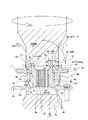
自動車の車輪を懸架装置に対して回転自在に支持する為に、車輪支持用転がり軸受ユニットを使用する。この様な車輪支持用転がり軸受ユニットとして特許文献1、特許文献2には、図8の様な構造が記載されている。この車輪支持用転がり軸受ユニットは、外径側軌道輪部材である外輪1の内径側に、内径側軌道輪部材であるハブ2を、第一列、第二列の両転がり軸受3、4により回転自在に支持している。このうちの外輪1は、内周面の一端(車両への組み付け状態で車両の幅方向外側となる端で、図8の左端。請求項1に記載した一端とは異なる。)側部分に、第一列の転がり軸受3を構成する為の第一の外輪軌道5を、同じく他端(車両への組み付け状態で車両の幅方向中央側となる端で、図8の右端。請求項1に記載した他端とは異なる。)側部分に、第二列の転がり軸受4を構成する為の第二の外輪軌道6を、それぞれ形成すると共に、懸架装置に支持固定する為の取付部7を外周面に設けている。   A wheel supporting rolling bearing unit is used to rotatably support a vehicle wheel with respect to a suspension device. Patent Documents 1 and 2 disclose a structure as shown in FIG. 8 as such a wheel supporting rolling bearing unit. In this wheel supporting rolling bearing unit, a hub 2 as an inner diameter side bearing ring member is provided on the inner diameter side of an outer ring 1 as an outer diameter side bearing ring member by first and second rows of rolling bearings 3 and 4. It is rotatably supported. Of these, the outer ring 1 is located at one end of the inner peripheral surface (the end that is the outer side in the width direction of the vehicle when assembled to the vehicle, the left end in FIG. 8, which is different from the one end described in claim 1). The first outer ring raceway 5 for forming the first row of rolling bearings 3 is also provided with the other end (an end which is the center in the width direction of the vehicle when assembled to the vehicle, the right end in FIG. 8). On the side portions, second outer raceways 6 for forming the second row of rolling bearings 4 are formed, and mounting portions 7 for supporting and fixing to the suspension device are provided. It is provided on the outer peripheral surface.

又、上記ハブ2は、請求項1に記載した軸部材であるハブ本体8と、内輪9とを組み合わせて成る。このうちのハブ本体8は、車輪を支持する為のフランジ10を外周面の一端部に、上記第一列の転がり軸受3を構成する為の第一の内輪軌道11を同じく中間部に、この第一の内輪軌道11を形成した部分よりも小径の段部13を同じく他端部に、それぞれ形成している。尚、上記第一の内輪軌道11は、上記ハブ本体8の中間部に外嵌した別の内輪の外周面に形成する場合もある。又、上記内輪9は、上記第二列の転がり軸受4を構成する為の第二の内輪軌道12を、外周面に有する。この様な内輪9は、上記段部13に圧入外嵌すると共に、上記ハブ本体8の他端部に設けたかしめ部14により、上記段部13の段差面15に向け抑え付けている。この様なかしめ部14は、上記ハブ本体8の他端部で、少なくとも上記段部13に圧入(締り嵌めで)外嵌した内輪9の他端面よりも軸方向に突出する部分に形成した円筒部16を、揺動プレス加工等により直径方向外方に塑性変形させて形成する。   The hub 2 is formed by combining a hub body 8, which is a shaft member described in claim 1, with an inner ring 9. The hub body 8 includes a flange 10 for supporting the wheels at one end of the outer peripheral surface, and a first inner raceway 11 for forming the first row of rolling bearings 3 at an intermediate portion. A step portion 13 having a smaller diameter than the portion where the first inner raceway 11 is formed is similarly formed at the other end. The first inner raceway 11 may be formed on the outer peripheral surface of another inner race fitted to the intermediate portion of the hub main body 8 in some cases. The inner race 9 has a second inner raceway 12 for forming the second row of rolling bearings 4 on its outer peripheral surface. Such an inner ring 9 is press-fitted and externally fitted to the step portion 13 and pressed down toward a step surface 15 of the step portion 13 by a caulking portion 14 provided at the other end of the hub body 8. Such a caulking portion 14 is a cylinder formed at the other end of the hub main body 8 at a portion protruding in the axial direction from at least the other end surface of the inner ring 9 press-fitted (tightly fitted) to the step portion 13 at least. The portion 16 is formed by plastically deforming diametrically outward by rocking press working or the like.

又、上記第一、第二の外輪軌道5、6と上記第一、第二の内輪軌道11、12との間には、それぞれ複数個ずつの転動体17、17を、それぞれ第一、第二の保持器18、19により転動自在に保持した状態で設けている。これにより、上記第一列、第二列の両転がり軸受3、4を構成している。尚、トラック等の重量の嵩む自動車用の車輪支持用転がり軸受ユニットの場合には、上記転動体17、17として図示の様な円すいころを使用するが、乗用車等の比較的重量の軽い自動車用の車輪支持用転がり軸受ユニットの場合には、上記転動体として、後述する図11や本発明の実施例を示す図1、3、6、7の様に、玉を使用する場合が多い。又、図示の例では、上記外輪1の一端部に支持したシールリング20により、上記複数個の転動体17、17を設けた空間21の一端開口部を密閉している。尚、図示は省略するが、この空間21の他端開口部も、別のシールリングにより密閉するか、或は、上記外輪1の他端部に装着したカバーにより塞ぐ。これにより、上記空間21に封入したグリース等の潤滑剤が外部に漏洩するのを防止すると共に、外部からこの空間21内に泥水等の異物が侵入するのを防止する。   Between the first and second outer raceways 5 and 6 and the first and second inner raceways 11 and 12, a plurality of rolling elements 17 and 17 are provided, respectively. It is provided in a state where it is rollably held by two retainers 18 and 19. Thus, the rolling bearings 3 and 4 in the first and second rows are configured. In the case of a wheel supporting rolling bearing unit for a heavy vehicle such as a truck, tapered rollers as shown are used as the rolling elements 17 and 17 for a relatively light vehicle such as a passenger car. In the case of the wheel bearing rolling bearing unit described above, a ball is often used as the rolling element as shown in FIG. 11 to be described later and FIGS. 1, 3, 6, and 7 showing an embodiment of the present invention. In the illustrated example, a seal ring 20 supported at one end of the outer ring 1 seals an opening at one end of a space 21 provided with the plurality of rolling elements 17 and 17. Although not shown, the opening at the other end of the space 21 is also sealed by another seal ring, or closed by a cover attached to the other end of the outer ring 1. This prevents the lubricant such as grease sealed in the space 21 from leaking to the outside, and prevents foreign substances such as muddy water from entering the space 21 from the outside.

上述の様に構成する車輪支持用転がり軸受ユニットを組み立てる際には、先ず、上記ハブ本体8の周囲に上記外輪1を配置すると共に、上記第一の内輪軌道11と上記第一の外輪軌道5との間に上記複数個の転動体17、17を、上記第一の保持器18により保持した状態で設ける。これと共に、上記シールリング20を、上記円筒状の空間21の一端開口部を塞ぐ状態で装着する。尚、ここまでの組立作業の順序は、車輪支持用転がり軸受ユニットの構造によって、多少異なる。   When assembling the rolling bearing unit for supporting a wheel configured as described above, first, the outer ring 1 is arranged around the hub body 8, and the first inner raceway 11 and the first outer raceway 5 are arranged. The plurality of rolling elements 17, 17 are provided in a state held by the first holder 18. At the same time, the seal ring 20 is mounted so as to close one end opening of the cylindrical space 21. The order of the assembling operation so far differs somewhat depending on the structure of the rolling bearing unit for supporting the wheel.

例えば、図8に示した車輪支持用転がり軸受ユニットの場合には、先ず、上記第一の内輪軌道11の周囲に上記複数個の転動体17、17を、上記第一の保持器18に保持した状態で配置する。尚、この状態で、上記第一の内輪軌道11と上記各転動体17、17の転動面とに、グリース等の潤滑剤を塗布しておく。又、上記外輪1の一端部に、上記シールリング20を外嵌固定しておく。図示の例の場合、このシールリング20は、断面L字形で全体を円環状に形成した芯金22と、同じく円環状に形成して、この芯金22の内径側部分に焼き付け、接着等により固定した弾性材23とから成る。上記外輪1の一端部には、このうちの芯金22を外嵌固定する。   For example, in the case of the wheel bearing rolling bearing unit shown in FIG. 8, first, the plurality of rolling elements 17, 17 are held around the first inner raceway 11 by the first cage 18. Place it in a state where it is done. In this state, a lubricant such as grease is applied to the first inner raceway 11 and the rolling surfaces of the rolling elements 17 and 17 in advance. Further, the seal ring 20 is externally fitted and fixed to one end of the outer race 1. In the case of the example shown in the figure, the seal ring 20 is formed in an annular shape with an L-shaped cross section, and is formed in the same annular shape. And a fixed elastic member 23. One end of the outer race 1 is externally fitted with and fixed to the core metal 22.

次いで、この様にシールリング20を外嵌固定した上記外輪1に上記ハブ本体8を、その他端部側から挿通し、この外輪1をハブ本体8の周囲に配置する。この挿通作業により、上記第一の外輪軌道5が上記第一の保持器18により保持した複数個の転動体17、17の転動面と当接する。尚、この外輪1の挿通作業を行なうのに先立ち、上記第一の外輪軌道5にも、グリース等の潤滑剤を塗布しておく。又、上述の様に外輪1をハブ本体8の周囲に配置する事に伴い、上記シールリング20を構成する弾性材23に設けた複数本のシールリップの先端縁が、上記ハブ本体8の一端寄り部外周面及び前記フランジ10の基端部側面に当接(運転時には摺接)し、上記円筒状の空間21の一端開口部を密閉する。   Next, the hub body 8 is inserted from the other end side into the outer ring 1 on which the seal ring 20 is externally fixed as described above, and the outer ring 1 is arranged around the hub body 8. By this insertion work, the first outer raceway 5 comes into contact with the rolling surfaces of the plurality of rolling elements 17, 17 held by the first holder 18. Before the outer ring 1 is inserted, a lubricant such as grease is also applied to the first outer ring track 5. As described above, the outer ring 1 is arranged around the hub body 8, and the leading edges of the plurality of seal lips provided on the elastic member 23 constituting the seal ring 20 are connected to one end of the hub body 8. It comes into contact with the outer peripheral surface of the deviated portion and the side surface of the base end of the flange 10 (slidingly contacts during operation), and seals the opening at one end of the cylindrical space 21.

上述の様にハブ本体8の周囲に外輪1を配置しつつ、上記第一の内輪軌道11と上記第一の外輪軌道5との間に上記第一の保持器18により保持した複数個の転動体17、17を設けると共に、上記シールリング20により前記空間21の一端開口部を塞いだならば、次いで、前記内輪9を上記ハブ本体8の他端部に外嵌する。この外嵌作業に先立って、この内輪9の外周面に形成した第二の内輪軌道12の周囲に複数個の転動体17、17を、前記第二の保持器19により保持した状態で設置しておく。そして、この状態で上記内輪9を、上記ハブ本体8の他端部に形成した段部13に、締り嵌めで外嵌する。この外嵌作業は、図9に示す様に、上記ハブ本体8の一端面を支持台24の上面に載置した状態で、上記内輪9を圧入治具25により上記段部13に押し込む事により行なう。そして、上記外嵌作業に伴って、上記第二の保持器19により保持した複数個の転動体17、17の転動面を、上記外輪1の他端寄り部内周面に形成した第二の外輪軌道6に当接させる。この際、上記外輪1を上記ハブ本体8に対し、回転若しくは往復揺動させて、上記各転動体17、17の転動面と上記各軌道5、6、11、12との当接状態を安定させる。   While the outer ring 1 is arranged around the hub body 8 as described above, the plurality of rollers held by the first retainer 18 between the first inner ring track 11 and the first outer ring track 5 are arranged. When the moving bodies 17 and 17 are provided and the one end opening of the space 21 is closed by the seal ring 20, the inner ring 9 is then fitted to the other end of the hub body 8. Prior to the outer fitting operation, a plurality of rolling elements 17 are set around the second inner raceway 12 formed on the outer peripheral surface of the inner race 9 while being held by the second retainer 19. Keep it. Then, in this state, the inner ring 9 is externally fitted to the step portion 13 formed at the other end of the hub main body 8 by interference fitting. This outer fitting work is performed by pressing the inner ring 9 into the step portion 13 with a press-fitting jig 25 with one end surface of the hub body 8 placed on the upper surface of the support base 24 as shown in FIG. Do. Then, with the outer fitting operation, the rolling surfaces of the plurality of rolling elements 17, 17 held by the second holder 19 are formed on the inner peripheral surface near the other end of the outer ring 1. It is brought into contact with the outer raceway 6. At this time, the outer ring 1 is rotated or reciprocally oscillated with respect to the hub body 8 so that the contact surfaces between the rolling surfaces of the rolling elements 17, 17 and the tracks 5, 6, 11, 12 are adjusted. Stabilize.

次いで、上記ハブ本体8の他端部に形成した円筒部16を直径方向外方に塑性変形させて、かしめ部14を形成する。このかしめ部14の形成作業は、図10に示す様に、上記ハブ本体8の一端面を支持台24の上面に載置した状態で、上記円筒部16を押型26で押圧する事により行なう。この押型26の先端面(図10の下端面)中央部には、上記円筒部16の内側に押し込み自在な円錐台状の凸部27を形成し、この凸部27の周囲に断面円弧状の凹部28を、この凸部27の全周を囲む状態で形成している。この様な形状の凸部27と凹部28とを有する押型26を上記円筒部16の先端部に押し付ければ、この円筒部16の先端部を直径方向外方にかしめ広げ(塑性変形させ)て、上記かしめ部14を形成する事ができる。   Next, the cylindrical portion 16 formed at the other end of the hub main body 8 is plastically deformed radially outward to form the caulked portion 14. As shown in FIG. 10, the forming operation of the caulking portion 14 is performed by pressing the cylindrical portion 16 with a pressing die 26 while the one end surface of the hub body 8 is placed on the upper surface of the support stand 24. At the center of the tip end surface (lower end surface in FIG. 10) of the pressing die 26, a truncated cone-shaped convex portion 27 which can be pushed into the inside of the cylindrical portion 16 is formed. The concave portion 28 is formed so as to surround the entire circumference of the convex portion 27. When the pressing die 26 having the convex portion 27 and the concave portion 28 having such a shape is pressed against the distal end portion of the cylindrical portion 16, the distal end portion of the cylindrical portion 16 is swaged outward in the diametric direction (plastically deformed). The caulking portion 14 can be formed.

上記押型26の中心軸αは、上記ハブ本体8の中心軸βに対し、小さな(例えば1〜10度程度の)角度θだけ傾斜している。上記かしめ部14の加工時に上記押型26は、その中心軸αを上記ハブ本体8の中心軸βの周りで(歳差運動による中心軸の軌跡の如く)振れ回り運動させつつ、上記ハブ本体8に向け押し付けられる。この為、上記押型26から上記円筒部16へは、軸方向に関して一端側に、径方向に関して外方に、それぞれ向いた荷重が加えられ、この様に荷重を加えられる部分が、上記円筒部16の円周方向に関して連続的に変化(押圧部分が公転)する。そして、この様にして得たかしめ部14により上記内輪9の他端面を軸方向に抑え付ける事で、この内輪9を上記ハブ本体8に固定する。この様に上記かしめ部14を形成する際にも、前記外輪1を上記ハブ本体8に対し、回転若しくは往復揺動させて、上記各転動体17、17の転動面と上記各軌道5、6、11、12との当接状態を安定させる。   The center axis α of the pressing die 26 is inclined at a small angle θ (for example, about 1 to 10 degrees) with respect to the center axis β of the hub body 8. When the caulking portion 14 is processed, the pressing die 26 causes the center axis α to oscillate around the center axis β of the hub body 8 (such as the locus of the center axis due to precession), Pressed toward. For this reason, a load is applied from the pressing die 26 to the cylindrical portion 16 at one end in the axial direction and outward in the radial direction, and the portion to which the load is applied is the cylindrical portion 16. Continuously changes in the circumferential direction (the pressed portion revolves). Then, the inner ring 9 is fixed to the hub body 8 by pressing the other end surface of the inner ring 9 in the axial direction by the caulking portion 14 thus obtained. Even when the caulking portion 14 is formed in this way, the outer ring 1 is rotated or reciprocally oscillated with respect to the hub main body 8 so that the rolling surfaces of the rolling elements 17 and 17 and the tracks 5 and The contact state with 6, 11, 12 is stabilized.

上述の様に円筒部16を塑性変形してかしめ部14とする作業を効率良く行ない、良質のかしめ部14を得る為に、上記押型26を凹部28の断面形状を工夫する事が、例えば特許文献3、特許文献4に記載されている様に、従来から考えられている。これら各特許文献3、4に記載された発明は、得られるかしめ部14の外面の断面形状を、途中で曲率半径が変化する複合曲線とするものである。更には、各部の形状及び寸法に関して、上記かしめ部14の加工作業に伴う各部の変形を考慮した上でこのかしめ部14を加工する事も、前記特許文献1の他、特許文献5に記載されている。   In order to efficiently perform the work of forming the caulking portion 14 by plastically deforming the cylindrical portion 16 as described above, and to obtain a good-quality caulking portion 14, it is necessary to devise the cross-sectional shape of the concave portion 28 of the pressing die 26, for example, As described in Document 3 and Patent Document 4, it has been conventionally considered. In the inventions described in Patent Documents 3 and 4, the cross-sectional shape of the obtained outer surface of the caulking portion 14 is a compound curve whose radius of curvature changes in the middle. Further, regarding the shape and dimensions of each part, processing of the caulking part 14 in consideration of the deformation of each part accompanying the processing work of the caulking part 14 is described in Patent Document 5 in addition to Patent Document 1 described above. ing.

但し、以上に述べた特許文献1〜5に記載された従来技術は、何れも押型26の凹部28の断面形状のうち、この押型26の中心軸を含む仮想平面に関する断面形状に関するものである。上記凹部28の円周方向の形状に関しては、特に工夫するものではない。加工時に上記押型26の中心軸αを前記ハブ本体8の中心軸βに対し角度θだけ傾斜させるとは言え、この角度θは1〜10度程度の小さな値であり、上記凹部28のうちで前記円筒部16乃至はかしめ部14に当接する部分の円周方向の形状は、僅かな凸形状とは言え、平坦に近いものである。従って、上記凹部28と上記円筒部16乃至はかしめ部14との当接面積は比較的大きくなり、この円筒部16乃至はかしめ部14は、上記押型26の加圧作業に伴い、比較的広い範囲で塑性変形する。この為、この塑性変形の為に要する荷重、即ち、上記押型26を押圧する為に要する荷重が大きくなって、上記かしめ部14の加工装置が大型化する。   However, the prior arts described in Patent Literatures 1 to 5 described above all relate to the cross-sectional shape of a virtual plane including the central axis of the pressing die 26 among the cross-sectional shapes of the concave portion 28 of the pressing die 26. The circumferential shape of the recess 28 is not particularly devised. Although the center axis α of the pressing die 26 is inclined by an angle θ with respect to the center axis β of the hub body 8 during processing, this angle θ is a small value of about 1 to 10 degrees. The shape in the circumferential direction of the portion that comes into contact with the cylindrical portion 16 to the caulking portion 14 is almost flat, though it is slightly convex. Therefore, the contact area between the concave portion 28 and the cylindrical portion 16 to the caulking portion 14 is relatively large, and the cylindrical portion 16 to the caulking portion 14 are relatively wide due to the pressing operation of the pressing die 26. Plastically deforms in the range. For this reason, the load required for the plastic deformation, that is, the load required for pressing the pressing die 26 becomes large, and the processing apparatus for the caulking portion 14 becomes large.

この荷重を小さくして上記かしめ部14の加工装置の小型化を図る為には、押型と円筒部16若しくはかしめ部14との接触面積を狭くしてこの押型の加圧作業に伴って塑性変形する範囲を狭くし、この押型を押圧する為に要する荷重を小さくする事が考えられる。この為には、この押型のうちで上記円筒部16乃至はかしめ部14に当接する部分の円周方向の形状を、曲率の大きな(曲率半径の小さな)凸形状とする事が考えられる。この点に就いて、図11〜12により説明する。   In order to reduce the load and reduce the size of the processing device for the caulking portion 14, the contact area between the pressing die and the cylindrical portion 16 or the caulking portion 14 is reduced, and plastic deformation is caused by the pressing operation of the pressing die. It is conceivable to narrow the range to be pressed and to reduce the load required to press the pressing die. For this purpose, it is conceivable that the circumferential shape of a portion of the pressing die that comes into contact with the cylindrical portion 16 to the caulking portion 14 is a convex shape having a large curvature (small radius of curvature). This point will be described with reference to FIGS.

図11に示したかしめ部14の加工装置の場合、押型26aの中心軸α´のハブ本体8aの中心軸βに対する傾斜角度θ´を、前述の図10に示した従来構造よりも大きく(例えば20〜40度程度に)している。従って、上記押型26aの下面に形成した凹部28aの円周方向に関する断面形状は、図12に示す様な、曲率の大きな凸円弧である。この様な押型26aを上記大きな傾斜角度θ´で振れ回り運動させつつ上記かしめ部14を加工すれば、円筒部16若しくはかしめ部14と上記凹部28aとの接触面積が狭くなる。この為、上記押型26aを下方に押圧する荷重を特に大きくしなくても、上記かしめ部14の加工を行なえる。又、この荷重を小さく抑える事で、加工時に於けるハブ本体8aや内輪9aの弾性変形を抑えて、良質の車輪支持用転がり軸受ユニットを得られる。   In the case of the processing apparatus of the caulking portion 14 shown in FIG. 11, the inclination angle θ ′ of the center axis α ′ of the pressing die 26a with respect to the center axis β of the hub body 8a is larger than the conventional structure shown in FIG. About 20 to 40 degrees). Accordingly, the cross-sectional shape in the circumferential direction of the concave portion 28a formed on the lower surface of the pressing die 26a is a convex arc having a large curvature as shown in FIG. If the caulking portion 14 is processed while the press die 26a is swung at the large inclination angle θ ', the contact area between the cylindrical portion 16 or the caulking portion 14 and the recess 28a is reduced. Therefore, the caulking portion 14 can be processed without particularly increasing the load for pressing the pressing die 26a downward. Also, by suppressing this load to a small value, the elastic deformation of the hub body 8a and the inner ring 9a during processing can be suppressed, and a good-quality wheel supporting rolling bearing unit can be obtained.

この様に押型の一部で円筒部16及びかしめ部14を加圧する部分の円周方向に関する断面形状を凸円弧にする構造として、前記特許文献2には、図13に示す様な構造が記載されている。この従来構造では、ハブ本体8の一端部(反かしめ側端部で図13の下端部。請求項1に記載した一端とは異なる。)を支持軸受29により回転自在に支持すると共に、外輪1を図示しない抑え治具等により固定して(或いは外輪1は特に固定せず)、内輪9及び上記ハブ本体8が、この外輪1の内側で回転する事を自在とする。そして、このハブ本体8の他端部(かしめ側端部で図13の上端部。請求項1に記載した他端とは異なる。)に設けた円筒部16の先端部の一部に、ロール30の先端寄り部を強く押し付ける。このロール30の先端寄り部外周面には、全周に亙り凹部31を形成している。従って、この状態で、上記内輪9及びハブ本体8と上記ロール30とを、それぞれの中心軸を中心として回転させれば、上記円筒部16の先端部を直径方向外方にかしめ広げて、上記かしめ部14を形成する事ができる。上記凹部31の円周方向に関する曲率は大きいので、この凹部31と上記円筒部16若しくはかしめ部14との接触面積は狭く、上記ロール30の押し付け力を特に大きくしなくても、上記かしめ部14の加工を行なえる。   A structure as shown in FIG. 13 is described in Patent Literature 2 as a structure in which a cross-sectional shape in a circumferential direction of a portion of the pressing die that presses the cylindrical portion 16 and the caulking portion 14 is formed into a convex arc. Have been. In this conventional structure, one end of the hub main body 8 (the lower end in FIG. 13 at the end opposite to the crimping side, which is different from the one described in claim 1) is rotatably supported by the support bearing 29, and the outer ring 1 is supported. Is fixed by a holding jig (not shown) or the like (or the outer ring 1 is not particularly fixed), so that the inner ring 9 and the hub body 8 can freely rotate inside the outer ring 1. A roll is attached to a part of the tip of the cylindrical portion 16 provided at the other end of the hub body 8 (the upper end in FIG. 13 at the caulking side end, which is different from the other end described in claim 1). Press firmly on the tip of 30. A concave portion 31 is formed over the entire periphery of the outer peripheral surface of the roll 30 near the leading end. Therefore, in this state, if the inner ring 9 and the hub body 8 and the roll 30 are rotated about their respective central axes, the distal end of the cylindrical portion 16 is swaged outward in the diameter direction, and The caulking part 14 can be formed. Since the concave portion 31 has a large curvature in the circumferential direction, the contact area between the concave portion 31 and the cylindrical portion 16 or the caulking portion 14 is small, and the caulking portion 14 can be formed without particularly increasing the pressing force of the roll 30. Can be processed.

但し、図11に示す様に押型26aの振れ回り角度θ´を大きくしたり、或は図13に示す様に大きく傾斜したロール30を使用して円筒部16をかしめ部14に加工する場合には、加工装置が発生する押圧力を加工部に有効に伝える事ができず、必ずしも加工装置の小型化を十分に図れない。この理由は、上記押型26a或は上記ロール30の一部で上記円筒部16或はかしめ部14に突き当てられる部分の円周方向に関する曲率が必ずしも大きくならず、しかも、この部分への押圧力の伝達効率があまり良くない為である。   However, when the swivel angle θ ′ of the pressing die 26a is increased as shown in FIG. 11, or when the cylindrical portion 16 is processed into the caulking portion 14 using the roll 30 which is greatly inclined as shown in FIG. Cannot effectively transmit the pressing force generated by the processing apparatus to the processing section, and the size of the processing apparatus cannot always be sufficiently reduced. The reason is that the curvature in the circumferential direction of the portion of the pressing die 26a or a part of the roll 30 which is abutted against the cylindrical portion 16 or the caulking portion 14 is not always large, and the pressing force on this portion is not necessarily increased. This is because the transmission efficiency is not so good.

即ち、大きな傾斜角度で設置された押型26a或はロール30の先端部を上記円筒部16或はかしめ部14に強く突き当ててこのかしめ部14の加工を行なう為には、上記押型26a或はロール30の曲げ剛性を十分に確保しなければならない。従って、これら押型26a或はロール30の直径をあまり小さくはできず、上記突き当てられる部分の円周方向に関する曲率を大きくするには限度がある。又、上記押型26a或はロール30の先端部を上記円筒部16或はかしめ部14に押し付ける為の力は、加工装置に設けた油圧シリンダ等で上記押型26a或はロール30を、上記円筒部16或はかしめ部14に向け、下方に押圧する事で発生させる。この場合に、傾斜した状態で配置され、しかも先端を自由端として片持ち式に支持された、上記押型26a或はロール30の先端部から上記円筒部16或はかしめ部14に、上記油圧シリンダ等で発生した押圧力を効率良く伝達できない。この結果、この油圧シリンダの小型化を図りにくい。   That is, in order to press the tip of the pressing die 26a or the roll 30 installed at a large inclination angle against the cylindrical portion 16 or the caulking portion 14 to process the caulking portion 14, the pressing die 26a or The bending rigidity of the roll 30 must be sufficiently ensured. Therefore, the diameter of the pressing die 26a or the roll 30 cannot be made very small, and there is a limit to increasing the curvature in the circumferential direction of the abutted portion. The force for pressing the tip of the pressing die 26a or the roll 30 against the cylindrical portion 16 or the caulking portion 14 is determined by pressing the pressing die 26a or the roll 30 with a hydraulic cylinder or the like provided in a processing device. It is generated by pressing downward toward the crimping portion 16 or the caulking portion 14. In this case, the hydraulic cylinder is disposed from the leading end of the pressing die 26a or the roll 30 to the cylindrical portion 16 or the caulking portion 14, which is disposed in an inclined state and is supported in a cantilever manner with the leading end being a free end. Etc. cannot be transmitted efficiently. As a result, it is difficult to reduce the size of the hydraulic cylinder.

特開2000−289403号公報JP 2000-289403 A 特開2000−343905号公報JP 2000-343905 A 米国特許第6113279号明細書U.S. Pat. No. 6,113,279 特開2000−87978号公報JP 2000-87978 A 特開2002−206536号公報JP-A-2002-206536

本発明は、上述の様な事情に鑑みて、製造装置の小型化、低廉化を図れるだけでなく、良質の車輪支持用転がり軸受ユニットを安定して造れる車輪支持用転がり軸受ユニットの製造方法及び製造装置を実現すべく発明したものである。   In view of the circumstances as described above, the present invention not only can reduce the size and cost of the manufacturing apparatus, but also can stably produce a good-quality wheel supporting rolling bearing unit. It has been invented to realize a manufacturing apparatus.

本発明の車輪支持用転がり軸受ユニットの製造方法及び製造装置の対象となる車輪支持用転がり軸受ユニットは、内周面に第一、第二の外輪軌道を有する外径側軌道輪部材と、外周面に第一、第二の内輪軌道を有する内径側軌道輪部材と、これら第一、第二の内輪軌道と上記第一、第二の外輪軌道との間にそれぞれ複数個ずつ転動自在に設けられた転動体とを備える。
このうちの内径側軌道輪部材は、その中間部外周面に直接又は別体の内輪を介して上記第一の内輪軌道を設けた軸部材と、その外周面に上記第二の内輪軌道を設けた内輪とから成る。そして、この内輪は、上記軸部材の一端部に外嵌し、更にこの軸部材の一端部に設けた円筒部を直径方向外方に塑性変形させる事で形成したかしめ部によりその軸方向一端面を抑え付けられる事で、上記軸部材に対し支持固定されている。
A wheel supporting rolling bearing unit to be manufactured and manufactured by the method and apparatus for manufacturing a wheel supporting rolling bearing unit of the present invention includes an outer diameter side bearing ring member having first and second outer ring raceways on an inner circumferential surface, and an outer circumferential surface. The inner and outer raceway ring members having first and second inner raceways on the surface, and each of the first and second inner raceways and the first and second outer raceways can roll freely by a plurality of each. And a rolling element provided.
Of these, the inner raceway ring member is provided with the shaft member provided with the first inner raceway directly or via a separate inner race on the outer peripheral surface of the intermediate portion, and the second inner raceway on the outer peripheral surface thereof. And an inner ring. The inner ring is fitted to one end of the shaft member, and furthermore, a cylindrical portion provided at one end of the shaft member is plastically deformed diametrically outward by a caulking portion formed at one end surface in the axial direction. Is supported and fixed to the shaft member.

又、請求項1に記載した車輪支持用転がり軸受ユニットの製造方法は、上述した様な車輪支持用転がり軸受ユニットを造る為、加圧部材により上記円筒部の円周方向の一部に、軸方向に関して他端側に、径方向に関して外方に、それぞれ向いた荷重を加える。そして、この荷重を加える部分を上記円筒部の円周方向に関して連続的に変化させる事により、この円筒部を徐々に塑性変形させて、上記かしめ部とする。
特に、請求項1に記載した車輪支持用転がり軸受ユニットの製造方法に於いては、上記加圧部材が加圧ローラであり、この加圧ローラの中心軸を含む仮想平面に関するこの加圧ローラの外周面の断面形状が、上記かしめ部の外面の断面形状に見合う(同じ母線で凹凸が逆の)形状である。そして、上記加圧ローラをその中心軸を自転軸として自転させつつ上記軸部材の中心軸の周囲を公転させながら上記加圧ローラをこの軸部材に向け押し付けて、上記円筒部を塑性変形させる。
Further, in the method for manufacturing a wheel supporting rolling bearing unit according to claim 1, in order to manufacture the wheel supporting rolling bearing unit as described above, a pressure member applies a shaft to a part of the cylindrical portion in a circumferential direction. A load is applied to the other end in the direction and outward in the radial direction. Then, by continuously changing the portion to which the load is applied in the circumferential direction of the cylindrical portion, the cylindrical portion is gradually plastically deformed to form the caulked portion.
In particular, in the method of manufacturing a rolling bearing unit for supporting a wheel according to claim 1, the pressing member is a pressing roller, and the pressing roller is formed on a virtual plane including a center axis of the pressing roller. The cross-sectional shape of the outer peripheral surface is a shape that matches the cross-sectional shape of the outer surface of the caulked portion (the same generatrix and the concavities and convexities are reversed). Then, the pressure roller is pressed against the shaft member while revolving around the central axis of the shaft member while revolving around the central axis of the shaft member while rotating the pressure roller around the center axis thereof, thereby plastically deforming the cylindrical portion.

又、請求項11に記載した車輪支持用転がり軸受ユニットの製造装置は、支持台と、加圧ヘッドと、少なくとも1個の加圧ローラとを備える。
このうちの支持台は、上記内径側軌道輪部材の他端部を支えるものである。
又、上記加圧ヘッドは、上記支持台の上方に、昇降及び回転自在に設けられたものである。
又、上記加圧ローラは、上記加圧ヘッドの下端部で上記内径側軌道輪部材の円筒部に対向する部分に、この内径側軌道輪部材の直径方向に配置された枢軸を中心とする自転自在に、両持ち式に支持されている。
An apparatus for manufacturing a rolling bearing unit for supporting a wheel according to an eleventh aspect includes a support base, a pressing head, and at least one pressing roller.
The support stand supports the other end of the inner race member.
The pressure head is provided above and below the support table so as to be able to move up and down and rotate freely.
The pressure roller has a lower end portion of the pressure head and a portion which faces a cylindrical portion of the inner race member, and which rotates around a pivot disposed in the diameter direction of the inner race member. It is freely supported by both sides.

上述の様に構成する本発明の車輪支持用転がり軸受ユニットの製造方法及び製造装置の場合には、軸部材の一端部に設けた円筒部若しくはこの円筒部が塑性変形したかしめ部を押圧する加圧ローラの、円周方向に関する曲率を大きく(曲率半径を小さく)できる。従って、上記円筒部若しくはかしめ部と上記加圧ローラとの接触面積を狭くして、この円筒部若しくはかしめ部を、局所的に塑性変形させる事ができる。この為、加圧ヘッドを押圧する為の力を小さくできて、製造装置の小型化を図ると共に、製造時に於ける軸部材や内輪の弾性変形を抑えて、良質の車輪支持用転がり軸受ユニットを得られる。更に、加圧ヘッドを上記円筒部若しくはかしめ部に向け押圧する、油圧シリンダ等の押圧手段が発生する力を、上記加圧ヘッド及び上記加圧ローラに向け効率良く伝達できる。この為、製造装置の小型化をより有効に図れる。
この様に本発明の車輪支持用転がり軸受ユニットの製造方法及び製造装置によれば、製造装置の小型化、低廉化を図れるだけでなく、良質の車輪支持用転がり軸受ユニットを安定して造れる。
In the case of the manufacturing method and the manufacturing apparatus of the wheel supporting rolling bearing unit of the present invention configured as described above, the cylindrical portion provided at one end of the shaft member or the caulking portion which presses the caulked portion in which the cylindrical portion is plastically deformed. The curvature of the pressure roller in the circumferential direction can be increased (the radius of curvature can be reduced). Therefore, the contact area between the cylindrical portion or the caulked portion and the pressure roller can be reduced, and the cylindrical portion or the caulked portion can be locally plastically deformed. For this reason, the force for pressing the pressure head can be reduced, and the manufacturing apparatus can be reduced in size.Also, the elastic deformation of the shaft member and the inner ring during manufacturing can be suppressed, and a good quality rolling bearing unit for wheel support can be obtained. can get. Further, a force generated by a pressing means such as a hydraulic cylinder for pressing the pressing head toward the cylindrical portion or the caulking portion can be efficiently transmitted to the pressing head and the pressing roller. Therefore, the size of the manufacturing apparatus can be reduced more effectively.
As described above, according to the method and apparatus for manufacturing the wheel supporting rolling bearing unit of the present invention, not only can the manufacturing apparatus be reduced in size and cost, but also a high-quality wheel supporting rolling bearing unit can be stably manufactured.

請求項1に記載した車輪支持用転がり軸受ユニットの製造方法の発明を実施する場合に好ましくは、請求項2に記載した様に、加圧ローラの自転軸の延長線を、軸部材の中心線の延長線と直交させる。
この様に構成すれば、上記加圧ローラを軸部材の一端部に設けた円筒部に向けて強く押し付け易く、かしめ部の加工を能率良く行なえる。
Preferably, when the invention of the method for manufacturing a rolling bearing unit for supporting a wheel described in claim 1 is carried out, the extension line of the rotation shaft of the pressure roller is set to the center line of the shaft member. Perpendicular to the extension of.
According to this structure, the pressure roller is easily pressed strongly against the cylindrical portion provided at one end of the shaft member, and the caulking portion can be efficiently processed.

又、好ましくは、請求項3に記載した様に、上記加圧ローラを軸部材の中心軸の周囲に複数個、円周方向に関して等間隔に配置する。そして、これら複数個の加圧ローラをこの中心軸の周りで互いに同期させて公転させつつ自転させる事により、円筒部を円周方向複数個所で同時に塑性変形させる。
この様に構成すれば、上記各加圧ローラを支持した加圧ヘッド等の支持部材に加わるアキシアル荷重を円周方向に関し均等にして、この支持部材に径方向乃至は曲げ方向の力が加わらない様にできる。そして、この支持部材を押圧する部分の構造を簡単にできる他、この支持部材の耐久性向上も図れる。更に、上記円筒部の加工を円周方向複数個所で同時に行なう為、この円筒部をかしめ部に加工する加工作業の能率化を図れる。又、軸部材に無用な変形が生じる事も抑えて、良質の車輪支持用転がり軸受ユニットを得られる。
Preferably, a plurality of the pressure rollers are arranged around the central axis of the shaft member at equal intervals in the circumferential direction. Then, the plurality of pressure rollers are revolved and rotated around the central axis in synchronization with each other, thereby simultaneously plastically deforming the cylindrical portion at a plurality of positions in the circumferential direction.
With this configuration, the axial load applied to the support member such as the pressure head supporting each of the pressure rollers is made uniform in the circumferential direction, so that no radial or bending force is applied to this support member. I can do it. And the structure of the part which presses this support member can be simplified and the durability of this support member can be improved. Further, since the processing of the cylindrical portion is performed simultaneously at a plurality of positions in the circumferential direction, the efficiency of the processing operation for processing the cylindrical portion into the caulked portion can be improved. In addition, unnecessary deformation of the shaft member is suppressed, and a high-quality wheel supporting rolling bearing unit can be obtained.

又、好ましくは、請求項4に記載した様に、上記円筒部を冷却流体により冷却しつつ塑性変形させる。
この様に構成すれば、上記円筒部をかしめ部に加工する、かしめ加工部の温度上昇を抑えて、上記加圧ローラの寿命を向上させる事ができる。
Preferably, the cylindrical portion is plastically deformed while being cooled by a cooling fluid.
According to this structure, the cylindrical portion is processed into a caulked portion. The temperature rise of the caulked portion can be suppressed, and the life of the pressure roller can be improved.

又、好ましくは、請求項5に記載した様に、上記加圧ローラと上記円筒部との接触により生じてこの円筒部に付着する摩耗粉を除去しつつ、この円筒部を塑性変形させたり、或は、請求項6に記載した様に、上記加圧ローラと上記円筒部との接触により生じてこの加圧ローラに付着する摩耗粉を除去しつつ、この円筒部を塑性変形させる。又は、請求項7に記載した様に、加圧ローラと円筒部との接触により生じてこの加圧ローラに付着する摩耗粉を、この円筒部を塑性変形させる加工工程の前又は後に除去する。
この様に構成すれば、この摩耗粉がこの円筒部と上記加圧ローラとの押し付け面同士の間に噛み込まれる事を防止して、この加圧ローラの寿命を向上させ、且つ、上記円筒部を塑性変形させる事により得られるかしめ部の品質を良好にして、車輪支持用転がり軸受ユニットの歩留を向上させる事ができる。
Preferably, as described in claim 5, the cylindrical portion is plastically deformed while removing abrasion powder generated by contact between the pressure roller and the cylindrical portion and adhered to the cylindrical portion, Alternatively, as described in claim 6, the cylindrical portion is plastically deformed while removing wear powder generated by the contact between the pressure roller and the cylindrical portion and adhering to the pressure roller. Alternatively, as described in claim 7, abrasion powder generated by the contact between the pressure roller and the cylindrical portion and adhered to the pressure roller is removed before or after a processing step of plastically deforming the cylindrical portion.
According to this structure, the wear powder is prevented from being caught between the pressing surfaces of the cylindrical portion and the pressing roller, so that the life of the pressing roller is improved, and The quality of the swaged portion obtained by plastically deforming the portion can be improved, and the yield of the wheel supporting rolling bearing unit can be improved.

又、好ましくは、請求項8に記載した様に、上記加圧ローラの公転速度及び自転速度を、円筒部をかしめ部にまで塑性変形する途中で変化させる。
この様に構成すれば、上記かしめ部の加工を、車輪支持用転がり軸受ユニットの歩留を確保しつつ、能率良く行なえる。
Preferably, the revolution speed and the rotation speed of the pressure roller are changed during the plastic deformation of the cylindrical portion to the caulking portion.
According to this structure, the processing of the caulked portion can be efficiently performed while securing the yield of the wheel supporting rolling bearing unit.

一方、請求項11に記載した車輪支持用転がり軸受ユニットの製造装置の発明を実施する場合に好ましくは、請求項12に記載した様に、加圧ヘッドを、支持台上に載置された内径側軌道輪部材と同心の中心軸を中心とする回転自在とする。そして、加圧ローラを、上記加圧ヘッドの下端部でこの加圧ヘッドの中心よりも外径に寄った部分に設ける。
この様に構成すれば、上記加圧ローラを、軸部材の一端部に設けた円筒部に向け能率良く押し付け、更にこの円筒部のかしめ加工を能率良く行なえる。
On the other hand, when the invention of the manufacturing apparatus of the rolling bearing unit for supporting a wheel described in claim 11 is carried out, preferably, as described in claim 12, the pressure head is provided with an inner diameter mounted on a support base. It is rotatable around a central axis concentric with the side bearing ring member. A pressure roller is provided at a lower end of the pressure head at a portion closer to the outer diameter than the center of the pressure head.
With this configuration, the pressure roller can be efficiently pressed against the cylindrical portion provided at one end of the shaft member, and the cylindrical portion can be efficiently caulked.

又、好ましくは、請求項13に記載した様に、上記加圧ローラの軸方向両端を、上記加圧ヘッドの下端部に回転自在に支持する。
この様に構成すれば、上記加圧ローラの支持剛性を十分に確保して、この加圧ローラを上記軸部材の一端部に設けた円筒部に対し、強く、しかも安定して押し付けられる。
Preferably, both ends in the axial direction of the pressure roller are rotatably supported by the lower end of the pressure head.
With this configuration, the support rigidity of the pressure roller is sufficiently ensured, and the pressure roller is strongly and stably pressed against the cylindrical portion provided at one end of the shaft member.

更に好ましくは、請求項14に記載した様に、上記加圧ローラの外周面と上記円筒部の先端部とが当接する瞬間に加圧ヘッドに加わる衝撃を吸収する衝撃吸収手段を備える。
この様に構成すれば、加圧ローラを支持したラジアル軸受等、車輪支持用転がり軸受ユニットの製造装置の構成各部に過大な衝撃が加わるのを防止して、この車輪支持用転がり軸受ユニットの製造装置の耐久性向上を図れる。
More preferably, there is provided an impact absorbing means for absorbing an impact applied to the pressure head at the moment when the outer peripheral surface of the pressure roller and the tip of the cylindrical portion come into contact with each other.
With this configuration, it is possible to prevent an excessive impact from being applied to each component of the manufacturing device of the rolling bearing unit for supporting the wheel, such as a radial bearing supporting the pressure roller, and to manufacture the rolling bearing unit for supporting the wheel. The durability of the device can be improved.

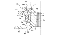
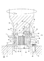
図1〜2は、本発明の実施例1を示している。尚、本実施例は、駆動輪用の車輪支持用転がり軸受ユニットの一端(図1の上端)部にかしめ部14を形成する場合に就いて示している。従って本実施例の場合には、軸部材であるハブ本体8aの中心部にスプライン孔32を形成している。又、上記車輪支持用転がり軸受ユニットの第一列、第二列の転がり軸受3a、4aは、互いに背面組み合わせ型で組み合わされたアンギュラ型の玉軸受としている。この為に本実施例の場合には、外輪1aの内周面に設けた第一、第二の外輪軌道5a、6a、上記ハブ本体8a及び内輪9aの外周面に形成した第一、第二の内輪軌道11a、12aの断面形状を円弧形とすると共に、各転動体17a、17aとして玉を使用している。   1 and 2 show a first embodiment of the present invention. This embodiment shows a case where a caulking portion 14 is formed at one end (upper end in FIG. 1) of a wheel supporting rolling bearing unit for driving wheels. Therefore, in the case of the present embodiment, the spline hole 32 is formed in the center of the hub body 8a as the shaft member. The first and second rows of rolling bearings 3a, 4a of the wheel supporting rolling bearing unit are angular ball bearings combined in a back-to-back combination. For this reason, in the case of the present embodiment, the first and second outer raceways 5a and 6a provided on the inner peripheral surface of the outer race 1a, the first and second outer raceways formed on the outer peripheral surfaces of the hub body 8a and the inner race 9a. The cross-sectional shapes of the inner raceways 11a, 12a are arc-shaped, and balls are used as the rolling elements 17a, 17a.

この様な車輪支持用転がり軸受の一端部に上記かしめ部14を形成する為の、本実施例の製造装置は、支持台33と、加圧ヘッド34と、加圧ローラ35とを備える。
このうちの支持台33は、内径側軌道輪部材である、上記ハブ本体8aと上記内輪9aとを組み合わせたハブ2aの他端部(図1の下端部)を支えるものである。即ち、上記支持台33の上面に、ホイールの中心孔を外嵌する為に上記ハブ8aの他端部に形成した位置決め筒部36の先端縁を突き当て自在としている。この様に位置決め筒部36の先端縁を上記支持台33の上面に突き当てた状態で、上記ハブ2aの中心軸が鉛直方向に位置する。
The manufacturing apparatus according to the present embodiment for forming the caulking portion 14 at one end of such a wheel supporting rolling bearing includes a support base 33, a pressure head 34, and a pressure roller 35.
The support table 33 supports the other end (lower end in FIG. 1) of the hub 2a, which is the inner raceway member, which is a combination of the hub body 8a and the inner ring 9a. That is, the front end edge of the positioning cylinder 36 formed at the other end of the hub 8a is fitted to the upper surface of the support base 33 so as to fit the center hole of the wheel. In this manner, the center axis of the hub 2a is positioned in the vertical direction with the leading edge of the positioning cylinder 36 abutting on the upper surface of the support base 33.

又、上記加圧ヘッド34は、上記支持台33の上方に、図示しない油圧シリンダ等の押圧手段により、昇降自在に設けられている。又、上記加圧ヘッド34の中心軸は、上記支持台33の上面に載置された上記ハブ2aの中心軸と一致する。そして、上記加圧ヘッド34は、自身の中心軸をその中心として回転自在とされている。この加圧ヘッド34の昇降速度と回転速度とは、何れも調節自在である。又、この加圧ヘッド34の下面外径寄り部分には凹部37を、全周に亙って設けている。この凹部37は、上記加圧ヘッド34の下降時に、この加圧ヘッド34の下端部と上記かしめ部14及び内輪9aとの干渉を防止する為のものである。   The pressure head 34 is provided above the support table 33 so as to be able to move up and down by pressing means such as a hydraulic cylinder (not shown). The central axis of the pressure head 34 coincides with the central axis of the hub 2a mounted on the upper surface of the support base 33. The pressure head 34 is rotatable about its own central axis. Both the elevating speed and the rotating speed of the pressure head 34 are adjustable. A concave portion 37 is provided over the entire circumference in a portion of the pressure head 34 near the outer diameter of the lower surface. The recess 37 is for preventing interference between the lower end of the pressure head 34 and the caulking portion 14 and the inner ring 9a when the pressure head 34 is lowered.

この様な凹部37の一部は、残部よりも径方向(図1の左右方向)に関する幅寸法及び軸方向(図1の上下方向)に関する深さ寸法を大きくして、ローラ保持部38としている。そして、このローラ保持部38内に前記加圧ローラ35を、回転自在に保持している。この加圧ローラ35は、上記ハブ2aの一端部に設けた円筒部16に対向する部分に、このハブ2a及び上記加圧ヘッド34の直径方向に配置された枢軸39、39を中心とする自転自在に、 両持ち式に支持されている。   A part of such a concave portion 37 is made a roller holding portion 38 by making the width dimension in the radial direction (left-right direction in FIG. 1) and the depth dimension in the axial direction (vertical direction in FIG. 1) larger than the remaining portion. . The pressure roller 35 is rotatably held in the roller holding portion 38. The pressure roller 35 rotates on a portion facing the cylindrical portion 16 provided at one end of the hub 2a, around pivots 39, 39 arranged in a diametrical direction of the hub 2a and the pressure head 34. It is freely supported and supported by both sides.

即ち、上記加圧ローラ35は、軸方向(図1の左右方向)中間部を、上記円筒部16を塑性変形させて上記かしめ部14に加工する為の加工部40とすると共に、この加工部40の軸方向両端面に上記1対の枢軸39、39を、互いに同心に突設している。上記加工部40の外周面には凹部41を、全周に亙って形成している。上記加圧ローラ35の中心軸を含む仮想平面に関する、上記凹部41の断面形状(母線形状)は、完成後のかしめ部14の外面の断面形状(母線形状)に一致させている。具体的には、上記加工部40の外径を、上記加圧ヘッド34の中心寄りで大きく、外径寄りで小さくしている。そして、これら中心寄りと外径寄りとの間に設ける上記凹部41の母線形状を、異なる曲率半径を有する複数の円弧を滑らかに連続させた複合曲線としている。本実施例の場合には上記母線形状を、前述の特許文献3に記載した様に、上記かしめ部14の内径寄り部分で曲率半径を大きく、先端縁(外周縁)に向かう程曲率半径が小さくなる複合曲線としている。   That is, the pressure roller 35 has a middle part in the axial direction (the left-right direction in FIG. 1) as a processing part 40 for processing the cylindrical part 16 into the caulking part 14 by plastically deforming the cylindrical part 16. The pair of pivots 39, 39 are protruded concentrically from each other on both end surfaces in the axial direction of 40. A concave portion 41 is formed on the outer peripheral surface of the processing portion 40 over the entire circumference. The cross-sectional shape (general bus shape) of the concave portion 41 with respect to the virtual plane including the central axis of the pressure roller 35 matches the cross-sectional shape (general bus shape) of the outer surface of the caulked portion 14 after completion. Specifically, the outer diameter of the processing section 40 is larger near the center of the pressure head 34 and smaller near the outer diameter. The generatrix of the concave portion 41 provided between the center and the outer diameter is a compound curve in which a plurality of arcs having different radii of curvature are smoothly connected. In the case of the present embodiment, as described in Patent Document 3 described above, the radius of curvature is large at the portion of the caulking portion 14 near the inner diameter, and the radius of curvature decreases toward the leading edge (outer peripheral edge). Is a composite curve.

軸方向中間部に上述の様な加工部40を形成した、上記加圧ローラ35は、軸方向両端部に設けた上記1対の枢軸39、39を上記加圧ヘッド34に対し、滑り軸受、ニードル軸受等のラジアル軸受42、42により、両持ち式に、回転自在に支持している。或いは、上記加圧ローラ35に中心孔を形成し、この中心孔に枢軸を挿通して、これら中心孔の内周面と枢軸の中間部外周面との間にニードル軸受、滑り軸受等のラジアル軸受を設けて、上記加圧ローラ35を回転自在に支持しても良い。この場合には、上記枢軸の両端を、上記加圧ヘッド34に支持固定する。何れにしても、この加圧ヘッド34に支持した状態で上記加圧ローラ35の中心軸は、上記加圧ヘッド34及び上記ハブ2aの放射方向に存在する。又、上記加工部40の外周面に形成した凹部41は、このハブ2aの一端部に設けた上記円筒部16若しくは上記かしめ部14に対向する。   The pressure roller 35 having the above-described processing portion 40 formed at the axial middle portion, the pair of pivots 39, 39 provided at both ends in the axial direction are provided with a sliding bearing with respect to the pressure head 34. It is rotatably supported in a double-supported manner by radial bearings 42 and 42 such as needle bearings. Alternatively, a center hole is formed in the pressure roller 35, a pivot is inserted through the center hole, and a radial bearing such as a needle bearing or a slide bearing is provided between an inner peripheral surface of the center hole and an outer peripheral surface of an intermediate portion of the pivot. A bearing may be provided to rotatably support the pressure roller 35. In this case, both ends of the pivot are supported and fixed to the pressure head 34. In any case, the center axis of the pressure roller 35 in the state of being supported by the pressure head 34 exists in the radial direction of the pressure head 34 and the hub 2a. A concave portion 41 formed on the outer peripheral surface of the processing portion 40 faces the cylindrical portion 16 or the caulking portion 14 provided at one end of the hub 2a.

上述の様に構成する本発明の車輪支持用転がり軸受ユニットの製造装置により、ハブ2aの一端部に設けた上記円筒部16を塑性変形させて上記かしめ部14とする作業は、次の様に行なう。先ず、上記加圧ヘッド34を上方に退避させた状態で、前記支持台33の上面に上記ハブ2aを含む車輪支持用転がり軸受ユニットを、上記円筒部16を上にして載置する。次いで、前記押圧手段により上記加圧ヘッド34を下降させて、この加圧ヘッド34の下端部に支持した上記加圧ローラ35の凹部41を、上記円筒部16の先端縁に当接させる。尚、この凹部41と円筒部16の先端縁とが当接した瞬間に上記加圧ローラ35を支持したラジアル軸受42、42等に過大な衝撃が加わるのを防止する為、衝撃吸収手段をを設ける事もできる。この様な衝撃吸収手段としては、上記支持台33と上記加圧ヘッド34との一方又は双方を弾性的に支持するばね等が採用可能である。   The operation of plastically deforming the cylindrical portion 16 provided at one end of the hub 2a to form the caulking portion 14 by the manufacturing apparatus of the wheel supporting rolling bearing unit of the present invention configured as described above is as follows. Do. First, with the pressure head 34 retracted upward, a wheel supporting rolling bearing unit including the hub 2a is placed on the upper surface of the support base 33 with the cylindrical portion 16 facing upward. Next, the pressurizing head 34 is lowered by the pressing means, and the concave portion 41 of the pressurizing roller 35 supported on the lower end of the pressurizing head 34 is brought into contact with the leading edge of the cylindrical portion 16. In order to prevent an excessive impact from being applied to the radial bearings 42, 42 supporting the pressure roller 35 at the moment when the concave portion 41 and the leading edge of the cylindrical portion 16 contact each other, a shock absorbing means is provided. It can also be provided. As such a shock absorbing means, a spring or the like for elastically supporting one or both of the support table 33 and the pressure head 34 can be adopted.

上記凹部41を上記円筒部16の先端縁に当接させたならば、上記加圧ヘッド34を下方に押圧しつつ回転させる。上記円筒部16が未だ変形していない状態では、上記凹部41のうちで上記加圧ヘッド34の中心寄り部分が、上記円筒部16の先端面内周縁に当接する。そして、この状態で上記加圧ヘッド34を下方に押圧すると、上記円筒部16には、軸方向に関して下側(他端側)に、径方向に関して外方に、それぞれ向いた荷重が加わる。又、上記凹部41は曲率の大きな(曲率半径の小さな)凸曲面である為、この凹部41と上記円筒部16との接触面積は極く狭くなる。従って、上記凹部41を上記円筒部16の先端縁に当接させた状態のまま、上記加圧ヘッド34を下方に押圧しつつ回転させれば、上記円筒部16に、径方向外方及び軸方向他端側に向いた局部的な変形が生じる。そして、上記加圧ヘッド34の回転に伴ってこの変形が上記円筒部16全体に拡がり、この円筒部16が前記かしめ部14に加工される。   When the concave portion 41 is brought into contact with the leading edge of the cylindrical portion 16, the pressure head 34 is rotated while being pressed downward. In a state where the cylindrical portion 16 is not yet deformed, a portion of the concave portion 41 near the center of the pressure head 34 abuts on the inner peripheral edge of the distal end surface of the cylindrical portion 16. Then, when the pressing head 34 is pressed downward in this state, a load is applied to the cylindrical portion 16 downward (the other end) in the axial direction and outward in the radial direction. Since the concave portion 41 is a convex curved surface having a large curvature (small radius of curvature), the contact area between the concave portion 41 and the cylindrical portion 16 is extremely small. Therefore, if the pressing head 34 is rotated while pressing downward while keeping the concave portion 41 in contact with the distal end edge of the cylindrical portion 16, the cylindrical portion 16 is moved radially outward and axially. Local deformation occurs toward the other end in the direction. Then, with the rotation of the pressure head 34, this deformation spreads over the entire cylindrical portion 16, and the cylindrical portion 16 is processed into the caulked portion 14.

本実施例の場合、この円筒部16の先端部に突き当たってこの円筒部16を塑性変形させる事により上記かしめ部14とする、上記加圧ローラ35の凹部41の、円周方向に関する曲率が大きい。この為、上記円筒部16若しくはかしめ部14と上記加圧ローラ35との接触面積を狭く(接触状態を点接触乃至は線接触に近い状態)として、この円筒部16若しくはかしめ部14を、局所的に塑性変形させる事ができる。この為、上記加圧ヘッド34を押圧する為の力が小さくて済み、前記油圧シリンダの小型化により製造装置の小型化を図れる。又、製造時に上記円筒部16乃至はかしめ部14を通じて前記ハブ2aに加えられる荷重を低く抑えて、このハブ2aを構成する前記ハブ本体8aや内輪9aの弾性変形を抑え、良質の車輪支持用転がり軸受ユニットを得られる。   In the case of this embodiment, the curvature in the circumferential direction of the concave portion 41 of the pressure roller 35, which is brought into contact with the tip of the cylindrical portion 16 and plastically deforms the cylindrical portion 16 to form the caulking portion 14, is provided. . Therefore, the contact area between the cylindrical portion 16 or the caulking portion 14 and the pressure roller 35 is reduced (the contact state is close to a point contact or a line contact), and the cylindrical portion 16 or the caulking portion 14 is localized. It can be plastically deformed. Therefore, a small force is required to press the pressure head 34, and the manufacturing apparatus can be downsized by downsizing the hydraulic cylinder. Further, the load applied to the hub 2a through the cylindrical portion 16 to the caulking portion 14 during manufacturing is suppressed to be low, and the elastic deformation of the hub body 8a and the inner ring 9a constituting the hub 2a is suppressed. A rolling bearing unit is obtained.

更に本実施例の場合には、上記ハブ2aの中心軸と上記加圧ヘッド34の中心軸とを一致させている。従って、この加圧ヘッド34を上記円筒部16若しくはかしめ部14に向け押圧する、油圧シリンダ等の押圧手段が発生する力を、上記加圧ヘッド34及び上記加圧ローラ35に向け効率良く伝達できる。この為、上記押圧手段のより一層の小型化が可能になり、製造装置の小型化をより有効に図れる。   Further, in the case of the present embodiment, the center axis of the hub 2a and the center axis of the pressure head 34 are aligned. Therefore, a force generated by a pressing means such as a hydraulic cylinder for pressing the pressing head 34 toward the cylindrical portion 16 or the caulking portion 14 can be efficiently transmitted to the pressing head 34 and the pressing roller 35. . For this reason, the size of the pressing means can be further reduced, and the size of the manufacturing apparatus can be reduced more effectively.

尚、図示の例では、加圧ローラ35は加圧ヘッド34の先端部に1個だけ装着しているが、複数個設ける事も可能である。この場合には、複数個の加圧ローラ35を加圧ヘッド34の先端部に、この加圧ヘッド34の回転方向に関して等間隔に配置する。この様に加圧ローラ35を複数個設けた場合には、上記加圧ヘッド34を押圧する押圧手段の出力を大きくする必要があるが、上記円筒部16を上記かしめ部14に加工する作業の能率が向上する。   In the illustrated example, only one pressure roller 35 is attached to the tip of the pressure head 34, but a plurality of pressure rollers 35 may be provided. In this case, a plurality of pressure rollers 35 are arranged at the tip of the pressure head 34 at equal intervals in the rotation direction of the pressure head 34. In the case where a plurality of pressure rollers 35 are provided in this manner, it is necessary to increase the output of the pressing means for pressing the pressure head 34, but the work of processing the cylindrical portion 16 into the caulking portion 14 is required. Efficiency is improved.

又、得られた車輪支持用転がり軸受ユニットの形状及び寸法精度も良好になる。即ち、前述の図13に示した様な、ロール30を使用して円筒部16を塑性変形させる従来方法では、加工装置の構造上、この円筒部16を円周方向の1個所のみ押圧する為、力のバランスが悪くなる。この為、フランジ10の振れ精度や位置決め円筒部36の寸法精度が、かしめ部14の加工以前よりも悪くなり、高精度の車輪支持用転がり軸受ユニットを造る事が難しくなる。これに対して本実施例によれば、上記加圧ローラ35を使用する事により、上記ハブ2aの中心軸に関して対称位置に存在する上記円筒部16の円周方向複数個所を、同時に加圧する事ができる。この為、力のバランスが良好になり、上記フランジ10の振れ精度や位置決め円筒部36の寸法精度が、上記かしめ部14の加工以前と同等に確保する事ができ、高精度の軸受ユニットを作成できる。   Also, the shape and dimensional accuracy of the obtained wheel supporting rolling bearing unit are improved. That is, in the conventional method of plastically deforming the cylindrical portion 16 using the roll 30 as shown in FIG. 13 described above, the cylindrical portion 16 is pressed at only one position in the circumferential direction due to the structure of the processing apparatus. , The balance of power becomes worse. For this reason, the runout accuracy of the flange 10 and the dimensional accuracy of the positioning cylindrical portion 36 become worse than before processing of the caulking portion 14, and it becomes difficult to manufacture a high-precision rolling bearing unit for wheel support. On the other hand, according to the present embodiment, by using the pressure roller 35, it is possible to simultaneously press a plurality of circumferential portions of the cylindrical portion 16 existing at symmetric positions with respect to the center axis of the hub 2a. Can be. For this reason, the force balance is improved, and the run-out accuracy of the flange 10 and the dimensional accuracy of the positioning cylindrical portion 36 can be maintained at the same level as before the processing of the caulking portion 14, thereby producing a high-precision bearing unit. it can.

尚、上位円筒部16をハブ2aの中心軸に関して対称に押圧する方法として、この円筒部16を全周に亙って同時に押圧する事も考えられる。但し、この様な方法を採用した場合には、上記円筒部16を塑性変形する為に要する力(加工力)が、上記図13に示したロール30を使用する方法や、本実施例の方法の、数倍から数十倍も高くなってしまう。そして、上記円筒部16だけでなく、ハブ2a全体が塑性域に達して、塑性変形させるべき円筒部16以外の、フランジ10や位置決め円筒部36等も変形してしまう。この為、この円筒部16を全周に亙って同時に押圧する方法では、力のバランスは良いが、精度の高い車輪支持用転がり軸受ユニットを造る事はできない。   Incidentally, as a method of pressing the upper cylindrical portion 16 symmetrically with respect to the center axis of the hub 2a, it is conceivable to simultaneously press the cylindrical portion 16 over the entire circumference. However, when such a method is adopted, the force (working force) required for plastically deforming the cylindrical portion 16 is reduced by the method using the roll 30 shown in FIG. 13 or the method of the present embodiment. However, it is several times to several tens times higher. Then, not only the cylindrical portion 16 but also the entire hub 2a reaches the plastic region, and the flange 10 and the positioning cylindrical portion 36 other than the cylindrical portion 16 to be plastically deformed are also deformed. For this reason, in the method of simultaneously pressing the cylindrical portion 16 over the entire circumference, although the force balance is good, a highly accurate rolling bearing unit for supporting a wheel cannot be manufactured.

又、上記加圧ヘッド34を昇降させる、上記押圧手段でもある油圧シリンダの下降速度は、高低2段階に調節自在とする事が好ましい。この場合、高速側の下降速度を5〜20mm/secとし、低速側の下降速度を0.01〜15mm/secとする。そして、加工作業の開始直後は、上方に退避していた上記加圧ヘッド34を高速で下降させて、上記加圧ローラ35を上記円筒部16の上端縁に近付ける。そして、これら加圧ローラ35と円筒部16とが衝突する直前に、上記下降速度を低速側に切り換えて、これら加圧ローラ35と円筒部16とを突き当てる。尚、前述の様な衝撃吸収手段を設けた場合には、上記下降速度を高速側としたまま、上記加圧ローラ35と上記円筒部16とを当接させる事もできる。   Further, it is preferable that the lowering speed of the hydraulic cylinder, which is the pressing means for raising and lowering the pressurizing head 34, can be adjusted in two steps, high and low. In this case, the descending speed on the high speed side is 5 to 20 mm / sec, and the descending speed on the low speed side is 0.01 to 15 mm / sec. Immediately after the start of the processing operation, the pressure head 34 that has been retracted upward is lowered at a high speed to bring the pressure roller 35 closer to the upper end edge of the cylindrical portion 16. Immediately before the pressure roller 35 and the cylindrical portion 16 collide with each other, the lowering speed is switched to the low speed side, and the pressure roller 35 and the cylindrical portion 16 are abutted. In the case where the above-described shock absorbing means is provided, the pressure roller 35 and the cylindrical portion 16 can be brought into contact with each other while the descending speed is kept high.

そして、これら加圧ローラ35と円筒部16とを突き当てて、この円筒部16の下降が開始された後は、上記油圧シリンダの油圧室内の圧力が設定圧力になるまで、一定の速度で上記加圧ヘッド34を下降させ続ける。この場合の設定圧力とは、上記円筒部16を上記かしめ部14に下降する最終工程で、このかしめ部14を押圧する力の大きさに対応するものである。この力は、4.9〜98kN(0.5〜10tonf)であるから、上記設定圧力は、この力を上記油圧シリンダの受圧面積で除した値とする。尚、この油圧シリンダにより上記加圧ヘッド34を下降させて上記かしめ部14を加工した結果、この油圧シリンダ内の油圧が設定圧力に達した後は、タイマを作動させて、0.1〜15sec の間、一定の圧力のまま上記かしめ部14に荷重を付与したままとする。そして、タイマの設定時間経過後、上記油圧シリンダにより上記加圧ヘッド34を高速で上昇させて完成直後の車輪支持用転がり軸受ユニットから退避させ、この車輪支持用転がり軸受ユニットを取り出す。   Then, after the pressure roller 35 and the cylindrical portion 16 abut against each other and the lowering of the cylindrical portion 16 is started, the pressure is maintained at a constant speed until the pressure in the hydraulic chamber of the hydraulic cylinder reaches the set pressure. The pressure head 34 continues to be lowered. The set pressure in this case corresponds to the magnitude of the force pressing the caulking portion 14 in the final step of lowering the cylindrical portion 16 to the caulking portion 14. Since this force is 4.9 to 98 kN (0.5 to 10 tonf), the set pressure is a value obtained by dividing the force by the pressure receiving area of the hydraulic cylinder. As a result of lowering the pressurizing head 34 by the hydraulic cylinder to process the caulking portion 14, after the hydraulic pressure in the hydraulic cylinder reaches the set pressure, the timer is operated for 0.1 to 15 seconds. During this time, the load is kept applied to the caulking portion 14 at a constant pressure. Then, after the elapse of the set time of the timer, the pressurizing head 34 is raised at a high speed by the hydraulic cylinder, is retracted from the wheel supporting rolling bearing unit immediately after completion, and the wheel supporting rolling bearing unit is taken out.

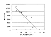
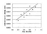
尚、上記かしめ部14の加工完了は、上記油圧シリンダの油圧室内の圧力が設定圧力になる事で検知する他、このかしめ部14のかしめ高さH(=前記内輪9aの軸方向一端面からの、このかしめ部14の突出量、図3参照)と、このかしめ部14の加工に伴う上記内輪9aの直径の拡大量との一方又は双方の測定値に基づいて検知する事もできる。上記円筒部16を上記かしめ部14に加工する際、このかしめ部14に対し上記内輪9aの軸方向に加えられる力(軸力=この内輪9aを軸方向に押圧する力)とかしめ高さHとの関係は図4に示す様になる。又、上記円筒部16を上記かしめ部14に加工する際、このかしめ部14に加える荷重の大きさ(荷重/最大荷重)と上記内輪9aの外径の拡大比(膨張量/直径)との関係は図5に示す様になる。これら図4、5中、符号「◆」は、第一のロットの車輪支持用転がり軸受ユニットの円筒部16を、特に変形し易い条件(硬さ及び体積が下限の条件)下で加工した場合を、符号「■」は、第二のロットに関して同じ条件で加工した場合を、符号「▲」は、第一のロットの車輪支持用転がり軸受ユニットの円筒部16を、特に変形しにくい条件(硬さ及び体積が上限の条件)下で加工した場合を、符号「●」は、第二のロットに関して同じ条件で加工した場合を、それぞれ示している。   The completion of the working of the caulking portion 14 is detected by detecting that the pressure in the hydraulic chamber of the hydraulic cylinder reaches a set pressure, and the caulking height H of the caulking portion 14 (= from one axial end surface of the inner ring 9a). The protruding amount of the caulking portion 14 (see FIG. 3) and the increase in the diameter of the inner ring 9a due to the processing of the caulking portion 14 can be detected based on one or both measured values. When the cylindrical portion 16 is processed into the caulking portion 14, a force applied to the caulking portion 14 in the axial direction of the inner ring 9a (axial force = force pressing the inner ring 9a in the axial direction) and a caulking height H Is as shown in FIG. When the cylindrical portion 16 is processed into the caulked portion 14, the magnitude of the load applied to the caulked portion 14 (load / maximum load) and the expansion ratio of the outer diameter of the inner ring 9a (expansion amount / diameter) are determined. The relationship is as shown in FIG. In FIGS. 4 and 5, the symbol “◆” indicates that the cylindrical portion 16 of the wheel supporting rolling bearing unit of the first lot is processed under particularly easily deformable conditions (hardness and volume are the lower limit conditions). The symbol “■” indicates the case where the second lot was processed under the same conditions, and the symbol “▲” indicates that the cylindrical portion 16 of the wheel supporting rolling bearing unit of the first lot was particularly hardly deformed ( The symbol "●" indicates the case where the processing was performed under the same conditions with respect to the second lot, and the case where the processing was performed under the condition that the hardness and the volume are the upper limits).

この様な図4、5から明らかな通り、上記軸力とかしめ高さHとの間、上記直径の拡大量とかしめ部14の加工時に加える荷重との間には、或る程度の関係が存在する。そこで、前記各転動体17a、17aに付与する予圧の面から、必要とする軸力の下限値を設定すると共に、この下限値を確保する為に必要とするかしめ高さHを求める。又、製造装置の能力(耐荷重)等から、採用し得る荷重の最大値(最大荷重)を設定し、この荷重を最大値以内に納められる、上記内輪9aの直径の拡大量(拡大比)の最大値を求める。そして、上記かしめ部14のかしめ高さHを、上記軸力の下限値を確保する為に必要とする値以下に、上記内輪9aの直径の拡大量が上記荷重を最大値以内に納められる値以下に、それぞれ納められる範囲内で、上記かしめ部14の加工を行なう。即ち、上記かしめ部14のかしめ高さHが所定の値以下に、上記拡大量が所定の値以下に、それぞれ収まった状態で、上記かしめ部14の加工を完了する。尚、これら所定の値は、予め実験により求めておく。この様にしてこのかしめ部14の加工を行なえば、上記製造装置を損傷する事なく、良質のかしめ部14を安定して成形できる。   As apparent from FIGS. 4 and 5, there is a certain relationship between the axial force and the swaging height H, and between the amount of increase in the diameter and the load applied during the working of the swaging portion 14. Exists. Therefore, from the viewpoint of the preload applied to the rolling elements 17a, 17a, the lower limit of the required axial force is set, and the crimping height H required to secure the lower limit is obtained. Also, the maximum value (maximum load) of the load that can be adopted is set from the capacity (load capacity) of the manufacturing apparatus and the like, and the amount of expansion of the diameter of the inner ring 9a (expansion ratio) that can keep this load within the maximum value Find the maximum value of. The caulking height H of the caulking portion 14 is set to be equal to or less than the value required to secure the lower limit value of the axial force, and the amount of expansion of the diameter of the inner ring 9a is set so that the load is within the maximum value. Hereinafter, the processing of the caulking portion 14 is performed within the range where each can be accommodated. That is, the processing of the caulking portion 14 is completed in a state where the caulking height H of the caulking portion 14 is less than a predetermined value and the enlargement amount is less than a predetermined value. Note that these predetermined values are obtained in advance by experiments. If the caulking portion 14 is processed in this manner, a high-quality caulking portion 14 can be formed stably without damaging the manufacturing apparatus.

このかしめ部14を安定して成形する為には、上記かしめ高さHと上記拡大量との双方を観察する事が好ましいが、何れか一方の値のみを測定し、この何れか一方の値が予め設定した範囲内に収まった状態で、上記かしめ部14の加工を完了する事もできる。この場合には、他方の値を勘案しつつ、予め実験により上記一方の値の許容範囲(最大値と最小値と)を設定しておき、この一方の値が許容範囲に収まった状態で、上記かしめ部14の加工を完了する。   In order to form the caulking portion 14 stably, it is preferable to observe both the caulking height H and the enlargement amount, but only one of the values is measured, and either one of the values is measured. The machining of the caulking section 14 can be completed in a state where the distance falls within a preset range. In this case, the allowable range (the maximum value and the minimum value) of the one value is set in advance by an experiment while considering the other value, and in a state where the one value falls within the allowable range, The processing of the caulking portion 14 is completed.

尚、上述の様にして行なう、上記かしめ部14の加工作業中は、特にかしめ加工の為の潤滑油等は使用しない。この理由は、この潤滑油等が上記車輪支持用転がり軸受ユニット内のグリースに混入し、このグリースを劣化させる事を防止する為である。但し、上記かしめ部14が加工しにくく、上記加圧ローラ35の損傷が著しくなる場合には、上記グリース中への混入防止を配慮した上で、潤滑油を使用する事もできる。   During the working of the caulking portion 14 performed as described above, no lubricating oil or the like is particularly used for caulking. The reason for this is to prevent the lubricating oil and the like from being mixed into the grease in the wheel supporting rolling bearing unit and deteriorating the grease. However, when the caulking portion 14 is difficult to work and the pressure roller 35 is significantly damaged, lubricating oil may be used in consideration of prevention of mixing in the grease.

又、上記加圧ローラ35と円筒部16とを突き当てた後、上記加圧ヘッド34を回転させる速度は、通常2〜10段階に調節自在とする。例えば、3段階に調節する場合、上記円筒部16のかしめ加工の開始直後は、1〜300min-1 の範囲に設定する。そして、このかしめ加工が進行した途中段階で、前記内輪9aの一部と、上記円筒部16が塑性変形する事で造られたかしめ部14が当接する直前に、200〜600min-1 に上昇させる。更に、上記かしめ加工が進行した最終段階で、上記かしめ部14が、上記内輪9aの一端面(図1の上端面)内周縁部に形成した面取り部43に当接した後は、500〜1500min-1 に上昇させる。より具体的には、開始直後に100〜300min-1 、途中段階で400〜600min-1 、最終段階で800〜1300min-1 にする。尚、好ましくは、これらの範囲内で、できる限り低速で(一般的には550min-1 以下で)上記加圧ヘッド34を回転させる事により、上記円筒部16を上記かしめ部14に加工するまでに要する総回転数を少なく(一般的には100回転以下)に抑える。この様に、この総回転数を少なく抑えれば、上記加圧ローラ35の摩耗を低減し、上記かしめ部14の品質向上と車輪支持用転がり軸受ユニットの製造装置の耐久性向上とを図れる。 The speed at which the pressure head 34 is rotated after the pressure roller 35 comes into contact with the cylindrical portion 16 is normally adjustable in two to ten steps. For example, when adjusting in three stages, immediately after the start of the caulking of the cylindrical portion 16, the range is set to 1 to 300 min −1 . Then, in the middle stage of the caulking, the inner ring 9a is raised to 200 to 600 min -1 immediately before the caulking portion 14 formed by plastically deforming the cylindrical portion 16 and the cylindrical portion 16 abuts. . Further, at the final stage of the caulking process, after the caulked portion 14 comes into contact with the chamfered portion 43 formed on the inner peripheral edge of one end face (the upper end face in FIG. 1) of the inner ring 9a, it is 500 to 1500 min. Increase to -1 . More specifically, 100~300Min -1 immediately after the start, 400~600Min -1 halfway stage, to 800~1300Min -1 in the final stage. It is preferable that the cylindrical portion 16 is processed into the caulked portion 14 by rotating the pressure head 34 at the lowest possible speed (generally, 550 min -1 or less) within these ranges. The total number of rotations required for the rotation is kept low (generally 100 rotations or less). As described above, if the total number of rotations is reduced, the wear of the pressure roller 35 is reduced, and the quality of the caulked portion 14 and the durability of the manufacturing apparatus of the rolling bearing unit for supporting the wheel can be improved.

加圧ヘッド34の回転速度を上述の様に調節すれば、この加圧ヘッド34の1回転毎の圧下量(1回転毎にハブ2aに向け下降する長さ)を、前半は大きく、後半は小さくできる。この様に、上記円筒部16の変形量を多くしても問題を生じにくい、加工作業の前半は圧下量を大きくして、かしめ部14の加工作業の能率向上を図る。これに対して、後半は、回転数を速くして圧下量を小さくし、上記円筒部16乃至はかしめ部14の変形を局所的に抑えて、内輪9aの外周面に設けた第二の内輪軌道12aやハブ本体8aの中心部に設けたスプライン孔32にまで変形する事を防止する。従って、車輪支持用転がり軸受ユニットの構造により、この様な変形防止を考慮する必要がなければ、上記加圧ヘッド34の回転速度を、200〜1500min-1 の一定のまま、かしめ加工を行なっても良い。 If the rotation speed of the pressure head 34 is adjusted as described above, the reduction amount of the pressure head 34 per rotation (the length of the pressure head 34 falling toward the hub 2a per rotation) is large in the first half and large in the second half. Can be smaller. As described above, even if the deformation amount of the cylindrical portion 16 is increased, a problem does not easily occur. In the first half of the working operation, the reduction amount is increased to improve the efficiency of the working operation of the caulking portion 14. On the other hand, in the latter half, the rotation speed is increased to reduce the rolling reduction, the deformation of the cylindrical portion 16 to the caulking portion 14 is locally suppressed, and the second inner ring provided on the outer peripheral surface of the inner ring 9a is provided. This prevents deformation of the track 12a and the spline hole 32 provided in the center of the hub body 8a. Therefore, according to the structure of the rolling bearing unit for supporting the wheel, if it is not necessary to consider such prevention of deformation, caulking is performed while the rotation speed of the pressure head 34 is kept constant at 200 to 1500 min -1. Is also good.

尚、図示の例では、前記加圧ローラ35の中心軸と、上記ハブ2a及び加圧ヘッド34の中心軸との交差角度γを90度としているが、45〜120度の範囲で採用可能である。但し、前述した様に、油圧シリンダ等の押圧手段の出力を上記加圧ローラ35から上記円筒部16乃至はかしめ部14に向け、効率良く加える為には、上記交差角度γは、70〜110度の範囲に規制する事が好ましい。尚、上記ハブ2aの中心軸と上記加圧ヘッド34の中心軸とを一致させない場合でも、上記加圧ローラ35の中心軸と上記加圧ヘッド34の中心軸との交差角度に関しても、70〜110度の範囲に規制する事が好ましい。尚、上記加圧ローラ35が1個の場合には、上記交差角度γを1〜45度の範囲に設定する場合もある。   In the illustrated example, the intersection angle γ between the central axis of the pressure roller 35 and the central axes of the hub 2a and the pressure head 34 is 90 degrees, but can be adopted in the range of 45 to 120 degrees. is there. However, as described above, in order to efficiently apply the output of the pressing means such as a hydraulic cylinder from the pressure roller 35 to the cylindrical portion 16 to the caulking portion 14, the crossing angle γ should be 70 to 110. It is preferable to regulate the temperature within the range. Even when the center axis of the hub 2a does not coincide with the center axis of the pressure head 34, the intersection angle between the center axis of the pressure roller 35 and the center axis of the pressure head 34 is also 70 to It is preferable to restrict the angle to a range of 110 degrees. When the number of the pressure rollers 35 is one, the intersection angle γ may be set in a range of 1 to 45 degrees.

尚、かしめ作業の間中、車輪支持用転がり軸受ユニットは、図1に示す様に、径方向に拘束しない。この理由は、かしめ作業に伴ってこの車輪支持用転がり軸受ユニットが揺れた(径方向に変位した)場合に、径方向の拘束があるとエネルギーロスが生じる場合がある為、このロスを無くして、効率の良いかしめ作業を行なわせる為である。尚、上記車輪支持用転がり軸受ユニットを径方向に拘束しない場合には、支持台33に就いても、径方向に拘束しない。但し、ハブ2aが過度に揺動したり振動したりして、上記円筒部16の塑性加工を安定して行なえない場合には、上記内輪9aを径方向に拘束しても良い。   During the caulking operation, the wheel supporting rolling bearing unit is not restrained in the radial direction as shown in FIG. The reason for this is that when the rolling bearing unit for wheel support swings (displaces in the radial direction) during the caulking operation, energy loss may occur if there is a restriction in the radial direction. It is for performing efficient caulking work. When the rolling bearing unit for supporting the wheel is not constrained in the radial direction, the support base 33 is not constrained in the radial direction. However, if the hub 2a swings or vibrates excessively and the plastic working of the cylindrical portion 16 cannot be performed stably, the inner ring 9a may be restrained in the radial direction.

又、上記加圧ローラ35の材質は、工具鋼等の超硬鋼、ダイス鋼、或はセラミックを使用する。又、加圧ローラ35に、摩耗防止の為のコーティングを施す事も有効である。更には、空気や油(ミスト状態)等の冷却用の流体(冷却流体)をかしめ加工部に吹き付けながらかしめ作業を行ない、このかしめ加工部の温度上昇を抑える事も、上記加圧ローラ35の寿命を向上させる面から効果がある。   The material of the pressure roller 35 is a carbide steel such as tool steel, a die steel, or a ceramic. It is also effective to apply a coating to the pressure roller 35 to prevent wear. Further, the caulking operation is performed while spraying a cooling fluid (cooling fluid) such as air or oil (in a mist state) to the caulking portion to suppress a rise in the temperature of the caulking portion. It is effective in improving the life.

又、前記ローラ保持部38の奥面に開口させた吸気口から空気を吸い込む事により、かしめ加工により生じる摩耗粉を取り除く事も、上記加圧ローラ35の寿命を向上させ、且つ、上記かしめ部14の品質を良好にして、車輪支持用転がり軸受ユニットの歩留を向上させる面から効果がある。更には、かしめ加工中、或はかしめ加工の前後に、ブラシを使って、上記加圧ローラ35に付着した摩耗粉を除去する事も、上記加圧ローラ35の寿命向上と車輪支持用転がり軸受ユニットの歩留向上との面から効果がある。   In addition, by removing the abrasion powder generated by the caulking process by sucking air from an intake port opened on the inner surface of the roller holding portion 38, the life of the pressure roller 35 can be improved, and the caulking portion can be removed. This is effective in improving the quality of No. 14 and improving the yield of the rolling bearing unit for supporting wheels. Further, it is also possible to use a brush to remove wear powder adhering to the pressure roller 35 during or before and after the caulking process, thereby improving the life of the pressure roller 35 and rolling bearings for supporting wheels. This is effective in terms of improving the unit yield.

尚、本実施例の製造方法は、図示の様なスプライン孔32を備えた車輪支持用転がり軸受ユニットの製造に適用した場合の他、前述の図8、9、10、13に示す様な、転動体17、17として円すいころを使用した車輪支持用転がり軸受ユニットの製造に適用した場合に、特に効果を発揮する。円すいころを使用した車輪支持用転がり軸受ユニットのかしめ部を、前述した従来構造の様に、一般的な揺動かしめにより行なうと、内輪9の外周面に形成した第二の内輪軌道12のクラウニングが変形し、この第二の内輪軌道12と転動体17、17の転動面との転がり接触部にエッジロードが生じる可能性がある。これに対して本実施例の製造方法を採用すれば、前述した様に、円筒部16乃至はかしめ部14が局所的に変形して、上記第二の内輪軌道12にまで変形が及びにくい。従って、上記エッジロードが生じにくくなる。ハブ本体8aに設けたスプライン孔32に関しても、同様の理由により変形が及びにくくなって、このスプライン孔32と、等速ジョイントの付属のスプライン孔との係合状態を良好にできる。   The manufacturing method according to the present embodiment is applied to the manufacture of a wheel supporting rolling bearing unit having a spline hole 32 as shown in FIG. This is particularly effective when applied to the manufacture of a wheel supporting rolling bearing unit using tapered rollers as the rolling elements 17 and 17. When the caulking portion of the wheel supporting rolling bearing unit using the tapered rollers is performed by general rocking as in the above-described conventional structure, crowning of the second inner raceway 12 formed on the outer peripheral surface of the inner race 9 is performed. May be deformed, and an edge load may occur at a rolling contact portion between the second inner raceway 12 and the rolling surfaces of the rolling elements 17 and 17. On the other hand, if the manufacturing method of the present embodiment is adopted, the cylindrical portion 16 to the caulking portion 14 are locally deformed as described above, so that it is difficult to deform to the second inner raceway 12. Therefore, the edge load hardly occurs. The spline hole 32 provided in the hub main body 8a is hardly deformed for the same reason, and the engagement between the spline hole 32 and the spline hole attached to the constant velocity joint can be improved.

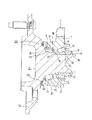
図6は、本発明の実施例2を示している。本実施例の場合には、かしめ部14の加工時にハブ2aを支承する為の支持台33aの直径を、上述した実施例1の場合に比べて小さくしている。そして、この支持台33aの上端面を、上記ハブ2aの一端面(車両への組み付け状態で車両の幅方向外側となる端面)で位置決め筒部36よりも内径側部分に突き当てている。その他の構成及び作用は、上述した実施例1の場合と同様である。   FIG. 6 shows a second embodiment of the present invention. In the case of the present embodiment, the diameter of the support 33a for supporting the hub 2a when the caulking portion 14 is processed is smaller than that of the above-described first embodiment. Then, the upper end surface of the support base 33a is abutted on one end surface of the hub 2a (the end surface which is outside in the width direction of the vehicle in an assembled state with the vehicle) on the inner diameter side portion with respect to the positioning cylinder portion 36. Other configurations and operations are the same as those in the first embodiment.

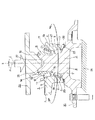
図7は、本発明の実施例3を示している。本実施例の場合には、かしめ部14の加工時にハブ2aを支承する為の支持台33bの直径を、上述した実施例1の場合に比べて大きくしている。そして、この支持台33bの上端面を、上記ハブ2aの一端部(車両への組み付け状態で車両の幅方向外側となる端部)に形成したフランジ10の側面に突き当てている。このフランジ10に固定したスタッド44は、上記支持台33bの一部に形成した孔部45に挿入して、上記支持台33bの上端面と上記フランジ10の側面とを密接させている。その他の構成及び作用は、前述した実施例1の場合と同様である。   FIG. 7 shows a third embodiment of the present invention. In the case of the present embodiment, the diameter of the support 33b for supporting the hub 2a during the processing of the caulked portion 14 is made larger than in the case of the first embodiment described above. Then, the upper end surface of the support base 33b abuts against the side surface of the flange 10 formed at one end of the hub 2a (the end that is located outside in the width direction of the vehicle when assembled to the vehicle). The stud 44 fixed to the flange 10 is inserted into a hole 45 formed in a part of the support base 33b, so that the upper end surface of the support base 33b and the side surface of the flange 10 are in close contact. Other configurations and operations are the same as those of the first embodiment.

本発明の如き製造方法及び製造装置は、車輪支持用転がり軸受ユニットの製造に限らず、あらゆる円筒部を有するブランクの加締め加工、或いは塑性加工に適用可能である。即ち、本発明は、従来のローリングプレス機(揺動プレス機)で加工していた製品に就いては、車輪支持用転がり軸受ユニットに限らずに適用可能である。又、車輪支持用転がり軸受ユニットの製造に使用する場合でも、図示の様な内輪回転型の構造に限らず、外輪回転型の構造の製造にも適用できる。この場合には、かしめ部は、懸架装置に支持した状態で回転しない軸部材の一端(車両への組み付け状態で車両の幅方向外側となる端)部に形成する。   The manufacturing method and the manufacturing apparatus according to the present invention can be applied to not only the manufacturing of the wheel bearing rolling bearing unit but also to the crimping or plastic working of a blank having any cylindrical portion. That is, the present invention is applicable not only to the rolling bearing unit for supporting wheels, but also to a product processed by a conventional rolling press (oscillating press). Further, even when the present invention is used to manufacture a rolling bearing unit for supporting a wheel, the present invention is not limited to the structure of the inner ring rotating type as shown in the figure, but can be applied to the manufacture of an outer ring rotating type structure. In this case, the caulking portion is formed at one end of the shaft member that does not rotate while being supported by the suspension device (the end that is the outer side in the width direction of the vehicle when assembled to the vehicle).

本発明の実施例1を、かしめ部を加工する状態で示す断面図。Sectional drawing which shows Example 1 of this invention in the state which processes a crimping part. 同じく加圧ローラと軸部材とを取り出した状態で示す斜視図。FIG. 3 is a perspective view showing a state in which a pressure roller and a shaft member are taken out. かしめ高さHを説明する為の、車輪支持用転がり軸受ユニットの半部断面図。FIG. 3 is a half sectional view of a wheel supporting rolling bearing unit for explaining a swaging height H; かしめ高さHと内輪に加わる軸力との関係を示すグラフ。4 is a graph showing a relationship between a swaging height H and an axial force applied to an inner ring. かしめ部の加工の為に加える荷重と内輪の外径の拡大量との関係を示すグラフ。4 is a graph showing a relationship between a load applied for processing a swaged portion and an amount of expansion of an outer diameter of an inner ring. 本発明の実施例2を、かしめ部を加工する状態で示す断面図。Sectional drawing which shows Example 2 of this invention in the state which processes a crimping part. 本発明の実施例3を、かしめ部を加工する状態で示す断面図。Sectional drawing which shows Example 3 of this invention in the state which processes a crimping part. 従来から知られている車輪支持用転がり軸受ユニットの1例を示す断面図。Sectional drawing which shows an example of the conventionally known rolling bearing unit for wheel support. 従来から知られている車輪支持用転がり軸受ユニットの製造方法の第1例でハブに対して内輪を外嵌固定する状態を示す断面図。Sectional drawing which shows the state which fits and fixes an inner ring to a hub in the 1st example of the manufacturing method of the rolling bearing unit for wheel support conventionally known. 同じくかしめ部を形成する状態を示す断面図。Sectional drawing which shows the state which forms a crimping part similarly. 押型が円筒部若しくはかしめ部を押圧する部分の円周方向に関する曲率を大きくした構造を示す断面図。Sectional drawing which shows the structure which made the curvature in the circumferential direction of the part which a press die presses a cylindrical part or a crimping part. 図11のA−A断面図。AA sectional drawing of FIG. 図11に示した構造に類似する構造として従来から知られている構造の1例を示す断面図。FIG. 12 is a sectional view showing an example of a structure conventionally known as a structure similar to the structure shown in FIG. 11.

符号の説明Explanation of reference numerals

1、1a 外輪
2、2a ハブ
3、3a 第一列の転がり軸受
4、4a 第二列の転がり軸受
5、5a 第一の外輪軌道
6、6a 第二の外輪軌道
7 取付部
8、8a ハブ本体
9、9a 内輪
10 フランジ
11、11a 第一の内輪軌道
12、12a 第二の内輪軌道
13 段部
14 かしめ部
15 段差面
16 円筒部
17、17a 転動体
18 第一の保持器
19 第二の保持器
20 シールリング
21 空間
22 芯金
23 弾性材
24 支持台
25 圧入治具
26、26a 押型
27 凸部
28、28a 凹部
29 支持軸受
30 ロール
31 凹部
32 スプライン孔
33、33a、33b 支持台
34 加圧ヘッド
35 加圧ローラ
36 位置決め筒部
37 凹部
38 ローラ保持部
39 枢軸
40 加工部
41 凹部
42 ラジアル軸受
43 面取り部
44 スタッド
45 孔部
1, 1a Outer ring 2, 2a Hub 3, 3a Rolling bearing in first row 4, 4a Rolling bearing in second row 5, 5a First outer ring track 6, 6a Second outer ring track 7 Mounting part 8, 8a Hub body 9, 9a Inner ring 10 Flange 11, 11a First inner ring track 12, 12a Second inner ring track 13 Step 14 Caulking section 15 Step surface 16 Cylindrical section 17, 17a Rolling element 18 First retainer 19 Second retainer Container 20 Seal ring 21 Space 22 Core bar 23 Elastic material 24 Support stand 25 Press-in jig 26, 26a Pressing die 27 Convex part 28, 28a Concave part 29 Support bearing 30 Roll 31 Concave part 32 Spline hole 33, 33a, 33b Support stand 34 Press Head 35 Pressure roller 36 Positioning cylinder 37 Depression 38 Roller holding part 39 Axis 40 Processing part 41 Depression 42 Radial bearing 43 Chamfer 4 stud 45 holes

Claims (14)

内周面に第一、第二の外輪軌道を有する外径側軌道輪部材と、外周面に第一、第二の内輪軌道を有する内径側軌道輪部材と、これら第一、第二の内輪軌道と上記第一、第二の外輪軌道との間にそれぞれ複数個ずつ転動自在に設けられた転動体とを備え、上記内径側軌道輪部材は、その中間部外周面に直接又は別体の内輪を介して上記第一の内輪軌道を設けた軸部材と、その外周面に上記第二の内輪軌道を設けた内輪とから成り、この内輪は、上記軸部材の一端部に外嵌し、更にこの軸部材の一端部に設けた円筒部を直径方向外方に塑性変形させる事で形成したかしめ部によりその軸方向一端面を抑え付けられる事で、上記軸部材に対し支持固定されている車輪支持用転がり軸受ユニットを造る為、加圧部材により上記円筒部の円周方向の一部に、軸方向に関して他端側に、径方向に関して外方に、それぞれ向いた荷重を加えると共に、この荷重を加える部分を上記円筒部の円周方向に関して連続的に変化させる事により、この円筒部を徐々に塑性変形させて、上記かしめ部とする車輪支持用転がり軸受ユニットの製造方法に於いて、上記加圧部材が加圧ローラであり、この加圧ローラの中心軸を含む仮想平面に関するこの加圧ローラの外周面の断面形状が、上記かしめ部の外面の断面形状に見合う形状であり、この加圧ローラをその中心軸を自転軸として自転させつつ上記軸部材の中心軸の周囲を公転させながら上記加圧ローラをこの軸部材に向け押し付けて、上記円筒部を塑性変形させる事を特徴とする車輪支持用転がり軸受ユニットの製造方法。   Outer diameter side bearing ring members having first and second outer ring raceways on the inner peripheral surface, inner diameter side bearing ring members having first and second inner ring raceways on the outer peripheral surface, and these first and second inner rings A plurality of rolling elements respectively provided between the raceway and the first and second outer raceways so as to freely roll, the inner raceway ring member being directly or separately formed on the outer peripheral surface of the intermediate portion thereof. A shaft member provided with the first inner raceway through the inner race, and an inner race provided with the second inner raceway on the outer peripheral surface thereof, and the inner race is externally fitted to one end of the shaft member. Further, the cylindrical portion provided at one end of the shaft member is plastically deformed outward in the diametrical direction so that one end surface in the axial direction can be suppressed by the caulking portion, so that the cylindrical portion is supported and fixed to the shaft member. To make a rolling bearing unit for wheel support, a part of the cylindrical part in the circumferential direction by a pressing member. By applying a load directed toward the other side in the axial direction and outward in the radial direction, and by continuously changing the portion to which the load is applied in the circumferential direction of the cylindrical portion, the cylindrical portion is formed. In the method of manufacturing a rolling bearing unit for supporting a wheel, which is gradually plastically deformed to be a caulking portion, the pressing member is a pressing roller, and the pressing member is a pressing roller with respect to a virtual plane including a central axis of the pressing roller. The cross-sectional shape of the outer peripheral surface of the pressure roller is a shape corresponding to the cross-sectional shape of the outer surface of the caulking portion, and revolves around the central axis of the shaft member while rotating the pressure roller with its central axis as the rotation axis. A method of manufacturing a rolling bearing unit for supporting wheels, wherein the pressure roller is pressed against the shaft member while plastically deforming the cylindrical portion. 加圧ローラの自転軸の延長線が軸部材の中心線の延長線と直交する、請求項1に記載した車輪支持用転がり軸受ユニットの製造方法。   The method of manufacturing a rolling bearing unit for supporting a wheel according to claim 1, wherein an extension of a rotation shaft of the pressure roller is orthogonal to an extension of a center line of the shaft member. 加圧ローラを軸部材の中心軸の周囲に複数個、円周方向に関して等間隔に配置し、これら複数個の加圧ローラをこの中心軸の周りで互いに同期させて公転させつつ自転させる事により、円筒部を円周方向複数個所で同時に塑性変形させる、請求項1〜2の何れかに記載した車輪支持用転がり軸受ユニットの製造方法。   By arranging a plurality of pressure rollers around the center axis of the shaft member at equal intervals in the circumferential direction, and by rotating the plurality of pressure rollers around the center axis while revolving in synchronization with each other. 3. The method for manufacturing a wheel-supporting rolling bearing unit according to claim 1, wherein the cylindrical portion is plastically deformed simultaneously at a plurality of positions in the circumferential direction. 円筒部を冷却流体により冷却しつつ塑性変形させる、請求項1〜3の何れかに記載した車輪支持用転がり軸受ユニットの製造方法。   The method of manufacturing a rolling bearing unit for supporting a wheel according to any one of claims 1 to 3, wherein the cylindrical portion is plastically deformed while being cooled by a cooling fluid. 加圧ローラと円筒部との接触により生じてこの円筒部に付着する摩耗粉を除去しつつ、この円筒部を塑性変形させる、請求項1〜4の何れかに記載した車輪支持用転がり軸受ユニットの製造方法。   The rolling bearing unit for wheel support according to any one of claims 1 to 4, wherein the cylindrical portion is plastically deformed while removing wear powder generated by contact between the pressure roller and the cylindrical portion and adhering to the cylindrical portion. Manufacturing method. 加圧ローラと円筒部との接触により生じてこの加圧ローラに付着する摩耗粉を除去しつつ、この円筒部を塑性変形させる、請求項1〜5の何れかに記載した車輪支持用転がり軸受ユニットの製造方法。   The wheel bearing according to any one of claims 1 to 5, wherein the cylindrical portion is plastically deformed while removing wear powder generated by contact between the pressure roller and the cylindrical portion and adhering to the pressure roller. Unit manufacturing method. 加圧ローラと円筒部との接触により生じてこの加圧ローラに付着する摩耗粉を、この円筒部を塑性変形させる加工工程の前又は後に除去する、請求項1〜5の何れかに記載した車輪支持用転がり軸受ユニットの製造方法。   The wear powder generated by the contact between the pressure roller and the cylindrical portion and attached to the pressure roller is removed before or after a processing step of plastically deforming the cylindrical portion, according to any one of claims 1 to 5. A method for manufacturing a rolling bearing unit for supporting a wheel. 加圧ローラの公転速度及び自転速度を、円筒部をかしめ部にまで塑性変形する途中で変化させる、請求項1〜7の何れかに記載した車輪支持用転がり軸受ユニットの製造方法。   The method of manufacturing a rolling bearing unit for wheel support according to any one of claims 1 to 7, wherein the revolution speed and the rotation speed of the pressure roller are changed during the plastic deformation of the cylindrical portion to the caulking portion. 内輪の軸方向一端面からのかしめ部の突出量と、このかしめ部の加工に伴う内輪の直径の拡大量とを測定し、これら突出量と拡大量とが予め設定した範囲内に収まった状態で、軸部材に対する加圧ローラの押し付けを終了する、請求項1〜8の何れかに記載した車輪支持用転がり軸受ユニットの製造方法。   Measure the amount of protrusion of the caulked portion from one end surface in the axial direction of the inner ring and the amount of increase in the diameter of the inner ring due to the processing of the caulked portion, and the amount of protrusion and the amount of expansion are within a preset range. 9. The method of manufacturing a wheel-supporting rolling bearing unit according to claim 1, wherein pressing of the pressure roller against the shaft member is terminated. 内輪の軸方向一端面からのかしめ部の突出量と、このかしめ部の加工に伴う内輪の直径の拡大量とのうちの何れか一方の値を測定し、この何れか一方の値が予め設定した範囲内に収まった状態で、軸部材に対する加圧ローラの押し付けを終了する、請求項1〜8の何れかに記載した車輪支持用転がり軸受ユニットの製造方法。   Measure the value of any one of the amount of protrusion of the caulked portion from one end surface in the axial direction of the inner ring and the amount of increase in the diameter of the inner ring due to the processing of the caulked portion, and one of these values is set in advance. 9. The method of manufacturing a wheel-supporting rolling bearing unit according to claim 1, wherein the pressing of the pressure roller against the shaft member is completed in a state where the pressure falls within the range set forth above. 請求項1〜10の何れかに記載した車輪支持用転がり軸受ユニットの製造方法を実施する為、内径側軌道輪部材の他端部を支える支持台と、この支持台の上方に昇降及び回転自在に設けられた加圧ヘッドと、この加圧ヘッドの下端部で上記内径側軌道輪部材の円筒部に対向する部分に、この内径側軌道輪部材の直径方向に配置された枢軸を中心とする自転自在に支持された少なくとも1個の加圧ローラとを備えた、車輪支持用転がり軸受ユニットの製造装置。   In order to carry out the method for manufacturing a rolling bearing unit for supporting a wheel according to any one of claims 1 to 10, a support base for supporting the other end of the inner raceway ring member, and a vertically movable and rotatable upper part of the support base. And a pressurizing head provided at the lower end of the pressurizing head, which is opposed to the cylindrical portion of the inner raceway member, about a pivot disposed in the diameter direction of the inner raceway member. An apparatus for manufacturing a wheel-supporting rolling bearing unit, comprising at least one pressure roller rotatably supported. 加圧ヘッドが、支持台上に載置された内径側軌道輪部材と同心の中心軸を中心とする回転自在であり、加圧ローラは、上記加圧ヘッドの下端部にこの中心よりも外径に寄った部分に設けられている、請求項11に記載した車輪支持用転がり軸受ユニットの製造装置。   The pressure head is rotatable around a central axis concentric with the inner race member mounted on the support table, and the pressure roller is disposed at the lower end of the pressure head outside the center. The manufacturing apparatus of a rolling bearing unit for wheel support according to claim 11, wherein the rolling bearing unit is provided at a portion closer to the diameter. 加圧ローラは、軸方向両端を加圧ヘッドの下端部に回転自在に支持されている、請求項11〜12の何れかに記載した車輪支持用転がり軸受ユニットの製造装置。   The manufacturing apparatus of a rolling bearing unit for supporting wheels according to any one of claims 11 to 12, wherein both ends of the pressure roller in the axial direction are rotatably supported by lower ends of the pressure head. 加圧ローラの外周面と円筒部の先端部とが当接する瞬間に加圧ヘッドに加わる衝撃を吸収する衝撃吸収手段を備えた、請求項11〜13の何れかに記載した車輪支持用転がり軸受ユニットの製造装置。   The wheel bearing according to any one of claims 11 to 13, further comprising an impact absorbing means for absorbing an impact applied to the pressure head at the moment when the outer peripheral surface of the pressure roller and the tip of the cylindrical portion come into contact with each other. Unit manufacturing equipment.
JP2003350898A 2002-10-21 2003-10-09 Method for manufacturing rolling bearing unit for supporting wheel, and manufacturing apparatus Withdrawn JP2004162913A (en)

Priority Applications (1)

Application Number Priority Date Filing Date Title
JP2003350898A JP2004162913A (en) 2002-10-21 2003-10-09 Method for manufacturing rolling bearing unit for supporting wheel, and manufacturing apparatus

Applications Claiming Priority (2)

Application Number Priority Date Filing Date Title
JP2002305388 2002-10-21
JP2003350898A JP2004162913A (en) 2002-10-21 2003-10-09 Method for manufacturing rolling bearing unit for supporting wheel, and manufacturing apparatus

Publications (2)

Publication Number Publication Date
JP2004162913A true JP2004162913A (en) 2004-06-10
JP2004162913A5 JP2004162913A5 (en) 2006-11-09

Family

ID=32828013

Family Applications (1)

Application Number Title Priority Date Filing Date
JP2003350898A Withdrawn JP2004162913A (en) 2002-10-21 2003-10-09 Method for manufacturing rolling bearing unit for supporting wheel, and manufacturing apparatus

Country Status (1)

Country Link
JP (1) JP2004162913A (en)

Cited By (11)

* Cited by examiner, † Cited by third party
Publication number Priority date Publication date Assignee Title
WO2006057252A1 (en) * 2004-11-26 2006-06-01 Jtekt Corporation Rolling bearing device for wheel, method of producing the same, and turning apparatus for bearing member
JP2006153087A (en) * 2004-11-26 2006-06-15 Jtekt Corp Rolling bearing device and its manufacturing method
JP2008162568A (en) * 2006-12-06 2008-07-17 Nsk Ltd Wheel supporting double row rolling bearing unit, and manufacturing method thereof
JP2008223872A (en) * 2007-03-12 2008-09-25 Jtekt Corp Method for manufacturing hub unit
CN102256720A (en) * 2008-12-19 2011-11-23 谢夫勒科技有限两合公司 Rotary forming method for producing a rivet flange
WO2015056413A1 (en) * 2013-10-17 2015-04-23 日本精工株式会社 Method for producing wheel-supporting roller bearing unit
JP2016060267A (en) * 2014-09-15 2016-04-25 株式会社ジェイテクト Hub unit manufacturing device
JP2017106510A (en) * 2015-12-08 2017-06-15 日本精工株式会社 Manufacturing method of rolling bering unit and manufacturing device of rolling bearing unit
EP3323525A4 (en) * 2015-07-13 2019-03-27 NSK Ltd. Method and device for manufacuturing bearing unit
WO2021033710A1 (en) * 2019-08-20 2021-02-25 日本精工株式会社 Method for manufacturing hub unit bearing, swinging crimping device, and method for manufacturing vehicle
JP7031802B1 (en) * 2020-09-24 2022-03-08 日本精工株式会社 Caulking device and caulking method for bearing unit, hub unit bearing manufacturing method and manufacturing device, vehicle manufacturing method

Cited By (25)

* Cited by examiner, † Cited by third party
Publication number Priority date Publication date Assignee Title
WO2006057252A1 (en) * 2004-11-26 2006-06-01 Jtekt Corporation Rolling bearing device for wheel, method of producing the same, and turning apparatus for bearing member
JP2006153087A (en) * 2004-11-26 2006-06-15 Jtekt Corp Rolling bearing device and its manufacturing method
US7886441B2 (en) 2004-11-26 2011-02-15 Jtekt Corporation Method of manufacturing a rolling bearing device having identification information
JP4678174B2 (en) * 2004-11-26 2011-04-27 株式会社ジェイテクト Method for manufacturing rolling bearing device
US8534923B2 (en) 2004-11-26 2013-09-17 Jtekt Corporation Rolling bearing device for a road-wheel, a method of manufacturing the same and a turning apparatus for a bearing member
JP2008162568A (en) * 2006-12-06 2008-07-17 Nsk Ltd Wheel supporting double row rolling bearing unit, and manufacturing method thereof
JP2008223872A (en) * 2007-03-12 2008-09-25 Jtekt Corp Method for manufacturing hub unit
CN102256720A (en) * 2008-12-19 2011-11-23 谢夫勒科技有限两合公司 Rotary forming method for producing a rivet flange
CN102256720B (en) * 2008-12-19 2014-09-17 谢夫勒科技股份两合公司 Rotary forming method for producing a rivet flange
CN105531050A (en) * 2013-10-17 2016-04-27 日本精工株式会社 Method for producing wheel-supporting roller bearing unit
WO2015056413A1 (en) * 2013-10-17 2015-04-23 日本精工株式会社 Method for producing wheel-supporting roller bearing unit
JP2015077616A (en) * 2013-10-17 2015-04-23 日本精工株式会社 Manufacturing method of wheel support rolling bearing unit
EP3059027A4 (en) * 2013-10-17 2017-08-09 NSK Ltd. Method for producing wheel-supporting roller bearing unit
US10286727B2 (en) 2013-10-17 2019-05-14 Nsk Ltd. Method for producing wheel-supporting roller bearing unit
JP2016060267A (en) * 2014-09-15 2016-04-25 株式会社ジェイテクト Hub unit manufacturing device
US11162538B2 (en) 2015-07-13 2021-11-02 Nsk Ltd. Method and device for manufacturing bearing unit
EP3323525A4 (en) * 2015-07-13 2019-03-27 NSK Ltd. Method and device for manufacuturing bearing unit
US10557505B2 (en) 2015-07-13 2020-02-11 Nsk Ltd. Method and device for manufacturing bearing unit
JP2017106510A (en) * 2015-12-08 2017-06-15 日本精工株式会社 Manufacturing method of rolling bering unit and manufacturing device of rolling bearing unit
JP2021032269A (en) * 2019-08-20 2021-03-01 日本精工株式会社 Method for manufacturing hub unit bearing, oscillation caulking device and method for manufacturing vehicle
WO2021033710A1 (en) * 2019-08-20 2021-02-25 日本精工株式会社 Method for manufacturing hub unit bearing, swinging crimping device, and method for manufacturing vehicle
US11796006B2 (en) 2019-08-20 2023-10-24 Nsk Ltd. Method for manufacturing hub unit bearing, swaging device, and method for manufacturing vehicle
JP7031802B1 (en) * 2020-09-24 2022-03-08 日本精工株式会社 Caulking device and caulking method for bearing unit, hub unit bearing manufacturing method and manufacturing device, vehicle manufacturing method
WO2022064770A1 (en) 2020-09-24 2022-03-31 日本精工株式会社 Swaging device and swaging method for bearing unit, hub unit bearing manufacturing method and manufacturing device, and vehicle manufacturing method
KR20230072473A (en) 2020-09-24 2023-05-24 닛본 세이고 가부시끼가이샤 Caulk device and method for bearing units, method and method for manufacturing hub unit bearings, and method for manufacturing vehicles

Similar Documents

Publication Publication Date Title
JP6624354B1 (en) Oscillation processing device, method of manufacturing hub unit bearing, and method of manufacturing automobile
US6796714B2 (en) Rolling-bearing unit for wheel support
WO2017010481A1 (en) Method and device for manufacuturing bearing unit
US7121003B2 (en) Manufacturing method and manufacturing apparatus for wheel-support rolling bearing unit
JP2004162913A (en) Method for manufacturing rolling bearing unit for supporting wheel, and manufacturing apparatus
JP6555426B2 (en) Hub unit bearing and manufacturing method thereof, and automobile and manufacturing method thereof
JP2017018991A (en) Manufacturing method of rolling bearing unit
JP4822213B2 (en) Wheel bearing outer race
JP2007321939A (en) Bearing assembling method, rolling bearing, and cage for bearing
JP2003028179A (en) Manufacturing method and manufacturing device for wheel supporting rolling bearing unit
US20220055089A1 (en) Method of manufacturing staking assembly, method of manufacturing hub unit bearing, staking device, staking assembly, and method of manufacturing vehicle
JP2015028372A (en) Rolling bearing unit for supporting wheel
US20230296136A1 (en) Staking apparatus and staking method for bearing unit, manufacturing method and manufacturing apparatus of hub unit bearing, and manufacturing method of vehicle
JP2003083353A (en) Method/device of manufacturing rolling bearing unit for supporting wheel
JP6940011B2 (en) Manufacturing method of caulking assembly, manufacturing method of hub unit bearing, caulking device, caulking assembly, and manufacturing method of vehicle
JP2011140302A (en) Bearing device for vehicle
JP2007321988A (en) Vehiclular bearing apparatus
JP2008095715A (en) Bearing unit

Legal Events

Date Code Title Description
A521 Written amendment

Free format text: JAPANESE INTERMEDIATE CODE: A523

Effective date: 20060927

A621 Written request for application examination

Free format text: JAPANESE INTERMEDIATE CODE: A621

Effective date: 20060927

RD04 Notification of resignation of power of attorney

Free format text: JAPANESE INTERMEDIATE CODE: A7424

Effective date: 20060927

A761 Written withdrawal of application

Free format text: JAPANESE INTERMEDIATE CODE: A761

Effective date: 20090521