JP2017001776A - Jib expanding and storing mechanism - Google Patents
Jib expanding and storing mechanism Download PDFInfo
- Publication number
- JP2017001776A JP2017001776A JP2015115020A JP2015115020A JP2017001776A JP 2017001776 A JP2017001776 A JP 2017001776A JP 2015115020 A JP2015115020 A JP 2015115020A JP 2015115020 A JP2015115020 A JP 2015115020A JP 2017001776 A JP2017001776 A JP 2017001776A
- Authority
- JP
- Japan
- Prior art keywords
- jib
- boom
- fixing pin
- insertion hole
- guide roller
- Prior art date
- Legal status (The legal status is an assumption and is not a legal conclusion. Google has not performed a legal analysis and makes no representation as to the accuracy of the status listed.)
- Granted
Links
Images


Classifications
-
- B—PERFORMING OPERATIONS; TRANSPORTING
- B66—HOISTING; LIFTING; HAULING
- B66C—CRANES; LOAD-ENGAGING ELEMENTS OR DEVICES FOR CRANES, CAPSTANS, WINCHES, OR TACKLES
- B66C23/00—Cranes comprising essentially a beam, boom, or triangular structure acting as a cantilever and mounted for translatory of swinging movements in vertical or horizontal planes or a combination of such movements, e.g. jib-cranes, derricks, tower cranes
- B66C23/62—Constructional features or details
- B66C23/64—Jibs
- B66C23/70—Jibs constructed of sections adapted to be assembled to form jibs or various lengths
-
- B—PERFORMING OPERATIONS; TRANSPORTING
- B66—HOISTING; LIFTING; HAULING
- B66C—CRANES; LOAD-ENGAGING ELEMENTS OR DEVICES FOR CRANES, CAPSTANS, WINCHES, OR TACKLES
- B66C23/00—Cranes comprising essentially a beam, boom, or triangular structure acting as a cantilever and mounted for translatory of swinging movements in vertical or horizontal planes or a combination of such movements, e.g. jib-cranes, derricks, tower cranes
- B66C23/62—Constructional features or details
- B66C23/64—Jibs
- B66C23/68—Jibs foldable or otherwise adjustable in configuration
-
- B—PERFORMING OPERATIONS; TRANSPORTING
- B66—HOISTING; LIFTING; HAULING
- B66C—CRANES; LOAD-ENGAGING ELEMENTS OR DEVICES FOR CRANES, CAPSTANS, WINCHES, OR TACKLES
- B66C23/00—Cranes comprising essentially a beam, boom, or triangular structure acting as a cantilever and mounted for translatory of swinging movements in vertical or horizontal planes or a combination of such movements, e.g. jib-cranes, derricks, tower cranes
- B66C23/62—Constructional features or details
- B66C23/64—Jibs
- B66C23/70—Jibs constructed of sections adapted to be assembled to form jibs or various lengths
- B66C23/701—Jibs constructed of sections adapted to be assembled to form jibs or various lengths telescopic
- B66C23/702—Jibs constructed of sections adapted to be assembled to form jibs or various lengths telescopic with a jib extension boom
Abstract
Description
本発明は、ジブ張出格納機構に関する。さらに詳しくは、ジブ張出/格納作業に用いられるジブ張出格納機構に関する。 The present invention relates to a jib overhanging storage mechanism. More specifically, the present invention relates to a jib overhanging storage mechanism used for a jib overhanging / storage operation.
特許文献1には、基端ブームの先端部側面の下方に取り付けられたガイドと、ジブのほぼ中央部に取り付けられた案内ローラとからなる機構が開示されている。また、基端ブームの中央部側面の下方に取り付けられたブーム側ピン受けと、ジブの先端部に取り付けられたジブ側固定ピンとからなる機構が開示されている。 Patent Document 1 discloses a mechanism including a guide attached below a side surface of a distal end portion of a proximal boom and a guide roller attached to a substantially central portion of a jib. Further, a mechanism is disclosed that includes a boom-side pin receiver attached below the side surface of the central portion of the base end boom and a jib-side fixing pin attached to the tip of the jib.
ジブ張出作業を行うには、まず、ジブ基端部とブーム先端部とを連結する。つぎに、ブームを起仰する。つぎに、ブームを僅かに伸長させると、ジブ側固定ピンがブーム側ピン受けから離脱する。さらにブームを伸長させると、案内ローラがガイドの斜面に沿って転動し、ジブが基端ブームの底面からゆっくりと離れる。案内ローラがガイドから完全に離脱すると、ジブはブーム先端部から吊り下げられた状態となる。最後に、テンションロッドに張力を発生させることでジブを張り出す。 In order to perform the jib overhanging operation, first, the jib base end and the boom front end are connected. Next, raise the boom. Next, when the boom is slightly extended, the jib-side fixing pin is detached from the boom-side pin receiver. When the boom is further extended, the guide roller rolls along the slope of the guide, and the jib slowly moves away from the bottom surface of the proximal boom. When the guide roller is completely detached from the guide, the jib is suspended from the boom tip. Finally, the jib is extended by generating tension on the tension rod.
ジブ格納作業はジブ張出作業と逆の手順で行われる。ジブをブーム先端部から吊り下げた状態でブームを収縮させると、案内ローラがガイドに沿って転動し、ジブが基端ブームの底面に引き寄せられる。さらにブームを収縮させると、ジブ側固定ピンがブーム側ピン受けに挿入される。これにより、ジブをブームに固定できる。 The jib storage work is performed in the reverse order of the jib overhanging work. When the boom is contracted while the jib is suspended from the boom tip, the guide roller rolls along the guide, and the jib is drawn toward the bottom surface of the proximal boom. When the boom is further contracted, the jib side fixing pin is inserted into the boom side pin receiver. Thereby, a jib can be fixed to a boom.
特許文献1に記載の機構を大型クレーンにも適用することが求められている。大型クレーンに搭載されるジブは、長尺であり、重量が重いため、撓みが大きい。また、大型クレーンは各部のガタが大きい。そのため、ジブ格納作業において、案内ローラとガイドによってジブを基端ブームの底面に引き寄せても、撓みやガタによりジブ側固定ピンの位置がズレてしまう。そのため、ジブ側固定ピンをブーム側ピン受けに挿入できず、ジブを格納できないという問題がある。 It is required to apply the mechanism described in Patent Document 1 to a large crane. A jib mounted on a large crane is long and heavy, and therefore has a large deflection. Large cranes have large backlash at each part. Therefore, even when the jib is pulled toward the bottom surface of the proximal boom by the guide roller and the guide in the jib storing operation, the position of the jib-side fixing pin is displaced due to bending or backlash. Therefore, there is a problem that the jib-side fixing pin cannot be inserted into the boom-side pin holder and the jib cannot be stored.
また、近年、軽量化、高剛性化のためにブーム底部の断面形状を円弧状にした、いわゆるラウンドブームを用いることが多い(例えば、特許文献2)。ラウンドブームは、断面形状が四角形や六角形のブームよりも回転を拘束する力が弱いため、先端ブームが基端ブームに対して回転しやすい。この回転によってもジブ側固定ピンの位置がズレるため、ジブ側固定ピンをブーム側ピン受けに挿入できなくなる。 In recent years, a so-called round boom in which the cross-sectional shape of the boom bottom has an arc shape is often used for weight reduction and high rigidity (for example, Patent Document 2). The round boom has a weaker force to constrain its rotation than a boom having a square or hexagonal cross section, and therefore, the distal boom is easily rotated with respect to the proximal boom. This rotation also shifts the position of the jib side fixing pin, so that the jib side fixing pin cannot be inserted into the boom side pin receiver.
本発明は上記事情に鑑み、ジブ格納作業時にジブに撓みなどが生じても、ジブを格納できるジブ張出格納機構を提供することを目的とする。 In view of the above circumstances, an object of the present invention is to provide a jib overhanging storage mechanism that can store a jib even if the jib is bent during the jib storage operation.
第1発明のジブ張出格納機構は、基端ブームを有するブームに対してジブを張出/格納するためのジブ張出格納機構であって、前記ジブまたは前記基端ブームに設けられたガイドローラと、前記基端ブームまたは前記ジブに設けられ、前記ガイドローラを案内するガイドと、前記基端ブームまたは前記ジブに設けられたジブ固定ピンと、前記ジブまたは前記基端ブームに設けられ、前記ジブ固定ピンを差し込み可能な差込孔を有するピン受けと、を備え、前記ガイドは、前記ガイドローラが転動する第1軌道面、第2軌道面、および第3軌道面を有し、前記第1軌道面は、前記ブームの収縮にともない前記ガイドローラが転動することで、前記ジブが前記基端ブームの底面に引き寄せられる形状であり、前記第2軌道面は、前記ブームの収縮にともない前記ガイドローラが転動することで、前記ジブが前記基端ブームの底面に引き寄せられた状態で該基端ブームに沿って移動する形状であり、前記第3軌道面は、前記第2軌道面から突出した凸形であることを特徴とする。
第2発明のジブ張出格納機構は、第1発明において、前記ジブ固定ピンは、先端部が錐状に形成されており、前記第3軌道面の位置は、前記ブームの収縮にともない、前記ジブ固定ピン先端部の頂点が前記差込孔の前端開口部を通過する前後において、前記ガイドローラが通過する位置であることを特徴とする。
第3発明のジブ張出格納機構は、第1または第2発明において、前記第3軌道面は、前記第2軌道面に載置された補正プレートの表面であることを特徴とする。
第4発明のジブ張出格納機構は、第1、第2または第3発明において、前記差込孔の前端開口部の内寸は、前記ジブ固定ピンの外寸よりも大きく、前記差込孔の後端開口部の内寸は、前記ジブ固定ピンの外寸と略同一であることを特徴とする。
A jib overhanging storage mechanism according to a first aspect of the present invention is a jib overhanging storage mechanism for overhanging / storing a jib with respect to a boom having a base end boom, and is a guide provided in the jib or the base end boom. A roller, a guide provided on the proximal boom or the jib, for guiding the guide roller, a jib fixing pin provided on the proximal boom or the jib, and provided on the jib or the proximal boom, A pin receiver having an insertion hole into which a jib fixing pin can be inserted, and the guide has a first raceway surface, a second raceway surface, and a third raceway surface on which the guide roller rolls, The first raceway surface has a shape in which the guide roller rolls as the boom contracts so that the jib is drawn to the bottom surface of the proximal boom, and the second raceway surface is the boom contraction. Along with the rolling of the guide roller, the jib moves along the proximal boom while being pulled toward the bottom surface of the proximal boom, and the third track surface is the second track. It is characterized by a convex shape protruding from the surface.
The jib overhanging storage mechanism of the second invention is the jib overhanging storage mechanism according to the first invention, wherein the jib fixing pin has a tip formed in a conical shape, and the position of the third raceway surface is as the boom contracts, The tip of the tip of the jib fixing pin is a position where the guide roller passes before and after passing through the front end opening of the insertion hole.
According to a third aspect of the present invention, in the first or second aspect of the invention, the third track surface is a surface of a correction plate placed on the second track surface.
The jib overhanging storage mechanism according to a fourth aspect of the present invention is the first, second or third aspect of the present invention, wherein the inner dimension of the front end opening of the insertion hole is larger than the outer dimension of the jib fixing pin. The inner dimension of the rear end opening is substantially the same as the outer dimension of the jib fixing pin.
第1発明によれば、ジブ格納作業において、ガイドローラが第3軌道面を転動することで、ジブが基端ブームの底面にさらに引き寄せられるので、ジブに撓みなどが生じてもジブ固定ピンと差込孔との位置ズレを補正できる。そのため、ジブ固定ピンを差込孔に差し込むことができ、ジブを格納できる。
第2発明によれば、ジブ固定ピン先端部の頂点が差込孔の前端開口部を通過した後に、ジブの引き寄せ具合を通常の状態に戻すので、ジブ固定ピンとピン受けが干渉して、過大な負荷がかかることを防止できる。
第3発明によれば、第2軌道面に補正プレートを載置すればよいので、製造が容易である。
第4発明によれば、差込孔の前端開口部の内寸がジブ固定ピンの外寸よりも大きいので、ジブ固定ピンと差込孔との位置ズレを吸収して、ジブ固定ピンを差込孔に差し込むことができる。また、差込孔の後端開口部の内寸がジブ固定ピンの外寸と略同一であるので、ジブ固定ピンが差込孔に完全に差し込まれた状態では、ジブ固定ピンを位置決めできる。
According to the first invention, in the jib storing operation, the guide roller rolls on the third raceway surface, so that the jib is further drawn to the bottom surface of the proximal boom, so that even if the jib is bent, the jib fixing pin The misalignment with the insertion hole can be corrected. Therefore, the jib fixing pin can be inserted into the insertion hole, and the jib can be stored.
According to the second invention, after the apex of the tip end portion of the jib fixing pin passes through the front end opening of the insertion hole, the pulling condition of the jib is returned to the normal state. Can prevent a heavy load.
According to the third aspect of the invention, the correction plate may be placed on the second raceway surface, so that the manufacture is easy.
According to the fourth aspect of the invention, since the inner dimension of the front end opening of the insertion hole is larger than the outer dimension of the jib fixing pin, the misalignment between the jib fixing pin and the insertion hole is absorbed, and the jib fixing pin is inserted. Can be inserted into the hole. Further, since the inner dimension of the rear end opening of the insertion hole is substantially the same as the outer dimension of the jib fixing pin, the jib fixing pin can be positioned in a state where the jib fixing pin is completely inserted into the insertion hole.
つぎに、本発明の実施形態を図面に基づき説明する。
本発明の一実施形態に係るジブ張出格納機構は、例えば図1に示す移動式クレーンCに適用される。なお、本実施形態のジブ張出格納機構は、図1に示す移動式クレーンCに限定されず、種々のクレーンに適用できる。
Next, an embodiment of the present invention will be described with reference to the drawings.
The jib overhanging storage mechanism according to an embodiment of the present invention is applied to, for example, the mobile crane C shown in FIG. In addition, the jib overhanging storage mechanism of this embodiment is not limited to the mobile crane C shown in FIG. 1, but can be applied to various cranes.
(移動式クレーン)
まず、移動式クレーンCの基本的構造を説明する。
図1中符号11は走行車体であり、走行のための車輪が備えられている。走行車体11には旋回台12が搭載されており、旋回モータにより水平面内で360°旋回できるようになっている。旋回台12には運転室13が設けられている。
(Mobile crane)
First, the basic structure of the mobile crane C will be described.
旋回台12にはブーム14が起伏自在に取り付けられている。ブーム14の基端部はピンで旋回台12に枢支されている。ブーム14と旋回台12との間には起伏シリンダが取付けられている。この起伏シリンダを伸長させるとブーム14が起仰し、起伏シリンダを収縮させるとブーム14が倒伏する。
A
ブーム14はテレスコピック状に構成された多段式ブームであり、基端ブーム14a、中間ブーム、および先端ブーム14bからなる。ブーム14は伸縮シリンダにより伸縮動作する。なお、ブーム14の段数は特に限定されない。中間ブームのない二段式としてもよいし、中間ブームを複数備えた四段以上の構成としてもよい。
The
本実施形態のブーム14は、底部の断面形状を円弧状にした、いわゆるラウンドブームである。したがって、先端ブーム14bが基端ブーム14aに対して中心軸周りに回転しやすいという性質を有する。なお、断面形状が四角形や六角形のブームを用いてもよい。
The
ブーム14(先端ブーム14b)の先端部14cからは、図示しないフックを備えたワイヤロープが吊り下げられ、そのワイヤロープはブーム14に沿って旋回台12に導かれてウインチに巻き取られている。ウインチはホイストモータの駆動により正逆回転し、ワイヤロープを巻き取り、繰り出しすることでフックの上げ下げができる。
A wire rope provided with a hook (not shown) is suspended from the
旋回台12の旋回、ブーム14の起伏、伸縮、フックの上げ下げを組合せることにより、立体空間内での荷揚げと荷降ろしが可能となっている。
By combining the turning of the
また、移動式クレーンCにはジブ15が備えられている。ジブ15は全体として細長い棒状部材であり、その基端部15aは二股形状となっている。ブーム14を全伸長させたブーム長さでの揚程・作業半径よりもさらに大きな揚程・作業半径を得る場合に、ジブ15が用いられる。不使用時には、ジブ15はブーム14の側面に沿って格納される(図1参照)。使用時には、ジブ15の基端部15aとブーム14の先端部14cとを連結し、ジブ15をブーム14の前方に張り出す(図8参照)。
The mobile crane C is provided with a
(ジブ連結構造)
つぎに、ジブ連結構造を説明する。
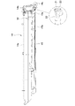
図2、図3および図4は、ジブ15を基端ブーム14aの底面に沿わせた下抱き位置に配置した状態の左側面図、右側面図および平面図である。後述のごとく、ジブ張出/格納作業においては、ジブ15を下抱き位置に配置した状態で、ブーム先端部14cとジブ基端部15aとの連結/解除を行う。
(Jib connection structure)
Next, the jib connection structure will be described.
2, 3 and 4 are a left side view, a right side view and a plan view of the state where the
図4に示すように、ジブ15を下抱き位置に配置した状態では、ジブ基端部15aはブーム先端部14cに位置し、ジブ15の先端部はブーム14の側方に位置したオフセット配置となっている。なお、ジブ15の先端部はブーム14に対して運転室13の反対側に位置している。以下、オフセット配置においてジブ15の先端部が位置する側を左側、その反対側(運転室13側)を右側と称する。ただし、左右が逆の実施形態としてもよい。
As shown in FIG. 4, in a state where the
ブーム先端部14cには、その両側方に水平に張り出したジブ連結軸21、21が設けられている。また、図2および図3に示すように、二股形状のジブ基端部15aの各端部にはジブ基端係合部22、22が設けられている。
The boom
ジブ基端係合部22はU字形状に形成されており、ジブ連結軸21を嵌め込み可能となっている。また、ジブ基端係合部22の先端部には差込孔が形成されている。ジブ基端係合部22にジブ連結軸21を嵌め込み、差込孔にピン23を差し込むことで、ジブ連結軸21が抜け止めされる。これにより、ジブ基端係合部22とジブ連結軸21とを連結できる。
The jib base
(ジブ張出格納機構)
つぎに、本実施形態のジブ張出格納機構を説明する。
本実施形態のジブ張出格納機構は、上記の様な移動式クレーンCにおいて、ブーム14に対してジブ15を張出/格納するための機構である。ジブ張出格納機構は、ガイド部材30、第1ジブ支持部材40、第2ジブ支持部材50からなる。ガイド部材30はブーム14の右側に設けられている。第1ジブ支持部材40および第2ジブ支持部材50はブーム14の左側に設けられている。以下、各部材を順に説明する。
(Jib overhanging storage mechanism)
Next, the jib overhanging storage mechanism of this embodiment will be described.
The jib overhanging storage mechanism of the present embodiment is a mechanism for overhanging / housing the
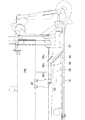
(ガイド部材30)
ガイド部材30は、ジブ張出/格納作業において、ブーム14の伸縮にともない、ジブ15の姿勢を案内するための部材である。図5に示すように、ガイド部材30は、ガイドローラ31と、ガイドローラ31を案内するガイド32とからなる。
(Guide member 30)
The
ジブ15の基端部側面には、底面側に突出したアーム33が設けられている。ガイドローラ31はアーム33の先端部に回転自在に設けられている。なお、図5において、ジブ15はその底面を基端ブーム14aに向けた状態で配置されている。
On the side surface of the base end portion of the
ガイド32は、基端ブーム14aの先端部側面に、底面側に突出した状態で設けられている。ガイド32は、第1軌道部材34、第2軌道部材35、および補正プレート36を有している。図5における一点鎖線は、ガイド32を構成する側壁37を示す。側壁37は、第1軌道部材34および第2軌道部材35を支持するともに、ガイドローラ31の横方向(紙面に対して垂直な方向)の動きを規制する機能を有する。説明の便宜のため、側壁37はその外形のみを一点鎖線で示す。
The
第1軌道部材34の表面を第1軌道面34s、第2軌道部材35の表面を第2軌道面35s、補正プレート36の表面を第3軌道面36sと称する。これら軌道面34s、35s、36sをガイドローラ31が転動することで、ジブ15が案内される。
The surface of the
第1軌道面34sは、ブーム14の先端から基端に向かってブーム14の底面から上面に向かう傾斜を有する。そのため、後述のごとく、ジブ張出作業において、ブーム14の伸長にともないガイドローラ31が第1軌道面34sを転動することで、ジブ15が基端ブーム14aの底面から引き離される。また、ジブ格納作業において、ブーム14の収縮にともないガイドローラ31が第1軌道面34sを転動することで、ジブ15が基端ブーム14aの底面に引き寄せられる。
The
第2軌道面35sは、ブーム14の中心軸と平行であり、第1軌道面34sの基端側端部と接続している。そのため、後述のごとく、ジブ張出/格納作業において、ブーム14の伸縮にともないガイドローラ31が第2軌道面35sを転動することで、ジブ15が基端ブーム14aの底面に引き寄せられた状態で、基端ブーム14aに沿って移動する。
The
第3軌道面36sは、第2軌道面35sから突出した凸形である。そのため、後述のごとく、ジブ張出/格納作業において、ブーム14の伸縮にともないガイドローラ31が第3軌道面36sを転動することで、ジブ15が基端ブーム14aの底面にさらに引き寄せられる。
The
本実施形態では第2軌道面35sに補正プレート36を載置する構成としたが、これに代えて、第2軌道部材35をプレス加工により屈曲させて、第2軌道面35sとともに第3軌道面36sを形成してもよい。ただし、補正プレート36を用いる方が、第2軌道面35sに補正プレート36を載置するだけなので、製造が容易である。また、プレス加工の場合よりも強度が高くなる。
In the present embodiment, the
本実施形態では、ガイドローラ31をジブ15に設け、ガイド32を基端ブーム14aに設けたが、これに代えて、ガイドローラ31を基端ブーム14aに設け、ガイド32をジブ15に設けてもよい。
In this embodiment, the
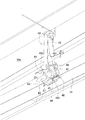
(第1ジブ支持部材40)
第1ジブ支持部材40は、格納状態のジブ15を支持するための部材である。また、第1ジブ支持部材40は、ジブ15をブーム14の側面に沿った格納位置と下抱き位置との間で回動させる機能を有する。
(First jib support member 40)
The first
図6に示すように、基端ブーム14aの略中央には底部側面にブラケット41が軸支されている。また、基端ブーム14aの上部側面とブラケット41との間には油圧シリンダ42が取り付けられている。油圧シリンダ42の伸縮によりブラケット41が基端ブーム14aに対して回動する。
As shown in FIG. 6, a
ブラケット41にはジブ固定ピン43が設けられている。ジブ固定ピン43は円柱形であり、その先端部が円錐状に形成されている。ジブ固定ピン43は、ブーム14の中心軸と平行であり、その先端部がブーム14の先端に向けて配置されている。なお、ジブ固定ピン43をジブ15の中心軸と平行に配置してもよい。
The
ブラケット41にはジブ固定ピン43の他に、2本の第1副ピン44、44が設けられている。第1副ピン44はジブ固定ピン43よりも小径短尺の円柱形であり、その先端部が円錐状に形成されている。第1副ピン44は、ブーム14の中心軸と平行であり、その先端部がブーム14の先端に向けて配置されている。なお、第1副ピン44をジブ15の中心軸と平行に配置してもよい。
In addition to the
ジブ15の略中央には底面にピン受け45が設けられている。なお、図6において、ジブ15はその底面を基端ブーム14aに向けた状態で配置されている。ピン受け45は前端リブ46および後端リブ47を有している。前端リブ46には前端差込孔48が形成されており、後端リブ47には後端差込孔49が形成されている。これら前端差込孔48および後端差込孔49にジブ固定ピン43を差し込み可能となっている。前端差込孔48および後端差込孔49は、ジブ15が基端ブーム14aの底面に引き寄せられた状態において、その中心軸がブーム14の中心軸と平行となるように配置されている。また、前端リブ46には第1副ピン44を差し込み可能な第1副差込孔46hが形成されている。なお、前端差込孔48および後端差込孔49を、その中心軸がジブ15の中心軸と平行となるように配置してもよい。
A
なお、前端差込孔48および後端差込孔49は特許請求の範囲に記載の「差込孔」に相当する。前端差込孔48は差込孔の前端開口部を構成し、後端差込孔49は差込孔の後端開口部を構成する。ここで、ジブ格納作業において、ジブ固定ピン43が先に差し込まれる方を「前端」とし、後に差し込まれる方を「後端」としている。
The front
前端差込孔48は縦長孔である。より詳細には、前端差込孔48は、ジブ15が基端ブーム14aの底面に引き寄せられた状態において、ブーム14の縦方向(底面から上面に向かう方向)に沿った縦長孔である。ジブ15が重量により撓むと、ピン受け45はジブ固定ピン43に対して下がる。また、ジブ固定ピン43およびピン受け45は、基端ブーム14aの側方に配置される。そのため、ジブ15の重量などにより先端ブーム14bが基端ブーム14aに対して回転すると、ピン受け45はジブ固定ピン43に対して下がる。要するに、ジブ15の撓みなどによりジブ固定ピン43とピン受け45は縦方向に位置がズレる。前端差込孔48はこのズレ方向に沿った長孔である。
The front
一方、後端差込孔49は丸孔であり、その内径はジブ固定ピン43の外径と略同一である。ここで、「略同一」には、後端差込孔49の内径がジブ固定ピン43の外径と同一の場合のほか、後端差込孔49の内径がジブ固定ピン43の外径よりも若干大きい場合も含まれる。なお、特許請求の範囲に記載の「内寸」には内径が含まれ、「外寸」には外径が含まれる。
On the other hand, the rear
前端差込孔48を縦長孔に形成するのに代えて、丸孔のまま内径をジブ固定ピン43の外径よりも大きくしてもよい。要するに、ジブ固定ピン43の中心軸が前端差込孔48の中心軸からズレていても、ジブ固定ピン43を前端差込孔48に差し込めるような余裕があればよい。
Instead of forming the front
ジブ固定ピン43は円柱形に限定されず角柱形でもよい。この場合、ジブ固定ピン43の先端部を角錐状に形成してもよい。また、前端差込孔48および後端差込孔49を角孔としてもよい。前端差込孔48の内寸をジブ固定ピン43の外寸よりも大きくし、後端差込孔49の内寸をジブ固定ピン43の外寸と略同一とすればよい。
The
ジブ固定ピン43の差込孔を、前端差込孔48および後端差込孔49からなる構成に代えて、単一の差込孔としてもよい。この場合、差込孔の前端開口部の内寸をジブ固定ピン43の外寸よりも大きくし、後端開口部の内寸をジブ固定ピン43の外寸と略同一とすればよい。前端開口部と後端開口部の間は連続的に接続された構成とすればよい。ここで、差込孔の両端の開口部のうち、ジブ格納作業において、ジブ固定ピン43が差し込まれる方を「前端開口部」とし、ジブ固定ピン43の先端が突き出る方を「後端開口部」としている。
Instead of the configuration including the front
本実施形態では、ジブ固定ピン43を基端ブーム14aに設け、ピン受け45をジブ15に設けたが、これに代えて、ジブ固定ピン43をジブ15に設け、ピン受け45を基端ブーム14aに設けてもよい。
In this embodiment, the
(第2ジブ支持部材50)
第2ジブ支持部材50は、格納状態のジブ15を支持するための部材である。図7に示すように、基端ブーム14aの基端部には底面側部にアーム51が設けられている。アーム51の先端部に第2副ピン52が設けられている。第2副ピン52は小径短尺の円柱形であり、その先端部が円錐状に形成されている。第2副ピン52は、ブーム14の中心軸と平行であり、その先端部がブーム14の先端に向けて配置されている。
(Second jib support member 50)
The second
ジブ15の先端部には底面に第2ピン受け53が設けられている。なお、図7において、ジブ15はその底面を基端ブーム14aに向けた状態で配置されている。第2ピン受け53はリブ54を有している。リブ54には第2副ピン52を差し込み可能な第2副差込孔54hが形成されている。
A
(ジブ格納作業)
つぎに、ジブ格納作業を説明する。
(1)図8に示すように、ジブ15を張り出した状態では、ジブ15がブーム14に対してほぼ一直線状となっている。
(Jib storage work)
Next, the jib storage work will be described.
(1) As shown in FIG. 8, the
(2)ジブ15にはチルトシリンダ15cが搭載されている。チルトシリンダ15cのロッドはテンションロッド15bに連結されている。チルトシリンダ15cを収縮させて、テンションロッド15bの張力を緩める。そうすると、図9(I)に示すように、ジブ15はジブ連結軸21を中心として前方に回転し、ブーム先端部14cから吊り下げられた状態となる。
(2) A
(3)図9(I)に示す工程では、ブーム14を起仰させ、起伏角度を適切な角度に調整し、ブーム14を僅かに伸長させている。この状態からブーム14を収縮させると、ガイドローラ31がガイド32に案内され、これによりジブ15が基端ブーム14aの底面に引き寄せられる(図9(II))。ブーム14をさらに収縮させると、ジブ15が基端ブーム14aに沿って移動し、第1ジブ支持部材40および第2ジブ支持部材50が連結される(図9(III))。
(3) In the step shown in FIG. 9 (I), the
(4)つぎに、ブーム14を倒伏させる。つぎに、ジブ基端係合部22の差込孔からピン23を抜き取り、ジブ基端係合部22とジブ連結軸21との連結を解除する(図2および図3参照)。そうすると、ジブ15は第1ジブ支持部材40と第2ジブ支持部材50とによって支持された状態となる。
(4) Next, the
(5)最後に、第1ジブ支持部材40の油圧シリンダ42を収縮させることで、ジブ15を下抱き位置から格納位置に回動させる。そうすると、図1に示すように、ジブ15はブーム14の側面に沿って格納される。
(5) Finally, the
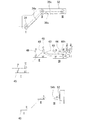
つぎに、図10に基づき、上記ジブ格納作業における工程(3)を、ガイド部材30、第1ジブ支持部材40、第2ジブ支持部材50に注目して詳説する。なお、図10におけるI、II、IIIは、各段階におけるガイドローラ31、ピン受け45、および第2ピン受け53の位置を示している。また、図10における一点鎖線は、ガイドローラ31、ピン受け45、および第2ピン受け53の軌道を示している。図10のI、II、IIIの各段階は図9のI、II、IIIの各段階に対応する。
Next, the step (3) in the jib storing operation will be described in detail with reference to the
図10においてIは、ガイドローラ31がガイド32に導入された時の、ガイドローラ31のガイド32に対する位置、ピン受け45のジブ固定ピン43に対する位置、および第2ピン受け53の第2副ピン52に対する位置を示している。この状態からブーム14を収縮させると、それにともないガイドローラ31が第1軌道面34sを転動する。そうすると、ジブ15が基端ブーム14aの底面に引き寄せられる。
10, I indicates the position of the
前述のごとく、大型クレーンに搭載されるジブ15は、長尺であり、重量が重いため、撓みが大きい。また、大型クレーンは各部のガタが大きい。さらに、ラウンドブームは、先端ブーム14bが基端ブーム14aに対して回転しやすい。そのため、ガイドローラ31とガイド32によってジブ15を基端ブーム14aの底面に引き寄せても、ジブ固定ピン43と差込孔48、49との位置がズレてしまう。この問題を解決するため、ガイド32には第3軌道面36sが設けられている。
As described above, since the
図10においてIIは、ガイドローラ31が第3軌道面36sの頂部に達した時の、ガイドローラ31のガイド32に対する位置、ピン受け45のジブ固定ピン43に対する位置、および第2ピン受け53の第2副ピン52に対する位置を示している。第3軌道面36sは、第2軌道面35sから突出した凸形である。そのため、ガイドローラ31、ピン受け45、および第2ピン受け53の軌道は山なりとなる。
In FIG. 10, II represents the position of the
ガイドローラ31が第3軌道面36sを転動することで、ジブ15が基端ブーム14aの底面にさらに引き寄せられる。すなわち、ガイドローラ31が第3軌道面36sに位置する場合のジブ15の引き寄せ具合は、ガイドローラ31が第2軌道面35sに位置する場合に比べて大きい。これにより、ジブ15に撓みなどが生じてもジブ固定ピン43と差込孔48、49との位置ズレを補正できる。そのため、ジブ固定ピン43を差込孔48、49に差し込むことができる。
As the
ここで、ブーム14の収縮にともない、ジブ固定ピン43先端部の頂点が前端差込孔48を通過する前後において、ガイドローラ31が第3軌道面36sを通過する。換言すれば、第3軌道面36sは前記条件を満たす位置に配置されている。本実施形態では、第3軌道面36sを第1軌道面34sと第2軌道面35sの間に配置しているが、これに限定されない。例えば、前記条件を満たす限りにおいて、第3軌道面36sを第2軌道面35sの中間位置に設けてもよい。
Here, as the
ジブ固定ピン43先端部の頂点が前端差込孔48に到達する直前で、ピン受け45が持ち上げられ、ジブ固定ピン43と前端差込孔48との位置ズレが補正される。そのため、ジブ固定ピン43と前端リブ46が干渉することなく、ジブ固定ピン43を前端差込孔48に差し込むことができる。
Immediately before the apex of the tip of the
また、前端差込孔48は縦長孔である。これによっても、ジブ固定ピン43と前端差込孔48との位置ズレを吸収できる。そのため、ジブ固定ピン43と前端リブ46が干渉することなく、ジブ固定ピン43を前端差込孔48に差し込むことができる。
The front
さらにブーム14を収縮させると、それにともないガイドローラ31が第2軌道面を転動する。そうすると、ジブ15が基端ブーム14aの底面に引き寄せられた状態で、基端ブーム14aに沿って移動する。この際、ジブ15の引き寄せ具合は、ジブ15に撓みなどがない場合に、ジブ固定ピン43の中心軸と差込孔48、49の中心軸が略一致するよう設定されている。
When the
このように、ジブ固定ピン43先端部の頂点が前端差込孔48を通過した直後に、ジブ15の引き寄せ具合が通常の状態に戻される。そのため、ジブ15の撓み量の大小によらず、ジブ固定ピン43と差込孔48、49との位置調整ができる。また、ジブ固定ピン43とピン受け45が干渉して、過大な負荷がかかることを防止できる。
Thus, immediately after the apex of the tip of the
ブーム14の収縮にともない、まずジブ固定ピン43の先端部が前端差込孔48を通過する。これにより、ピン受け45が粗く位置決めされる。つぎにジブ固定ピン43が後端差込孔49に挿入される。後端差込孔49の内径はジブ固定ピン43の外径と略同一である。そのため、ジブ固定ピン43が後端差込孔49に完全に差し込まれた状態では、ジブ固定ピン43を位置決めできる。また、ジブ固定ピン43をピン受け45に対して固定できる。
As the
さらにブーム14を収縮させると、第1副ピン44が第1副差込孔46hに差し込まれる。ついで第2副ピン52が第2副差込孔54hに差し込まれる。このように、ジブ固定ピン43、第1副ピン44、第2副ピン52の順で、それぞれの差込孔に差し込まれる。図10においてIIIは、ジブ固定ピン43、第1副ピン44、および第2副ピン52がそれぞれの差込孔に完全に差し込まれた時の位置を示す。以上により、第1ジブ支持部材40および第2ジブ支持部材50が連結される
When the
(ジブ張出作業)
ジブ張出作業はジブ格納作業と逆の手順で行われる。ジブ張出作業においては、ジブ15を下抱き位置に配置してジブ基端係合部22とジブ連結軸21とを連結した後、ブーム14を起仰させ、起伏角度を適切な角度に調整する(図9(III))。
(Jib overhanging work)
The jib overhanging operation is performed in the reverse procedure of the jib storage operation. In the jib overhanging operation, the
つぎに、ブーム14を伸長させると、それにともない第2副ピン52、第1副ピン44、ジブ固定ピン43の順で、それぞれの差込孔からに抜き出される。これにより、第1ジブ支持部材40および第2ジブ支持部材50の連結が解除される(図9(II))。さらにブーム14を伸長させると、ガイドローラ31が第1軌道面34sを転動し、ジブ15が基端ブーム14aの底面からゆっくりと引き離される(図9(I))。
Next, when the
その後、チルトシリンダ15cを伸長させるとテンションロッド15bに張力を発生させることができ、ジブ連結軸21を中心としてジブ15を前方に張り出すことができる(図8参照)。
Thereafter, when the
14 ブーム
14a 基端ブーム
15 ジブ
30 ガイド部材
31 ガイドローラ
32 ガイド
34s 第1軌道面
35s 第2軌道面
36s 第3軌道面
40 第1ジブ支持部材
43 ジブ固定ピン
45 ピン受け
48 前端差込孔
49 後端差込孔
50 第2ジブ支持部材
14
Claims (4)
前記ジブまたは前記基端ブームに設けられたガイドローラと、
前記基端ブームまたは前記ジブに設けられ、前記ガイドローラを案内するガイドと、
前記基端ブームまたは前記ジブに設けられたジブ固定ピンと、
前記ジブまたは前記基端ブームに設けられ、前記ジブ固定ピンを差し込み可能な差込孔を有するピン受けと、を備え、
前記ガイドは、前記ガイドローラが転動する第1軌道面、第2軌道面、および第3軌道面を有し、
前記第1軌道面は、前記ブームの収縮にともない前記ガイドローラが転動することで、前記ジブが前記基端ブームの底面に引き寄せられる形状であり、
前記第2軌道面は、前記ブームの収縮にともない前記ガイドローラが転動することで、前記ジブが前記基端ブームの底面に引き寄せられた状態で該基端ブームに沿って移動する形状であり、
前記第3軌道面は、前記第2軌道面から突出した凸形である
ことを特徴とするジブ張出格納機構。 A jib overhanging storage mechanism for extending / retracting a jib over a boom having a proximal end boom,
A guide roller provided on the jib or the proximal boom;
A guide provided on the proximal boom or the jib for guiding the guide roller;
A jib fixing pin provided on the proximal boom or the jib;
A pin receiver provided on the jib or the base end boom and having an insertion hole into which the jib fixing pin can be inserted, and
The guide has a first raceway surface, a second raceway surface, and a third raceway surface on which the guide roller rolls,
The first track surface has a shape in which the jib is drawn to the bottom surface of the proximal boom by rolling the guide roller as the boom contracts,
The second raceway surface has a shape in which the guide roller rolls as the boom contracts, so that the jib moves along the proximal boom while being pulled toward the bottom surface of the proximal boom. ,
The jib overhanging storage mechanism, wherein the third raceway surface is a convex shape protruding from the second raceway surface.
前記第3軌道面の位置は、前記ブームの収縮にともない、前記ジブ固定ピン先端部の頂点が前記差込孔の前端開口部を通過する前後において、前記ガイドローラが通過する位置である
ことを特徴とする請求項1記載のジブ張出格納機構。 The jib fixing pin has a tip portion formed in a conical shape,
The position of the third raceway surface is a position where the guide roller passes before and after the apex of the tip of the jib fixing pin passes through the front end opening of the insertion hole as the boom contracts. The jib overhanging storage mechanism according to claim 1, wherein:
ことを特徴とする請求項1または2記載のジブ張出格納機構。 The jib overhanging storage mechanism according to claim 1 or 2, wherein the third raceway surface is a surface of a correction plate placed on the second raceway surface.
前記差込孔の後端開口部の内寸は、前記ジブ固定ピンの外寸と略同一である
ことを特徴とする請求項1、2または3記載のジブ張出格納機構。 The inner dimension of the front end opening of the insertion hole is larger than the outer dimension of the jib fixing pin,
The jib overhanging storage mechanism according to claim 1, 2, or 3, wherein an inner dimension of a rear end opening of the insertion hole is substantially the same as an outer dimension of the jib fixing pin.
Priority Applications (5)
| Application Number | Priority Date | Filing Date | Title |
|---|---|---|---|
| JP2015115020A JP6569311B2 (en) | 2015-06-05 | 2015-06-05 | Jib overhang storage mechanism |
| US15/570,773 US10287143B2 (en) | 2015-06-05 | 2016-02-01 | Overhanging storage mechanism for jib |
| PCT/JP2016/000478 WO2016194266A1 (en) | 2015-06-05 | 2016-02-01 | Overhanging storage mechanism for jib |
| CN201680028369.0A CN107614415B (en) | 2015-06-05 | 2016-02-01 | Cantilever stretches out accommodating mechanism |
| EP16802714.2A EP3305711B1 (en) | 2015-06-05 | 2016-02-01 | Overhanging storage mechanism for jib |
Applications Claiming Priority (1)
| Application Number | Priority Date | Filing Date | Title |
|---|---|---|---|
| JP2015115020A JP6569311B2 (en) | 2015-06-05 | 2015-06-05 | Jib overhang storage mechanism |
Publications (2)
| Publication Number | Publication Date |
|---|---|
| JP2017001776A true JP2017001776A (en) | 2017-01-05 |
| JP6569311B2 JP6569311B2 (en) | 2019-09-04 |
Family
ID=57442390
Family Applications (1)
| Application Number | Title | Priority Date | Filing Date |
|---|---|---|---|
| JP2015115020A Active JP6569311B2 (en) | 2015-06-05 | 2015-06-05 | Jib overhang storage mechanism |
Country Status (5)
| Country | Link |
|---|---|
| US (1) | US10287143B2 (en) |
| EP (1) | EP3305711B1 (en) |
| JP (1) | JP6569311B2 (en) |
| CN (1) | CN107614415B (en) |
| WO (1) | WO2016194266A1 (en) |
Families Citing this family (3)
| Publication number | Priority date | Publication date | Assignee | Title |
|---|---|---|---|---|
| US10589966B2 (en) * | 2017-03-02 | 2020-03-17 | Manitowoc Crane Companies, Llc | Jib coupling system for jib stowage |
| JP7375379B2 (en) * | 2019-08-29 | 2023-11-08 | コベルコ建機株式会社 | Auxiliary sheave device |
| CN113582051B (en) * | 2021-06-18 | 2023-03-03 | 中联重科股份有限公司 | Method for operating crane jib and crane |
Family Cites Families (17)
| Publication number | Priority date | Publication date | Assignee | Title |
|---|---|---|---|---|
| US3830376A (en) * | 1973-02-16 | 1974-08-20 | Harnischfeger Corp | Telescopic jib and bearing means therefor |
| JPS5131270U (en) * | 1974-08-30 | 1976-03-06 | ||
| US4222492A (en) * | 1978-01-05 | 1980-09-16 | Burro-Badger Corporation | Method for extending a boom assembly |
| US4595108A (en) * | 1982-01-26 | 1986-06-17 | Kabushiki Kaisha Kobe Seiko Sho | Method for stretching and folding extension jib in wheeled type crane |
| US4658972A (en) * | 1982-01-26 | 1987-04-21 | Kabushiki Kaisha Kobe Seiko Sho | Method for stretching and folding extension jib in wheeled type crane |
| US4483447A (en) * | 1982-05-26 | 1984-11-20 | Kidde, Inc. | Safety mounting for side stowable boom extension or jib |
| JPH0432397Y2 (en) * | 1986-09-02 | 1992-08-04 | ||
| JPH0726312Y2 (en) * | 1989-01-27 | 1995-06-14 | 株式会社神戸製鋼所 | Jib storage for wheeled crane |
| US4953724A (en) * | 1989-06-29 | 1990-09-04 | Kabushiki Kaisha Kobe Seiko Sho | Jib stretching and folding device |
| JPH0439296A (en) * | 1990-05-30 | 1992-02-10 | Kobe Steel Ltd | Crane jib overhanging and storing and its device |
| US5193698A (en) * | 1990-09-13 | 1993-03-16 | Kabushiki Kaisha Kobe Seiko Sho | Jib stretching and folding device for use in a crane |
| CA2157340C (en) * | 1994-09-27 | 1998-06-09 | Donald C. Hade, Jr. | Carrier track system for independent and/or synchronized operation of a multi-section telescopic boom structure |
| JP2000044173A (en) | 1998-07-29 | 2000-02-15 | Tadano Ltd | Jib projecting and storing device of movable crane |
| FI20055089A (en) * | 2005-02-23 | 2006-08-24 | Ponsse Oyj | Motion Crane |
| JP5248952B2 (en) * | 2008-08-29 | 2013-07-31 | 株式会社タダノ | Jib storage device for crane truck with jib |
| JP2010235250A (en) | 2009-03-31 | 2010-10-21 | Tadano Ltd | Structure of telescopic boom and crane |
| CN203021220U (en) * | 2012-12-26 | 2013-06-26 | 三一重工股份有限公司 | Subsidiary arm recovery device and crane |
-
2015
- 2015-06-05 JP JP2015115020A patent/JP6569311B2/en active Active
-
2016
- 2016-02-01 WO PCT/JP2016/000478 patent/WO2016194266A1/en active Application Filing
- 2016-02-01 US US15/570,773 patent/US10287143B2/en active Active
- 2016-02-01 CN CN201680028369.0A patent/CN107614415B/en active Active
- 2016-02-01 EP EP16802714.2A patent/EP3305711B1/en active Active
Also Published As
| Publication number | Publication date |
|---|---|
| JP6569311B2 (en) | 2019-09-04 |
| WO2016194266A1 (en) | 2016-12-08 |
| CN107614415B (en) | 2019-06-28 |
| EP3305711A1 (en) | 2018-04-11 |
| US20180118526A1 (en) | 2018-05-03 |
| EP3305711B1 (en) | 2023-04-12 |
| EP3305711A4 (en) | 2019-01-09 |
| US10287143B2 (en) | 2019-05-14 |
| CN107614415A (en) | 2018-01-19 |
Similar Documents
| Publication | Publication Date | Title |
|---|---|---|
| JP2008120525A (en) | Crane device with telescopic boom | |
| JP6569311B2 (en) | Jib overhang storage mechanism | |
| JP2006206233A5 (en) | ||
| JP2006206233A (en) | Telescopic boom horizontal deflection restricting device for travelling crane | |
| JP6578749B2 (en) | Jib overhang storage mechanism | |
| JP6531448B2 (en) | Jib connection structure | |
| JP5649870B2 (en) | Mobile crane | |
| JP5635331B2 (en) | Mobile crane | |
| JP6520270B2 (en) | Jib connection structure | |
| JP6151606B2 (en) | Counterweight position adjustment mechanism | |
| JP5454308B2 (en) | crane | |
| JP6388089B2 (en) | crane | |
| JP6620334B2 (en) | Boom deflection prevention device | |
| JP2012056750A (en) | Mobile crane | |
| JP3204446U (en) | Jib connection structure | |
| JP2012051692A (en) | Mobile crane | |
| JP6686570B2 (en) | Jib connection structure | |
| JP2018080011A (en) | Mobile crane | |
| JP4447362B2 (en) | Auxiliary jib device for wheel crane | |
| WO2016167027A1 (en) | Housing structure of tension rod | |
| WO2018052050A1 (en) | Crane | |
| JP2019001656A (en) | Gib retracting device and gib retracting method | |
| JP2020007139A (en) | Jack cylinder support device and jack-up method for working machine | |
| JPS6346464Y2 (en) | ||
| JP5352165B2 (en) | Jib overhang storage device for crane equipment |
Legal Events
| Date | Code | Title | Description |
|---|---|---|---|
| A621 | Written request for application examination |
Free format text: JAPANESE INTERMEDIATE CODE: A621 Effective date: 20180410 |
|
| A131 | Notification of reasons for refusal |
Free format text: JAPANESE INTERMEDIATE CODE: A131 Effective date: 20190423 |
|
| A521 | Request for written amendment filed |
Free format text: JAPANESE INTERMEDIATE CODE: A523 Effective date: 20190618 |
|
| TRDD | Decision of grant or rejection written | ||
| A01 | Written decision to grant a patent or to grant a registration (utility model) |
Free format text: JAPANESE INTERMEDIATE CODE: A01 Effective date: 20190709 |
|
| A61 | First payment of annual fees (during grant procedure) |
Free format text: JAPANESE INTERMEDIATE CODE: A61 Effective date: 20190722 |
|
| R150 | Certificate of patent or registration of utility model |
Ref document number: 6569311 Country of ref document: JP Free format text: JAPANESE INTERMEDIATE CODE: R150 |
|
| R250 | Receipt of annual fees |
Free format text: JAPANESE INTERMEDIATE CODE: R250 |
|
| R250 | Receipt of annual fees |
Free format text: JAPANESE INTERMEDIATE CODE: R250 |