JP2016516849A - Liquid leakage prevention masking material, masking tape and method for producing the same - Google Patents
Liquid leakage prevention masking material, masking tape and method for producing the same Download PDFInfo
- Publication number
- JP2016516849A JP2016516849A JP2016500824A JP2016500824A JP2016516849A JP 2016516849 A JP2016516849 A JP 2016516849A JP 2016500824 A JP2016500824 A JP 2016500824A JP 2016500824 A JP2016500824 A JP 2016500824A JP 2016516849 A JP2016516849 A JP 2016516849A
- Authority
- JP
- Japan
- Prior art keywords
- adhesive
- layer
- substrate
- base material
- masking
- Prior art date
- Legal status (The legal status is an assumption and is not a legal conclusion. Google has not performed a legal analysis and makes no representation as to the accuracy of the status listed.)
- Pending
Links
Images


Classifications
-
- C—CHEMISTRY; METALLURGY
- C09—DYES; PAINTS; POLISHES; NATURAL RESINS; ADHESIVES; COMPOSITIONS NOT OTHERWISE PROVIDED FOR; APPLICATIONS OF MATERIALS NOT OTHERWISE PROVIDED FOR
- C09J—ADHESIVES; NON-MECHANICAL ASPECTS OF ADHESIVE PROCESSES IN GENERAL; ADHESIVE PROCESSES NOT PROVIDED FOR ELSEWHERE; USE OF MATERIALS AS ADHESIVES
- C09J175/00—Adhesives based on polyureas or polyurethanes; Adhesives based on derivatives of such polymers
- C09J175/04—Polyurethanes
-
- B—PERFORMING OPERATIONS; TRANSPORTING
- B32—LAYERED PRODUCTS
- B32B—LAYERED PRODUCTS, i.e. PRODUCTS BUILT-UP OF STRATA OF FLAT OR NON-FLAT, e.g. CELLULAR OR HONEYCOMB, FORM
- B32B38/00—Ancillary operations in connection with laminating processes
- B32B38/0004—Cutting, tearing or severing, e.g. bursting; Cutter details
-
- B—PERFORMING OPERATIONS; TRANSPORTING
- B05—SPRAYING OR ATOMISING IN GENERAL; APPLYING FLUENT MATERIALS TO SURFACES, IN GENERAL
- B05B—SPRAYING APPARATUS; ATOMISING APPARATUS; NOZZLES
- B05B12/00—Arrangements for controlling delivery; Arrangements for controlling the spray area
- B05B12/16—Arrangements for controlling delivery; Arrangements for controlling the spray area for controlling the spray area
- B05B12/20—Masking elements, i.e. elements defining uncoated areas on an object to be coated
- B05B12/24—Masking elements, i.e. elements defining uncoated areas on an object to be coated made at least partly of flexible material, e.g. sheets of paper or fabric
-
- B—PERFORMING OPERATIONS; TRANSPORTING
- B05—SPRAYING OR ATOMISING IN GENERAL; APPLYING FLUENT MATERIALS TO SURFACES, IN GENERAL
- B05C—APPARATUS FOR APPLYING FLUENT MATERIALS TO SURFACES, IN GENERAL
- B05C21/00—Accessories or implements for use in connection with applying liquids or other fluent materials to surfaces, not provided for in groups B05C1/00 - B05C19/00
- B05C21/005—Masking devices
-
- B—PERFORMING OPERATIONS; TRANSPORTING
- B32—LAYERED PRODUCTS
- B32B—LAYERED PRODUCTS, i.e. PRODUCTS BUILT-UP OF STRATA OF FLAT OR NON-FLAT, e.g. CELLULAR OR HONEYCOMB, FORM
- B32B25/00—Layered products comprising a layer of natural or synthetic rubber
- B32B25/20—Layered products comprising a layer of natural or synthetic rubber comprising silicone rubber
-
- B—PERFORMING OPERATIONS; TRANSPORTING
- B32—LAYERED PRODUCTS
- B32B—LAYERED PRODUCTS, i.e. PRODUCTS BUILT-UP OF STRATA OF FLAT OR NON-FLAT, e.g. CELLULAR OR HONEYCOMB, FORM
- B32B27/00—Layered products comprising a layer of synthetic resin
- B32B27/30—Layered products comprising a layer of synthetic resin comprising vinyl (co)polymers; comprising acrylic (co)polymers
-
- B—PERFORMING OPERATIONS; TRANSPORTING
- B32—LAYERED PRODUCTS
- B32B—LAYERED PRODUCTS, i.e. PRODUCTS BUILT-UP OF STRATA OF FLAT OR NON-FLAT, e.g. CELLULAR OR HONEYCOMB, FORM
- B32B27/00—Layered products comprising a layer of synthetic resin
- B32B27/40—Layered products comprising a layer of synthetic resin comprising polyurethanes
-
- B—PERFORMING OPERATIONS; TRANSPORTING
- B32—LAYERED PRODUCTS
- B32B—LAYERED PRODUCTS, i.e. PRODUCTS BUILT-UP OF STRATA OF FLAT OR NON-FLAT, e.g. CELLULAR OR HONEYCOMB, FORM
- B32B37/00—Methods or apparatus for laminating, e.g. by curing or by ultrasonic bonding
- B32B37/12—Methods or apparatus for laminating, e.g. by curing or by ultrasonic bonding characterised by using adhesives
- B32B37/1284—Application of adhesive
- B32B37/1292—Application of adhesive selectively, e.g. in stripes, in patterns
-
- B—PERFORMING OPERATIONS; TRANSPORTING
- B32—LAYERED PRODUCTS
- B32B—LAYERED PRODUCTS, i.e. PRODUCTS BUILT-UP OF STRATA OF FLAT OR NON-FLAT, e.g. CELLULAR OR HONEYCOMB, FORM
- B32B43/00—Operations specially adapted for layered products and not otherwise provided for, e.g. repairing; Apparatus therefor
- B32B43/006—Delaminating
-
- B—PERFORMING OPERATIONS; TRANSPORTING
- B32—LAYERED PRODUCTS
- B32B—LAYERED PRODUCTS, i.e. PRODUCTS BUILT-UP OF STRATA OF FLAT OR NON-FLAT, e.g. CELLULAR OR HONEYCOMB, FORM
- B32B7/00—Layered products characterised by the relation between layers; Layered products characterised by the relative orientation of features between layers, or by the relative values of a measurable parameter between layers, i.e. products comprising layers having different physical, chemical or physicochemical properties; Layered products characterised by the interconnection of layers
- B32B7/04—Interconnection of layers
- B32B7/12—Interconnection of layers using interposed adhesives or interposed materials with bonding properties
-
- C—CHEMISTRY; METALLURGY
- C09—DYES; PAINTS; POLISHES; NATURAL RESINS; ADHESIVES; COMPOSITIONS NOT OTHERWISE PROVIDED FOR; APPLICATIONS OF MATERIALS NOT OTHERWISE PROVIDED FOR
- C09D—COATING COMPOSITIONS, e.g. PAINTS, VARNISHES OR LACQUERS; FILLING PASTES; CHEMICAL PAINT OR INK REMOVERS; INKS; CORRECTING FLUIDS; WOODSTAINS; PASTES OR SOLIDS FOR COLOURING OR PRINTING; USE OF MATERIALS THEREFOR
- C09D175/00—Coating compositions based on polyureas or polyurethanes; Coating compositions based on derivatives of such polymers
- C09D175/04—Polyurethanes
-
- C—CHEMISTRY; METALLURGY
- C09—DYES; PAINTS; POLISHES; NATURAL RESINS; ADHESIVES; COMPOSITIONS NOT OTHERWISE PROVIDED FOR; APPLICATIONS OF MATERIALS NOT OTHERWISE PROVIDED FOR
- C09J—ADHESIVES; NON-MECHANICAL ASPECTS OF ADHESIVE PROCESSES IN GENERAL; ADHESIVE PROCESSES NOT PROVIDED FOR ELSEWHERE; USE OF MATERIALS AS ADHESIVES
- C09J183/00—Adhesives based on macromolecular compounds obtained by reactions forming in the main chain of the macromolecule a linkage containing silicon, with or without sulfur, nitrogen, oxygen, or carbon only; Adhesives based on derivatives of such polymers
- C09J183/16—Adhesives based on macromolecular compounds obtained by reactions forming in the main chain of the macromolecule a linkage containing silicon, with or without sulfur, nitrogen, oxygen, or carbon only; Adhesives based on derivatives of such polymers in which all the silicon atoms are connected by linkages other than oxygen atoms
-
- C—CHEMISTRY; METALLURGY
- C09—DYES; PAINTS; POLISHES; NATURAL RESINS; ADHESIVES; COMPOSITIONS NOT OTHERWISE PROVIDED FOR; APPLICATIONS OF MATERIALS NOT OTHERWISE PROVIDED FOR
- C09J—ADHESIVES; NON-MECHANICAL ASPECTS OF ADHESIVE PROCESSES IN GENERAL; ADHESIVE PROCESSES NOT PROVIDED FOR ELSEWHERE; USE OF MATERIALS AS ADHESIVES
- C09J7/00—Adhesives in the form of films or foils
- C09J7/30—Adhesives in the form of films or foils characterised by the adhesive composition
- C09J7/38—Pressure-sensitive adhesives [PSA]
-
- B—PERFORMING OPERATIONS; TRANSPORTING
- B32—LAYERED PRODUCTS
- B32B—LAYERED PRODUCTS, i.e. PRODUCTS BUILT-UP OF STRATA OF FLAT OR NON-FLAT, e.g. CELLULAR OR HONEYCOMB, FORM
- B32B2607/00—Walls, panels
-
- C—CHEMISTRY; METALLURGY
- C09—DYES; PAINTS; POLISHES; NATURAL RESINS; ADHESIVES; COMPOSITIONS NOT OTHERWISE PROVIDED FOR; APPLICATIONS OF MATERIALS NOT OTHERWISE PROVIDED FOR
- C09J—ADHESIVES; NON-MECHANICAL ASPECTS OF ADHESIVE PROCESSES IN GENERAL; ADHESIVE PROCESSES NOT PROVIDED FOR ELSEWHERE; USE OF MATERIALS AS ADHESIVES
- C09J2203/00—Applications of adhesives in processes or use of adhesives in the form of films or foils
- C09J2203/31—Applications of adhesives in processes or use of adhesives in the form of films or foils as a masking tape for painting
-
- Y—GENERAL TAGGING OF NEW TECHNOLOGICAL DEVELOPMENTS; GENERAL TAGGING OF CROSS-SECTIONAL TECHNOLOGIES SPANNING OVER SEVERAL SECTIONS OF THE IPC; TECHNICAL SUBJECTS COVERED BY FORMER USPC CROSS-REFERENCE ART COLLECTIONS [XRACs] AND DIGESTS
- Y10—TECHNICAL SUBJECTS COVERED BY FORMER USPC
- Y10T—TECHNICAL SUBJECTS COVERED BY FORMER US CLASSIFICATION
- Y10T156/00—Adhesive bonding and miscellaneous chemical manufacture
- Y10T156/11—Methods of delaminating, per se; i.e., separating at bonding face
-
- Y—GENERAL TAGGING OF NEW TECHNOLOGICAL DEVELOPMENTS; GENERAL TAGGING OF CROSS-SECTIONAL TECHNOLOGIES SPANNING OVER SEVERAL SECTIONS OF THE IPC; TECHNICAL SUBJECTS COVERED BY FORMER USPC CROSS-REFERENCE ART COLLECTIONS [XRACs] AND DIGESTS
- Y10—TECHNICAL SUBJECTS COVERED BY FORMER USPC
- Y10T—TECHNICAL SUBJECTS COVERED BY FORMER US CLASSIFICATION
- Y10T428/00—Stock material or miscellaneous articles
- Y10T428/24—Structurally defined web or sheet [e.g., overall dimension, etc.]
- Y10T428/24777—Edge feature
-
- Y—GENERAL TAGGING OF NEW TECHNOLOGICAL DEVELOPMENTS; GENERAL TAGGING OF CROSS-SECTIONAL TECHNOLOGIES SPANNING OVER SEVERAL SECTIONS OF THE IPC; TECHNICAL SUBJECTS COVERED BY FORMER USPC CROSS-REFERENCE ART COLLECTIONS [XRACs] AND DIGESTS
- Y10—TECHNICAL SUBJECTS COVERED BY FORMER USPC
- Y10T—TECHNICAL SUBJECTS COVERED BY FORMER US CLASSIFICATION
- Y10T428/00—Stock material or miscellaneous articles
- Y10T428/24—Structurally defined web or sheet [e.g., overall dimension, etc.]
- Y10T428/24802—Discontinuous or differential coating, impregnation or bond [e.g., artwork, printing, retouched photograph, etc.]
-
- Y—GENERAL TAGGING OF NEW TECHNOLOGICAL DEVELOPMENTS; GENERAL TAGGING OF CROSS-SECTIONAL TECHNOLOGIES SPANNING OVER SEVERAL SECTIONS OF THE IPC; TECHNICAL SUBJECTS COVERED BY FORMER USPC CROSS-REFERENCE ART COLLECTIONS [XRACs] AND DIGESTS
- Y10—TECHNICAL SUBJECTS COVERED BY FORMER USPC
- Y10T—TECHNICAL SUBJECTS COVERED BY FORMER US CLASSIFICATION
- Y10T428/00—Stock material or miscellaneous articles
- Y10T428/24—Structurally defined web or sheet [e.g., overall dimension, etc.]
- Y10T428/24942—Structurally defined web or sheet [e.g., overall dimension, etc.] including components having same physical characteristic in differing degree
- Y10T428/2495—Thickness [relative or absolute]
- Y10T428/24959—Thickness [relative or absolute] of adhesive layers
-
- Y—GENERAL TAGGING OF NEW TECHNOLOGICAL DEVELOPMENTS; GENERAL TAGGING OF CROSS-SECTIONAL TECHNOLOGIES SPANNING OVER SEVERAL SECTIONS OF THE IPC; TECHNICAL SUBJECTS COVERED BY FORMER USPC CROSS-REFERENCE ART COLLECTIONS [XRACs] AND DIGESTS
- Y10—TECHNICAL SUBJECTS COVERED BY FORMER USPC
- Y10T—TECHNICAL SUBJECTS COVERED BY FORMER US CLASSIFICATION
- Y10T428/00—Stock material or miscellaneous articles
- Y10T428/26—Web or sheet containing structurally defined element or component, the element or component having a specified physical dimension
-
- Y—GENERAL TAGGING OF NEW TECHNOLOGICAL DEVELOPMENTS; GENERAL TAGGING OF CROSS-SECTIONAL TECHNOLOGIES SPANNING OVER SEVERAL SECTIONS OF THE IPC; TECHNICAL SUBJECTS COVERED BY FORMER USPC CROSS-REFERENCE ART COLLECTIONS [XRACs] AND DIGESTS
- Y10—TECHNICAL SUBJECTS COVERED BY FORMER USPC
- Y10T—TECHNICAL SUBJECTS COVERED BY FORMER US CLASSIFICATION
- Y10T428/00—Stock material or miscellaneous articles
- Y10T428/28—Web or sheet containing structurally defined element or component and having an adhesive outermost layer
- Y10T428/2852—Adhesive compositions
- Y10T428/2878—Adhesive compositions including addition polymer from unsaturated monomer
- Y10T428/2891—Adhesive compositions including addition polymer from unsaturated monomer including addition polymer from alpha-beta unsaturated carboxylic acid [e.g., acrylic acid, methacrylic acid, etc.] Or derivative thereof
-
- Y—GENERAL TAGGING OF NEW TECHNOLOGICAL DEVELOPMENTS; GENERAL TAGGING OF CROSS-SECTIONAL TECHNOLOGIES SPANNING OVER SEVERAL SECTIONS OF THE IPC; TECHNICAL SUBJECTS COVERED BY FORMER USPC CROSS-REFERENCE ART COLLECTIONS [XRACs] AND DIGESTS
- Y10—TECHNICAL SUBJECTS COVERED BY FORMER USPC
- Y10T—TECHNICAL SUBJECTS COVERED BY FORMER US CLASSIFICATION
- Y10T428/00—Stock material or miscellaneous articles
- Y10T428/28—Web or sheet containing structurally defined element or component and having an adhesive outermost layer
- Y10T428/2852—Adhesive compositions
- Y10T428/2896—Adhesive compositions including nitrogen containing condensation polymer [e.g., polyurethane, polyisocyanate, etc.]
-
- Y—GENERAL TAGGING OF NEW TECHNOLOGICAL DEVELOPMENTS; GENERAL TAGGING OF CROSS-SECTIONAL TECHNOLOGIES SPANNING OVER SEVERAL SECTIONS OF THE IPC; TECHNICAL SUBJECTS COVERED BY FORMER USPC CROSS-REFERENCE ART COLLECTIONS [XRACs] AND DIGESTS
- Y10—TECHNICAL SUBJECTS COVERED BY FORMER USPC
- Y10T—TECHNICAL SUBJECTS COVERED BY FORMER US CLASSIFICATION
- Y10T428/00—Stock material or miscellaneous articles
- Y10T428/31504—Composite [nonstructural laminate]
- Y10T428/31551—Of polyamidoester [polyurethane, polyisocyanate, polycarbamate, etc.]
-
- Y—GENERAL TAGGING OF NEW TECHNOLOGICAL DEVELOPMENTS; GENERAL TAGGING OF CROSS-SECTIONAL TECHNOLOGIES SPANNING OVER SEVERAL SECTIONS OF THE IPC; TECHNICAL SUBJECTS COVERED BY FORMER USPC CROSS-REFERENCE ART COLLECTIONS [XRACs] AND DIGESTS
- Y10—TECHNICAL SUBJECTS COVERED BY FORMER USPC
- Y10T—TECHNICAL SUBJECTS COVERED BY FORMER US CLASSIFICATION
- Y10T428/00—Stock material or miscellaneous articles
- Y10T428/31504—Composite [nonstructural laminate]
- Y10T428/31652—Of asbestos
- Y10T428/31663—As siloxane, silicone or silane
Abstract
マスキング材と、基材とこの基材上に形成した接着剤層とを有するマスキングテープの製造方法。上記接着剤層はその厚さが好ましくは基板の厚さより厚く、上記接着剤層は上記マスキング材が設けられる表面の不連続部分に合致できる粘弾性係数を有する。好ましくは上記接着剤は、上記基材の横方向縁と一線をなす2列に形成し、上記マスキング材と上記表面の間に液漏れするのを防止せしめる。The manufacturing method of the masking tape which has a masking material, a base material, and the adhesive bond layer formed on this base material. The thickness of the adhesive layer is preferably greater than the thickness of the substrate, and the adhesive layer has a viscoelastic coefficient that can match a discontinuous portion of the surface on which the masking material is provided. Preferably, the adhesive is formed in two rows that are in line with the lateral edge of the substrate to prevent liquid leakage between the masking material and the surface.
Description
本発明は、接着用マスキング材、マスキングテープ特に、下側面に設けられ、この面からこれを損傷することなく除去でき、上記面に残った接着剤を除去する必要がなく、上記面とマスキング材間に液体が浸入するのを防止できるマスキング材に関するものである。 The present invention provides an adhesive masking material and a masking tape, in particular, provided on the lower surface, which can be removed without damaging the surface, and it is not necessary to remove the adhesive remaining on the surface. The present invention relates to a masking material that can prevent liquid from entering between.
接着用テープは、基材の少くとも一方の側に接着される接着剤層を有する紙、プラスチックまたは布等の可燃性材から成る。この接着剤層は基材の一側の全面をカバーするか、または長さの方向の一縁のみに沿って配置される。塗料等の液体から表面の対応する部分を保護しまたはマスクするためのマスキングテープは、マスキング材に関連する部分に汚れのない縁を作るために好ましい。 The adhesive tape is made of a combustible material such as paper, plastic or cloth having an adhesive layer bonded to at least one side of the substrate. This adhesive layer covers the entire surface of one side of the substrate or is disposed along only one edge in the length direction. Masking tapes for protecting or masking corresponding parts of the surface from liquids such as paint are preferred to create a clean edge on the part associated with the masking material.
このようなマスキングテープは、基材の一方または双方の面を横切る極めて薄い均一な層として接着される接着剤を含む。基材が液体により濡れたときの劣化抵抗低下を防ぐため基材の一側に接着される接着剤と、接着剤支持基材が液体に接触するのを阻止するため基材の他側に設けられる耐液体材料またはプラスチック片とを有するマスキング材が作られている。米国特許第1,726,744号、第1,779,588号,第2,171,544号、第2,510,120号には、夫々可燃性基材の少くとも1つの縁部分に沿って接着剤の比較的薄い層が設けられたマスキング材が提案されている。米国特許第3,032,181号には、マスキング材をロール状に形成するとき接着を防止し、基材の隣接する層から接着剤を容易に除去できるようにするため、テープの1つまたは1つ以上の縁上に狭い幅の接着剤のバンドを設け、対応する被覆をテープの背部に設けることが提案されている。 Such masking tape includes an adhesive that is adhered as a very thin uniform layer across one or both sides of the substrate. Provided on the other side of the substrate to prevent the adhesive support substrate from coming into contact with the liquid, and an adhesive bonded to one side of the substrate to prevent deterioration resistance degradation when the substrate gets wet with liquid A masking material is made having a liquid-resistant material or plastic piece to be applied. U.S. Pat. Nos. 1,726,744, 1,779,588, 2,171,544, and 2,510,120 each along at least one edge portion of a combustible substrate. Masking materials having a relatively thin layer of adhesive have been proposed. U.S. Pat. No. 3,032,181 includes one of the tapes to prevent adhesion when the masking material is formed into a roll and allows easy removal of the adhesive from adjacent layers of the substrate. It has been proposed to provide a narrow band of adhesive on one or more edges and a corresponding coating on the back of the tape.
米国特許第6,828,008号には、基材に少くとも液体が吸収されることを防ぎ、マスキング材に液体が加えられるのを遅くするため基材の縁上に吸収層を設けることが提案されている。米国特許出願公開第2008/0318038A1号には液状物質がマスキング材に接着するのを防ぐため接着剤と反対の基材側に液体排除材の条片を設けたマスキング材が示されている。 U.S. Pat. No. 6,828,008 provides an absorbent layer on the edge of the substrate to prevent at least the liquid from being absorbed by the substrate and to slow the addition of liquid to the masking material. Proposed. US Patent Application Publication No. 2008 / 0318038A1 shows a masking material in which a strip of liquid exclusion material is provided on the side of the substrate opposite to the adhesive to prevent the liquid material from adhering to the masking material.
上記特許の多くは、マスキング材の下側面に液状物質が漏れるのを防止するための縁封じ能力及び縁ブロック技術を改良せしめ、対応する処理工程の後付加物の除去を容易とし、マスキング材の機能を維持するようにされている。上記特許の夫々では、マスキング材の縁に対する液状物質の付着に抵抗でき、マスキング材の裏側の適用面の一部に液状物質が浸入するのを阻止できるマスキング材を作るという長い間の問題を解決することを試みている。これら市販されているマスキング製品は、所定の製品には達していない。 Many of the above patents have improved edge sealing capabilities and edge block technology to prevent leakage of liquid material to the underside of the masking material, facilitating removal of adducts after the corresponding processing steps, It is designed to maintain functionality. Each of the above patents solves the long-standing problem of creating a masking material that can resist the attachment of the liquid material to the edge of the masking material and prevent the liquid material from entering the part of the application surface on the back side of the masking material. Trying to do. These commercially available masking products do not reach the predetermined products.
液体の浸入を阻止するためのマスキング材の効果は、マスクされる面の粗さに大きく依存し、面が滑らかでない場合には漏れが生じ、汚れのない鮮明な縁には漏れが生じない。上記液体の浸入は毛細管作用により生じ、重力のような外部力に抗して極めて狭い隙間内に液体が流れ込む。このような効果は、生物学や化学テストで用いられる細い管内、塗料用ブラシの毛間、紙等の多孔性材料内、液化炭素繊維のような非多孔性材料内、または細胞内の液体の上昇として見られる。このような毛細管作用は、面を取り囲む固体と液体間の分子間吸引力によって生ずる。漏洩通路が十分に短かい場合には、液体を割れ目やギャップ内に押し込むコンテナ作用と液体間の接着力と液体内の分子凝集力によって生ずる表面張力が組み合わされる。上記毛細管作用は、マスキング材と処理面間に小さな気泡が形成される多くのマスキング材料に想定される。 The effect of the masking material to prevent the ingress of liquid depends largely on the roughness of the masked surface. If the surface is not smooth, leakage will occur, and a clean, clean edge will not leak. The intrusion of the liquid is caused by a capillary action, and the liquid flows into a very narrow gap against an external force such as gravity. Such effects can be attributed to the presence of liquids in thin tubes used in biological and chemical tests, between bristle brushes for paint, in porous materials such as paper, in non-porous materials such as liquefied carbon fibers, or in cells. Seen as a rise. Such capillary action is caused by an intermolecular attractive force between the solid and the liquid surrounding the surface. When the leakage path is sufficiently short, the container action that pushes the liquid into the cracks and gaps, the adhesive force between the liquids, and the surface tension generated by the molecular cohesive force in the liquid are combined. The capillary action is envisioned in many masking materials where small bubbles are formed between the masking material and the treated surface.
上記マスキング材の多くは、これを平らな面に適用した場合には液漏れを防止できるが、塗装される面が総べて正確に平らであるとは限らない。特に、布張りの壁及び天井に対しては対応する面部分や塗装する隣接面を好ましくマスクする能力が大きく制限される。上記マスキング製品の欠点は、異なる液状物質間や着色された面間に境界線が形成されている場合や、ゆず肌の面や、漆喰で化粧した面等のラフな面をマスクする場合に生ずる。 Many of the above masking materials can prevent liquid leakage when applied to a flat surface, but the surfaces to be coated are not necessarily exactly flat. In particular, for upholstered walls and ceilings, the ability to preferably mask corresponding surface portions and adjacent surfaces to be painted is greatly limited. The disadvantages of the above masking products occur when borders are formed between different liquid substances or colored surfaces, or when masking rough surfaces such as the surface of yuzu skin or the surface made of plaster. .
上記特許のマスキング材は多くの会社によって作られており、これらの技術は、テープの縁の下に塗料が漏れるのを防ぐとされているが、このような主張の信頼性は、きれいで極めて滑らかな面以外には生じない。図7に示したように実際の適用に際しては上記信頼性はしばしば生じない。 The masking material of the above patent is made by many companies and these techniques are supposed to prevent the paint from leaking under the edge of the tape, but the reliability of such claims is clean and extremely It does not occur except for smooth surfaces. As shown in FIG. 7, in the actual application, the reliability is not often generated.
従って、液状物質のために必要な条件を満たし、マスキング材の対応する部分を下側の処理面から除去でき、マスキング材を下側の処理面の形に合致するよう変形でき、マスキング材の背面に対する液漏れを防ぐことができ、且つマスキング材の除去を効率良くなし得る、マスキング材を必要としている。 Therefore, the necessary conditions for the liquid substance can be met, the corresponding part of the masking material can be removed from the lower processing surface, the masking material can be deformed to match the shape of the lower processing surface, and the back surface of the masking material Therefore, there is a need for a masking material that can prevent leakage of the liquid and efficiently remove the masking material.
本発明のマスキング材は上記の欠点の1つまたは1つ以上を解決したものである。本発明は、基材と、この基材に固定した接着剤層とを有するマスキングテープ及びその製造方法に関するものである。上記接着剤層は好ましくは厚さが少くとも0.003インチであり、接着剤層を細長くし、マスキング材を設ける面に関連した不連続形状に合致するよう変形できるタック(tack)量に比例した弾性率を有する材料によって形成する。好ましくは、接着剤層を、基材の長さ方向の縁に沿った幅の狭い2列のものとし、マスク面に接する接着剤の効果的な面積を減じ、この結果、マスク面に対する接着剤の単位圧力を増加し、マスキングテープとこれを設ける面間に液漏れが生じないようにする。 The masking material of the present invention overcomes one or more of the above disadvantages. The present invention relates to a masking tape having a base material and an adhesive layer fixed to the base material, and a method for producing the masking tape. The adhesive layer is preferably at least 0.003 inches thick and is proportional to the amount of tack that can be deformed to make the adhesive layer elongated and conform to the discontinuous shape associated with the masking surface. It is formed of a material having an elastic modulus. Preferably, the adhesive layer is of two narrow rows along the lengthwise edges of the substrate, reducing the effective area of the adhesive that contacts the mask surface, and consequently the adhesive to the mask surface. In order to prevent liquid leakage between the masking tape and the surface on which it is provided.
上記に基材と接着剤とを有する本発明のマスキングテープには上記特徴と1つまたは1つ以上を有せしめる。基材には上記基材の厚さに応じて互に分離した上面と底面と、2つの縁とを有せしめる。接着剤は上記基材の少くとも1つの縁に沿って上記底面に配置する。上記接着剤は、厚さが0.003インチ以上とし、基材の底面で外側方向に延ばし、塗装壁のように面に接触せしめたとき接着剤がその始めの厚さの1.25倍以上に弾性変形可能ならしめる。 The masking tape of the present invention having the substrate and the adhesive as described above has the above characteristics and one or more. The base material has a top surface and a bottom surface separated from each other according to the thickness of the base material, and two edges. Adhesive is placed on the bottom surface along at least one edge of the substrate. The adhesive has a thickness of 0.003 inches or more, extends outwardly at the bottom surface of the base material, and when the adhesive is brought into contact with the surface like a painted wall, the adhesive is 1.25 times or more of the initial thickness. To be elastically deformable.
上記基材層と接着剤層を含むテープアセンブリには、上記特徴の1つまたは1つ以上を有せしめる。上記基材層には基材の長さ方向に延びる対向面と対抗縁を有せしめ、上記対抗縁間の長さによって定められる基材層の長さ方向に交叉する方向に上記対向面が延びるようにする。上記接着剤層は上記基材層の少くとも1つの面に固定し、上記接着剤層の一縁が上記基材層の対向縁の少くとも1つに一線となるようにし、上記接着剤層の厚さを上記基材層の厚さ方向に一線をなす長さによって定め、上記基材層の厚さの少くとも1.5倍とする。 The tape assembly including the substrate layer and the adhesive layer may have one or more of the above features. The base material layer has a facing surface and a facing edge extending in the length direction of the base material, and the facing surface extends in a direction crossing the length direction of the base material layer determined by the length between the facing edges. Like that. The adhesive layer is fixed to at least one surface of the base material layer, and one edge of the adhesive layer is aligned with at least one opposite edge of the base material layer, and the adhesive layer Is determined by the length of a line in the thickness direction of the base material layer, and at least 1.5 times the thickness of the base material layer.
上記1つまたは1つ以上の特徴を有する本発明のマスキングテープ製造方法は、基材に対し接着剤の多数の列を設けることを含む。接着剤の多数の列が上記基材の隣接する層の間に入り込むように基材を巻くことによって、基材と接着剤の多数の列の細長いロールを形成せしめる。細長いロールを切断して細長いロールの直径と等しい最大直径の第1、第2ロールに分割せしめ、上記接着剤の多数の列の少くとも1つの列を分割した第1ロールの端部に関連する第1部分と、分割した第2ロールの端部に関連する第2部分を形成せしめる。 The masking tape manufacturing method of the present invention having one or more of the above features includes providing multiple rows of adhesive to the substrate. By rolling the substrate such that multiple rows of adhesive are interposed between adjacent layers of the substrate, an elongated roll of multiple rows of substrate and adhesive is formed. The elongated roll is cut and divided into first and second rolls having a maximum diameter equal to the diameter of the elongated roll, associated with the end of the first roll dividing at least one of the multiple rows of adhesive. A first portion and a second portion related to the end portion of the divided second roll are formed.
本発明の他の目的、特徴及び利益は以下の詳細な説明及び図面、本発明の好ましい実施例とその説明によって明らかならしめるが、本発明はこれに限定されることなく、本発明の範囲内で種々増減及び変形できることは勿論である。 Other objects, features and advantages of the present invention will become apparent from the following detailed description and drawings, preferred embodiments of the present invention and the description thereof, but the present invention is not limited thereto and is within the scope of the present invention. Of course, it can be variously increased and decreased and modified.
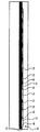
図1は本発明によるマスキングテープまたはマスキング材20の斜視図である。マスキング材20は基材22と、この基材22の面に設けた接着剤24とを有する。基材22は長さ26と、幅28と、厚さ30とを有する。また、基材22は第1面32と第2面34とを有する。第1、第2面32と34はマスキング材20の互に対向する作用面であり、一方の面は処理面となり、他方の面は大気に対向する面となる。基材22は長さ26と厚さ30を有する第1縁36と第2縁38とを有する。また、基材22は幅28と厚さ30によって定められる端面40を有する。基材22はプラスチック、布または紙等の可燃性材料で形成し、その厚さ30は約0.001インチ〜0.005インチとするのが好ましい。
FIG. 1 is a perspective view of a masking tape or masking
基材22は、上記のように布、プラスチックまたは紙を含む種々の材料により種々の形状とし、種々の目的に対応できるようにするのが好ましい。これらの目的の1つは、対向面からテープを容易に除去できるように選択された方法で切断または引き裂きできるようにすることである、そのため基材22の切断または引き裂き抵抗を一方の方向で他方の方向より大きくする。他の方法としては、基材22の製造プロセスにおいて、横方向または断面方向(CD)の一方向に基材22を容易に引き裂きでき、長さ方向(MD)の他方向で引き裂き抵抗を大きくすることである。
As described above, the
上記のように異なる方向で引き裂き抵抗が変るようにする材料の一例としては伸長可能なクラフト紙がある。 One example of a material that allows tear resistance to change in different directions as described above is stretchable kraft paper.
異なる方向で引き裂き抵抗が変るようにするには種々の方法がある。好ましくは、マスキング材20の断面方向の引き裂き抵抗をマスキング材20の長さ方向のそれより小さくし、断面方向には引き裂きが容易であるが、長さ方向では引き裂き困難となるようにし、この結果、マスキング材20または基材22を長さ方向で分離することなくマスキング材20または基材22を断面方向では手動で容易に対向面から除去できるようにする。
There are various ways to change the tear resistance in different directions. Preferably, the tear resistance in the cross-sectional direction of the masking
接着剤24は、少くとも1つの縁36または38の近くで少くとも1つの面32または34に設ける。好ましくは、後述するように接着剤24は異なるビーズ(beads)に区別し、対応するビーズが各縁36と38の近くに位置されるようにする。接着剤24には、基材22の第2面34に係合する第1の側面42と、これに対向する側面44とを有せしめる。また、接着剤24には、基材22の対応する第1縁36と第2縁38と一線をなす縁46を有せしめる。
図1に示すように、マスキング材20には接着剤24の第1列ビーズ48と接着剤24の第2列ビーズ50とを有せしめ、各列のビーズ48と50は基材22の長さ26方向に延ばす。好ましくは、第1列ビーズ48と第2列ビーズ50は夫々対応する基材22の端部に位置せしめ、各ビーズ48と50間には隙間54が形成されるようにする。上記2つの列ビーズ48と50は夫々基材22の第2面34に係合せしめるが、他の多数の列ビーズを隙間54間で基材22の第2面34に設けても良い。更に、基材22の第2面34の全面を接着剤24で覆っても良いがコストが増大する。好ましくは、基材の幅28の大きさに応じて隙間54には1列または1列以上の接着剤24を長さ26方向に設け、マスキング材20の使用の間基材22の変形を制限し、また、マスキング材20をロール状に巻いたときのマスキング材20の形状を均一に保ち得るようにする。
As shown in FIG. 1, the masking
各ビーズ48と50の形状は、夫々長さ56と幅58と厚さ60とによって定める。対応するビーズ48と50の長さ56の方向は、基材22の長さ26の方向と同一とし、ビーズ48と50の幅58の方向は、基材22の幅28の方向と同一とし、ビーズ48と50の厚さ60の方向は、基材22の厚さ30の方向と同一ならしめる。好ましい実施例においては、接着剤24の各ビーズ48と50の幅58は0.040インチと約0.200インチの間とし、厚さ60は約0.003インチ以上とし、より好ましくは約0.010インチと約0.100インチの間とする。ここで「約」とは接着剤の厚さの下限値のプラスマイナス0.007、上限値のプラスマイナス10%を意味する。好ましくは、接着剤24の幅58は接着剤24の厚さ60より大きくする。好ましくは、幅58と厚さ60の大きさは約3対1の比とする。本発明の好ましい実施例においては、接着剤24には約0.020〜0.040インチの厚さ60と、好ましくは約0.060〜0.120インチの幅58とを有せしめる。然しながら、マスキング材20の接着性と粘着性に対する要求を万足するならば、他の比率とすることができる。
The shape of each
図2はマスキング材20のロール66と、これに関連するコア64によって示されるロール形状の正面図である。接着剤24のビーズ48と50は基材22の互に隣接する層の間に配置する。即ち、ビーズ48と50の第1側面42を基材22の第2面34上に配置し、ビーズ48と50の対向側面44を、対応するロール66の隣接層に関連する基材22の第1面32に離脱可能に配置する。マスキング材20と対応する接着剤24のビーズ48と50とを下側の基材22の面から引きはがすことによってロール66からマスキング材20を取り出す。後述するように、基材22の第1面32が接着剤24に接着しないよう処理でき、且つマスキング材20の巻き取りを実行できる。また、マスキング材20はシートまたは条片状とし、多くの使用者が知っているロール状とはしないようにするのが好ましい。
FIG. 2 is a front view of the roll shape indicated by the
マスキング材20のビーズ48と50を形成する接着剤24は、少くともポリエチレンゲル接着剤と、シリコンゲル接着剤と、アクリル酸ゲル接着剤を含む群から選ぶか、他の型の接着剤を用いても良く、これらの特性は後述する。好ましくは、基材22と接着剤24は、マスキング材20によって覆われる、不規則な面または布を有する面に塗料のような液体が接触するのを防ぐ等の、マスキング材20の用法に関連する種々パラメータを万足するように選択する。
基材22の第1面32は、これから接着剤24を都合よく離すためシリコン皮膜等で処理し、マスキング材20の対応する層がロール66状に巻き得、且つ容易に巻きもどしできるようにする。基材22の第2面34は、これに接着剤24を分離不可能に接着できるように処理する。好ましくは、接着剤24はショア硬度で略20とする。
The adhesive 24 forming the
The
図3に示すように、接着剤24に後述する好ましい粘弾性特性を有せしめ、液漏れ阻止作用を対応する処理面72に有せしめるためコールドフロー(cold flowing)工程を加え接着剤24が平らでない処理面72に合致するようにする。図3は隣接するくぼみ74によって分離される多数のピーク70を含む処理面72に係合するマスキング材20の一部の平面図である。マスキング材20に当てられる処理面72の互に隣接するピーク70間の空洞またはくぼみ74を接着剤24によって埋めるようにし、マスキング材20が設けられる処理面72とマスキング材20間に、毛細管作用により生ずる液漏れを効果的阻止できるようにする。図3は、接着剤24の対応するビーズ48と50の対応する縁46と、基材22の対応する縁36の側面を示す。好ましくは、縁36と46は共通の面とする。接着剤24の粘弾性特性は接着剤24を処理面72の正しい形に順応せしめ、マスキング材20を処理面72から後に剥離するため基材22と接着剤24の相互接着機能は維持されるようにする。好ましくは接着剤24は多くの条件での液漏れを阻止する、市販で容易に入手できる接着剤は有しない物理的特性の独特な組み合わせを有し、通常の条件で示される大きな異なる表面エネルギーを有する表面から接着剤を除去できるようにする。
As shown in FIG. 3, the adhesive 24 is not flat by adding a cold flow process in order to provide the adhesive 24 with the preferable viscoelastic characteristics to be described later and to provide the corresponding treatment surface 72 with a liquid leakage prevention action. Match with the processing surface 72. FIG. 3 is a plan view of a portion of the masking
マスキング材20は、別々の表面粗さを有する種々の異なる処理面に協同できるものとするのが好ましい。即ち、“より平滑”であるが平面ではない面を処理する場合には、化粧塗りまたはノックダウン方式の生地処理のように、より大きい表面くぼみ部分を有する表面に対する場合に比べて接着剤24をより小さい厚さ60のビーズとする。種々の形のビーズを有するロールを作ることによって使用者は所望の用途に応じた厚さ60の接着剤24を有するマスキング製品を選択することができる。これによって特殊な課題のために必要な量だけの接着剤24を経済的に用いることができるようになる。
The masking
マスキング材20の意図された用途にかかわらず、基材22の第2面34と接着剤24間のタック(tack)と、基材22の第1面32と接着剤24間の分離可能なタック及び処理面72と接着剤24の対向側面44間の分離可能なタックに関連して図4A及び4Bに示す情報と表1に示されたパラメータを万足するよう接着剤24を構成する。
Regardless of the intended use of the masking
表1

図4Aと4Bは更に所望のタック及びまたは接着作用を得るための情報を示し、且つ処理面72と接着剤24の接触を維持するためのビーズの厚さ60の関数として種々の処理面に関連するピーク対ピーク面粗さの関数として処理面と所望の全接触係合を得てマスキング材20に対する液漏れを少くし、または阻止するための接着剤24の厚さ60を定める境界78を示す。
4A and 4B further provide information to obtain the desired tack and / or adhesion and relate to various processing surfaces as a function of
好ましくは、接着剤24は基材22から離れることなく処理面72のくぼみに接するよう、然しながら使用者の操作によって基材22の処理面から容易に全体を引き離し得る十分に柔軟なゲルタイプの材料とする。好ましくは、マスキング材20の端面40が裂けることを除いて使用中にマスキング材20が引きはがされる間基材22に対する接着剤24の結合が維持される形で基材22と接着剤24が互に協同するようにする。ここで用いる接着剤24のタックは面と接着剤の結合力の中間強さとし、接着剤は対応する結合力を長時間維持するようにする。即ち、タックの結合力は短時間であるが、接着剤の結合力は長時間維持されるようにする。接着剤24としては、接着力は小さいが所望のタックを得るものを選択するのが好ましい。テストにより、ある時間が経過した後でも処理面72に対する接着剤24の受け入れられる接着力の所望のタックパラメータをポリウレタンゲルが有することを示した。処理面72にあらかじめ施こした塗料の望ましくない引きはがし行程の間、処理面72に対し害を及ぼすことなく後のマスキング材の除去のため基材22の面34に対する接着剤24の相互作用を維持し、接着剤が前の形状に戻ることなく処理面72に対し完全に接触した状態を維持するような接着剤24を選択するのが好ましい。
Preferably, the adhesive 24 contacts the indentation of the processing surface 72 without leaving the
マスキング材20を用いるに際しては、マスキング材20を指または手のひらで加圧し、接着剤24を処理面72のピーク70とくぼみ74に接触せしめ、連続した相互作用を処理面72との間に形成せしめる。接着剤24は初めの形に戻すのが望ましいが、処理面72と接着剤24の相互作用に関連するタック以上にはならない剛性またはモジュラス(ひずみ対張力の比)が得られるような接着剤を選択し、縁36と46と処理面72に関連する境界全体に対して接触を維持できるようにする。マスキング材20に関連する図1に示す隙間54があれば、面34全体が接着剤24によって覆われている場合に面全体から除去するのに望まれる力の数分の一の力で処理面の下側からマスキング材20を容易に除去できるようになる。表面処理の間に1列の境界を形成する例を除いて、望ましい他の例においては接着剤24を基材22の縁36から縁38に延ばす。好ましい他の例においては、縁36と38の1つのみに接着剤24のビーズ48と50の1つを含める。接着剤24のビーズ48と50を両縁に形成すれば、均一なロール66を形成できるようになる利益がある。
In using the masking
表面多孔度が異なる種々のプローブを用いたとき、種々の異なる接着剤の利点を評価するため種々の細長い接着剤の接触タックが考慮された。このテストプロセスは、下塗りペンキ被覆プローブと、ブラシしたステンレススチールプローブ及びポリカーボネートプローブにより種々の接着剤を試すことを含む。対応する接着剤に接触せしめた後は、プローブを引き抜き、細長い接着剤を接着剤の初期の形に相対的に評価した。ここで示した1つまたは1つ以上の目的を達成するため、効果的な細長さとタックを有することが証明されたポリカーボネート材料に関連づけたとき、上記テストは細長い接着剤が少くとも25%の接触タックを有すると評価した。 When using different probes with different surface porosities, different elongate adhesive contact tacks were considered to evaluate the advantages of different adhesives. This test process involves testing various adhesives with a primed paint-coated probe and brushed stainless steel and polycarbonate probes. After contacting the corresponding adhesive, the probe was withdrawn and the elongated adhesive was evaluated relative to the initial shape of the adhesive. To achieve one or more of the objectives shown here, the above test shows that at least 25% of the elongate adhesive is in contact with a polycarbonate material that has been proven to have effective length and tack. Evaluated to have tack.
図5と図6は、マスキング材20の1つまたは1つ以上のロール66の作成方法説明図である。マスキング材20の細長いロール82は、矢印88によって示す長さ方向に沿って接着剤24の1つまたは1つ以上の細長いビーズ84と86を配置することによって形成する。ビーズ84と86は互に離して基材22の面34により支持し、互に隣接するビーズ84と86間に隙間90を形成する。ダイスまたは他の受け92は、対応するビーズ84と86間の基材22の面34に対してバルク源97から加える接着剤24に関連する入力94と複数の出力96を含む。バルク源97は、均一の接着剤24及びまたは接着剤24の形成に関連するパーツを受け取る形とものとするのが好ましい。
FIGS. 5 and 6 are explanatory views of a method for creating one or
図6に示すようにロール82は、基材22と接着剤24のビーズをロール82の切断またはスプリット機構99を通して所望の幅を有する個々のロール66に2分することができる。好ましくは、スプリット機構99は、第1、第2ローラ98と100間を通ったマスキング材20に協同し、各ビーズ84と86に関連する位置でロール82を2分し、各ビーズ84の対応する部分を第1ロール102及び第2ロール104に関連せしめ、各ビーズ86の対応する部分を第1ロール102及び第2ロール104に関連せしめる。また、各ビーズ84と86は、マスキング材20のロール66の対向する横方向縁に関連した対応するビーズ48と50に分離せしめる。スプリット機構99の操作により、対応するビーズ48と50に関連する縁46と、基材22に関連する縁36、38の夫々を基材22の面32と34に直交する平面状ならしめる。
As shown in FIG. 6, the
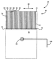
図7は、液漏れ抵抗を有するものとして宣伝された市販の種々のマスキング製品と比較した本発明のマスキング材20の性能説明図である。図7に示すように、処理面108は種々のマスキング材を施し、対応するマスキング製品の夫々に塗られたものと同様の塗料で仕上げられたものである。マスキング製品110、112、114及び116に関連して液漏れの種々の度合いが処理面の塗装部分118と、処理面108の塗装されないまたはマスクされた部分120間に明確に見られ、各製品110、112、114及び116は、サンプル面108のマスクされた区域とマスクされない区域間に所望の境界以下の変化を形成する。製品110、112、114及び116に関連する多くのマスキング材は、基材の一面全体に延びる接着剤層を有し、その厚さは0.0005インチから0.001インチの範囲である。
FIG. 7 is an illustration of the performance of the masking
図7に示すように、比較のため区域122と隣接する塗装部分118間の境界に関連して交互の横方向縁に直線境界124と126が形成されるようにマスキング材20を処理面108の区域122に設けた。接着剤24の厚さは0.003インチ、好ましくは約0.010インチから0.050インチ、または、公知のマスキング材の接着剤の厚さの略50倍とする。好ましくは、基材層の少くとも1つの面に固定した接着剤層は、接着剤層の一縁が基材層の少くとも1つの対向縁と一線をなし、接着剤層は基材層の厚さに等しい厚さを有し、且つ幅方向に直交し、接着剤層の幅と厚さの比が約2:1と約15:1の間となるようにする。例えば、厚さ0.010インチのビーズの幅は、約0.020インチと0.150インチの間とするのが好ましい。機能の面からみれば、ビーズは分離または切断手段に対応できる最小の幅であり、一方接着剤が連続する縁を維持できるようにする。切断プロセスを損なうことなく接着剤の機能を維持し、作成コストを減少するためにはビーズは約0.060インチより小さい幅とする。好ましくは、接着剤の幅と厚さは、処理面と約0.030インチシール係合することができる値とするのが好ましい。
As shown in FIG. 7, for comparison, the masking
区域122からマスキング材20を除去することによりマスキング材20の存在は消え、処理面108を汚すことは無かった。マスキング材20による液漏れ防止作用に関して他の種々の市販のマスキング材に比べてマスキング材20を塗装のために用いたときの利点は図7から明らかである。
By removing the masking
従って、マスキング材20は、基材とこの基材上に設けられ接着剤層を有するものであり、その厚さは好ましくは0.003インチ以上であり、マスキング材を設ける面に関連する不連続部分に適合できる弾力性を有する材料とする。好ましくは、接着剤は多数の列状とし、その少くとも1つの列は基材の横方向の縁と一線をなし、マスキング材とこれが設けられる面間に液体が浸透するのを防ぐものとする。マスキング材20は一時的であるが下側の面との間の相互作用を維持し、液漏れを防ぎ、下側の面からマスキング材全体を適切に除去でき、下側の面または仕上げ面を汚すことがない。
Accordingly, the masking
20 マスキング材またはマスキングテープ
22 基材
24 接着剤
26 長さ
28 幅
30 厚さ
32 第1面
34 第2面
36 第1縁
38 第2縁
40 端面
42 第1側面
44 対向側面
46 縁
48 第1列ビーズ
50 第2列ビーズ
54 隙間
56 長さ
58 幅
60 厚さ
64 コア
66 ロール
70 ピーク
72 処理面
74 くぼみ
78 境界
82 ロール
84 縁
86 縁
88 矢印
90 隙間
92 ダイスまたは受け
94 入力
96 出力
97 バルク源
98 第1ロール
99 スプリット機構
100 第2ロール
102 第1ロール
104 第2ロール
108 処理面
110 マスキング製品
112 マスキング製品
114 マスキング製品
116 マスキング製品
118 塗装部分
120 マスキング部分
122 区域
124 直線エリア境界
126 直線エリア境界
20 Masking material or masking
Claims (20)
上記基材層の少くとも1つの面に固定された接着剤層とより成り、
上記基材層の上記対向面と上記対向縁の夫々が上記基材層の長さ方向に延び、上記対向面が上記対向縁の長さによって定められる上記基材層の厚さの方向と交叉する方向に延び、上記接着剤層の一つの縁が上記基材層の対向縁の少くとも1つと一線をなし、上記接着剤層が上記基材の厚さ方向の厚さと、上記基材層の長さ方向と交叉する方向の幅とを有し、上記接着剤層の幅と厚さの比が約2:1と約15:1の間である、テープアセンブリ。 Base material layers having mutually facing surfaces and mutually facing edges;
An adhesive layer secured to at least one surface of the substrate layer,
Each of the facing surface and the facing edge of the base material layer extends in the length direction of the base material layer, and the facing surface intersects the direction of the thickness of the base material layer defined by the length of the facing edge. One edge of the adhesive layer is aligned with at least one opposing edge of the base material layer, and the adhesive layer has a thickness in the thickness direction of the base material and the base material layer. A tape assembly, wherein the ratio of width to thickness of the adhesive layer is between about 2: 1 and about 15: 1.
上記基材をロール状に巻いて細長いロールを形成し、上記複数列の接着剤が上記基材の互に隣接する層間に位置されるようにし、
上記細長いロールを切断して第1、第2ロールに分離せしめ、上記接着剤の複数列の少くとも1つの列を分離して第1ロールの端部に関連する第1部分と、第2ロールの端部に関連する第2部分を形成せしめるマスキングテープの製造方法。 Provide multiple rows of adhesive on the substrate,
The substrate is wound into a roll to form an elongated roll, and the plurality of rows of adhesives are positioned between adjacent layers of the substrate,
Cutting the elongate roll into first and second rolls, separating at least one of the plurality of rows of adhesive and separating a first portion associated with an end of the first roll; and a second roll The manufacturing method of the masking tape which forms the 2nd part relevant to the edge part of this.
The method of claim 17, wherein the plurality of rows of adhesive are formed by 0.010 inch thick beads.
Applications Claiming Priority (3)
| Application Number | Priority Date | Filing Date | Title |
|---|---|---|---|
| US13/834,151 | 2013-03-15 | ||
| US13/834,151 US8852729B1 (en) | 2013-03-15 | 2013-03-15 | Seep resistant masking material |
| PCT/US2014/021757 WO2014149992A1 (en) | 2013-03-15 | 2014-03-07 | Seep resistant masking material |
Publications (2)
| Publication Number | Publication Date |
|---|---|
| JP2016516849A true JP2016516849A (en) | 2016-06-09 |
| JP2016516849A5 JP2016516849A5 (en) | 2020-02-13 |
Family
ID=51528339
Family Applications (1)
| Application Number | Title | Priority Date | Filing Date |
|---|---|---|---|
| JP2016500824A Pending JP2016516849A (en) | 2013-03-15 | 2014-03-07 | Liquid leakage prevention masking material, masking tape and method for producing the same |
Country Status (9)
| Country | Link |
|---|---|
| US (3) | US8852729B1 (en) |
| EP (1) | EP2970720A4 (en) |
| JP (1) | JP2016516849A (en) |
| KR (1) | KR20160004269A (en) |
| CN (1) | CN105209564B (en) |
| BR (1) | BR112015023466A2 (en) |
| CA (1) | CA2906325A1 (en) |
| MX (1) | MX2015012895A (en) |
| WO (1) | WO2014149992A1 (en) |
Families Citing this family (3)
| Publication number | Priority date | Publication date | Assignee | Title |
|---|---|---|---|---|
| US20190070624A1 (en) * | 2017-09-07 | 2019-03-07 | Cliff Holt | Protective Floor Covering |
| US11872684B1 (en) * | 2020-09-01 | 2024-01-16 | Danielle Brewer | Gripping system and apparatus for attaching to a card |
| CN113275152B (en) * | 2021-04-12 | 2022-09-13 | 中建新疆建工(集团)有限公司 | Paint spraying mold and method for building baffle |
Citations (9)
| Publication number | Priority date | Publication date | Assignee | Title |
|---|---|---|---|---|
| JPS59149943U (en) * | 1983-03-25 | 1984-10-06 | 三協化学工業株式会社 | Protective adhesive tape for tires |
| JPS61135570U (en) * | 1985-02-12 | 1986-08-23 | ||
| US5640827A (en) * | 1996-01-31 | 1997-06-24 | Van Someren; Robert A. | Device and method for providing a barrier to unwanted penetration of finishing materials |
| US5776572A (en) * | 1997-01-24 | 1998-07-07 | Lipson; Ronald B. | Zone-coated masking material |
| JP2005524726A (en) * | 2002-05-03 | 2005-08-18 | ジオマスク インコーポレイテッド | Improved masking adhesive tape |
| JP2005539127A (en) * | 2002-09-18 | 2005-12-22 | スリーエム イノベイティブ プロパティズ カンパニー | Rough surface adhesive tape with thick consistent edges |
| JP3168098U (en) * | 2011-03-11 | 2011-06-02 | 翔吾 前川 | Masking tape material |
| JP2013018130A (en) * | 2011-07-07 | 2013-01-31 | Nippon Steel & Sumikin Drum Co Ltd | Masking sheet |
| JP2014519965A (en) * | 2011-03-11 | 2014-08-21 | ランゲマン マニュファクチュアリング リミテッド | Multilayer masking tape |
Family Cites Families (48)
| Publication number | Priority date | Publication date | Assignee | Title |
|---|---|---|---|---|
| US1779588A (en) | 1927-06-22 | 1930-10-28 | Doty John Omer | Masking strip |
| US1726744A (en) | 1927-10-26 | 1929-09-03 | Albert J Krug | Masking tape |
| US1869729A (en) * | 1930-02-19 | 1932-08-02 | Roscoe C Zuckerman | Adhesive tape container and cutter |
| US2171544A (en) | 1932-09-14 | 1939-09-05 | Minnesota Mining & Mfg | Masking strip |
| US2082546A (en) * | 1936-04-07 | 1937-06-01 | Machate Fred | Tape dispensing package |
| US2510120A (en) | 1946-05-31 | 1950-06-06 | Russell J Leander | Masking paper |
| US2699251A (en) * | 1952-06-25 | 1955-01-11 | Frank E Rizza | Dispenser for adhesive tape |
| US2790609A (en) * | 1953-04-22 | 1957-04-30 | Johnson & Johnson | Adhesive tape dispenser |
| US2975091A (en) * | 1955-07-21 | 1961-03-14 | Brady Co W H | Heat-resistant adhesive article |
| BE794492Q (en) | 1961-06-14 | 1973-05-16 | Daubert Chemical Co | MASKING SHEET |
| JPS54134187U (en) * | 1978-03-06 | 1979-09-18 | ||
| US4255469A (en) * | 1979-07-02 | 1981-03-10 | Hughes Aircraft Company | Process for selectively applying a conformal coating with a masking tape having an imbedded wire cutting edge |
| DE2934530A1 (en) * | 1979-08-27 | 1981-03-19 | Jürgen 4000 Düsseldorf Hanke | Paint masking foil of stretchable plastic - coated along edges with pressure sensitive adhesive |
| US4698051A (en) * | 1984-10-15 | 1987-10-06 | Jacobson Ralph S | Plastic bag opening device |
| SE8701245D0 (en) * | 1987-03-25 | 1987-03-25 | Intermall Ab | MASKING TAPE |
| US5240989A (en) * | 1987-12-11 | 1993-08-31 | Avery Dennison Corporation | Removable pressure-sensitive adhesive compositions comprising acrylic based emulsion polymers |
| US5154335A (en) * | 1990-09-14 | 1992-10-13 | Minnesota Mining And Manufacturing Company | Refillable dispenser for moist adhesive electrodes |
| US5133980A (en) * | 1990-10-15 | 1992-07-28 | Wm. Wrigley Jr. Company | Rolled tape-like confectionery product in a dispenser |
| FR2679916A1 (en) * | 1991-08-02 | 1993-02-05 | Du Pont | Ultrathin adhesive ribbon, roll of composite material for obtaining such an adhesive ribbon and processes for their production |
| US5294068A (en) * | 1991-09-26 | 1994-03-15 | Sensormatic Electronics Corporation | Dispenser for different width label rolls and method of using |
| CA2095555A1 (en) | 1992-12-16 | 1994-06-17 | Robert L. Popp | Apparatus and methods for selectively controlling a spray of liquid to form a distinct pattern |
| US5354614A (en) * | 1993-03-01 | 1994-10-11 | Minnesota Mining And Manufacturing Company | Masking tape with stiffened edge and method of gasket masking |
| US5464692A (en) * | 1993-06-17 | 1995-11-07 | Quality Manufacturing Incorporated | Flexible masking tape |
| US5468533A (en) | 1994-01-21 | 1995-11-21 | Kwik Paint Products | Masking material |
| WO1995029115A1 (en) | 1994-04-26 | 1995-11-02 | Minnesota Mining And Manufacturing Company | Splicing tape, splicing method and splice using the splicing tape |
| US5503487A (en) * | 1994-09-09 | 1996-04-02 | Ong; Bon S. | Custom index tabs |
| DE19502340C2 (en) | 1995-01-26 | 1998-04-23 | Guenter Klaus | Self-adhesive masking and sealing tape |
| US5698067A (en) * | 1996-01-02 | 1997-12-16 | Minnesotamining And Manufacturing Company | Protector for a roll of tape |
| US6185862B1 (en) * | 1997-04-02 | 2001-02-13 | David W. Nelson | Capturing device for insects |
| GB9913604D0 (en) | 1999-06-12 | 1999-08-11 | Jevtec Limited | Adhesive tapes |
| JP2001294821A (en) | 2000-04-11 | 2001-10-23 | Sekisui Chem Co Ltd | Pressure sensitive adhesive double coated tape |
| US6759110B1 (en) * | 2000-08-15 | 2004-07-06 | 3M Innovative Properties Company | Structured release liners with improved adhesion to adhesive articles |
| US6767629B2 (en) * | 2002-01-11 | 2004-07-27 | Kumud Shah | Pressure sensitive tape roll with intermediate divider |
| US20040126597A1 (en) * | 2002-12-27 | 2004-07-01 | Cohen Lewis S. | Facing for insulation and other applications |
| USD493838S1 (en) * | 2003-03-18 | 2004-08-03 | Kenichi Fujii | Adhesive tape |
| JP4610168B2 (en) * | 2003-08-06 | 2011-01-12 | スリーエム イノベイティブ プロパティズ カンパニー | Heat resistant masking tape |
| DE102004019908A1 (en) | 2004-04-21 | 2005-11-17 | Tesa Ag | Use of a double-sided adhesive foam adhesive tape for attaching structured flat cables, in particular on substrates such as the interior decorative parts of a car, in particular headliner, door side part, trunk lid |
| US20070062998A1 (en) * | 2005-09-19 | 2007-03-22 | Kanbar Maurice S | Note paper roll and dispensers |
| KR101100595B1 (en) * | 2006-10-31 | 2011-12-29 | 히다치 가세고교 가부시끼가이샤 | Adhesive tape and adhesive tape roll |
| US20080156444A1 (en) * | 2006-12-28 | 2008-07-03 | 3M Innovative Properties Company | Tape and Masking Material Composite |
| FR2914312A1 (en) | 2007-03-29 | 2008-10-03 | Didier Couvreur | Adhesive tape for masking parts such as car doors, comprises flexible support band provided on first face of first glue band and on opposed face of second glue band, where the support band comprises a band of flexible paper and foam |
| US20080318038A1 (en) | 2007-06-25 | 2008-12-25 | Dominick Joseph Fucito | Masking material with liquid-repellent surface |
| CA2665215C (en) | 2008-05-06 | 2015-01-06 | Intertape Polymer Corp. | Edge coatings for tapes |
| US8851284B2 (en) * | 2011-05-18 | 2014-10-07 | Thuban, Inc. | Adhesive bandage dispensing arrangements |
| CA2783917A1 (en) * | 2011-08-01 | 2013-02-01 | Nitto Denko Corporation | Roll body of band-like patch |
| US20130256909A1 (en) * | 2011-09-08 | 2013-10-03 | Dingying Xu | Patterned adhesive tape for backgrinding processes |
| WO2013066971A1 (en) * | 2011-10-31 | 2013-05-10 | Intertape Polymer Corp. | Pressure-chromic tape and methods of making same |
| US20140065377A1 (en) * | 2012-09-04 | 2014-03-06 | Berry Plastics Corporation | Abrasuib-resistant, hand-tearable adhesive tape |
-
2013
- 2013-03-15 US US13/834,151 patent/US8852729B1/en not_active Expired - Fee Related
-
2014
- 2014-03-07 WO PCT/US2014/021757 patent/WO2014149992A1/en active Application Filing
- 2014-03-07 BR BR112015023466A patent/BR112015023466A2/en not_active IP Right Cessation
- 2014-03-07 CA CA2906325A patent/CA2906325A1/en not_active Abandoned
- 2014-03-07 MX MX2015012895A patent/MX2015012895A/en unknown
- 2014-03-07 JP JP2016500824A patent/JP2016516849A/en active Pending
- 2014-03-07 CN CN201480016261.0A patent/CN105209564B/en not_active Expired - Fee Related
- 2014-03-07 KR KR1020157029456A patent/KR20160004269A/en not_active Application Discontinuation
- 2014-03-07 EP EP14767595.3A patent/EP2970720A4/en not_active Withdrawn
- 2014-08-01 US US14/449,224 patent/US20140338821A1/en not_active Abandoned
-
2015
- 2015-11-13 US US29/545,490 patent/USD790629S1/en active Active
Patent Citations (9)
| Publication number | Priority date | Publication date | Assignee | Title |
|---|---|---|---|---|
| JPS59149943U (en) * | 1983-03-25 | 1984-10-06 | 三協化学工業株式会社 | Protective adhesive tape for tires |
| JPS61135570U (en) * | 1985-02-12 | 1986-08-23 | ||
| US5640827A (en) * | 1996-01-31 | 1997-06-24 | Van Someren; Robert A. | Device and method for providing a barrier to unwanted penetration of finishing materials |
| US5776572A (en) * | 1997-01-24 | 1998-07-07 | Lipson; Ronald B. | Zone-coated masking material |
| JP2005524726A (en) * | 2002-05-03 | 2005-08-18 | ジオマスク インコーポレイテッド | Improved masking adhesive tape |
| JP2005539127A (en) * | 2002-09-18 | 2005-12-22 | スリーエム イノベイティブ プロパティズ カンパニー | Rough surface adhesive tape with thick consistent edges |
| JP3168098U (en) * | 2011-03-11 | 2011-06-02 | 翔吾 前川 | Masking tape material |
| JP2014519965A (en) * | 2011-03-11 | 2014-08-21 | ランゲマン マニュファクチュアリング リミテッド | Multilayer masking tape |
| JP2013018130A (en) * | 2011-07-07 | 2013-01-31 | Nippon Steel & Sumikin Drum Co Ltd | Masking sheet |
Also Published As
| Publication number | Publication date |
|---|---|
| CA2906325A1 (en) | 2014-09-25 |
| MX2015012895A (en) | 2016-07-20 |
| US20140338821A1 (en) | 2014-11-20 |
| WO2014149992A1 (en) | 2014-09-25 |
| USD790629S1 (en) | 2017-06-27 |
| EP2970720A1 (en) | 2016-01-20 |
| CN105209564A (en) | 2015-12-30 |
| CN105209564B (en) | 2018-10-26 |
| KR20160004269A (en) | 2016-01-12 |
| EP2970720A4 (en) | 2016-11-23 |
| US20140272321A1 (en) | 2014-09-18 |
| BR112015023466A2 (en) | 2017-12-26 |
| US8852729B1 (en) | 2014-10-07 |
Similar Documents
| Publication | Publication Date | Title |
|---|---|---|
| US6458440B1 (en) | Spacer materials | |
| US20140142490A1 (en) | Self-adhesive wound care product | |
| WO2010013387A1 (en) | Adhesive tape roll and method for manufacturing same | |
| JP2010029341A5 (en) | ||
| JPWO2008075767A1 (en) | Adhesive sheet and method for producing the same | |
| JP2016516849A (en) | Liquid leakage prevention masking material, masking tape and method for producing the same | |
| JP2009160275A (en) | Adhesive tape for forming double eyelid and its manufacturing method | |
| JP2007117534A (en) | Self-adhesive tape roll | |
| JP2014088725A (en) | Corner material for wall decoration and shaping method for the same | |
| JP2008156423A (en) | Method for producing adhesive sheet | |
| JP2009001667A (en) | Release sheet for forming recessed part in adhesive layer surface of adhesive sheet | |
| US3506528A (en) | Composite contrast color embossed displays | |
| JP2016516849A5 (en) | ||
| JP2013199778A (en) | Corner material for wall-covering and forming method of the same | |
| JP5202273B2 (en) | Adhesive tape roll | |
| JP2014173038A (en) | Masking tape for multilayer coating and masker using the same | |
| JP4764709B2 (en) | Adhesive tape roll | |
| JP2004202105A (en) | Adhesive roll cleaner | |
| US20160067951A1 (en) | Seep Resistant Masking Material | |
| JP7264447B2 (en) | dust removal roll | |
| JP2010142258A (en) | Adhesive tape roll | |
| WO2021070844A1 (en) | Cleaning sheet, laminate of cleaning sheet, cleaning tool, and method for manufacturing cleaning sheet | |
| JP6887054B2 (en) | Cleaning sheet, stack of cleaning sheet, cleaning tool, and manufacturing method of cleaning sheet | |
| KR102451798B1 (en) | Double-sided adhesive tape manufacturing method and system that are easy to divide | |
| JP5292253B2 (en) | Applicator |
Legal Events
| Date | Code | Title | Description |
|---|---|---|---|
| A521 | Request for written amendment filed |
Free format text: JAPANESE INTERMEDIATE CODE: A523 Effective date: 20160209 |
|
| A521 | Request for written amendment filed |
Free format text: JAPANESE INTERMEDIATE CODE: A523 Effective date: 20170306 |
|
| A621 | Written request for application examination |
Free format text: JAPANESE INTERMEDIATE CODE: A621 Effective date: 20170306 |
|
| A977 | Report on retrieval |
Free format text: JAPANESE INTERMEDIATE CODE: A971007 Effective date: 20180131 |
|
| A131 | Notification of reasons for refusal |
Free format text: JAPANESE INTERMEDIATE CODE: A131 Effective date: 20180205 |
|
| A521 | Request for written amendment filed |
Free format text: JAPANESE INTERMEDIATE CODE: A523 Effective date: 20180501 |
|
| A02 | Decision of refusal |
Free format text: JAPANESE INTERMEDIATE CODE: A02 Effective date: 20180516 |
|
| A521 | Request for written amendment filed |
Free format text: JAPANESE INTERMEDIATE CODE: A523 Effective date: 20180918 |
|
| A911 | Transfer to examiner for re-examination before appeal (zenchi) |
Free format text: JAPANESE INTERMEDIATE CODE: A911 Effective date: 20181220 |
|
| A912 | Re-examination (zenchi) completed and case transferred to appeal board |
Free format text: JAPANESE INTERMEDIATE CODE: A912 Effective date: 20190208 |
|
| A601 | Written request for extension of time |
Free format text: JAPANESE INTERMEDIATE CODE: A601 Effective date: 20190909 |
|
| A601 | Written request for extension of time |
Free format text: JAPANESE INTERMEDIATE CODE: A601 Effective date: 20190910 |
|
| A524 | Written submission of copy of amendment under article 19 pct |
Free format text: JAPANESE INTERMEDIATE CODE: A524 Effective date: 20191209 |
|
| A521 | Request for written amendment filed |
Free format text: JAPANESE INTERMEDIATE CODE: A523 Effective date: 20191210 |
|
| A521 | Request for written amendment filed |
Free format text: JAPANESE INTERMEDIATE CODE: A821 Effective date: 20191210 |