JP2016502006A - Method for controlling sluice drive device for sluice equipped with electric motor, operation circuit, sluice drive device, and hydroelectric power generation equipment - Google Patents
Method for controlling sluice drive device for sluice equipped with electric motor, operation circuit, sluice drive device, and hydroelectric power generation equipment Download PDFInfo
- Publication number
- JP2016502006A JP2016502006A JP2015548540A JP2015548540A JP2016502006A JP 2016502006 A JP2016502006 A JP 2016502006A JP 2015548540 A JP2015548540 A JP 2015548540A JP 2015548540 A JP2015548540 A JP 2015548540A JP 2016502006 A JP2016502006 A JP 2016502006A
- Authority
- JP
- Japan
- Prior art keywords
- sluice
- asynchronous machine
- power supply
- drive device
- stage
- Prior art date
- Legal status (The legal status is an assumption and is not a legal conclusion. Google has not performed a legal analysis and makes no representation as to the accuracy of the status listed.)
- Pending
Links
Images


Classifications
-
- E—FIXED CONSTRUCTIONS
- E02—HYDRAULIC ENGINEERING; FOUNDATIONS; SOIL SHIFTING
- E02B—HYDRAULIC ENGINEERING
- E02B9/00—Water-power plants; Layout, construction or equipment, methods of, or apparatus for, making same
- E02B9/02—Water-ways
- E02B9/022—Closures
- E02B9/025—Closures automatically movable
-
- E—FIXED CONSTRUCTIONS
- E02—HYDRAULIC ENGINEERING; FOUNDATIONS; SOIL SHIFTING
- E02B—HYDRAULIC ENGINEERING
- E02B7/00—Barrages or weirs; Layout, construction, methods of, or devices for, making same
- E02B7/20—Movable barrages; Lock or dry-dock gates
- E02B7/26—Vertical-lift gates
- E02B7/30—Vertical-lift gates with guide wheels or rollers for the gates
-
- E—FIXED CONSTRUCTIONS
- E02—HYDRAULIC ENGINEERING; FOUNDATIONS; SOIL SHIFTING
- E02B—HYDRAULIC ENGINEERING
- E02B7/00—Barrages or weirs; Layout, construction, methods of, or devices for, making same
- E02B7/20—Movable barrages; Lock or dry-dock gates
- E02B7/26—Vertical-lift gates
- E02B7/36—Elevating mechanisms for vertical-lift gates
-
- E—FIXED CONSTRUCTIONS
- E02—HYDRAULIC ENGINEERING; FOUNDATIONS; SOIL SHIFTING
- E02B—HYDRAULIC ENGINEERING
- E02B8/00—Details of barrages or weirs ; Energy dissipating devices carried by lock or dry-dock gates
- E02B8/04—Valves, slides, or the like; Arrangements therefor; Submerged sluice gates
- E02B8/045—Valves, slides, or the like; Arrangements therefor; Submerged sluice gates automatically movable
-
- E—FIXED CONSTRUCTIONS
- E02—HYDRAULIC ENGINEERING; FOUNDATIONS; SOIL SHIFTING
- E02B—HYDRAULIC ENGINEERING
- E02B9/00—Water-power plants; Layout, construction or equipment, methods of, or apparatus for, making same
- E02B9/02—Water-ways
- E02B9/022—Closures
-
- E—FIXED CONSTRUCTIONS
- E02—HYDRAULIC ENGINEERING; FOUNDATIONS; SOIL SHIFTING
- E02B—HYDRAULIC ENGINEERING
- E02B9/00—Water-power plants; Layout, construction or equipment, methods of, or apparatus for, making same
- E02B9/02—Water-ways
- E02B9/022—Closures
- E02B9/027—Sliding closures
-
- F—MECHANICAL ENGINEERING; LIGHTING; HEATING; WEAPONS; BLASTING
- F03—MACHINES OR ENGINES FOR LIQUIDS; WIND, SPRING, OR WEIGHT MOTORS; PRODUCING MECHANICAL POWER OR A REACTIVE PROPULSIVE THRUST, NOT OTHERWISE PROVIDED FOR
- F03B—MACHINES OR ENGINES FOR LIQUIDS
- F03B11/00—Parts or details not provided for in, or of interest apart from, the preceding groups, e.g. wear-protection couplings, between turbine and generator
- F03B11/004—Valve arrangements
-
- H—ELECTRICITY
- H02—GENERATION; CONVERSION OR DISTRIBUTION OF ELECTRIC POWER
- H02P—CONTROL OR REGULATION OF ELECTRIC MOTORS, ELECTRIC GENERATORS OR DYNAMO-ELECTRIC CONVERTERS; CONTROLLING TRANSFORMERS, REACTORS OR CHOKE COILS
- H02P3/00—Arrangements for stopping or slowing electric motors, generators, or dynamo-electric converters
- H02P3/02—Details
- H02P3/04—Means for stopping or slowing by a separate brake, e.g. friction brake, eddy-current brake
-
- H—ELECTRICITY
- H02—GENERATION; CONVERSION OR DISTRIBUTION OF ELECTRIC POWER
- H02P—CONTROL OR REGULATION OF ELECTRIC MOTORS, ELECTRIC GENERATORS OR DYNAMO-ELECTRIC CONVERTERS; CONTROLLING TRANSFORMERS, REACTORS OR CHOKE COILS
- H02P3/00—Arrangements for stopping or slowing electric motors, generators, or dynamo-electric converters
- H02P3/06—Arrangements for stopping or slowing electric motors, generators, or dynamo-electric converters for stopping or slowing an individual dynamo-electric motor or dynamo-electric converter
- H02P3/08—Arrangements for stopping or slowing electric motors, generators, or dynamo-electric converters for stopping or slowing an individual dynamo-electric motor or dynamo-electric converter for stopping or slowing a dc motor
- H02P3/14—Arrangements for stopping or slowing electric motors, generators, or dynamo-electric converters for stopping or slowing an individual dynamo-electric motor or dynamo-electric converter for stopping or slowing a dc motor by regenerative braking
-
- H—ELECTRICITY
- H02—GENERATION; CONVERSION OR DISTRIBUTION OF ELECTRIC POWER
- H02P—CONTROL OR REGULATION OF ELECTRIC MOTORS, ELECTRIC GENERATORS OR DYNAMO-ELECTRIC CONVERTERS; CONTROLLING TRANSFORMERS, REACTORS OR CHOKE COILS
- H02P3/00—Arrangements for stopping or slowing electric motors, generators, or dynamo-electric converters
- H02P3/06—Arrangements for stopping or slowing electric motors, generators, or dynamo-electric converters for stopping or slowing an individual dynamo-electric motor or dynamo-electric converter
- H02P3/18—Arrangements for stopping or slowing electric motors, generators, or dynamo-electric converters for stopping or slowing an individual dynamo-electric motor or dynamo-electric converter for stopping or slowing an ac motor
- H02P3/22—Arrangements for stopping or slowing electric motors, generators, or dynamo-electric converters for stopping or slowing an individual dynamo-electric motor or dynamo-electric converter for stopping or slowing an ac motor by short-circuit or resistive braking
-
- H—ELECTRICITY
- H02—GENERATION; CONVERSION OR DISTRIBUTION OF ELECTRIC POWER
- H02P—CONTROL OR REGULATION OF ELECTRIC MOTORS, ELECTRIC GENERATORS OR DYNAMO-ELECTRIC CONVERTERS; CONTROLLING TRANSFORMERS, REACTORS OR CHOKE COILS
- H02P9/00—Arrangements for controlling electric generators for the purpose of obtaining a desired output
- H02P9/46—Control of asynchronous generator by variation of capacitor
-
- Y—GENERAL TAGGING OF NEW TECHNOLOGICAL DEVELOPMENTS; GENERAL TAGGING OF CROSS-SECTIONAL TECHNOLOGIES SPANNING OVER SEVERAL SECTIONS OF THE IPC; TECHNICAL SUBJECTS COVERED BY FORMER USPC CROSS-REFERENCE ART COLLECTIONS [XRACs] AND DIGESTS
- Y02—TECHNOLOGIES OR APPLICATIONS FOR MITIGATION OR ADAPTATION AGAINST CLIMATE CHANGE
- Y02E—REDUCTION OF GREENHOUSE GAS [GHG] EMISSIONS, RELATED TO ENERGY GENERATION, TRANSMISSION OR DISTRIBUTION
- Y02E10/00—Energy generation through renewable energy sources
- Y02E10/20—Hydro energy
Abstract
【課題】水門に対する水門駆動装置を制御する方法を提供すること。【解決手段】本発明は、好ましくは水力発電設備(1000)における水門(100)、特にローラゲートに対する水門駆動装置(200)を制御する方法に関し、水門駆動装置は電動機、特に非同期機(210)、特に非同期モータ/発電機を備える。本発明によると、電動機、特に非同期機(201)はエアブレーキ(230)を有し、前記方法は、電力供給が不十分であることが通知された場合、エアブレーキ(230)を解放するステップと、電動機、特に非同期機(210)の自動運転とを含み、電動機、特に非同期機は発電を伴う単独運転で運転され、回転磁界が自励式で生成される。【選択図】図3A method for controlling a sluice drive device for a sluice is provided. The invention preferably relates to a method for controlling a sluice gate (100) in a hydroelectric power plant (1000), in particular a sluice gate drive (200) for a roller gate, the sluice drive being a motor, in particular an asynchronous machine (210). , Especially with asynchronous motor / generator. According to the invention, the electric motor, in particular the asynchronous machine (201), has an air brake (230), the method releasing the air brake (230) when notified that the power supply is insufficient. And an automatic operation of the electric motor, particularly the asynchronous machine (210), and the electric motor, particularly the asynchronous machine, is operated by a single operation with power generation, and a rotating magnetic field is generated by self-excitation. [Selection] Figure 3
Description
本発明は、好ましくは水力発電設備における水門、特にローラゲートに対する水門駆動装置を制御する、請求項1のプリアンブルに係る方法に関し、水門駆動装置は非同期機、特に非同期モータ/発電機を備えている。また、本発明は、水門に対する水門駆動装置を制御する運転用回路に関する。さらに、本発明は水門駆動装置および水力発電設備に関する。
The invention preferably relates to a method according to the preamble of
水力発電設備は、水の位置エネルギーを電気エネルギーに変換するために使用される。このために、水溜めに堰き止められた水または流水はデブリキャッチャーおよびインレットグリルを経由して、通常タービンパイプ(例えば、吸い込みパイプ、または、圧力パイプ)内に設けられたタービンへと流れの方向に搬送される。これにより、水はタービンを駆動する。タービンを出た水は、さらに排水口を経由して水出口へと流れ込む。水溜めと水出口の間の落下の高さに応じて、低圧、中圧および高圧の水力発電設備の区別がなされる。ここで、落下の高さは、通常1〜10メールの範囲であるが、15メールを超える場合もある。例えば特許文献1に記載されているように、落下の高さに応じて異なる種類のタービンが用いられる。
Hydroelectric power generation facilities are used to convert the potential energy of water into electrical energy. For this purpose, the direction of the flow of the water or the runoff that has been blocked in the water reservoir, via the debris catcher and the inlet grille, to the turbine usually provided in the turbine pipe (eg suction pipe or pressure pipe) It is conveyed to. Thereby, the water drives the turbine. The water exiting the turbine further flows into the water outlet via the drain port. Depending on the height of the drop between the sump and the water outlet, a distinction is made between low, medium and high pressure hydropower installations. Here, the height of the fall is usually in the range of 1 to 10 emails, but may exceed 15 emails. For example, as described in
これらのタービンは、タービンの具体的な設計に依らず、負荷に応じて動作させる必要があることが知られている。例えば、負荷に応じたタービンの動作は、タービンのジオメトリが可変に調整されることによって達成される。一例として、タービンブレードのピッチ角を変更することによって達成される。また、緊急閉鎖状況(Notschluss-Situation)を把握し、このために水力発電設備の保護のために設けられた水門を閉鎖しなければならないこともある。このことは、通常動作またはテスト動作中における完全に開いたタービンジオメトリの場合、例えばタービンブレードが流れからピッチアウトされている(すなわちタービンが水路をなす)場合に当てはまる。さらに、このことは、例えば、タービンに悪影響を及ぼすおそれのある破片が流入した場合や、水力発電設備の水力発電機および/またはタービンに技術的な問題が発生し、排水を停止しなければならない場合のような、実際の緊急事態にも当てはまる。この場合において、緊急閉鎖状況とは、タービンの前方、または、当該タービンのタービンパイプの前方において水門を閉鎖することが必要または有用であるような任意の動作状況を意味するものと理解される。 It is known that these turbines need to be operated according to the load, regardless of the specific design of the turbine. For example, turbine operation as a function of load is achieved by variably adjusting the turbine geometry. As an example, this is achieved by changing the pitch angle of the turbine blade. In addition, it may be necessary to grasp the emergency closure situation (Notschluss-Situation) and close the sluice gate provided for the protection of hydroelectric power facilities. This is true for fully open turbine geometries during normal or test operation, for example, when the turbine blades are pitched out of the flow (ie, the turbine is channeled). In addition, this may be the case, for example, when debris that could adversely affect the turbine or when a technical problem occurs in the hydroelectric generator and / or turbine of the hydropower plant and the drainage must be stopped. This also applies to actual emergency situations. In this case, an emergency closing situation is understood to mean any operating situation in which it is necessary or useful to close the sluice in front of the turbine or in front of the turbine pipe of the turbine.
本発明において、水門は一般に堰システム、特に水力発電設備の一部として理解される。堰システムは、堰システム、特に水力発電システムを流れる水を制御するために、可動な保護装置、特に水門板(仕切り弁)を備えている。水門板は、例えば、堰システムに固定された堰柱の凹部内で案内されるようにしてもよい。水門板がガイドレール内で移動可能であり、かつ/または、ローラ・アセンブリに含まれる走行ローラとガイドローラのようなガイドローラを用いて案内されるかどうかに応じて、基本的にスライドゲートとローラゲートの区別がなされる。水門駆動装置は、場合によっては、歯車装置と組み合わせ、直接、または、走行ローラおよびガイドローラのようなローラ・アセンブリを用いて、水門板を動かし、または、その動きを抑制するのに適した任意の駆動装置であると一般に理解される。 In the present invention, a sluice is generally understood as part of a weir system, in particular a hydroelectric installation. The weir system comprises a movable protection device, in particular a sluice gate (gate valve), in order to control the water flowing through the weir system, in particular the hydropower generation system. The sluice board may be guided, for example, in a recess of a dam post fixed to the dam system. Depending on whether the sluice board is movable in the guide rail and / or is guided using a guide roller such as a running roller and a guide roller included in the roller assembly, basically a sliding gate and A distinction is made between roller gates. The sluice drive may optionally be combined with a gear mechanism, either directly or using a roller assembly, such as a travel roller and a guide roller, to move the sluice board or to suppress its movement It is generally understood that
運転状況、特に緊急閉鎖状況において問題となるのは、一方では、比較的大きい重量を有する水門板のような保護装置を迅速に始動させる必要があることである。水門板の重量は、最初に始動させる際には基本的に有利にとなる。一方、水門板を移動するには重量によって生じるかなりの抵抗力を克服する必要がある。抵抗力は、特に水門のガイドに作用する摩擦力に起因し、特に流体力学的な力の結果でもある。水門板は、おそらく数トンの重量を有し、最大で数十トンの範囲までの重量を有することもある。 A problem in operating situations, in particular emergency closing situations, is on the one hand that a protective device such as a sluice board with a relatively large weight needs to be started quickly. The weight of the sluice board is basically advantageous when it is first started. On the other hand, moving the sluice board requires overcoming the considerable resistance caused by weight. The resistance force is due in particular to frictional forces acting on the sluice guide and is also a result of particularly hydrodynamic forces. The sluice board probably has a weight of a few tons and may have a weight up to a range of tens of tons.
一方、水門板または同様の保護装置は、緊急閉鎖状況のような動作状況において、損傷を防ぐために、特に最悪の場合に、タービンシステムおよび/または水力発電機(特に発電機または同様の電気水力発電機を備え、特にある種の歯車機構または同様の駆動系部品、および/または、整流部品を備えたもの)の破壊を防止するために、できるだけ短い時間で慣性力と特に摩擦力に抗して移動しなければならないこともある。 On the other hand, a sluice board or similar protective device is used in order to prevent damage in an operating situation such as an emergency closure situation, particularly in the worst case, a turbine system and / or a hydroelectric generator (especially a generator or similar electric hydroelectric generator). In order to prevent the destruction of inertia gears and in particular frictional forces in the shortest possible time to prevent the destruction of certain gear mechanisms or similar drive train components and / or rectifier components) Sometimes you have to move.
特に緊急閉鎖状況と水門駆動装置に対する電力供給が得られない状況とが一致した場合には、水門板の移動および上流側の水門駆動装置の制御が特に重要となる。かかる状況は、電動機、すなわち、電動モータ/発電機が水門駆動装置に設けられている場合、特に問題となり得る。なぜなら、上述の電力供給を欠いた緊急閉鎖状況では、水門駆動装置内の電動機を制動するための従来の手段は、電力供給の欠如の結果として、条件付きでしか利用できないからである。 In particular, when the emergency closing situation coincides with the situation where the power supply to the sluice drive device cannot be obtained, the movement of the sluice board and the control of the sluice drive device on the upstream side are particularly important. Such a situation can be particularly problematic when an electric motor, ie an electric motor / generator, is provided in the sluice drive. This is because, in an emergency closing situation lacking the above-described power supply, conventional means for braking the motor in the sluice drive are only available conditionally as a result of the lack of power supply.
このような状況では、水門の水門板は緊急閉鎖状況の間に自由落下し、水門板と水門底面とが衝突する時点で水門板のガイドに大規模な損傷を与えることが予想される。これは、大きな重量を有しつつ衝突する水門板の慣性力に起因する。例えば30トンの重量の水門板が10メートルの高さから落下した場合、少なくとも水門のガイドおよび底部の破壊につながる可能性があり、さらに水門自体の破壊につながる可能性もある。特に、望ましくない結果として、上記の水門がガイドに詰まるおそれもある。 In such a situation, it is expected that the sluice sluice board will fall freely during the emergency closing situation, and the sluice board guide will be extensively damaged when the sluice board and the bottom of the sluice collide. This is due to the inertial force of the sluice gate that collides with a large weight. For example, if a sluice board with a weight of 30 tons falls from a height of 10 meters, it may lead to the destruction of at least the sluice guide and the bottom, and even the sluice itself. In particular, the sluice may clog the guide as an undesirable result.
結果として、電力供給が欠如する場合に、緊急閉鎖状況における水門板の迅速な動きを確保するのみならず、さらに、水門が底面に妨げられることなく衝突するのを防ぐために、水門駆動装置の適切な制御を確保する必要がある。 As a result, in the event of a lack of power supply, not only the quick movement of the sluice board in an emergency closure situation, but also the proper sluice gate drive to prevent the sluice from colliding unimpeded with the bottom It is necessary to ensure proper control.
本発明はかかる課題に対処するものである。すなわち、本発明の目的は非同期モータを備えた、水門、特にローラゲートに対する水門駆動装置を制御する方法および装置を提供することにある。これにより、緊急閉鎖の場合に、特に電力供給がなく、さらには電源供給もなく、無停電電源装置(unterbrechungsfreie Stromversorgung(USV)、USP(Uninterruptible Power Supply))等の安全装置がない場合であっても、パッシブな(passiv)水門の降下を確保し、制動または制御が行われない状態で水門が停止するのを防ぐことを可能とする。 The present invention addresses this problem. That is, an object of the present invention is to provide a method and apparatus for controlling a sluice gate drive device for a sluice gate, particularly a roller gate, having an asynchronous motor. Thus, in the case of emergency closure, there is no power supply, no power supply, and no safety device such as uninterruptible power supply (UNterbrechungsfreie Stromversorgung (USV), USP (Uninterruptible Power Supply)). It also ensures a passive sluice descent and prevents the sluice from stopping in the absence of braking or control.
すなわち、本発明の課題は、好ましくは運転中において、先行技術に対する改善をもたらすものであって、上述の問題の少なくともいずれかに対処する、水門駆動装置を制御する方法および装置を提供することにある。少なくとも、先行技術において公知となった解決手段の代替となる1つの解決手段が提案されるべきである。特に装置および方法は、これらによると、緊急停止状況において、さらなる損傷を回避しつつ確実かつ安全に緊急閉鎖状況に対応することができるように規定されるべきであろう。 That is, it is an object of the present invention to provide a method and apparatus for controlling a sluice drive device that provides an improvement over the prior art, preferably during operation, and which addresses at least one of the above-mentioned problems. is there. At least one solution should be proposed that is an alternative to the solutions known in the prior art. In particular, the device and method should be defined in such a way that, in an emergency stop situation, the emergency closure situation can be reliably and safely handled while avoiding further damage.
方法に関する課題は、請求項1に係る方法によって達成される。本発明によると非同期モータはエアブレーキを備えており、かかる方法によると、緊急停止状況を検出すると本発明に係る次のステップ、すなわち、電力供給が不十分であるこが通知された(ないし、示された)場合、エアブレーキを解放するステップと、電動機の自動運転とを含む。ここで、電動機は回転磁界が自励式で生成され、発電を伴う(すなわち回生モードの)単独運転で運転される。
The object of the method is achieved by a method according to
ここで、電動機(モータ/発電機)は、特に非同期機である。 Here, the electric motor (motor / generator) is particularly an asynchronous machine.
好ましくは、水門駆動装置において使用するために、非同期モータ/発電機(非同期機)が設けられる。水門駆動装置における非同期機の使用は、非同期機は堅牢かつ低メンテナンスであることから、基本的に有利であることが判明している。その理由は、主に、ブラシレスで動作可能な点にある。3相非同期モータの場合、動作モードは非同期モータの固定部分、すなわちステータのステータ巻線によって生成される回転磁界に基づく。回転かご型ロータ(ケージともいう。)は2次側を表し、ステータ巻線によって実現される非同期モータの1次側に配置される。ここで生成される電流は、回転速度に依存する。非同期モータのロータは、典型的には1次側のコイル上の回転磁界よりもゆっくりと回転する。非同期機、特に非同期モータの制御は、主に、電気機械式スイッチを用いて行われる。機械の速度、特にモータの速度は、周波数変換器等の変換器を用いて、例えば、周波数を大きくまたは小さくすることで制御される。これは、可変ギアボックスを用いることなく可変な回転速度を必要とする水門駆動装置のようなシステムにおいて、特に有用となる。水門駆動装置において、特にローラゲートを移動させるためのガイドローラを少なくとも備えたローラ・アセンブリを動作させるギアボックスの採用も好適である。 Preferably, an asynchronous motor / generator (asynchronous machine) is provided for use in the sluice drive. The use of an asynchronous machine in a sluice drive has proven to be fundamentally advantageous because the asynchronous machine is robust and has low maintenance. The reason is mainly that the brushless operation is possible. In the case of a three-phase asynchronous motor, the operating mode is based on the rotating magnetic field generated by the stationary part of the asynchronous motor, ie the stator windings of the stator. A rotating squirrel-cage rotor (also referred to as a cage) represents the secondary side and is arranged on the primary side of the asynchronous motor realized by the stator winding. The current generated here depends on the rotational speed. The rotor of an asynchronous motor typically rotates more slowly than the rotating magnetic field on the primary coil. Asynchronous machines, particularly asynchronous motors, are mainly controlled using electromechanical switches. The speed of the machine, particularly the speed of the motor, is controlled by using a converter such as a frequency converter, for example, by increasing or decreasing the frequency. This is particularly useful in systems such as sluice drives that require variable rotational speeds without the use of a variable gearbox. In the sluice gate drive device, it is particularly preferable to employ a gear box for operating a roller assembly including at least a guide roller for moving the roller gate.
本発明の概念に係る方法は、電力供給が欠如する場合であっても、さらなる損傷を起こすことがなく、十分に信頼でき、かつ、実用的であることが判明している。緊急閉鎖状況において、主電源がなく、無停電電源装置も利用できない場合であっても、信頼性がありダメージフリーな方法を実現することは、特に有利となる。 The method according to the inventive concept has been found to be sufficiently reliable and practical without causing further damage even in the absence of power supply. In an emergency closure situation, it is particularly advantageous to realize a reliable and damage-free method even when there is no main power supply and no uninterruptible power supply is available.
特に好ましい他の実施形態において、特に緊急閉鎖状況を検出した後、本発明の方法は、電力供給が不十分であること、特に欠如することを検出するステップを含む。特に、電力網(グリッド)電流または電力網電圧の欠如、および/または、無停電電源装置の不存在が検出される。無停電電源装置(UPS)が設置されていないため、無停電電源装置が存在しないことも起こり得る。ここで説明した本発明の概念の利点は、無停電電源装置(UPS)を設置する必要がなくなる点である。なぜなら、本発明の概念によれば、緊急閉鎖状況であっても、電力網(グリッド)電流または電力網電圧を用いることなく、水門駆動装置を安全に動作させることができるからである。これは、部品およびコストの削減につながる。 In another particularly preferred embodiment, especially after detecting an emergency closure situation, the method of the present invention comprises the step of detecting a lack of power supply, in particular a lack. In particular, the absence of power grid (grid) current or power grid voltage and / or the absence of an uninterruptible power supply is detected. Since no uninterruptible power supply (UPS) is installed, it is possible that no uninterruptible power supply exists. An advantage of the inventive concept described here is that it is not necessary to install an uninterruptible power supply (UPS). This is because, according to the concept of the present invention, the sluice drive device can be operated safely without using a power grid (grid) current or a power grid voltage even in an emergency closing situation. This leads to component and cost savings.
本発明の概念は、好ましくは水力発電設備における水門、特にローラゲートに対する水門駆動装置を制御する請求項13に係る運転用回路につながる。ここで、水門駆動装置は非同期モータ/発電機を備えている。本発明によると、電動機、特に非同期機はエアブレーキ(230)を有する。また、運転回路は、特に通常運転用の第1制御線と特に緊急運転用の第2制御線を有する。さらに、第2制御線は、発電を伴う単独運転で電動機、特に非同期機を自動運転するように構成される。また、回転磁界は自励式で生成される。 The concept of the invention preferably leads to an operating circuit according to claim 13 for controlling a sluice gate for a sluice, in particular a roller gate, in a hydropower plant. Here, the sluice drive device has an asynchronous motor / generator. According to the invention, the electric motor, in particular the asynchronous machine, has an air brake (230). The operation circuit has a first control line for normal operation and a second control line for emergency operation. Further, the second control line is configured to automatically operate an electric motor, particularly an asynchronous machine, in a single operation with power generation. Further, the rotating magnetic field is generated by a self-excitation type.
特に好ましい展開形態によると、回転磁界が自励式で生成され、特に少なくとも第1制御段階および/または閉制御(閉ループ制御)段階のための第1段の負荷抵抗群、ならびに、第2制御段階および/または閉制御段階のための第2段の負荷抵抗群を有する、これにより、異なる制動用の抵抗が有利に実現される。 According to a particularly preferred development, the rotating magnetic field is generated in a self-excited manner, in particular the first stage load resistance group for at least the first control stage and / or the closed control (closed loop control) stage, and the second control stage and With a second stage load resistance group for the closed control phase, a different braking resistance is advantageously realized.
本発明の概念はまた、請求項14に係る水門駆動装置につながる。特に、水門駆動装置は、好ましくはローラゲートに対するローラゲート駆動装置の形で、水門に対する非同期機(210)を制御するように構成される。 The inventive concept also leads to a sluice drive according to claim 14. In particular, the sluice drive is configured to control the asynchronous machine (210) for the sluice, preferably in the form of a roller gate drive for the roller gate.
本発明の概念はまた、上述のタイプの水門駆動装置を備えた請求項23に係る水力発電設備につながる。水力発電設備の場合、水門駆動装置は水門、特にローラゲートに対する電動機、特に非同期機を制御するように構成され、電動機、特に非同期機はエアブレーキを有する。 The inventive concept also leads to a hydroelectric installation according to claim 23 comprising a sluice drive of the type described above. In the case of hydroelectric power generation equipment, the sluice drive device is configured to control an electric motor, in particular an asynchronous machine, for the sluice, in particular the roller gate, and the electric motor, in particular the asynchronous machine, has an air brake.
本発明によると、電動機、特に非同期機はエアブレーキを有し、さら信号通知部を有する。信号通知部は、有利には、緊急閉鎖状況、特に供給電流または供給電圧それぞれの障害も検出し、かつ/または、通知するように構成される。特に電力供給の欠如が通知された場合、エアブレーキ(230)を解放するように構成されたアクチュエータ部が設けられる。また、非同期機の自動運転のための運転用回路が設けられる。ここで、運転用回路は、(非同期発電機としての)非同期機を、発電を伴う単独運転で運転するように構成される。また、回転磁界は自励式で生成可能である。 According to the present invention, an electric motor, particularly an asynchronous machine, has an air brake and further has a signal notification unit. The signal notification unit is advantageously configured to detect and / or notify an emergency closing situation, in particular a failure of the supply current or supply voltage, respectively. An actuator portion is provided that is configured to release the air brake (230), particularly when notified of a lack of power supply. An operation circuit for automatic operation of the asynchronous machine is also provided. Here, the operating circuit is configured to operate an asynchronous machine (as an asynchronous generator) in a single operation with power generation. Further, the rotating magnetic field can be generated by self-excitation.
本発明の有利な展開形態は、従属請求項に記載され、本発明の目的の範囲内で上記の概念を実現するための有利なオプションを、さらなる利点を規定しつつ詳細に明示するものである。 Advantageous developments of the invention are set forth in the dependent claims and specify in detail, while defining further advantages, advantageous options for implementing the above concept within the scope of the object of the invention. .
さらに展開された変形例において、本発明の方法は電源供給が検出された場合にも適用し得る。この場合、非同期モータに対する逆電流制動(Gegenstrombremsung)、下降制動(Senkbremsung)もしくは回生制動(Nutzbremsung)、または、直流制動(Gleichstrombremsung)のような、非同期モータに対する電力ベースの制動手段と、これに基づく水門板が特に適している。 In a further developed variant, the method of the invention can also be applied when a power supply is detected. In this case, power-based braking means for the asynchronous motor, such as reverse current braking (Gegenstrombremsung), descending braking (Senkbremsung) or regenerative braking (Nutzbremsung), or DC braking (Gleichstrombremsung) for the asynchronous motor, and a sluice based on this A board is particularly suitable.
特に電力供給が十分であることが通知された場合、電力供給、特に電力網および/または無停電電源装置(UPS)のための設備からの電力供給を検出するステップを含み、電動機、特に非同期機はかかる電力供給を用いて運転される。電動機、特に非同期機は、特に電力供給が十分であることが通知された場合、可変回転速度で運転されるようにしてもよい。この場合、電動機、特に非同期機は、水門をゆっくりと閉鎖するように操作され、かつ/または、非同期機に対して電気的減速停止ランプ(勾配)が実行されるようにしてもよい。これは、特に電力供給が十分であることが通知された場合に、特に非同期機の電気的制御および/または周波数変換器(712)に基づいて適用される。 In particular, when notified that the power supply is sufficient, the step of detecting the power supply, in particular the power supply from the power grid and / or equipment for the uninterruptible power supply (UPS), It is operated using such a power supply. Electric motors, particularly asynchronous machines, may be operated at variable rotational speeds, particularly when notified that power supply is sufficient. In this case, the motor, in particular the asynchronous machine, may be operated to close the sluice slowly and / or an electrical deceleration stop ramp (gradient) may be performed on the asynchronous machine. This applies in particular based on the electrical control of the asynchronous machine and / or the frequency converter (712) when notified that the power supply is sufficient.
追加的または代替的に、電力供給が不十分であること、特に欠如すること、例えば、電力網からの電力供給が不十分であること、および/または、無停電電源装置(UPS)に対するシステムからの電力供給が不十分であることが検出された場合、ならびに、特に緊急閉鎖状況が検出された場合のいずれの場合においても、エアブレーキの閉制御および/または好ましくは制御の下で非同期モータに対する電気機械式減速停止ランプが実行されるようにしてもよい。一般に、公知のエアブレーキを設けてもよい。特に、展開形態において、非同期モータ/発電機または同様の電動機が非通電状態で機械的に停止されるように、エアブレーキが設けられる。例えば、制動ばねは、摩擦ライニング(Reibbelag)上のロータの軸方向に移動可能なアーマチュアディスク(Ankerscheiben)を、ステータに押し付けてもよい。例えば、制動トルクは、摩擦ライニング支持体のキー溝接続または歯付き駆動板によって、シャフトに伝達されてもよい。直流電圧がブレーキコイルに印加された場合、モータが動作できるように、ブレーキライニングとともにアーマチュアブレーキが解放される。エアブレーキについてのこの例示的な説明は、エアブレーキが機能する可能な方法を例示するもの過ぎず、本発明はエアブレーキの特定の実施形態に限定されるものではない。 Additionally or alternatively, the power supply is inadequate, particularly lacking, for example, inadequate power supply from the power grid, and / or from the system to the uninterruptible power supply (UPS) In any case where it is detected that the power supply is insufficient, and in particular when an emergency closing situation is detected, the air brake is controlled to close and / or preferably to control the electric power to the asynchronous motor. A mechanical deceleration stop lamp may be executed. In general, a known air brake may be provided. In particular, in the deployed configuration, an air brake is provided so that the asynchronous motor / generator or similar electric motor is mechanically stopped in a non-energized state. For example, the brake spring may press an armature disk (Ankerscheiben) movable in the axial direction of the rotor on a friction lining (Reibbelag) against the stator. For example, the braking torque may be transmitted to the shaft by a keyway connection or a toothed drive plate on the friction lining support. When a DC voltage is applied to the brake coil, the armature brake is released along with the brake lining so that the motor can operate. This exemplary description of an air brake is merely illustrative of possible ways in which the air brake can function and the invention is not limited to a particular embodiment of the air brake.
方法の好ましい実施形態によると、緊急停止状況が検出されると、エアブレーキは、エアブレーキの自動的な解放によって、解放される。特に、水門、特に水門板に対する重力の影響の下で、非同期モータを駆動することができる。例えば、水門がガイドローラのコードを引っ張ると、コードへの力は歯車機構によって非同期機に伝達される。特に、非同期機は水門の水門板にかかる重力の影響の下で駆動することができる。特に、これは励磁コンデンサから成るコンデンサアレイに用いて行うことができる。この場合、非同期モータまたは同様の電動機は、発電を伴う(回生モードの)単独運転において自励式で回転磁界を生成する。 According to a preferred embodiment of the method, when an emergency stop situation is detected, the air brake is released by automatic release of the air brake. In particular, the asynchronous motor can be driven under the influence of gravity on the sluice, in particular the sluice board. For example, when the sluice pulls the cord of the guide roller, the force on the cord is transmitted to the asynchronous machine by the gear mechanism. In particular, the asynchronous machine can be driven under the influence of gravity on the sluice gate. In particular, this can be done with a capacitor array consisting of excitation capacitors. In this case, the asynchronous motor or similar electric motor generates a rotating magnetic field in a self-excited manner in a single operation (in a regenerative mode) with power generation.
特に、電源供給が不十分な場合であっても、特に電力供給が不十分であることが通知された場合、特に電力供給が欠如する場合、非同期機または同様の電動機は、異なる速度、特に予め定められたほぼ一定の第1および第2回転速度で動作させるようにしてもよい。具体的には、エアブレーキに対する負荷を切り替えつつ、非同期機に対して、少なくとも1つの制御段階および/または閉制御段階が実行され、特に制動段階として第1制御段階および/または閉制御段階と、停止段階として第2制御段階および/または閉制御段階が実行されるようにしてもよい。 In particular, even when the power supply is inadequate, especially when notified that the power supply is inadequate, especially when the power supply is lacking, the asynchronous machine or similar electric You may make it operate | move by the defined substantially constant 1st and 2nd rotational speed. Specifically, at least one control stage and / or a closed control stage is performed on the asynchronous machine while switching a load on the air brake, and in particular as a braking stage, a first control stage and / or a closed control stage, The second control stage and / or the closed control stage may be executed as the stop stage.
非同期機の制動は、(非同期機が単独運転で運転される場合)第1段の負荷抵抗群を接続することによって行うことが特に好ましい。非同期機の制動制御は、特に、電圧および/または水門の位置に従って実行するようにしてもよい。非同期機は少なくとも2つの回転速度段で制御されるようにすることが特に好ましいことが判明している。このため、特に電圧および/または水門の位置に応じた第1段および第2段の負荷抵抗群、特に第1段および第2段の負荷抵抗群を接続することが有利であることが判明している。 The braking of the asynchronous machine is particularly preferably performed by connecting the first stage load resistance group (when the asynchronous machine is operated alone). In particular, the braking control of the asynchronous machine may be executed according to the voltage and / or the position of the sluice. It has been found that it is particularly preferred for the asynchronous machine to be controlled with at least two rotational speed stages. For this reason, it has been found that it is advantageous to connect the first and second stage load resistance groups, particularly the first and second stage load resistance groups, particularly according to the voltage and / or sluice position. ing.
水門駆動装置の場合には、アクチュエータ部はガスばねアキュムレータを有することが特に有利であることが判明している。ここで、エアブレーキは、ガスばねアキュムレータによって解放されるようにしてもよい。さらに、アクチュエータ部は、電源(すなわち、主電源を伴う、または、無停電電源回路からの電力供給を伴う通常運転中)に接続された制御弁を、ガスばねアキュムレータとエアブレーキの間のアクチュエータ圧力管内に有することが好ましい。制御弁は非通電時に開状態となるため、アクチュエータ部は、ガスばねアキュムレータとエアブレーキの間のアクチュエータ圧力管において、非通電時に開状態となる制御弁を開くことによって、エアブレーキへのガス圧の供給を確保する。エアブレーキは、ガス圧の下で、エアブレーキの制動ばねのばね力に抗して自動的に開き、これにより、電動機のロータをステータ内で回転するように放出することができる。したがって、回転磁界が生成される。 In the case of a sluice drive, it has proved particularly advantageous for the actuator part to have a gas spring accumulator. Here, the air brake may be released by a gas spring accumulator. In addition, the actuator section connects the control valve connected to the power source (ie during normal operation with the main power supply or with power supply from the uninterruptible power supply circuit), the actuator pressure between the gas spring accumulator and the air brake. It is preferable to have in the tube. Since the control valve is in the open state when not energized, the actuator section opens the control valve that opens in the actuator pressure tube between the gas spring accumulator and the air brake, thereby opening the gas pressure to the air brake. Ensure the supply of The air brake automatically opens under the gas pressure against the spring force of the brake spring of the air brake, thereby allowing the motor rotor to be released for rotation in the stator. Therefore, a rotating magnetic field is generated.
運転用回路は、複数のコンデンサと少なくとも第1の複数の接続可能な負荷抵抗を有することが好ましい。複数の接続可能な負荷抵抗は、電圧および/または水門の位置に応じて接続されることが好ましく、特に1つ、または、2つ、3つ、もしくは、それ以上の数の負荷抵抗を、個別に、または、グループで接続するようにしてもよい。好ましくは電圧および/または水門の位置に応じて複数の接続可能な負荷抵抗を接続するために、コンデンサと負荷抵抗の間に電気機械式スイッチを設けることが好ましい。特に複数の接続可能な負荷抵抗を接続することによって水門に対する制動抵抗を実現するために、原理的には、電圧依存性および/または位置依存性に対して追加的にまたは代替的に、接続の依存性についての別の手段(例えば、タイマーその他の依存性閉制御手段または制御手段)を設けてもよい。電気機械式スイッチは、制御線および負荷線、特に3相線を有することが好ましい。 The driving circuit preferably has a plurality of capacitors and at least a first plurality of connectable load resistors. The plurality of connectable load resistors are preferably connected depending on the voltage and / or the position of the sluice, and in particular one, two, three or more load resistors can be individually connected Alternatively, they may be connected in groups. Preferably, an electromechanical switch is provided between the capacitor and the load resistor in order to connect a plurality of connectable load resistors depending on the voltage and / or sluice position. In principle, in addition to or instead of voltage dependence and / or position dependence, in order to achieve a braking resistance to the sluice, in particular by connecting a plurality of connectable load resistances Another means for dependency (for example, a timer or other dependency closing control means or control means) may be provided. The electromechanical switch preferably has a control line and a load line, in particular a three-phase line.
本発明の特に好ましい展開形態によると、運転用回路は、第1の複数の接続可能な負荷抵抗、および/または、第2の複数の接続可能な負荷抵抗を接続する制御を行い、特に電圧および/または水門の位置および/または依存性に関する他の手段に依存して、これらを接続する制御を行う。展開形態によると、水門の水門板の下降は、2段階またはそれ以上の多段階の制御および/または閉制御を有することが特に有利であることが認識される。第1段階の制御および/または閉制御は、特に水門を非常に迅速に始動させるように構成される。第2段階の制御および/または閉制御は、好ましくは、水門の制動を効果的に実現するように構成することができる。したがって、非同期機に対する電気機械式減速停止ランプは、第1の複数の接続可能な負荷抵抗が、水門の経路の大部分について、水門駆動装置の最も効果的な駆動、すなわち、最も効果的な水門の下降を確保するように構成することができる。水門の経路の一部について、非同期機に対する電気機械式減速停止ランプは、可能な限り効果的に水門を制動し、これによって、水門の最も効果的な制動を確保するように構成することができる。例えば経路の大部分とは、水門の下降経路のうちの50%ないし95%であってもよい。例えば経路の一部とは、水門の下降経路のうちの5%ないし50%であってもよい。 According to a particularly preferred development of the invention, the operating circuit performs control to connect the first plurality of connectable load resistors and / or the second plurality of connectable load resistors, in particular the voltage and Depending on other means relating to the position and / or dependency of the sluice, control is made to connect them. According to the deployed configuration, it will be recognized that it is particularly advantageous for the sluice gate to descend with two or more stages of control and / or closed control. The first stage control and / or the closing control is configured in particular to start the sluice very quickly. The second stage control and / or the closing control can preferably be configured to effectively realize sluice braking. Thus, the electromechanical deceleration stop lamp for the asynchronous machine has a first plurality of connectable load resistances for the most effective drive of the sluice drive, ie the most effective sluice, for most of the sluice path. It is possible to configure so as to ensure lowering. For part of the sluice path, an electromechanical deceleration stop ramp for the asynchronous machine can be configured to brake the sluice as effectively as possible, thereby ensuring the most effective braking of the sluice. . For example, the majority of the path may be 50% to 95% of the sluice down path. For example, the part of the route may be 5% to 50% of the descending route of the sluice gate.
以下では、図面に基づいて、先行技術(これも部分的に図示した)と比較しつつ、本発明の実施例について説明する。図面は必ずしも実施例をスケール通りに示すことを意図するものではなく、説明に役立つ場合、図は概略的に、かつ/または、わずかに変形して表示されている。図面から直接把握される教示を補足する内容については、関連する先行技術を参照されたい。また、本発明の概念から逸脱することなく、実施例の形状および詳細について様々な修正および変更が可能であることを考慮する必要がある。明細書、図面、および、特許請求の範囲に開示された本発明の特徴は、本発明の展開形態に対して、単体で、または、任意の組み合わせで不可欠なものとなり得る。さらに、明細書、図面、および/または、特許請求の範囲に開示された特徴のうちの少なくとも2つ以上のすべての組み合わせが本発明の範囲に含まれる。本発明の概念は、以下に示されると共に記載された好ましい実施例の正確な形式または詳細に限定されるものではなく、特許請求の範囲に記載された主題と比較して制限された主題に限定されるものでもない。指定された数値範囲内で、指定された範囲内の値は、閾値として、開示されるとともに、使用または主張される。本発明のさらなる利点、特徴および詳細は、以下の好ましい実施例に関する説明と図面から明らかにされる。 In the following, embodiments of the present invention will be described based on the drawings while comparing with the prior art (also partially illustrated). The drawings are not necessarily intended to show the embodiments to scale, but are illustrative and / or slightly modified for display purposes. Refer to the related prior art for supplementary teachings ascertained directly from the drawings. In addition, it should be considered that various modifications and changes can be made in the shape and details of the embodiments without departing from the concept of the present invention. The features of the present invention disclosed in the specification, the drawings, and the claims may be essential to the development of the present invention alone or in any combination. Further, all combinations of at least two or more of the features disclosed in the specification, drawings, and / or claims are included in the scope of the present invention. The concepts of the present invention are not limited to the precise form or details of the preferred embodiments shown and described below, but are limited to subject matter that is limited compared to the subject matter recited in the claims. It is not what is done. Within the specified numerical range, values within the specified range are disclosed and used or claimed as thresholds. Further advantages, features and details of the present invention will become apparent from the following description of the preferred embodiment and from the drawings.
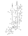
図1は、図2に詳細に示す水力発電設備1000に対する水門の構成例の詳細を示す。水門100(ここでは、ローラゲート)を表すため、堰は水門収容部120内に中継ローラ装置130に接する水門板110を備えている。水門収容部120は、それぞれスライドレールを構成するための溝を有する第1収容レール121と第2収容レール122を備えている。水門板110の両端は、第1および第2収容レール121、122の溝内にスライド(摺動)自在に取り付けられている。水門板110は、図2の中継ローラ装置のコード131によって保持される。コード131(本実施例では、ケーブル形状)は、水門110からガイドローラ、特に転向ローラ132を超え、さらにケーブルドラム133を超えて、中継ローラ装置130のフレームに案内される。ケーブルドラムは、水門駆動装置200に設けられた非同期機210の歯車機構220によって駆動される。ここで、非同期機210には、エアブレーキ230が割り当てられている。さらに、図1は歯車機構220の非同期機210と、ローラゲートの形状の水門100のコード131を有するケーブルドラム133の構成を示す。
FIG. 1 shows details of a sluice configuration example for the hydroelectric
水門板110は、トン領域の実質的な重さを有し、例えば本実施例の場合32トンの重さを有する。また、水門収容部120内における落下高さは数メートル、例えば10メートルまたは15メートルにも及ぶ。水門板110が図1に示す下部に緩衝なしに衝突した場合、すなわち、自由落下により閉鎖した場合、少なくとも水門板110および水門の収容部が破壊され、最悪のシナリオでは水門100が使用不能となるおそれがある。したがって、パッシブであると同時に、水門板110の降下位置への制御された移動および制動のための手段を設ける必要がある。
The
水門の緊急閉鎖は、水力発電タービンの速度超過のおそれが生じた場合(すなわち、例えばタービンブレードまたはタービンバケット等がピッチアウトされた場合)に、起こりえる。より可能性が低い別の場合として、例えば堆積物がデブリキャッチャーまたはインレットグリルを乗り越えた場合に、例えば堆積物から異物が流入するおそれがある場合がある。図1に示す態様または図2に示す態様の水門110は、概略的に示したタービン400のタービンパイプの正面に配置されていてもよい。水門の水門板110は、水力発電設備1000の水流500の前側においてゲート弁として機能する。しかし、水門100は、例えば、ごみ取り格子の一部、または、(図示しない)デブリキャッチャーの一部として、タービンパイプの上流位置に形成されていてもよい。
An emergency sluice closure can occur when there is a risk of overspeeding the hydropower turbine (ie, when, for example, a turbine blade or turbine bucket is pitched out). As another less likely case, there may be a risk that foreign matter may flow from the deposit, for example, when the deposit gets over a debris catcher or inlet grill. The
図2をさらに参照すると、水門収容部120のガイドの前面部123および背面部124と、コード131に吊り下げられた水門板110を、個別に概略的に示している。一方、水門板110は降下位置(ここでは、緊急閉鎖位置)に表示されている。すなわち、水門板110は、下限301に支えられるともに、タービン400の前方のタービンパイプ300の上限302に接している。下限301の直上の下部降下範囲B10の範囲に対して、水門板110を水門駆動装置200によって制動するための、展開形態に従って説明される特別な制御範囲が提供される。上部の走行範囲B90の範囲については、ここで詳述する水門駆動装置200の制御および/または閉制御の好ましい第1の部分によって制御される。
With further reference to FIG. 2, the
図2をさらに参照すると、水門駆動装置200は、モータまたは発電機として動作させることが可能な可変回転速度nを有する非同期機210と歯車機構220に加えて、非同期機210に割り当てられたエアブレーキ230を有する。エアブレーキ230は、非同期機210のロータとの共通シャフト201上に配置されている。具体的には、本実施例のエアブレーキ230は、非同期機210のロータが非同期機210のステータに摩擦接触によって接続可能となることで形成されている。アクチュエータ部240は、制動ばね250の力に対抗するように作用する。これは、適当な接続手段260によって達成される。制動ばね250によると、アクチュエータ部240を作動させることなく、ロータが非同期機210のステータと摩擦係合する効果がもたらされる。アクチュエータ部240を作動させることなく、エアブレーキ230が有効となり、非同期機210はしっかりと固定される。
With further reference to FIG. 2, the
図2に図示されていない第1の支持状態において、水門板110は上部位置に保持され、タービンパイプ300を解放して水流500がタービンパイプ300を流れるようにし、これによりタービン400を駆動する。エアブレーキは、水門板110に作用する重力を受け止める必要はない。この重力は、ここでは詳細に示していない他の構成によって、阻止および/または支えるようにしてもよい。
In a first support state, not shown in FIG. 2, the
保持位置HP1は、図2において第1の矢印によって示される。図2に示すように水門板110は第2の固定状態に移されることができ、アクチュエータ部240がエアブレーキ230を解放した後、図2において第2の矢印によって示されるように、下部の停止位置HP2に移行される。このため、アクチュエータ部240による制動ばね250への力により、制動ばね250のロータに対する圧力が低下し、ロータとステータの摩擦係合が生じる。この場合、非同期機210のロータは、回転磁界を自動生成するために、ステータ内において回転速度nに従って回生運転の方向に回転させることができる。
The holding position HP1 is indicated by the first arrow in FIG. As shown in FIG. 2, the
水門駆動装置200の動作は、図3に詳細に示されている。ここで、類似もしくは同一の特徴、または、類似もしくは同一の機能を有する特徴は、特に同一の参照符号を用いて参照され、これにより、これらの参照符号に対応する上記の説明を参照することが可能となる。
The operation of the
図3の本実施例の場合、アクチュエータ部240は蓄圧器241を有する。蓄圧器241は、アクチュエータ圧力管242およびその内部に設けられた制御弁243を介して、ガスばねアキュムレータ244に対して開放することができる。信号通知部270は、緊急閉鎖状況に関する信号を、信号線271を経由して制御端子243.1に伝達するために設けられている。制御端子243.1は、例えば、制御弁243のバルブピストン243.2を動かすための磁気コイルであってもよい。ガスばねアキュムレータ244が圧力媒体によって加圧されると、ガスばねアキュムレータ244は制動ばね250の圧縮力DKの抗力GKによって制動ばね250を解放することができる。これにより、非同期機210のステータ内のロータは可動位置に案内され、ステータ内で回転可能となる。これは、エアブレーキ230の開放に対応する。
In the case of this embodiment shown in FIG. 3, the
水門(ローラゲート)駆動装置200の機械的な動作原理は次のとおりである。ウィンチシステム、ここでは、ガイドローラの中継ローラ装置130は、ケーブルドラム133上のコード131によって供給される。ケーブルドラムは水門駆動装置200、特にモータとして機能する非同期機210によって完全に駆動され、非同期機210は歯車機構220を駆動するとともに、歯車機構220によって転向ローラ132を駆動する。したがって、ローラゲートの水門板110は水流500または水力発電設備1000のタービンパイプ300を閉鎖するように機能する。
The mechanical operation principle of the sluice gate (roller gate) driving
通常運転中、電力網600は、3相電流I(ここでは、3相に対する線I1、I2、I3で示す)を生成するために利用することができる。電流は、無停電電源装置を用いることなく、運転用回路の第1部分における周波数変換器712を用いるだけで、非同期機210の第1電線束を介して供給することができる。リレーまたは同様の電気機械式のスイッチ720(ここでは、通常運転用のスイッチの形態)が非通電状態にある場合、非同期機210を駆動させることができるように、電力供給線Iの3相電流I1、I2、I3は非同期機210に電気的に接続されている。このため、通常運転用のスイッチ720は、周波数変換器712を介して電線711に接続するための分岐線713に配置されている。これは、スイッチの非導通状態、すなわち、非活性化情報において生じる。周波数変換器712は、制動抵抗器を有する3相周波数変換器である。この場合において、無停電電源システムを設けることができる。無停電電源システムは、例えば、対応する数のバッテリーとバイパス回路を有し、3相の400Vの動作電圧であってもよい。本発明の場合のように、エアブレーキ230は、制動ばね250の制動ばね力によって提供される制動圧によって作動させるようにしてもよい。
During normal operation, the
通常運転用のスイッチ720が制御電流によって活性化されていない状態にある場合、スイッチ720は開いた状態となり、分岐線713を分離する。対応する制御信号線720’は、通常運転用のスイッチ720に導通している。この状態は、電力供給を受けていない非同期機210の状態に相当する。ここで、電力供給は、電力網600からの電力供給であってもよいし、本実施例では設置されていない無停電電源装置(UPS)からの電力供給であってもよい。なお、個々のケースでは、無停電電源装置が利用可能としてもよい。非同期機210は例えば400Vで動作し、3〜50ヘルツの周波数と対応する交流電圧を有していてもよい。運転用回路700のうちの緊急運転用に設けられた第2の部分において、運転用回路700は、特に電力生成を伴う(回生モードの)単独運転のための第2電線束730として構成される。単独運転において、非同期機210は、単独運転における発電機として動作するように構成される。
When the
上述のエアブレーキ230の解除において、水門100の水門板110にかかる重力は非同期機210のステータ内でのロータの回転運動を生成し、これにより、水門駆動装置200の制御および/または閉制御に対するエネルギーの自己供給を確保する。緊急運転ライン714における励磁コンデンサから成るコンデンサアレイ731と、3相電流I1、I2、I3に対する複数の負荷抵抗から成る第1段の負荷抵抗群732と、3相電流I1、I2、I3に対する複数の負荷抵抗から成る第2の負荷抵抗群733は、緊急運転部分730に対する適切な負荷スイッチ(負荷接触器)によって接続することができる。第1の負荷スイッチ721は、例えば無効電力および励磁コンデンサの回転磁界によって生成される制御電流に接続することができる。第2の緊急運転用のスイッチ722も、同様に、回転磁界およびこれによって生成された電流を制御電流として接続することができる。対応する制御信号線721’、722’は、緊急運転用のスイッチ721、722に接続されている。
In releasing the
基本的に、非同期機210は単独運転における限られた条件下で、すなわち、電力網600に接続することなく、発電機として、例えば非常用電源として動作させることができる。単独運転のための好ましい選択肢は、自励誘導発電機として運転することである。磁化のために誘導性無効電力および/または容量性無効電力を提供することができる外部の3相電力網600に接続することなく、無効電力は、それ自身が容量性無効電力を提供する並列接続されたコンデンサアレイ731によって提供することができる。特に、モータは誘導性無効電力を生成する。
Basically, the
単独運転の場合、周波数、特に一定の周波数は周波数変換器712によって決定される。電圧振幅は、相電流の最大振幅を考慮して制御することができる。過負荷の場合、必要に応じて電圧振幅を低下させることができる。適切な閉制御または制御用の電子機器を用いることで、ここで提案する非同期発電機によって高品質な単独運転を実現することができる。このため、複数の励磁コンデンサ731.1、731.2、731.3と、第1の複数の接続可能な負荷抵抗732.1、732.2、732.3と、第2の複数の接続可能な負荷抵抗733.1、733.2、733.3が設けられる。ここで、3つの素子は、それぞれ第2電線束730の第1、第2および第3の位相に対して設けられる。
In the case of islanding, the frequency, particularly a constant frequency, is determined by the
基本的に、電力網600に接続された第1電線束710に係る運転用回路の第1の部分において、無停電電源装置は不要となる。ここで提示した実施例の利点は、無停電電源装置を省略できることにある。基本的に、無停電電源装置(UPS)は、電力網600の障害時において、重要な電気負荷の供給を確保するために使用される。しかし、無停電電源装置(UPS)の単純な設計では、電力供給は、接続された負荷の機能を損なうことなく許容される期間、例えば数ミリ秒といった短い期間に亘って中断されてもよい。
Basically, the uninterruptible power supply is not required in the first portion of the operation circuit related to the first wire bundle 710 connected to the
図4は、運転用回路700、具体的には、運転用回路700の第2の部分を用いた(すなわち、第2電線束730を用いるとともに緊急運転回路に基づいて)水門駆動装置200の緊急閉鎖を制御する方法におけるステップのシーケンスを詳細に示す。
FIG. 4 illustrates an emergency operation of the
方法の開始時における最初のステップVS1において、運転用回路700は通常運転中である。すなわち、通常運転用のスイッチ720に電流が印加され、これによりスイッチ720は図3に示すように閉じている。非同期機210は、周波数変換器712と通常運転用のスイッチ720を介して、電力網600からの電力供給を用いてモータとして動作させることができる。第2の方法ステップVS2において緊急閉鎖状況が通知されると、水門駆動装置200は基本的に電力網600からの電力供給を用いて周波数変換器712によって動作させることができる。通常運転中、水門駆動装置は周波数変換器712によって異なる速度、および、必要に応じて可変速度で動作させることができる。これは、例えば、加速ランプおよび減速停止ランプを用いて水門板110をゆっくりと持ち上げる目的、または、加速ランプおよび減速停止ランプを用いて水門板110をゆっくりと下ろす目的で行ってもよい。基本的に、電力網600が利用可能な場合、緊急閉鎖は、特定の減速停止ランプを用いて行うこともできる。特に、かかる方法は、非同期機210の回生運転を用いた通常の電気制動(電気ブレーキ)方法を含んでいてもよい。
In the first step VS1 at the start of the method, the
次の方法ステップVS3において、電力網600からの電力供給が得られないことが通知された場合(Yのパス)、本発明の水門駆動装置200の制御方法によると、水門駆動装置の制御方法をパッシブに達成できるという効果がもたらされる。これは、次のことを意味する。すなわち、この場合には、電力網600からの外部のエネルギー供給なしで、しかも、必要に応じて周波数変換器712に隣接して設置可能な無停電電源装置からのエネルギー供給もなしで、水門駆動装置200の制御方法を実行できることを意味する。
When it is notified in the next method step VS3 that the power supply from the
図3に示した実施例の変形例では、無停電電源装置(UPS)を設けることができる。しかし、ここに示すパッシブな方法によると、高価な無停電電源システムの使用を避けることができる。 In a modification of the embodiment shown in FIG. 3, an uninterruptible power supply (UPS) can be provided. However, the passive method shown here can avoid the use of an expensive uninterruptible power supply system.
方法ステップVS2、VS3において、電力供給なしで水門100を緊急閉鎖しなければならない状況が起きた場合、このことは信号通知部270によって検出され、通知が行われる。第4の方法ステップVS4において、エアブレーキ230は、例示した上記のアクチュエータ部240によって解放することができる。
In the method steps VS2, VS3, if a situation arises where the
この場合、水門板110にかかる重力Gに応じた、非同期機210の発電機としての動作が行われ、これにより方法ステッVS5において、励磁コンデンサ731.1、731.2、731.3のステージ731によって回転磁界が生成される。対応する電圧と、これにより制御電流線720’に生成された制御電流は、通常運転用リレー720が非通電時に活性化されるリレーである場合、リレー720が自動で開かないときに、リレー720を開くために使用することができる。
In this case, the operation of the
制御電流線721’に供給される制御電流は、電圧および/または水門の位置に応じて、または、第1回転速度n−としつつ、負荷抵抗732.1、732.2、732.3から成る第1段732を接続することができる。これは、例えば、図2に示した走行範囲B90の50%ないし95%の区間を下降するときの水門板110を、適切に制動するために行うことができる。
The control current supplied to the control
回転速度n+がさらに増加した場合、または、第2制御電流が第2制御電圧線722’に達した場合、負荷抵抗733.1、733.2、733.3から成る第2段733を接続するために、第2の緊急運転用のスイッチ722を切り替えることができる。追加的または代替的に、ローラゲートの位置を、切り替えを決定するための要素としてもよい。第2のより急勾配の減速停止ランプにおいて、これは、図2に示した降下範囲B10における水門板110の実質的な残留制動(残留ブレーキ)をもたらす。したがって、方法ステップVS6において第1の減速停止ランプは第1段の負荷抵抗群732によって実現することができ、一方、方法ステップVS7において第2の減速停止ランプは第2段の負荷抵抗群733によって実現することができる。かくして、緊急運転中、第1および第2の減速停止ランプは、運転用回路の第2の部分、特に第2電線束730を用いてパッシブに実行することができる。このようにして、電力網(からの供給)がなく、かつ/または周波数変換器712がない場合であっても、水門板110の安全な制動が実現される。また、上記のアクチュエータ部240によって非導通時に開状態となる制御弁243を用いて、水門板110のパッシブな動作を実現することができる。
When the rotation speed n + further increases or when the second control current reaches the second
電力網600からの電力供給が存在し、周波数変換器712が機能する場合(Nのパス)においても、方法ステップVS4およびVS5を実行してもよい。これにもかかわらず、方法ステップVS9において、水門板110の降下を電流制御してもよい。本実施例の方法は、ステップVS8において水門板が下降した状態で終了する。
Method steps VS4 and VS5 may also be performed when power supply from
100 水門(Wasserschutz)
110 水門板(Schuztafel)
120 水門収容部(Schutzlagerung)
121、122 収容レール(Lagerschiene)
123 ガイド前面部(vorderer Teil einer Fuhrung)
124 ガイド背面部(hinterer Teil einer Fuhrung)
130 中継ローラ装置(Ubertragungs-Rollwerk)
131 コード(Zugstrang)
132 転向ローラ(Umlenkrolle)
133 ケーブルドラム(Seiltrommel)
200 水門駆動装置(Wasserschutz-Antrieb)
201 共通シャフト(gemeinsame Welle)
210 非同期機(Asynchronmaschine)
220 歯車機構(Getriebe)
230 エアブレーキ(Luftbremse)
240 アクチュエータ部(Aktuatoreinheit)
241 蓄圧器(Druckspeicher)
242 アクチュエータ圧力管(Aktuatordruckleitung)
243 制御弁(Regelventil)
243.1 制御端子(Steueranschluss)
243.2 バルブピストン(Ventilkkolben)
244 ガスばねアキュムレータ(Gasfederspeicher)
250 制動ばね(Bremsfeder)
260 接続手段(Verbindungsmittel)
270 信号通知部(Signalisierungseinheit)
271 信号線(Signalleitung)
300 タービンパイプ(Turbinenrohr)
301 下限(untere Begrenzung)
302 上限(obere Begrenzung)
400 タービン(Turbine)
500 水流(Wasserlauf)
600 電力網(Stromnetz)
700 運転用回路(Betriebsschaltung)
710 第1電線束(erster Stromstrang)
711 電線(Netzleitung)
712 周波数変換器(Frequenzumrichter)
713 分岐線(Zweigleitung)
714 緊急運転ライン(Notbetriebsleitung)
720〜722 スイッチ(Schutz)
720’〜722’ 制御電流(制御信号)線(Steuerstromleitung, Steuersignalleitung)
730 第2電線束(zweiter Stromstrang)
731 コンデンサアレイ(Kondensatoranordnung)
731.1〜731.3 励磁コンデンサ(Erregungskondensator)
732 第1段の負荷抵抗群(erste Anordnung von Lastwiderstanden)
733 第2段の負荷抵抗群(tweite Anordnung von Lastwiderstanden)
732.1〜732.3、733.1〜733.3 負荷抵抗(Lastwiderstand)
1000 水力発電設備(Wasserkraftanlage)
DK 圧縮力
GK 反力
n 可変回転速度(variable Drehzahl)
100 Sluice (Wasserschutz)
110 Sluice board (Schuztafel)
120 Schutzlagerung
121, 122 Containment rail (Lagerschiene)
123 Guide front (vorderer Teil einer Fuhrung)
124 Guide back (hinterer Teil einer Fuhrung)
130 Relay roller device (Ubertragungs-Rollwerk)
131 code (Zugstrang)
132 Turning roller (Umlenkrolle)
133 Cable drum (Seiltrommel)
200 Sluice Drive (Wasserschutz-Antrieb)
201 Common shaft (gemeinsame Welle)
210 Asynchronmaschine
220 Gear mechanism (Getriebe)
230 Air brake (Luftbremse)
240 Actuator (Aktuatoreinheit)
241 Accumulator (Druckspeicher)
242 Actuator pressure tube (Aktuatordruckleitung)
243 Control valve (Regelventil)
243.1 Control terminals (Steueranschluss)
243.2 Valve piston (Ventilkkolben)
244 Gas Spring Accumulator (Gasfederspeicher)
250 Brake spring (Bremsfeder)
260 Connection means (Verbindungsmittel)
270 Signal Notification Unit (Signalisierungseinheit)
271 Signal line
300 Turbine pipe (Turbinenrohr)
301 Lower limit (untere Begrenzung)
302 Upper limit (obere Begrenzung)
400 Turbine
500 Current (Wasserlauf)
600 Power grid (Stromnetz)
700 Operation circuit (Betriebsschaltung)
710 1st wire bundle (erster Stromstrang)
711 Electric wire (Netzleitung)
712 Frequency converter (Frequenzumrichter)
713 Branch line (Zweigleitung)
714 Emergency Driving Line (Notbetriebsleitung)
720-722 switch (Schutz)
720'-722 'control current (control signal) line (Steuerstromleitung, Steuersignalleitung)
730 Second wire bundle (zweiter Stromstrang)
731 Capacitor array (Kondensatoranordnung)
731.1 to 731.3 Exciting capacitor (Erregungskondensator)
732 First stage load resistance group (erste Anordnung von Lastwiderstanden)
733 Second stage load resistance group (tweite Anordnung von Lastwiderstanden)
732.1 to 732.3, 733.1 to 733.3 Load resistance (Lastwiderstand)
1000 Hydroelectric power generation facility (Wasserkraftanlage)
DK Compression force GK Reaction force n Variable speed (variable Drehzahl)
本発明の第1の視点に係る方法は、水力発電設備における水門またはローラゲートに対する水門駆動装置を制御する方法であって、前記水門駆動装置は電動機もしくは非同期機、または、非同期モータ/発電機を備え、前記電動機または非同期機はエアブレーキを有し、前記方法は、電力供給が不十分であることが通知された場合、エアブレーキを解放するステップと、前記電動機または非同期機の自動運転と、を含み、前記電動機または非同期機は回転磁界が自励式で生成される、発電を伴う単独運転で運転される。
本発明の第2の視点に係る運転用回路は、水力発電設備における水門またはローラゲートに対する水門駆動装置を制御する運転用回路であって、前記水門駆動装置は電動機もしくは非同期機、または、非同期モータ/発電機を備え、前記電動機または非同期機はエアブレーキを有し、前記運転用回路は通常運転用の第1制御線と緊急運転用の第2制御線を有し、前記第2制御線は、発電を伴う単独運転で電動機または非同期機を自動運転するように構成され、回転磁界が自励式で生成され、少なくとも第1制御段階および/または閉制御段階のための第1段の負荷抵抗群と、第2制御段階および/または閉制御段階のための第2段の負荷抵抗群を有する。
本発明の第3の視点に係る水門駆動装置は、水力発電設備において、電動機または非同期機を制御するための、水門に対する水門駆動装置、または、ローラゲートに対するローラゲート駆動装置であって、前記電動機または非同期機はエアブレーキを有し、電力供給が不十分であることが通知された場合、エアブレーキを解放するように構成されたアクチュエータ部と、電動機または非同期機の自動運転のため、水門に対する水門駆動装置を制御する運転用回路と、を備え、前記運転用回路は前記電動機または非同期機を、発電を伴う単独運転で運転するように構成され、回転磁界は自励式で生成可能であり、少なくとも第1段の負荷抵抗群と第2段の負荷抵抗群を有する。
本発明の第4の視点に係る水力発電設備は水門またはローラゲートに対する電動機または非同期機を制御するために、上記の水門駆動装置を備え、前記非同期機はエアブレーキを有する。
方法に関する課題は、請求項1に係る方法によって達成される。本発明によると非同期モータはエアブレーキを備えており、かかる方法によると、緊急停止状況を検出すると本発明に係る次のステップ、すなわち、電力供給が不十分であるこが通知された(ないし、示された)場合、エアブレーキを解放するステップと、電動機の自動運転とを含む。ここで、電動機は回転磁界が自励式で生成され、発電を伴う(すなわち回生モードの)単独運転で運転される。
A method according to a first aspect of the present invention is a method for controlling a sluice gate drive device for a sluice or a roller gate in a hydroelectric power generation facility, wherein the sluice gate drive device includes an electric motor or an asynchronous machine, or an asynchronous motor / generator. The motor or asynchronous machine has an air brake, and the method releases the air brake when notified that power supply is insufficient; and automatic operation of the motor or asynchronous machine; The electric motor or asynchronous machine is operated in a single operation with power generation in which a rotating magnetic field is generated in a self-excited manner.
An operation circuit according to a second aspect of the present invention is an operation circuit for controlling a sluice drive device for a sluice or a roller gate in a hydroelectric power generation facility, and the sluice drive device is an electric motor, an asynchronous machine, or an asynchronous motor A generator, the electric motor or the asynchronous machine has an air brake, the driving circuit has a first control line for normal operation and a second control line for emergency operation, and the second control line is A first stage load resistance group for at least the first control stage and / or the closed control stage, wherein the electric motor or the asynchronous machine is automatically operated in a single operation with power generation, and the rotating magnetic field is generated by self-excitation. And a second stage load resistance group for the second control stage and / or the closed control stage.
A sluice gate drive device according to a third aspect of the present invention is a sluice gate drive device for a sluice gate or a roller gate drive device for a roller gate for controlling an electric motor or an asynchronous machine in a hydroelectric power generation facility. Or the asynchronous machine has an air brake and when notified that the power supply is inadequate, the actuator part configured to release the air brake and the sluice gate for automatic operation of the motor or asynchronous machine An operation circuit for controlling the sluice drive device, the operation circuit is configured to operate the electric motor or the asynchronous machine in a single operation with power generation, and the rotating magnetic field can be generated by self-excitation, It has at least a first stage load resistance group and a second stage load resistance group.
A hydroelectric power generation facility according to a fourth aspect of the present invention includes the sluice drive device described above in order to control an electric motor or an asynchronous machine for a sluice or a roller gate, and the asynchronous machine has an air brake.
The object of the method is achieved by a method according to
水門駆動装置の場合には、アクチュエータ部はガスばねアキュムレータを有することが特に有利であることが判明している。ここで、エアブレーキは、ガスばねアキュムレータによって解放されるようにしてもよい。さらに、アクチュエータ部は、電源(すなわち、主電源を伴う、または、無停電電源回路からの電力供給を伴う通常運転中)に接続された制御弁を、ガスばねアキュムレータと蓄圧器の間のアクチュエータ圧力管内に有することが好ましい。制御弁は非通電時に開状態となるため、アクチュエータ部は、ガスばねアキュムレータと蓄圧器の間のアクチュエータ圧力管において、非通電時に開状態となる制御弁を開くことによって、エアブレーキへのガス圧の供給を確保する。エアブレーキは、ガス圧の下で、エアブレーキの制動ばねのばね力に抗して自動的に開き、これにより、電動機のロータをステータ内で回転するように放出することができる。したがって、回転磁界が生成される。 In the case of a sluice drive, it has proved particularly advantageous for the actuator part to have a gas spring accumulator. Here, the air brake may be released by a gas spring accumulator. In addition, the actuator section connects the control valve connected to the power source (ie during normal operation with the main power supply or with power supply from the uninterruptible power supply circuit), the actuator pressure between the gas spring accumulator and the accumulator. It is preferable to have in the tube. Since the control valve is open when not energized, the actuator section opens the control valve that is open when deenergized in the actuator pressure tube between the gas spring accumulator and the accumulator , thereby providing the gas pressure to the air brake. Ensure the supply of The air brake automatically opens under the gas pressure against the spring force of the brake spring of the air brake, thereby allowing the motor rotor to be released for rotation in the stator. Therefore, a rotating magnetic field is generated.
電力網600からの電力供給が存在し、周波数変換器712が機能する場合(Nのパス)においても、方法ステップVS4およびVS5を実行してもよい。これにもかかわらず、方法ステップVS9において、水門板110の降下を電流制御してもよい。本実施例の方法は、ステップVS8において水門板が下降した状態で終了する。
なお、特許請求の範囲に付記した図面参照符号は、図示した形態に限定することを意図するものではなく、専ら理解を助けるためのものである。
また、本発明において、さらに以下の形態が可能である。
[形態1]
好ましくは水力発電設備(1000)における水門(100)、特にローラゲートに対する水門駆動装置(200)を制御する方法であって、
前記水門駆動装置は電動機、特に非同期機(210)、特に非同期モータ/発電機を備え、
前記電動機、特に非同期機(210)はエアブレーキ(230)を有し、
前記方法は、電力供給が不十分であることが通知された場合、エアブレーキ(230)を解放するステップと、
前記電動機、特に非同期機(210)の自動運転と、を含み、
前記電動機、特に非同期機は回転磁界が自励式で生成される、発電を伴う単独運転で運転される、
ことを特徴とする方法。
[形態2]
電力供給が十分であることが通知された場合、
電力供給、特に電力網(600)および/または無停電電源装置(UPS)のための設備からの電力供給を検出するステップをさらに含み、
前記電動機、特に非同期機(210)は前記電力供給を用いて運転される、
形態1に記載の方法。
[形態3]
前記非同期機(210)は、特に電力供給が十分であることが通知された場合、可変回転速度で運転される、
形態1または2に記載の方法。
[形態4]
特に電力供給が十分であることが通知された場合、特に非同期機(210)の電気的制御および/または周波数変換器(712)に基づいて、非同期機(210)は水門をゆっくりと閉鎖するように操作され、かつ/または、非同期機に対する電気的減速停止ランプ(勾配)が実行される、
形態1ないし3のいずれか一に記載の方法。
[形態5]
緊急閉鎖状況を検出するステップ、および/または、
電力供給が不十分であること、特に欠如することを検出するステップをさらに含む、
形態1ないし4のいずれか一に記載の方法。
[形態6]
前記電力供給が不十分であることは、電力網(600)からの電力供給が不十分であること、および/または、無停電電源装置(UPS)のための設備からの電力供給が不十分であることを含む、
形態5に記載の方法。
[形態7]
電力供給が不十分であることが通知された場合、非同期機(210)は異なる速度、特に予め定められたほぼ一定の第1および第2回転速度で動作させられ、特に電力供給を受けることなく動作させられる、
形態1ないし6のいずれか一に記載の方法。
[形態8]
エアブレーキ(230)の解放は、エアブレーキ(230)の自動的な解放、特に非同期機(210)のステータからロータが解放されることで行われる、
形態1ないし7のいずれか一に記載の方法。
[形態9]
非同期機(210)は水門(100)の水門板(110)にかかる重力(G)の影響の下で駆動され、回転磁界は特に励磁コンデンサ(731.1、731.2、731.3)から成るコンデンサアレイ(731)によって生成される、
形態1ないし8のいずれか一に記載の方法。
[形態10]
特にエアブレーキ(230)に対する負荷を切り替えつつ、非同期機(210)に対して、少なくとも1つの制御段階および/または閉制御段階が実行され、特に(好ましくは制動段階として)第1制御段階および/または閉制御段階(VS6)と、(好ましくは停止段階として)第2制御段階および/または閉制御段階(VS7)が実行される、
形態1ないし9のいずれか一に記載の方法。
[形態11]
少なくとも1つの第1段(732)の負荷抵抗群(732.1、732.2、732.3)が接続され、好ましくは第1段および第2段(733)の負荷抵抗群(733.1、733.2、733.3)が接続されている、
形態1ないし10のいずれか一に記載の方法。
[形態12]
非同期機(210)は少なくとも2つの回転速度段で制御され、特に第1回転速度段は電圧および/または水門の位置に応じて選択され、かつ/または、第2回転速度段は電圧および/または水門の位置に応じて選択される、
形態1ないし11のいずれか一に記載の方法。
[形態13]
好ましくは水力発電設備(1000)における水門(100)、特にローラゲートに対する水門駆動装置(200)を制御する運転用回路(700)であって、
前記水門駆動装置は電動機、特に非同期機(210)、特に非同期モータ/発電機を備え、
前記電動機、特に非同期機(210)はエアブレーキ(230)を有し、
前記運転用回路(700)は特に通常運転用の第1制御線と特に緊急運転用の第2制御線を有し、
前記第2制御線は、発電を伴う単独運転で電動機、特に非同期機を自動運転するように構成され、回転磁界が自励式で生成され、特に少なくとも第1制御段階および/または閉制御段階(VS5)のための第1段(732)の負荷抵抗群と、第2制御段階および/または閉制御段階(VS7)のための第2段(733)の負荷抵抗群を有する、
ことを特徴とする運転用回路。
[形態14]
好ましくは水力発電設備(1000)において、電動機、特に非同期機(210)を制御するための、水門(100)に対する水門駆動装置(200)、特にローラゲートに対するローラゲート駆動装置であって、
前記電動機、特に非同期機(210)はエアブレーキ(230)を有し、
特に電力供給が不十分であることが通知された場合、エアブレーキ(230)を解放するように構成されたアクチュエータ部(240)と、
電動機、特に非同期機(210)の自動運転のため、水門(100)に対する水門駆動装置(200)を制御する運転用回路(700)と、を備え、
前記運転用回路(700)は前記電動機、特に非同期機(210)を、発電を伴う単独運転で運転するように構成され、
回転磁界は自励式で生成可能であり、特に少なくとも第1段(732)の負荷抵抗群と第2段(733)の負荷抵抗群を有する、
ことを特徴とする水門駆動装置(200)。
[形態15]
緊急閉鎖状況を検出し、かつ/または、通知するように構成された信号通知部(270)をさらに備える、
形態14に記載の水門駆動装置(200)。
[形態16]
前記アクチュエータ部(240)はガスばねアキュムレータを有し、エアブレーキ(230)の制動ばね(250)は前記ガスばねアキュムレータにより解放可能である、
形態14または15に記載の水門駆動装置(200)。
[形態17]
前記アクチュエータ部(240)は、特にエアブレーキ(230)の制動ばね(250)を操作するために、通電時に閉状態となり非通電時に開状態となる制御弁(243)を、蓄圧器(241)とガスばねアキュムレータ(244)の間のアクチュエータ圧力管(242)内に有する、
形態14ないし16のいずれか一に記載の水門駆動装置(200)。
[形態18]
前記運転用回路(700)は、特に第2電線束(730)において、複数の励磁コンデンサ(731.1、731.2、731.3)を有し、少なくとも第1の複数の接続可能な負荷抵抗(732.1、732、2.732.3)を有する、
形態14ないし17のいずれか一に記載の水門駆動装置(200)。
[形態19]
前記運転用回路(700)は、特に第2電線束(730)において、第1の複数の接続可能な負荷抵抗(732.1、732、2.732.3)を有し、第2の複数の接続可能な負荷抵抗(733.1、733.2、733.3)を有する、
形態14ないし18のいずれか一に記載の水門駆動装置(200)。
[形態20]
前記運転用回路(700)は、特に第2電線束(730)において、接続可能な第1段(732)および/または第2段(733)の負荷抵抗群を、電圧および/または水門の位置に応じて、特に第1および/または第2リレーないし同様の電気機械式スイッチ(721、722)を介して接続するように構成されている、
形態14ないし19のいずれか一に記載の水門駆動装置(200)。
[形態21]
前記運転用回路(700)は、特に第1電線束(710)において、特に電力網(600)からの通常の制御電流源によって、非同期機(210)を可変回転速度で電気的に制御するように構成されている、
形態14ないし20のいずれか一に記載の水門駆動装置(200)。
[形態22]
前記運転用回路(700)は、特に第1電線束(710)において、無停電電源装置(UPS)のための設備に依存しない、
形態14ないし20のいずれか一に記載の水門駆動装置(200)。
[形態23]
水力発電設備(1000)、水門(100)、特にローラゲートに対する電動機、特に非同期機(210)を制御するために、形態14ないし22のいずれか一に記載の水門駆動装置(200)を備え、
前記非同期機(210)はエアブレーキ(230)を有する、
ことを特徴とする、水力発電設備(1000)。
Method steps VS4 and VS5 may also be performed when power supply from
It should be noted that the reference numerals attached to the claims are not intended to be limited to the illustrated form, but are solely for the purpose of assisting understanding.
Further, in the present invention, the following modes are possible.
[Form 1]
Preferably a method for controlling a sluice gate (100) in a hydroelectric power generation facility (1000), in particular a sluice gate drive (200) for a roller gate,
Said sluice drive comprises an electric motor, in particular an asynchronous machine (210), in particular an asynchronous motor / generator,
The electric motor, in particular the asynchronous machine (210) has an air brake (230),
Said method releasing the air brake (230) when notified of insufficient power supply;
Automatic operation of the electric motor, in particular the asynchronous machine (210),
The electric motor, particularly the asynchronous machine, is operated by a single operation with power generation, in which a rotating magnetic field is generated by self-excitation,
A method characterized by that.
[Form 2]
If you are notified that the power supply is sufficient,
Further comprising detecting a power supply, in particular a power supply from a facility for the power grid (600) and / or uninterruptible power supply (UPS),
The electric motor, in particular the asynchronous machine (210) is operated using the power supply,
The method according to
[Form 3]
The asynchronous machine (210) is operated at a variable rotational speed, particularly when notified that power supply is sufficient,
The method according to
[Form 4]
Especially when notified that the power supply is sufficient, the asynchronous machine (210) slowly closes the sluice, especially based on the electrical control of the asynchronous machine (210) and / or the frequency converter (712). And / or an electrical deceleration stop ramp (gradient) for the asynchronous machine is executed,
The method according to any one of
[Form 5]
Detecting an emergency closure situation, and / or
Further comprising detecting an inadequate power supply, in particular a lack of power supply,
The method according to any one of
[Form 6]
The insufficient power supply means that the power supply from the power network (600) is insufficient and / or the power supply from the facility for the uninterruptible power supply (UPS) is insufficient. Including that,
The method according to aspect 5.
[Form 7]
If notified that the power supply is inadequate, the asynchronous machine (210) is operated at different speeds, in particular at predetermined substantially constant first and second rotational speeds, without any particular power supply. Operated,
The method according to any one of
[Form 8]
The release of the air brake (230) is performed by automatically releasing the air brake (230), particularly by releasing the rotor from the stator of the asynchronous machine (210).
The method according to any one of
[Form 9]
The asynchronous machine (210) is driven under the influence of gravity (G) applied to the sluice board (110) of the sluice (100), and the rotating magnetic field is generated from the excitation capacitors (731.1, 731.2, 731.3) in particular. Generated by a capacitor array (731) comprising:
The method according to any one of
[Mode 10]
At least one control phase and / or a closed control phase is carried out on the asynchronous machine (210), in particular switching the load on the air brake (230), in particular the first control phase and / or (preferably as a braking phase) Or a closed control phase (VS6) and a second control phase and / or a closed control phase (VS7) (preferably as a stop phase) are performed,
The method according to any one of
[Form 11]
At least one first stage (732) load resistance group (732.1, 732.2, 732.3) is connected, preferably the first stage and second stage (733) load resistance group (733.1). , 733.2, 733.3) are connected,
The method according to any one of
[Form 12]
The asynchronous machine (210) is controlled with at least two rotational speed stages, in particular the first rotational speed stage is selected depending on the voltage and / or the position of the sluice and / or the second rotational speed stage is voltage and / or Selected according to the position of the sluice,
The method according to any one of
[Form 13]
Preferably, an operation circuit (700) for controlling the sluice gate (100) in the hydroelectric power generation facility (1000), particularly the sluice gate drive device (200) for the roller gate,
Said sluice drive comprises an electric motor, in particular an asynchronous machine (210), in particular an asynchronous motor / generator,
The electric motor, in particular the asynchronous machine (210) has an air brake (230),
The operating circuit (700) has in particular a first control line for normal operation and a second control line for emergency operation in particular,
The second control line is configured to automatically operate an electric motor, particularly an asynchronous machine, in a single operation with power generation, and a rotating magnetic field is generated in a self-excited manner. In particular, at least the first control stage and / or the closed control stage (VS5). ) For the first stage (732) and the second stage (733) for the second control stage and / or the closed control stage (VS7),
A driving circuit characterized by that.
[Form 14]
A sluice gate drive device (200) for a sluice gate (100), in particular a roller gate drive device for a roller gate, for controlling an electric motor, in particular an asynchronous machine (210), in a hydroelectric power generation facility (1000),
The electric motor, in particular the asynchronous machine (210) has an air brake (230),
An actuator portion (240) configured to release the air brake (230), particularly when notified of insufficient power supply;
An operation circuit (700) for controlling the sluice drive device (200) for the sluice (100) for automatic operation of the electric motor, particularly the asynchronous machine (210),
The operation circuit (700) is configured to operate the electric motor, particularly the asynchronous machine (210), in a single operation with power generation,
The rotating magnetic field can be generated in a self-excited manner, and particularly has at least a load resistance group of the first stage (732) and a load resistance group of the second stage (733).
A sluice drive device (200) characterized in that.
[Form 15]
Further comprising a signal notifier (270) configured to detect and / or notify an emergency closure situation;
The sluice drive device (200) according to embodiment 14.
[Form 16]
The actuator part (240) has a gas spring accumulator, and the brake spring (250) of the air brake (230) can be released by the gas spring accumulator.
The sluice drive device (200) according to embodiment 14 or 15.
[Form 17]
The actuator section (240) is provided with a control valve (243) that is closed when energized and opened when deenergized, particularly for operating the brake spring (250) of the air brake (230). And in the actuator pressure tube (242) between the gas spring accumulator (244),
The sluice drive device (200) according to any one of forms 14 to 16.
[Form 18]
The operation circuit (700) has a plurality of exciting capacitors (731.1, 731.2, 731.3), particularly in the second wire bundle (730), and at least a first plurality of connectable loads. Having resistors (732.1, 732, 2.732.3),
The sluice drive device (200) according to any one of forms 14 to 17.
[Form 19]
The operating circuit (700) has a first plurality of connectable load resistors (732.1, 732, 2.732.3), particularly in the second wire bundle (730), and a second plurality A load resistance (733.1, 733.2, 733.3) that can be connected,
The sluice drive device (200) according to any one of forms 14 to 18.
[Form 20]
The operation circuit (700) is configured to connect the load resistance group of the first stage (732) and / or the second stage (733) that can be connected, particularly in the second wire bundle (730), to the voltage and / or sluice gate position. In accordance with, in particular configured to connect via first and / or second relays or similar electromechanical switches (721, 722),
The sluice drive device (200) according to any one of forms 14 to 19.
[Form 21]
The operating circuit (700) is adapted to electrically control the asynchronous machine (210) at a variable rotational speed, particularly in the first wire bundle (710), in particular by a normal control current source from the power grid (600). It is configured,
The sluice drive device (200) according to any one of forms 14 to 20.
[Form 22]
The operating circuit (700) is not dependent on equipment for an uninterruptible power supply (UPS), particularly in the first wire bundle (710),
The sluice drive device (200) according to any one of forms 14 to 20.
[Form 23]
In order to control the hydraulic power generation facility (1000), the sluice gate (100), in particular the motor for the roller gate, in particular the asynchronous machine (210), the sluice gate drive device (200) according to any one of forms 14 to 22 is provided,
The asynchronous machine (210) has an air brake (230),
A hydroelectric power generation facility (1000) characterized by that.
Claims (23)
前記水門駆動装置は電動機、特に非同期機(210)、特に非同期モータ/発電機を備え、
前記電動機、特に非同期機(210)はエアブレーキ(230)を有し、
前記方法は、電力供給が不十分であることが通知された場合、エアブレーキ(230)を解放するステップと、
前記電動機、特に非同期機(210)の自動運転と、を含み、
前記電動機、特に非同期機は回転磁界が自励式で生成される、発電を伴う単独運転で運転される、
ことを特徴とする方法。 Preferably a method for controlling a sluice gate (100) in a hydroelectric power generation facility (1000), in particular a sluice gate drive (200) for a roller gate,
Said sluice drive comprises an electric motor, in particular an asynchronous machine (210), in particular an asynchronous motor / generator,
The electric motor, in particular the asynchronous machine (210) has an air brake (230),
Said method releasing the air brake (230) when notified of insufficient power supply;
Automatic operation of the electric motor, in particular the asynchronous machine (210),
The electric motor, particularly the asynchronous machine, is operated by a single operation with power generation, in which a rotating magnetic field is generated by self-excitation,
A method characterized by that.
電力供給、特に電力網(600)および/または無停電電源装置(UPS)のための設備からの電力供給を検出するステップをさらに含み、
前記電動機、特に非同期機(210)は前記電力供給を用いて運転される、
請求項1に記載の方法。 If you are notified that the power supply is sufficient,
Further comprising detecting a power supply, in particular a power supply from a facility for the power grid (600) and / or uninterruptible power supply (UPS),
The electric motor, in particular the asynchronous machine (210) is operated using the power supply,
The method of claim 1.
請求項1または2に記載の方法。 The asynchronous machine (210) is operated at a variable rotational speed, particularly when notified that power supply is sufficient,
The method according to claim 1 or 2.
請求項1ないし3のいずれか1項に記載の方法。 Especially when notified that the power supply is sufficient, the asynchronous machine (210) slowly closes the sluice, especially based on the electrical control of the asynchronous machine (210) and / or the frequency converter (712). And / or an electrical deceleration stop ramp (gradient) for the asynchronous machine is executed,
4. A method according to any one of claims 1 to 3.
電力供給が不十分であること、特に欠如することを検出するステップをさらに含む、
請求項1ないし4のいずれか1項に記載の方法。 Detecting an emergency closure situation, and / or
Further comprising detecting an inadequate power supply, in particular a lack of power supply,
5. A method according to any one of claims 1 to 4.
請求項5に記載の方法。 The insufficient power supply means that the power supply from the power network (600) is insufficient and / or the power supply from the facility for the uninterruptible power supply (UPS) is insufficient. Including that,
The method of claim 5.
請求項1ないし6のいずれか1項に記載の方法。 The asynchronous machine (210) is operated at different speeds, in particular at substantially constant first and second rotational speeds, in particular when it is informed that the power supply is inadequate, in particular receiving power supply. Can be operated without
7. A method according to any one of claims 1-6.
請求項1ないし7のいずれか1項に記載の方法。 The release of the air brake (230) is performed by automatically releasing the air brake (230), particularly by releasing the rotor from the stator of the asynchronous machine (210).
8. A method according to any one of claims 1 to 7.
請求項1ないし8のいずれか1項に記載の方法。 The asynchronous machine (210) is driven under the influence of gravity (G) applied to the sluice board (110) of the sluice (100), and the rotating magnetic field is generated from the excitation capacitors (731.1, 731.2, 731.3) in particular. Generated by a capacitor array (731) comprising:
9. A method according to any one of claims 1 to 8.
請求項1ないし9のいずれか1項に記載の方法。 At least one control phase and / or a closed control phase is carried out on the asynchronous machine (210), in particular switching the load on the air brake (230), in particular the first control phase and / or (preferably as a braking phase) Or a closed control phase (VS6) and a second control phase and / or a closed control phase (VS7) (preferably as a stop phase) are performed,
10. A method according to any one of claims 1-9.
請求項1ないし10のいずれか1項に記載の方法。 At least one first stage (732) load resistance group (732.1, 732.2, 732.3) is connected, preferably the first stage and second stage (733) load resistance group (733.1). , 733.2, 733.3) are connected,
11. A method according to any one of claims 1 to 10.
請求項1ないし11のいずれか1項に記載の方法。 The asynchronous machine (210) is controlled with at least two rotational speed stages, in particular the first rotational speed stage is selected depending on the voltage and / or the position of the sluice and / or the second rotational speed stage is voltage and / or Selected according to the position of the sluice,
12. A method according to any one of the preceding claims.
前記水門駆動装置は電動機、特に非同期機(210)、特に非同期モータ/発電機を備え、
前記電動機、特に非同期機(210)はエアブレーキ(230)を有し、
前記運転用回路(700)は特に通常運転用の第1制御線と特に緊急運転用の第2制御線を有し、
前記第2制御線は、発電を伴う単独運転で電動機、特に非同期機を自動運転するように構成され、回転磁界が自励式で生成され、特に少なくとも第1制御段階および/または閉制御段階(VS5)のための第1段(732)の負荷抵抗群と、第2制御段階および/または閉制御段階(VS7)のための第2段(733)の負荷抵抗群を有する、
ことを特徴とする運転用回路。 Preferably, an operation circuit (700) for controlling the sluice gate (100) in the hydroelectric power generation facility (1000), particularly the sluice gate drive device (200) for the roller gate,
Said sluice drive comprises an electric motor, in particular an asynchronous machine (210), in particular an asynchronous motor / generator,
The electric motor, in particular the asynchronous machine (210) has an air brake (230),
The operating circuit (700) has in particular a first control line for normal operation and a second control line for emergency operation in particular,
The second control line is configured to automatically operate an electric motor, particularly an asynchronous machine, in a single operation with power generation, and a rotating magnetic field is generated in a self-excited manner. In particular, at least the first control stage and / or the closed control stage (VS5). ) For the first stage (732) and the second stage (733) for the second control stage and / or the closed control stage (VS7),
A driving circuit characterized by that.
前記電動機、特に非同期機(210)はエアブレーキ(230)を有し、
特に電力供給が不十分であることが通知された場合、エアブレーキ(230)を解放するように構成されたアクチュエータ部(240)と、
電動機、特に非同期機(210)の自動運転のため、水門(100)に対する水門駆動装置(200)を制御する運転用回路(700)と、を備え、
前記運転用回路(700)は前記電動機、特に非同期機(210)を、発電を伴う単独運転で運転するように構成され、
回転磁界は自励式で生成可能であり、特に少なくとも第1段(732)の負荷抵抗群と第2段(733)の負荷抵抗群を有する、
ことを特徴とする水門駆動装置(200)。 A sluice gate drive device (200) for a sluice gate (100), in particular a roller gate drive device for a roller gate, for controlling an asynchronous machine (210) in a hydroelectric power generation facility (1000),
The electric motor, in particular the asynchronous machine (210) has an air brake (230),
An actuator portion (240) configured to release the air brake (230), particularly when notified of insufficient power supply;
An operation circuit (700) for controlling the sluice drive device (200) for the sluice (100) for automatic operation of the electric motor, particularly the asynchronous machine (210),
The operation circuit (700) is configured to operate the electric motor, particularly the asynchronous machine (210), in a single operation with power generation,
The rotating magnetic field can be generated in a self-excited manner, and particularly has at least a load resistance group of the first stage (732) and a load resistance group of the second stage (733).
A sluice drive device (200) characterized in that.
請求項14に記載の水門駆動装置(200)。 Further comprising a signal notifier (270) configured to detect and / or notify an emergency closure situation;
The sluice drive device (200) according to claim 14.
請求項14または15に記載の水門駆動装置(200)。 The actuator part (240) has a gas spring accumulator, and the brake spring (250) of the air brake (230) can be released by the gas spring accumulator.
The sluice drive device (200) according to claim 14 or 15.
請求項14ないし16のいずれか1項に記載の水門駆動装置(200)。 The actuator section (240) is provided with a control valve (243) that is closed when energized and opened when deenergized, particularly for operating the brake spring (250) of the air brake (230). And in the actuator pressure tube (242) between the gas spring accumulator (244),
17. A sluice drive device (200) according to any one of claims 14 to 16.
請求項14ないし17のいずれか1項に記載の水門駆動装置(200)。 The operation circuit (700) has a plurality of exciting capacitors (731.1, 731.2, 731.3), particularly in the second wire bundle (730), and at least a first plurality of connectable loads. Having resistors (732.1, 732.2, 732.3),
A sluice drive (200) according to any one of claims 14 to 17.
請求項14ないし18のいずれか1項に記載の水門駆動装置(200)。 The operating circuit (700) has a first plurality of connectable load resistors (732.1, 732.2, 732.3), particularly in the second wire bundle (730), and a second plurality A load resistance (733.1, 733.2, 733.3) that can be connected,
19. A sluice drive device (200) according to any one of claims 14 to 18.
請求項14ないし19のいずれか1項に記載の水門駆動装置(200)。 The operation circuit (700) is configured to connect the load resistance group of the first stage (732) and / or the second stage (733) that can be connected, particularly in the second wire bundle (730), to the voltage and / or sluice gate position. In accordance with, in particular configured to connect via first and / or second relays or similar electromechanical switches (721, 722),
A sluice drive (200) according to any one of claims 14 to 19.
請求項14ないし20のいずれか1項に記載の水門駆動装置(200)。 The operating circuit (700) is adapted to electrically control the asynchronous machine (210) at a variable rotational speed, particularly in the first wire bundle (710), in particular by a normal control current source from the power grid (600). It is configured,
21. A sluice drive device (200) according to any one of claims 14 to 20.
請求項14ないし20のいずれか1項に記載の水門駆動装置(200)。 The operating circuit (700) is not dependent on equipment for an uninterruptible power supply (UPS), particularly in the first wire bundle (710),
21. A sluice drive device (200) according to any one of claims 14 to 20.
前記非同期機(210)はエアブレーキ(230)を有する、
ことを特徴とする、水力発電設備(1000)。 23. A sluice drive (200) according to any one of claims 14 to 22, for controlling a sluice (100), in particular an electric motor for the roller gate, in particular an asynchronous machine (210),
The asynchronous machine (210) has an air brake (230),
A hydroelectric power generation facility (1000) characterized by that.
Applications Claiming Priority (3)
| Application Number | Priority Date | Filing Date | Title |
|---|---|---|---|
| DE102012224188.4 | 2012-12-21 | ||
| DE102012224188.4A DE102012224188A1 (en) | 2012-12-21 | 2012-12-21 | Method for controlling a water contactor drive for a water contactor with an electric machine, operating circuit, water contactor drive and hydropower plant |
| PCT/EP2013/077257 WO2014096113A2 (en) | 2012-12-21 | 2013-12-18 | Method for controlling a sluice drive for a sluice, said sluice drive having an electrical machine, operating circuit, sluice drive, and water power plant |
Publications (1)
| Publication Number | Publication Date |
|---|---|
| JP2016502006A true JP2016502006A (en) | 2016-01-21 |
Family
ID=49911509
Family Applications (1)
| Application Number | Title | Priority Date | Filing Date |
|---|---|---|---|
| JP2015548540A Pending JP2016502006A (en) | 2012-12-21 | 2013-12-18 | Method for controlling sluice drive device for sluice equipped with electric motor, operation circuit, sluice drive device, and hydroelectric power generation equipment |
Country Status (17)
| Country | Link |
|---|---|
| US (1) | US9758940B2 (en) |
| EP (1) | EP2935700A2 (en) |
| JP (1) | JP2016502006A (en) |
| KR (1) | KR20150096526A (en) |
| CN (1) | CN104870716A (en) |
| AR (1) | AR094215A1 (en) |
| AU (1) | AU2013360689B2 (en) |
| BR (1) | BR112015014225A2 (en) |
| CA (1) | CA2893796C (en) |
| CL (1) | CL2015001780A1 (en) |
| DE (1) | DE102012224188A1 (en) |
| MX (1) | MX2015007552A (en) |
| NZ (1) | NZ709545A (en) |
| RU (1) | RU2627999C2 (en) |
| TW (1) | TW201441451A (en) |
| WO (1) | WO2014096113A2 (en) |
| ZA (1) | ZA201503923B (en) |
Families Citing this family (9)
| Publication number | Priority date | Publication date | Assignee | Title |
|---|---|---|---|---|
| EP3086445B1 (en) * | 2015-04-22 | 2022-09-21 | Goodrich Actuation Systems Limited | Electromechanical actuator damping |
| CN105449683B (en) * | 2015-12-17 | 2017-10-31 | 华自科技股份有限公司 | Self-contained unit isolated power grid intelligent power distribution dispatching method and system |
| CN106451095B (en) * | 2016-11-21 | 2018-11-09 | 唐山远宏电气设备有限公司 | A kind of waterproof outdoor electric distribution cabinet |
| DE102017122541B3 (en) | 2017-09-28 | 2018-11-29 | Voith Patent Gmbh | Hydroelectric power plant with an electric drive for actuating a water contactor |
| JP6666381B2 (en) * | 2018-05-01 | 2020-03-13 | 豊国工業株式会社 | Water gate opening / closing device and its opening / closing control method |
| JP6666382B2 (en) * | 2018-05-01 | 2020-03-13 | 豊国工業株式会社 | Water gate switchgear |
| JP2020172783A (en) * | 2019-04-10 | 2020-10-22 | 株式会社Ihiインフラシステム | Sluice gate opening/closing system |
| CN114097172A (en) * | 2019-06-10 | 2022-02-25 | 米沃奇电动工具公司 | Motor braking using selectively connectable resistors |
| CN114839943B (en) * | 2022-07-04 | 2022-10-25 | 国能大渡河流域水电开发有限公司 | Cascade power station gate control strategy generation and rolling optimization method and system |
Citations (14)
| Publication number | Priority date | Publication date | Assignee | Title |
|---|---|---|---|---|
| US2847179A (en) * | 1955-11-18 | 1958-08-12 | Murray D J Mfg Co | Safety device for actuating hydraulic gates |
| JPS5319858A (en) * | 1976-08-06 | 1978-02-23 | Nippon Kokan Kk | Method of detecting unbalanced movement of body in translation |
| JPS5712158A (en) * | 1980-06-21 | 1982-01-22 | Seibu Denki Kogyo Kk | Driver device |
| JPS63114505A (en) * | 1986-10-31 | 1988-05-19 | Hino Motors Ltd | Brake apparatus for vehicle |
| JPS6437535U (en) * | 1987-08-31 | 1989-03-07 | ||
| JPH07216854A (en) * | 1994-02-01 | 1995-08-15 | Marsima Aqua Syst Corp | Emergency driving method of solar battery driving gate |
| JPH10215599A (en) * | 1997-01-29 | 1998-08-11 | Aisin Seiki Co Ltd | Heat engine drive induction generator |
| JPH11280045A (en) * | 1998-03-31 | 1999-10-12 | Sumitomo Heavy Ind Ltd | Wire rope type opening and closing device for water gate door |
| JP2001244217A (en) * | 2000-02-28 | 2001-09-07 | Tokyo Seimitsu Co Ltd | Dicing device |
| JP2002127960A (en) * | 2000-10-25 | 2002-05-09 | Bridgestone Cycle Co | Lighting system for bicycle |
| JP2003239259A (en) * | 2002-02-12 | 2003-08-27 | Ohbayashi Corp | Sluice gate of bay mouth |
| JP2007225051A (en) * | 2006-02-24 | 2007-09-06 | Seibu Electric & Mach Co Ltd | Flow path opening/closing water gate drive mechanism |
| JP2010242313A (en) * | 2009-04-01 | 2010-10-28 | Hokoku Kogyo Co Ltd | Apparatus for opening/closing sluice gate |
| JP2011063145A (en) * | 2009-09-18 | 2011-03-31 | Mitsubishi Motors Corp | Regeneration braking torque auxiliary device |
Family Cites Families (46)
| Publication number | Priority date | Publication date | Assignee | Title |
|---|---|---|---|---|
| DE893920C (en) * | 1951-02-27 | 1953-10-19 | Gutehoffnungshuette Oberhausen | Drive for lock gates u. like |
| GB897954A (en) * | 1960-09-20 | 1962-06-06 | Ass Elect Ind | Improvements relating to dynamic braking of a.c. motors |
| DE1531197A1 (en) * | 1967-09-02 | 1969-10-23 | Hilgers Ag | Brake arrangement for the asynchronous motor of a hoist |
| CH518029A (en) * | 1969-08-20 | 1972-01-15 | Bba Group Ltd | Device for braking an induction motor |
| SE377167B (en) * | 1970-10-01 | 1975-06-23 | Sss Patents Ltd | |
| US3993913A (en) * | 1975-03-28 | 1976-11-23 | Dickman Smith V | Tidewater power system |
| FR2351277A1 (en) * | 1976-05-11 | 1977-12-09 | Spie Batignolles | SYSTEM FOR TRANSFORMING RANDOM ENERGY FROM A NATURAL FLUID |
| FR2398014A1 (en) * | 1977-07-18 | 1979-02-16 | Mitsubishi Electric Corp | EMERGENCY DEVICE FOR THE AUTOMATIC SHUT-OFF OF AN ELEVATOR CABIN ON A FLOOR LEVEL IN THE EVENT OF A POWER FAILURE IN SERVICE |
| JPS54137315A (en) | 1978-04-18 | 1979-10-25 | Mizushima Kenichi | Melody vibrating plate instrument |
| DE3012967A1 (en) * | 1980-04-02 | 1981-10-08 | Erich 8440 Straubing Sennebogen | CRANE |
| DE8009242U1 (en) * | 1980-04-02 | 1983-07-07 | Sennebogen, Erich, 8440 Straubing | CRANE |
| US4338525A (en) * | 1981-01-05 | 1982-07-06 | Westinghouse Electric Corp. | Marine propulsion system |
| JP2524575B2 (en) * | 1985-05-24 | 1996-08-14 | 株式会社日立製作所 | Braking device for variable speed generator motor in variable speed pumped storage generator |
| US5002158A (en) * | 1990-08-03 | 1991-03-26 | Otis Elevator Company | Elevator safety |
| US5323095A (en) * | 1991-04-30 | 1994-06-21 | General Electric Company | Propulsion and electric braking system for electric traction motor vehicle |
| DE4230593A1 (en) * | 1992-09-12 | 1994-03-17 | Buehne Werner Abus Kg | Emergency lowering for a hoist drive |
| US5337878A (en) * | 1993-12-28 | 1994-08-16 | Otis Elevator Company | Assembly and method for adjusting brake force for passenger conveyor emergency brake |
| TW417704U (en) | 1999-08-13 | 2001-01-01 | Weychang Brothers Company Ltd | Differential gear device for lifting gate |
| DE10152712B4 (en) | 2001-10-19 | 2015-10-15 | Aloys Wobben | Generator for a hydroelectric power plant |
| US6955049B2 (en) * | 2003-05-29 | 2005-10-18 | Krouse Wayne F | Machine and system for power generation through movement of water |
| US8072089B2 (en) * | 2003-05-29 | 2011-12-06 | Krouse Wayne F | Fluid energy apparatus and method |
| US7012392B2 (en) * | 2004-02-06 | 2006-03-14 | Honeywell International Inc. | Multi-stage dynamic braking resistor network |
| US7262571B2 (en) * | 2004-09-07 | 2007-08-28 | Rockwell Automation Technologies, Inc. | Resistive braking module with thermal protection |
| FR2891961B1 (en) | 2005-10-07 | 2008-03-14 | Alstom Transport Sa | METHOD OF MAINTAINING A VOLTAGE CONTINUOUS TO THE INPUT OF A CONTINUOUS-VOLTAGE ALTERNATIVE CONVERTER, RECORDING MEDIUM FOR THIS METHOD AND ELECTRIC VEHICLE |
| US8244419B2 (en) * | 2006-10-24 | 2012-08-14 | Mi-Jack Canada, Inc. | Marine power train system and method of storing energy in a marine vehicle |
| US7733615B2 (en) * | 2007-04-30 | 2010-06-08 | Powerohm Resistors, Inc. | Dynamic braking load analyzer |
| US7923946B2 (en) * | 2007-05-18 | 2011-04-12 | Williams Kevin R | Flywheel-based energy storage on a heave-compensating drawworks |
| US7633248B1 (en) * | 2007-05-18 | 2009-12-15 | Williams Kevin R | Flywheel-based energy storage on a heave-compensating drawworks |
| US7607515B2 (en) * | 2007-07-20 | 2009-10-27 | Chiu Nan Wang | Elevator evacuation apparatus |
| DE102007043123A1 (en) * | 2007-09-05 | 2009-04-02 | Prof. Dr. Klaus Lehmann/Peter Kartmann Gbr (Vertretungsberechtigte Gesellschafter: Prof. Dr. Klaus Lehmann | Method for excitation of asynchronous machine for generating isolated operation in isolated network, involves conducting reactive power generation for excitation with non-variable condenser of maximum effective power of asynchronous machine |
| JP4361116B2 (en) * | 2008-01-09 | 2009-11-11 | ファナック株式会社 | Motor drive device with dynamic brake circuit failure detection function |
| DE102008053732B8 (en) * | 2008-10-29 | 2013-10-02 | Voith Patent Gmbh | Method and device for power control of an underwater power plant |
| US8616829B2 (en) * | 2008-11-13 | 2013-12-31 | Concepts Eti, Inc. | Shrouded turbine assembly |
| US20110309315A1 (en) * | 2008-12-22 | 2011-12-22 | Williams Kevin R | Two speed direct drive drawworks |
| CN201362842Y (en) * | 2008-12-24 | 2009-12-16 | 杨晓诚 | Electric gate valve opening and closing device |
| DE102009011784B3 (en) * | 2009-03-09 | 2010-07-22 | Voith Patent Gmbh | Method and device for braking an underwater power plant |
| DE202010003347U1 (en) * | 2010-03-09 | 2010-06-24 | Ritz-Atro Gmbh | Hydropower plant |
| DE102010015534A1 (en) * | 2010-04-16 | 2011-10-20 | Voith Patent Gmbh | Flow power plant and method for its operation |
| TWM393564U (en) | 2010-06-15 | 2010-12-01 | Zeng li yu | Automatic waterproof gate structure |
| TWI398092B (en) * | 2010-07-07 | 2013-06-01 | Anpec Electronics Corp | Rotation speed control circuit, rotation speed control method and fan system |
| US8587230B2 (en) * | 2010-09-28 | 2013-11-19 | Black & Decker Inc. | Method and system for prevention of motor reversal |
| RU102065U1 (en) * | 2010-09-29 | 2011-02-10 | Государственное образовательное учреждение высшего профессионального образования "Алтайский государственный технический университет им. И.И. Ползунова" (АлтГТУ) | MICRO-HYDRO POWER PLANT |
| US8333070B2 (en) * | 2011-05-04 | 2012-12-18 | Huang Henry C | Mechanical energy storage method and device |
| DE102011107286A1 (en) * | 2011-07-06 | 2013-01-10 | Voith Patent Gmbh | Flow power plant and method for its operation |
| JP5421405B2 (en) * | 2012-02-28 | 2014-02-19 | ファナック株式会社 | Motor drive device having dynamic brake control means |
| JP5712158B2 (en) | 2012-04-03 | 2015-05-07 | 東芝テック株式会社 | Inkjet head and inkjet recording apparatus |
-
2012
- 2012-12-21 DE DE102012224188.4A patent/DE102012224188A1/en not_active Withdrawn
-
2013
- 2013-12-18 WO PCT/EP2013/077257 patent/WO2014096113A2/en active Application Filing
- 2013-12-18 EP EP13815474.5A patent/EP2935700A2/en not_active Withdrawn
- 2013-12-18 AU AU2013360689A patent/AU2013360689B2/en not_active Ceased
- 2013-12-18 MX MX2015007552A patent/MX2015007552A/en unknown
- 2013-12-18 RU RU2015129698A patent/RU2627999C2/en not_active IP Right Cessation
- 2013-12-18 JP JP2015548540A patent/JP2016502006A/en active Pending
- 2013-12-18 CN CN201380067635.7A patent/CN104870716A/en active Pending
- 2013-12-18 US US14/654,355 patent/US9758940B2/en not_active Expired - Fee Related
- 2013-12-18 BR BR112015014225A patent/BR112015014225A2/en not_active Application Discontinuation
- 2013-12-18 NZ NZ709545A patent/NZ709545A/en not_active IP Right Cessation
- 2013-12-18 CA CA2893796A patent/CA2893796C/en not_active Expired - Fee Related
- 2013-12-18 KR KR1020157019732A patent/KR20150096526A/en not_active Application Discontinuation
- 2013-12-20 TW TW102147641A patent/TW201441451A/en unknown
- 2013-12-20 AR ARP130104952A patent/AR094215A1/en active IP Right Grant
-
2015
- 2015-06-01 ZA ZA2015/03923A patent/ZA201503923B/en unknown
- 2015-06-19 CL CL2015001780A patent/CL2015001780A1/en unknown
Patent Citations (14)
| Publication number | Priority date | Publication date | Assignee | Title |
|---|---|---|---|---|
| US2847179A (en) * | 1955-11-18 | 1958-08-12 | Murray D J Mfg Co | Safety device for actuating hydraulic gates |
| JPS5319858A (en) * | 1976-08-06 | 1978-02-23 | Nippon Kokan Kk | Method of detecting unbalanced movement of body in translation |
| JPS5712158A (en) * | 1980-06-21 | 1982-01-22 | Seibu Denki Kogyo Kk | Driver device |
| JPS63114505A (en) * | 1986-10-31 | 1988-05-19 | Hino Motors Ltd | Brake apparatus for vehicle |
| JPS6437535U (en) * | 1987-08-31 | 1989-03-07 | ||
| JPH07216854A (en) * | 1994-02-01 | 1995-08-15 | Marsima Aqua Syst Corp | Emergency driving method of solar battery driving gate |
| JPH10215599A (en) * | 1997-01-29 | 1998-08-11 | Aisin Seiki Co Ltd | Heat engine drive induction generator |
| JPH11280045A (en) * | 1998-03-31 | 1999-10-12 | Sumitomo Heavy Ind Ltd | Wire rope type opening and closing device for water gate door |
| JP2001244217A (en) * | 2000-02-28 | 2001-09-07 | Tokyo Seimitsu Co Ltd | Dicing device |
| JP2002127960A (en) * | 2000-10-25 | 2002-05-09 | Bridgestone Cycle Co | Lighting system for bicycle |
| JP2003239259A (en) * | 2002-02-12 | 2003-08-27 | Ohbayashi Corp | Sluice gate of bay mouth |
| JP2007225051A (en) * | 2006-02-24 | 2007-09-06 | Seibu Electric & Mach Co Ltd | Flow path opening/closing water gate drive mechanism |
| JP2010242313A (en) * | 2009-04-01 | 2010-10-28 | Hokoku Kogyo Co Ltd | Apparatus for opening/closing sluice gate |
| JP2011063145A (en) * | 2009-09-18 | 2011-03-31 | Mitsubishi Motors Corp | Regeneration braking torque auxiliary device |
Also Published As
| Publication number | Publication date |
|---|---|
| BR112015014225A2 (en) | 2017-07-11 |
| CA2893796C (en) | 2018-06-19 |
| ZA201503923B (en) | 2016-03-30 |
| WO2014096113A3 (en) | 2015-03-26 |
| EP2935700A2 (en) | 2015-10-28 |
| CN104870716A (en) | 2015-08-26 |
| WO2014096113A2 (en) | 2014-06-26 |
| US20150330047A1 (en) | 2015-11-19 |
| AU2013360689B2 (en) | 2017-02-02 |
| RU2627999C2 (en) | 2017-08-14 |
| CL2015001780A1 (en) | 2015-10-02 |
| CA2893796A1 (en) | 2014-06-26 |
| US9758940B2 (en) | 2017-09-12 |
| RU2015129698A (en) | 2017-01-27 |
| TW201441451A (en) | 2014-11-01 |
| AU2013360689A1 (en) | 2015-07-16 |
| DE102012224188A1 (en) | 2014-06-26 |
| KR20150096526A (en) | 2015-08-24 |
| NZ709545A (en) | 2016-07-29 |
| MX2015007552A (en) | 2015-10-20 |
| AR094215A1 (en) | 2015-07-15 |
Similar Documents
| Publication | Publication Date | Title |
|---|---|---|
| JP2016502006A (en) | Method for controlling sluice drive device for sluice equipped with electric motor, operation circuit, sluice drive device, and hydroelectric power generation equipment | |
| EP2062348B1 (en) | Method and apparatus for braking a motor | |
| KR102049378B1 (en) | Safety arrangement of an elevator | |
| EP3287404B1 (en) | Elevator system comprising braking apparatus and electric drive | |
| JP4986541B2 (en) | Elevator control device | |
| CN102459050B (en) | Gravity driven start phase in power limited elevator rescue operation | |
| CN108946369B (en) | Method for performing manual driving in elevator after main power supply is turned off | |
| EP3003946B1 (en) | Method and apparatus for performing a rescue run | |
| CN107207199A (en) | Deliverance apparatus and elevator | |
| EP3323761B1 (en) | Method, elevator control unit and elevator for moving an elevator car to landing floor in case of event related to main electrical power supply of the elevator | |
| EP1184331B1 (en) | Method and apparatus for controlling release of hoisting motor brake in hoisting apparatus | |
| CA2929305C (en) | Motor assembly and hoist drive | |
| JP6368172B2 (en) | Gate device | |
| RU2531380C2 (en) | Electric drive | |
| CN104418256A (en) | Over-speed-prevention control device of gantry crane hoisting mechanism | |
| EP3901077A1 (en) | Elevator safety system, elevator, and method for performing a safety shutdown of an elevator | |
| WO2023247818A1 (en) | Safety gear arrangement for elevator, elevator, and method of operation of safety gear arrangement for elevator | |
| CN111555245A (en) | Asynchronous motor power-off stall control circuit and control method for oil field screw pump |
Legal Events
| Date | Code | Title | Description |
|---|---|---|---|
| A977 | Report on retrieval |
Free format text: JAPANESE INTERMEDIATE CODE: A971007 Effective date: 20160418 |
|
| A131 | Notification of reasons for refusal |
Free format text: JAPANESE INTERMEDIATE CODE: A131 Effective date: 20160426 |
|
| A601 | Written request for extension of time |
Free format text: JAPANESE INTERMEDIATE CODE: A601 Effective date: 20160721 |
|
| A601 | Written request for extension of time |
Free format text: JAPANESE INTERMEDIATE CODE: A601 Effective date: 20160923 |
|
| A521 | Written amendment |
Free format text: JAPANESE INTERMEDIATE CODE: A523 Effective date: 20161017 |
|
| A02 | Decision of refusal |
Free format text: JAPANESE INTERMEDIATE CODE: A02 Effective date: 20170110 |