EP3287404B1 - Elevator system comprising braking apparatus and electric drive - Google Patents
Elevator system comprising braking apparatus and electric drive Download PDFInfo
- Publication number
- EP3287404B1 EP3287404B1 EP17188256.6A EP17188256A EP3287404B1 EP 3287404 B1 EP3287404 B1 EP 3287404B1 EP 17188256 A EP17188256 A EP 17188256A EP 3287404 B1 EP3287404 B1 EP 3287404B1
- Authority
- EP
- European Patent Office
- Prior art keywords
- dynamic braking
- controller
- braking
- electric machine
- elevator
- Prior art date
- Legal status (The legal status is an assumption and is not a legal conclusion. Google has not performed a legal analysis and makes no representation as to the accuracy of the status listed.)
- Active
Links
- 230000004913 activation Effects 0.000 claims description 50
- 230000002265 prevention Effects 0.000 claims description 16
- 238000004891 communication Methods 0.000 claims description 12
- 230000004044 response Effects 0.000 claims description 7
- 238000012546 transfer Methods 0.000 claims description 4
- 230000000977 initiatory effect Effects 0.000 claims description 3
- 238000004804 winding Methods 0.000 description 34
- 238000007726 management method Methods 0.000 description 26
- 230000005611 electricity Effects 0.000 description 20
- 230000006870 function Effects 0.000 description 7
- 230000001360 synchronised effect Effects 0.000 description 7
- 230000007423 decrease Effects 0.000 description 6
- 238000012360 testing method Methods 0.000 description 6
- 230000001172 regenerating effect Effects 0.000 description 4
- 238000010586 diagram Methods 0.000 description 3
- 230000002950 deficient Effects 0.000 description 2
- 230000005284 excitation Effects 0.000 description 2
- 230000007257 malfunction Effects 0.000 description 2
- 238000012544 monitoring process Methods 0.000 description 2
- 230000003213 activating effect Effects 0.000 description 1
- 230000007547 defect Effects 0.000 description 1
- 230000001934 delay Effects 0.000 description 1
- 238000010438 heat treatment Methods 0.000 description 1
- 230000005415 magnetization Effects 0.000 description 1
- 238000005259 measurement Methods 0.000 description 1
- 238000000034 method Methods 0.000 description 1
- 230000008569 process Effects 0.000 description 1
- 239000004065 semiconductor Substances 0.000 description 1
- 238000013024 troubleshooting Methods 0.000 description 1
- 238000010792 warming Methods 0.000 description 1
Images

Classifications
-
- B—PERFORMING OPERATIONS; TRANSPORTING
- B66—HOISTING; LIFTING; HAULING
- B66B—ELEVATORS; ESCALATORS OR MOVING WALKWAYS
- B66B1/00—Control systems of elevators in general
- B66B1/24—Control systems with regulation, i.e. with retroactive action, for influencing travelling speed, acceleration, or deceleration
- B66B1/28—Control systems with regulation, i.e. with retroactive action, for influencing travelling speed, acceleration, or deceleration electrical
- B66B1/30—Control systems with regulation, i.e. with retroactive action, for influencing travelling speed, acceleration, or deceleration electrical effective on driving gear, e.g. acting on power electronics, on inverter or rectifier controlled motor
-
- B—PERFORMING OPERATIONS; TRANSPORTING
- B66—HOISTING; LIFTING; HAULING
- B66B—ELEVATORS; ESCALATORS OR MOVING WALKWAYS
- B66B1/00—Control systems of elevators in general
- B66B1/24—Control systems with regulation, i.e. with retroactive action, for influencing travelling speed, acceleration, or deceleration
- B66B1/28—Control systems with regulation, i.e. with retroactive action, for influencing travelling speed, acceleration, or deceleration electrical
- B66B1/32—Control systems with regulation, i.e. with retroactive action, for influencing travelling speed, acceleration, or deceleration electrical effective on braking devices, e.g. acting on electrically controlled brakes
-
- B—PERFORMING OPERATIONS; TRANSPORTING
- B66—HOISTING; LIFTING; HAULING
- B66B—ELEVATORS; ESCALATORS OR MOVING WALKWAYS
- B66B5/00—Applications of checking, fault-correcting, or safety devices in elevators
- B66B5/02—Applications of checking, fault-correcting, or safety devices in elevators responsive to abnormal operating conditions
Definitions
- the invention relates to solutions for braking an electric machine, and more particularly to braking apparatuses and electric drives of elevator systems for braking the electric machine.
- the electrical energy produced in dynamic braking can also be supplied to a load outside the hoisting machine, such as to a power resistor. In this way heating of the hoisting machine can be reduced during dynamic braking.
- the power resistor needed is, however, generally rather large in size; in addition, a free space must be reserved around it owing to the strong heat rise occurring in the resistor.
- the contacts of a contactor can be used as switches of dynamic braking.
- the dynamic braking function must be temporarily removed from use. Sometimes the function is removed from use by detaching the contacts of the contactors of dynamic braking from the supply cables of the hoisting machine. In this case there is a danger that it is forgotten to re-connect the contacts of the contactors of dynamic braking after the tests have been performed. Without dynamic braking, an elevator car may race when the brake is left free, so forgetting the re-connection of the contacts of the contactors of dynamic braking may cause a dangerous situation to a serviceman working in the elevator hoistway.
- the solid-state switches of an inverter controlling the hoisting machine can be used as switches of dynamic braking.
- a substantially high current may flow in the solid-state switches during dynamic braking.
- the current causes considerable warming in the power semiconductors, which again could shorten the service life of the inverter. For this reason, the current stress caused to the solid-state switches by dynamic braking must also be taken into consideration when dimensioning the inverter.
- the invention discloses an elevator system with an improved braking apparatus and electric drive according to main claim 1.
- the aim of the invention is also e.g. to improve the safety of the braking apparatus, electric drive and elevator system and also to improve the reliability of the apparatus for dynamic braking.
- Part of the inventive elevator system is a braking apparatus comprising an apparatus for dynamic braking, for braking the electric machine with dynamic braking, an input for a control signal of the braking apparatus, and also a controller for controlling the apparatus for dynamic braking as a response to the aforementioned control signal of the braking apparatus.
- the aforementioned controller comprises control modes for controlling the apparatus for dynamic braking according to the control mode to be used at any given time.
- the apparatus for dynamic braking can be controlled in a different way in different operating situations, such as during normal operation of the electric machine, and also in connection with an operational non-conformance or dangerous situation.
- the aforementioned controller can comprise a microprocessor and the aforementioned control modes can be implemented in a manner specified in the software of the microprocessor.
- control mode to be used is selected on the basis of the control signal of the braking apparatus.
- control mode can be selected, e.g. on the basis of the control signal of normal drive or on the basis of the control signal of service drive.
- the control mode can also be selected e.g. on the basis of the status data of the safety circuit of the elevator.
- the braking apparatus comprises a machinery brake for braking the electric machine.
- One control signal of the braking apparatus is an emergency stop signal, and the controller is arranged to activate the apparatus for dynamic braking after a delay with respect to the machinery brake in an emergency stop situation.
- the machinery brake when the machinery brake is activated it engages to brake the movement of the electric machine before the apparatus for dynamic braking is activated. If the machinery brake functions normally, the movement of the electric machine starts to decelerate after the machinery brake has been activated. The speed of the electric machine has thus had time to decelerate before dynamic braking starts.
- the apparatus for dynamic braking comprises a controllable switch and the controller is fitted in connection with the control pole of the aforementioned controllable switch, for controlling the controllable switch with a switching reference formed by the controller.
- the current of dynamic braking can also possibly be adjusted during dynamic braking.
- the controller is arranged to activate the apparatus for dynamic braking after a set activation delay of dynamic braking subsequent to receiving an emergency stop signal.
- the machinery brake is arranged to be activated after a certain activation delay of machinery braking subsequent to receiving an emergency stop signal, and the aforementioned activation delay of dynamic braking is set to be longer than the activation delay of machinery braking.
- the machinery brake engages to brake the movement of the electric machine before the activation of the apparatus for dynamic braking, which activation occurs after the activation delay of dynamic braking. If the machinery brake functions normally the movement of the electric machine starts to decelerate after the machinery brake is activated. The speed of the electric machine has thus had time to decelerate before dynamic braking starts.
- the controller comprises an input for the speed data of the electric machine and the activation delay of dynamic braking is determined on the basis of the speed data of the electric machine.
- the activation delay of dynamic braking can be determined, e.g. such that the higher the speed of the electric machine is when the activation signal arrives at the braking apparatus, the longer is the activation delay of dynamic braking. The longer the activation delay of dynamic braking is, the more the machinery brake has time to decelerate the speed of the electric machine before dynamic braking starts.
- the controller comprises a bus for receiving the speed reference of the electric machine and the activation delay of dynamic braking is determined on the basis of the speed data of the electric machine or on the basis of the speed reference of the electric machine, always using in the determination whichever of these that has the greater absolute value. For instance, a pulse encoder measuring the movement of the electric machine may malfunction such that the pulses of the encoder signal completely cease to travel, in which case the speed data indicated by the encoder signal goes to zero. If the activation delay is determined from the speed reference of the electric machine, the activation delay can thus be determined irrespective of the defect of the encoder or of another motion measurement sensor.
- the braking apparatus comprises a user interface.
- the controller comprises a memory, and a data transfer connection is made between the user interface and the controller, for recording the control parameter of dynamic braking to be supplied from the user interface into the memory of the controller.
- the control parameters of dynamic braking can be changed for each specific use, which improves the functionality of dynamic braking; in one embodiment of the invention the controller can also send the status data of the apparatus for dynamic braking to the user interface, which facilitates e.g. troubleshooting of the apparatus for dynamic braking.
- the control parameter of dynamic braking refers to at least one of the following: prevention mode of dynamic braking, normal mode of dynamic braking, nominal speed of the electric machine, average deceleration of the electric machine with machinery braking, status data of the apparatus for dynamic braking.
- prevention mode of dynamic braking can be temporarily prevented via the user interface by sending a control parameter that refers to prevention mode of dynamic braking from the user interface to the controller.
- Prevention mode of dynamic braking can again be removed and dynamic braking can be taken into use by sending a control parameter that refers to normal mode of dynamic braking from the user interface to the controller.
- the activation delay of dynamic braking can be set as proportional to the nominal speed of the electric machine such that the activation delay shortens as the speed of the electric machine falls below the nominal speed and the activation delay increases as the speed of the electric machine increases above the nominal speed.
- the average deceleration of the electric machine with machinery braking a is preferably given the value of approx. 1m/s ⁇ 2.
- the braking apparatus comprises a machinery brake for braking the electric machine, an apparatus for dynamic braking, for braking the electric machine with dynamic braking, and also an input for an emergency stop signal.
- Both the machinery brake and the apparatus for dynamic braking are arranged to be activated as a response to the aforementioned emergency stop signal such that the apparatus for dynamic braking is arranged to be activated after a delay with respect to the machinery brake.
- the electric drive comprises a permanent-magnet synchronous motor.
- the permanent magnets in the rotor of the permanent-magnet synchronous motor induce a voltage in the stator windings immediately when the rotor starts moving.
- the aforementioned voltage induced in the stator windings of the permanent magnets is utilized in the electricity supply of the controller, in which case dynamic braking can start after the speed of the rotor, and thus the voltage induced in the stator windings, have increased sufficiently in order to produce the operating electricity needed by the controller.
- dynamic braking can be performed without an external energy source, such as without an electricity network or accumulator.
- the electric drive comprises a frequency converter to be connected to the electric machine for driving the electric machine, and the frequency converter comprises an inverter, for supplying variable amplitude and variable frequency current to the electric machine.
- the controller is fitted in connection with the control poles of the switches of the upper branch of the inverter and/or of the lower branch of the inverter, for switching the switches of only the lower branch of the inverter, or alternatively of only the upper branch of the inverter, with the switching reference of dynamic braking, which switching reference is formed by the controller.
- Dynamic braking can thus be performed, e.g. in the manner described in patent application EP 2062348 A1 , such that the power supply from the direct-current intermediate circuit of the inverter to the electric machine is prevented during dynamic braking.
- the apparatus for dynamic braking is arranged to short-circuit the excitation windings of the electric machine, for dynamic braking of the electric machine. Most of the electrical energy produced in dynamic braking is in this case converted to heat in the winding resistances of the electric machine, and no separate load, such as a power resistor, is needed to consume the electrical energy produced in the braking.
- the electric drive is implemented without a braking resistor.
- the frequency converter comprises a network inverter-rectifier, for supplying the electrical energy produced in regenerative operation of the electric machine to the electricity network.
- a network inverter-rectifier for supplying the electrical energy produced in regenerative operation of the electric machine to the electricity network.
- the frequency converter comprises a direct-current intermediate circuit
- the electric drive comprises a power source, the input of which is connected to the direct-current intermediate circuit of the frequency converter, and the output of which power source is connected to the electricity supply of the controller, for utilizing the electrical energy produced in regenerative operation of the electric machine as operating electricity of the controller.
- the voltage induced in the stator windings of the moving rotor of the electric machine can in this case also be utilized in the electricity supply of the controller, in which case dynamic braking can start after the speed of the rotor and thus the voltage induced in the stator windings have increased sufficiently in order to produce the operating electricity needed by the controller. In this case dynamic braking can also be performed, if necessary, without an external energy source, such as without an electricity network or accumulator.
- the elevator hoisting machine and the frequency converter are fitted in an elevator hoistway.
- these types of elevator systems without machine room a large part of the servicing work of the elevator occurs in the elevator hoistway.
- working safety in the elevator hoistway can be improved.
- the aforementioned user interface is fitted outside the elevator hoistway.
- the control parameters of dynamic braking can be changed from outside the elevator hoistway, e.g. from the stopping floor.
- diagnostics data such as the status data of the apparatus for dynamic braking can be read using the same user interface.
- the controller is arranged to switch into prevention mode of dynamic braking when the controller receives a parameter that refers to prevention mode of dynamic braking from the user interface, and the controller is arranged to switch from prevention mode of dynamic braking into normal mode of dynamic braking when it detects at least one of the following:
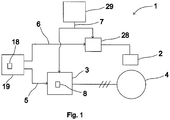
- Fig. 1 presents as a block diagram a braking apparatus 1, which comprises a machinery brake 2, and also an apparatus 3 for dynamic braking for braking an electric machine 4.
- the apparatus 3 for dynamic braking comprises a controller 8.
- the apparatus for dynamic braking also comprises controllable switches, which are connected between the stator windings of the electric machine.
- the controller 8 is fitted in connection with the control poles of the aforementioned controllable switches, for controlling the controllable switches with the switching reference formed by the controller 8.
- the controller closes the aforementioned switches connected between the stator windings of the electric machine, in which case the stator windings connect in short-circuit with each other.
- the apparatus 3 for dynamic braking and the movement management unit 19 of the electric machine are connected to each other with a serial communications bus, via which the movement management unit 19 of the electric machine and the controller 8 are connected together.
- the movement management unit 19 of the electric machine sends control parameters and also control signals 5, among others, to the controller 8 via the serial communications bus.
- the movement management unit 19 of the electric machine comprises a user panel 18, from the keyboard of which the control parameters can be entered.
- the controller 8 sends the status data of the apparatus for dynamic braking, among other things, to the movement management unit 19 of the electric machine via the serial communications bus.
- the status data can be read from the display of the user panel 18 of the movement management unit and a possible failure of the apparatus 3 for dynamic braking, among other things, can be deduced on the basis of the status data.
- the movement management unit 19 sends a starting signal 5 of the run to the controller 8, in which case the controller 8 switches its control mode and stops dynamic braking by opening the aforementioned switches connected between the stator windings of the electric machine.
- the movement management unit 19 also sends an opening signal 6 of the machinery brake to the control unit 28 of the machinery brake.
- the control unit 28 of the machinery brake controls the machinery brake 2 to open as a response to the opening signal of the machinery brake by supplying current to the magnetizing coil of the electromagnet of the machinery brake.
- the movement management unit 19 sends an end signal 5 of the run to the controller 8, in which case the controller again switches its control mode and activates dynamic braking by closing the aforementioned switches connected between the stator windings of the electric machine.
- the movement management unit 19 also sends an activation signal of the machinery brake to the control unit 28 of the machinery brake, as a response to which activation signal the control unit of the machinery brake activates the machinery brake to brake the movement of the electric machine by disconnecting the current supply to the magnetizing coil of the electromagnet of the machinery brake.
- the monitoring unit 29 of the electric drive monitors the operation of the electric drive and forms an emergency stop signal 7 when it detects a possible dangerous situation.
- Both the control unit 28 of the machinery brake and the controller 8 comprise an input for the emergency stop signal 7 formed by the monitoring unit 29 of the electric drive.
- the control unit 28 of the machinery brake activates the machinery brake 2 by disconnecting the current supply to the coil of the electromagnet of the machinery brake after it receives an emergency stop signal 7.
- the controller 8 When it receives an emergency stop signal the controller 8 switches into emergency stop mode.
- emergency stop mode the controller 8 activates the apparatus 3 for dynamic braking after a set activation delay of dynamic braking subsequent to receiving the emergency stop signal 7 such that the apparatus 3 for dynamic braking is activated after a delay with respect to the machinery brake 2.
- the controller 8 comprises an input for the speed data of the electric machine 4.
- the speed data of the electric machine 4 is determined by an encoder, which is mechanically in contact with a rotating part of the electric machine 4.
- the controller 8 also receives the speed reference of the electric machine 4, i.e. the target value of the speed of rotation of the electric machine, from the movement management unit 19.
- the movement management unit 19 sends the speed reference to the apparatus 3 for dynamic braking via the serial communications bus between the movement management unit 19 and the apparatus 3 for dynamic braking.
- the controller 8 determines the activation delay of dynamic braking on the basis of the speed data of the electric machine and the speed reference of the electric machine always using in the determination whichever of these that has the greater absolute value.
- the machinery brake 2 is activated after a certain activation delay of machinery braking.
- the activation delay is affected by, among other things, the disconnection time of the current of the coil of the electromagnet of the machinery brake 2 and also by the time it takes to engage the armature part to mechanically brake the movement of a rotating part of the electric machine 4.
- the speed of rotation of the electric machine 4 starts to decelerate such that after the activation delay of dynamic braking the speed of rotation has decelerated sufficiently in order to start dynamic braking.
- the controller 8 short-circuits the stator windings of the electric machine 4 in the manner described above.
- Fig. 4 illustrates some activation delays of machinery braking 16 and of dynamic braking 15.
- the machinery brake 2 is activated to brake the movement of the electric machine 4 after the activation delay 16 of machinery braking.
- the controller 8 activates the apparatus 3 for dynamic braking after the activation delay 15 of dynamic braking by short-circuiting the stator windings of the electric machine 4.
- the activation delay 15 of dynamic braking is longer than the activation delay 16 of machinery braking, in which case the apparatus 3 for dynamic braking is activated after a delay with respect to the machinery brake 2.
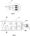
- Figs. 2a and 2b illustrate in more detail some apparatuses 3 for dynamic braking, which are also suited for use in connection with the embodiment of Fig. 1 .
- the apparatus 3 for dynamic braking of Fig. 2a comprises a contactor, the break contacts of which are connected between the stator windings of the electric machine 4.
- dynamic braking is always activated when current is not flowing in the control coil of the contactor.
- a current is supplied to the control coil of the contactor, as a result of which the contacts open and the short-circuit between the stator windings is disconnected.
- the apparatus 3 for dynamic braking of Fig. 2b is implemented with an inverter, with which variable amplitude and variable frequency current is also supplied to the electric machine 4 and thus the movement of the electric machine 4 is adjusted during normal operation of the electric machine.
- the controller 8 is fitted in connection with the control poles of the switches of the upper branch 14A of the inverter and/or of the lower branch 14B of the inverter, for switching the switches of only the lower branch 14B of the inverter, or alternatively of only the upper branch 14A of the inverter, with the switching reference of dynamic braking, which switching reference is formed by the controller 8. Dynamic braking can thus be performed, e.g.
- the apparatus for dynamic braking comprises a power source 22, the input of which is connected to the direct-current intermediate circuit 26 of the inverter.
- the output of the power source 22 is connected to the electricity supply of the controller 8, in which case the electrical energy produced during motor braking of the electric machine 4, i.e. in regenerative operation of the electric machine, 4 can be utilized as operating electricity of the controller 8.
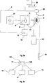
- Fig. 3a presents an elevator system, in which an elevator car 23 and a counterweight 30 are suspended in the elevator hoistway with elevator ropes, a belt or corresponding passing via the traction sheave of the hoisting machine 4.
- the torque moving the elevator car 23 is produced in the hoisting machine 4 with a permanent-magnet synchronous motor.
- Current supply from the electricity network 27 to the permanent-magnet synchronous motor occurs during normal operation of the elevator with a frequency converter.
- the frequency converter comprises an inverter, with which the voltage of the direct-current intermediate circuit of the frequency converter is changed to a variable frequency and variable amplitude supply voltage of the permanent-magnet synchronous motor.
- the frequency converter also comprises a network inverter-rectifier, with which the electrical energy produced during motor braking of the hoisting machine 4 is returned to the electricity network 27. Because the electrical energy produced during motor braking is returned to the electricity network 27, the power supply system of the hoisting machine is implemented without a separate braking resistor.
- a braking resistor refers to the type of power resistor, with which the electrical energy produced during motor braking is converted into heat instead of returning it to the electricity network.
- the braking apparatus of the elevator system of Fig. 3a comprises a machinery brake 2 and also an apparatus 3 for dynamic braking for braking the hoisting machine 4.
- the apparatus 3 for dynamic braking is implemented using the same inverter of the frequency converter, with which inverter current is also supplied to the permanent-magnet synchronous motor of the hoisting machine 4 during normal operation of the elevator.
- the controller 8 of dynamic braking is integrated into the control unit of the frequency converter, and it is here called a control part 8 of dynamic braking.
- the control part 8 of dynamic braking is fitted in connection with the control poles of the switches of the upper branch 14A of the inverter and/or of the lower branch 14B of the inverter, for switching the switches of only the lower branch 14B of the inverter, or alternatively of only the upper branch 14A of the inverter, with the switching reference of dynamic braking, which switching reference is formed by the control part 8.
- Dynamic braking can thus be performed, e.g. in the manner described in patent application EP 2062348 A1 such that the power supply from the direct-current intermediate circuit 26 of the inverter to the hoisting machine 4 is prevented during dynamic braking.
- the controllable switches of the inverter are preferably solid-state switches.
- the control part 8 switches into the activation mode of dynamic braking and it closes the aforementioned switches of the upper branch or the lower branch of the inverter, in which case the stator windings connect in short-circuit with each other.
- the hoisting machine 4 moves, e.g. owing to the imbalance of the net load of the elevator, a source voltage is induced in the short-circuited stator windings, which source voltage causes current, which current endeavors to brake the movement of the hoisting machine 4.
- Most of the electrical energy produced in dynamic braking in this case changes to heat in the winding resistances of the hoisting machine 4, and there is no need for a separate braking resistor.
- the frequency converter comprises a power source 22, the input of which is connected to the direct-current intermediate circuit 26 of the inverter.
- the output of the power source 22 is connected to the electricity supply of the control unit of the frequency converter, in which case the electrical energy produced during motor braking of the hoisting machine 4, i.e. in regenerative operation of the hoisting machine 4, can be utilized as operating electricity of the control unit. Since the rotor magnetization of the hoisting machine 4 is implemented with the permanent magnets of the permanent-magnet synchronous motor, source voltage is induced in the stator windings always when the hoisting machine 4 starts to rotate.
- dynamic braking can be started without an external energy source immediately when the source voltage of the stator has increased sufficiently to excite the power source 22, which after being excited starts to supply operating electricity to the control part 8 of dynamic braking.
- Dynamic braking can start after the electricity supply of the control part 8 has started.
- the frequency converter and the movement management unit 19 of the elevator car are connected to each other with a serial communications bus, via which the movement management unit 19 of the elevator car and the control part 8 of dynamic braking are connected together.
- the movement management unit 19 of the elevator car sends control parameters and also control signals 5, among other things, to the control part 8 of dynamic braking via the serial communications bus.
- the movement management unit 19 of the elevator car comprises a user panel 18, from the keyboard of which the control parameters can be entered.
- the user panel 18 is disposed on the stopping floor outside the elevator hoistway.
- the control part 8 of dynamic braking for its part, sends the status data of the apparatus 3 for dynamic braking, among other things, to the movement management unit 19 of the elevator car via the serial communications bus.
- the status data can be read from the display of the user panel 18 of the movement management unit and a possible failure of the apparatus 3 for dynamic braking, among other things, can be deduced on the basis of the status data.
- the movement management unit 19 of the elevator car sends a starting signal 5 of the run to the control part 8 of dynamic braking, in which case the control part 8 switches its control mode and stops dynamic braking by opening the aforementioned switches of the upper branch of the inverter or of the lower branch of the inverter.
- the movement management unit 19 of the elevator car also sends an opening signal 6 of the machinery brake to the control unit 28 of the machinery brake.
- the control unit 28 of the machinery brake controls the machinery brake 2 to open as a response to the opening signal 6 of the machinery brake by supplying current to the magnetizing coil of the electromagnet of the machinery brake.
- the movement management unit 19 of the elevator car sends an end signal 5 of the run to the control part 8 of dynamic braking, in which case the control part 8 again switches its control mode and activates dynamic braking by closing the aforementioned switches of the upper branch of the inverter or of the lower branch of the inverter.
- the movement management unit 19 of the elevator car also sends an activation signal 6 of the machinery brake to the control unit 28 of the machinery brake, as a response to which activation signal the control unit of the machinery brake activates the machinery brake to brake the movement of the hoisting machine 4 by disconnecting the current supply to the magnetizing coil of the electromagnet of the machinery brake.
- the safety circuit 29 of the elevator monitors the operation of the elevator system and forms an emergency stop signal 7 when it detects a possible dangerous situation.
- Both the control unit 28 of the machinery brake and the control part 8 of dynamic braking comprise an input for the emergency stop signal 7 formed by the safety circuit 29 of the elevator.
- the control unit 28 of the machinery brake activates the machinery brake 2 by disconnecting the current supply to the coil of the electromagnet of the machinery brake after it receives an emergency stop signal 7.
- the control part 8 of dynamic braking When it receives an emergency stop signal the control part 8 of dynamic braking switches into emergency stop mode.
- the control part 8 of dynamic braking activates dynamic braking after a set activation delay of dynamic braking subsequent to receiving an emergency stop signal 7 such that dynamic braking is activated after a delay with respect to the machinery brake 2.
- the control part 8 of dynamic braking comprises an input for the speed data 17 of the hoisting machine 4.
- the speed data 17 of the hoisting machine 4 is determined by an encoder, which is mechanically in contact with the rotating part of the hoisting machine 4.
- the control part 8 of dynamic braking also receives the speed reference of the hoisting machine 4, i.e.
- the movement management unit 19 sends the speed reference to the control part 8 of dynamic braking via the serial communications bus between the movement control unit 19 and the frequency converter.
- the control part 8 of dynamic braking determines the activation delay of dynamic braking on the basis of the speed data of the hoisting machine and the speed reference of the hoisting machine, always using in the determination whichever of these that has the greater absolute value.
- the machinery brake 2 is activated after a certain activation delay of machinery braking.
- the activation delay of machinery braking is affected by, among other things, the disconnection time of the current of the coil of the electromagnet of the machinery brake 2 and also by the time it takes to engage the armature part to mechanically brake the movement of a rotating part of the hoisting machine 4.
- the speed of rotation of the hoisting machine 4 starts to decelerate such that after the activation delay of dynamic braking the speed of rotation has decelerated sufficiently in order to start dynamic braking.
- control part 8 of dynamic braking short-circuits the stator windings of the hoisting machine 4 in the manner described above. Because the source voltage induced in the stator windings of the hoisting machine 4 is proportional to the speed of rotation, reducing the speed of rotation also affects the short-circuit current flowing in the stator windings at the starting moment of dynamic braking such that the short-circuit current decreases as the speed of rotation decreases.
- the dynamic braking function is temporarily removed from use. Removal from use occurs by supplying a parameter that refers to prevention mode of dynamic braking to the control part 8 of dynamic braking via the user panel 18 of the movement management unit of the elevator car. In this case when it receives the parameter the control part 8 of dynamic braking switches into prevention mode of dynamic braking.
- the control part 8 of dynamic braking switches from prevention mode of dynamic braking back into normal mode of dynamic braking as an alternative when it detects the initiation of the next run of the elevator; thus prevention mode of dynamic braking is only in use during the time between runs, e.g. when the elevator car is allowed to move by opening the machinery brake manually.
- the control part 8 of dynamic braking switches from prevention mode of dynamic braking into normal mode of dynamic braking also when it receives a parameter that refers to normal mode of dynamic braking from the user panel 18 and also when it detects a communication break in the serial communications between the user panel 18 and the frequency converter. With this it can be ensured that the dynamic braking function is returned back to use always after performing machinery brake tests/safety gear tests.
- Fig. 3b illustrates e.g. the control modes of the controller 8 of the apparatus for dynamic braking according to any of the preceding embodiments.
- dynamic braking is either activated 12A or switched off 12B such that the activation and switching off of dynamic braking are selected on the basis of the control signal of the braking apparatus.
- the controller 8 switches from normal mode 12 into emergency stop mode 10, in which case dynamic braking is activated after a delay with respect to the machinery brake, e.g. such as is described in any of the preceding embodiments.
- the controller 8 switches from normal mode 12 into prevention mode 11 of dynamic braking when it receives a parameter that refers to prevention mode of dynamic braking, e.g. in the manner presented in the embodiment of Fig. 3a . If a failure is detected in the apparatus for dynamic braking, the controller switches into fault mode 13. In one embodiment of the invention, the controller 8 also sends information about the fault to the user interface 18.
Landscapes
- Engineering & Computer Science (AREA)
- Automation & Control Theory (AREA)
- Stopping Of Electric Motors (AREA)
- Elevator Control (AREA)
Description
- The invention relates to solutions for braking an electric machine, and more particularly to braking apparatuses and electric drives of elevator systems for braking the electric machine.
- Safe operation of an elevator system in the event of a malfunction, such as an electricity outage, is ensured with the machinery brake of a hoisting machine. In addition, so-called dynamic braking is often used in elevator hoisting machines, in which case the windings of the hoisting machine are short-circuited with dynamic braking switches, e.g. during a standstill of an elevator. Racing of the hoisting machine can be prevented with a short-circuit of the windings because when the hoisting machine moves the source voltage induced in the short-circuited windings produces a current that endeavors to brake the movement of the hoisting machine. Most of the electrical energy produced in dynamic braking in this case is converted to heat in the winding resistances of the hoisting machine. A dynamic braking apparatus is for example shown in documents
JP 2007 223799 A US 5,070,290 A , activating the same upon receiving a signal of power failure to control the braking process in control modes referred to the prevailing situation. - Instead of short-circuiting the windings, the electrical energy produced in dynamic braking can also be supplied to a load outside the hoisting machine, such as to a power resistor. In this way heating of the hoisting machine can be reduced during dynamic braking. The power resistor needed is, however, generally rather large in size; in addition, a free space must be reserved around it owing to the strong heat rise occurring in the resistor.
- The contacts of a contactor, for instance, can be used as switches of dynamic braking. In certain exceptional situations, such as in connection with brake tests, the dynamic braking function must be temporarily removed from use. Sometimes the function is removed from use by detaching the contacts of the contactors of dynamic braking from the supply cables of the hoisting machine. In this case there is a danger that it is forgotten to re-connect the contacts of the contactors of dynamic braking after the tests have been performed. Without dynamic braking, an elevator car may race when the brake is left free, so forgetting the re-connection of the contacts of the contactors of dynamic braking may cause a dangerous situation to a serviceman working in the elevator hoistway.
- Instead of the contacts of the contactors also the solid-state switches of an inverter controlling the hoisting machine, can be used as switches of dynamic braking. A substantially high current may flow in the solid-state switches during dynamic braking. The current causes considerable warming in the power semiconductors, which again could shorten the service life of the inverter. For this reason, the current stress caused to the solid-state switches by dynamic braking must also be taken into consideration when dimensioning the inverter.
- Further, document
US 4,074,176 discloses that flashover protection in trains, cars, trucks and elevators can be achieved by applying both mechanical and dynamic braking at the same time or by interrupting dynamic braking and substituting mechanical braking therefor so to prevent damage to the motor by excessive dynamic braking voltages. - Owing to the aforementioned reasons, among others, the invention discloses an elevator system with an improved braking apparatus and electric drive according to
main claim 1. The aim of the invention is also e.g. to improve the safety of the braking apparatus, electric drive and elevator system and also to improve the reliability of the apparatus for dynamic braking. - In relation to the characteristic attributes of the invention, reference is made to the claims.
- Part of the inventive elevator system is a braking apparatus comprising an apparatus for dynamic braking, for braking the electric machine with dynamic braking, an input for a control signal of the braking apparatus, and also a controller for controlling the apparatus for dynamic braking as a response to the aforementioned control signal of the braking apparatus. The aforementioned controller comprises control modes for controlling the apparatus for dynamic braking according to the control mode to be used at any given time. In this case the apparatus for dynamic braking can be controlled in a different way in different operating situations, such as during normal operation of the electric machine, and also in connection with an operational non-conformance or dangerous situation. The aforementioned controller can comprise a microprocessor and the aforementioned control modes can be implemented in a manner specified in the software of the microprocessor.
- According to one or more embodiments the control mode to be used is selected on the basis of the control signal of the braking apparatus. In this case the control mode can be selected, e.g. on the basis of the control signal of normal drive or on the basis of the control signal of service drive. The control mode can also be selected e.g. on the basis of the status data of the safety circuit of the elevator.
- According to one or more embodiments the braking apparatus comprises a machinery brake for braking the electric machine. One control signal of the braking apparatus is an emergency stop signal, and the controller is arranged to activate the apparatus for dynamic braking after a delay with respect to the machinery brake in an emergency stop situation. In this case, when the machinery brake is activated it engages to brake the movement of the electric machine before the apparatus for dynamic braking is activated. If the machinery brake functions normally, the movement of the electric machine starts to decelerate after the machinery brake has been activated. The speed of the electric machine has thus had time to decelerate before dynamic braking starts. When the speed of the electric machine decelerates, the current stress of the switch/switches of dynamic braking decreases, which lengthens the lifetime of the switches and thus improves the reliability of the apparatus for dynamic braking. If the machinery brake is defective and the speed of the electric machine has not considerably decelerated when dynamic braking starts, high current stress is exerted on the switch/switches of dynamic braking; in this case what is more essential than the current stress of the switches of dynamic braking is, however, that the movement of the electric machine can be braked with the apparatus for dynamic braking also in a fault situation of the machinery brake, and thus the safety of the emergency stop can be improved.
- According to one or more embodiments, the apparatus for dynamic braking comprises a controllable switch and the controller is fitted in connection with the control pole of the aforementioned controllable switch, for controlling the controllable switch with a switching reference formed by the controller. Thus the current of dynamic braking can also possibly be adjusted during dynamic braking.
- According to one or more embodiments, the controller is arranged to activate the apparatus for dynamic braking after a set activation delay of dynamic braking subsequent to receiving an emergency stop signal.
- According to one or more embodiments, the machinery brake is arranged to be activated after a certain activation delay of machinery braking subsequent to receiving an emergency stop signal, and the aforementioned activation delay of dynamic braking is set to be longer than the activation delay of machinery braking. In this case after an activation delay of machinery braking, the machinery brake engages to brake the movement of the electric machine before the activation of the apparatus for dynamic braking, which activation occurs after the activation delay of dynamic braking. If the machinery brake functions normally the movement of the electric machine starts to decelerate after the machinery brake is activated. The speed of the electric machine has thus had time to decelerate before dynamic braking starts. When the speed of the electric machine decelerates, the current stress of the switch/switches of dynamic braking decreases, which lengthens the lifetime of the switches and thus improves the reliability of the apparatus for dynamic braking. If the machinery brake is defective and the speed of the electric machine has not considerably decelerated when dynamic braking starts, high current stress is exerted on the switch/switches of dynamic braking; in this case what is more essential than the current stress of the switches of dynamic braking is, however, that the movement of the electric machine can be braked with the apparatus for dynamic braking also in a fault situation of the machinery brake, and thus the safety of the emergency stop can be improved.
- According to one or more embodiments, the controller comprises an input for the speed data of the electric machine and the activation delay of dynamic braking is determined on the basis of the speed data of the electric machine. In this case the activation delay of dynamic braking can be determined, e.g. such that the higher the speed of the electric machine is when the activation signal arrives at the braking apparatus, the longer is the activation delay of dynamic braking. The longer the activation delay of dynamic braking is, the more the machinery brake has time to decelerate the speed of the electric machine before dynamic braking starts.
- According to one or more embodiments, the controller comprises a bus for receiving the speed reference of the electric machine and the activation delay of dynamic braking is determined on the basis of the speed data of the electric machine or on the basis of the speed reference of the electric machine, always using in the determination whichever of these that has the greater absolute value. For instance, a pulse encoder measuring the movement of the electric machine may malfunction such that the pulses of the encoder signal completely cease to travel, in which case the speed data indicated by the encoder signal goes to zero. If the activation delay is determined from the speed reference of the electric machine, the activation delay can thus be determined irrespective of the defect of the encoder or of another motion measurement sensor.
- According to the invention, the braking apparatus comprises a user interface.
- According to one or more embodiments of the invention, the controller comprises a memory, and a data transfer connection is made between the user interface and the controller, for recording the control parameter of dynamic braking to be supplied from the user interface into the memory of the controller. In this case the control parameters of dynamic braking can be changed for each specific use, which improves the functionality of dynamic braking; in one embodiment of the invention the controller can also send the status data of the apparatus for dynamic braking to the user interface, which facilitates e.g. troubleshooting of the apparatus for dynamic braking.
- According to the invention, the control parameter of dynamic braking refers to at least one of the following: prevention mode of dynamic braking, normal mode of dynamic braking, nominal speed of the electric machine, average deceleration of the electric machine with machinery braking, status data of the apparatus for dynamic braking. Thus the operation of the apparatus for dynamic braking can be temporarily prevented via the user interface by sending a control parameter that refers to prevention mode of dynamic braking from the user interface to the controller. Prevention mode of dynamic braking can again be removed and dynamic braking can be taken into use by sending a control parameter that refers to normal mode of dynamic braking from the user interface to the controller. The activation delay of dynamic braking can be set as proportional to the nominal speed of the electric machine such that the activation delay shortens as the speed of the electric machine falls below the nominal speed and the activation delay increases as the speed of the electric machine increases above the nominal speed.
- In one embodiment of the invention the activation delay t is defined by means of the instantaneous speed v of the electric machine and by means of the average deceleration of the electric machine with machinery braking a from the equation:

- The average deceleration of the electric machine with machinery braking a is preferably given the value of approx. 1m/s^2.
- According to one or more embodiments of the invention, the braking apparatus comprises a machinery brake for braking the electric machine, an apparatus for dynamic braking, for braking the electric machine with dynamic braking, and also an input for an emergency stop signal. Both the machinery brake and the apparatus for dynamic braking are arranged to be activated as a response to the aforementioned emergency stop signal such that the apparatus for dynamic braking is arranged to be activated after a delay with respect to the machinery brake.
- According to one or more embodiments, the electric drive comprises a permanent-magnet synchronous motor. The permanent magnets in the rotor of the permanent-magnet synchronous motor induce a voltage in the stator windings immediately when the rotor starts moving. In one embodiment of the invention the aforementioned voltage induced in the stator windings of the permanent magnets is utilized in the electricity supply of the controller, in which case dynamic braking can start after the speed of the rotor, and thus the voltage induced in the stator windings, have increased sufficiently in order to produce the operating electricity needed by the controller. In this case dynamic braking can be performed without an external energy source, such as without an electricity network or accumulator.
- According to one or more embodiments, the electric drive comprises a frequency converter to be connected to the electric machine for driving the electric machine, and the frequency converter comprises an inverter, for supplying variable amplitude and variable frequency current to the electric machine.
- According to one or more embodiments, the controller is fitted in connection with the control poles of the switches of the upper branch of the inverter and/or of the lower branch of the inverter, for switching the switches of only the lower branch of the inverter, or alternatively of only the upper branch of the inverter, with the switching reference of dynamic braking, which switching reference is formed by the controller. Dynamic braking can thus be performed, e.g. in the manner described in patent application
EP 2062348 A1 , such that the power supply from the direct-current intermediate circuit of the inverter to the electric machine is prevented during dynamic braking. - According to one or more embodiments, the apparatus for dynamic braking is arranged to short-circuit the excitation windings of the electric machine, for dynamic braking of the electric machine. Most of the electrical energy produced in dynamic braking is in this case converted to heat in the winding resistances of the electric machine, and no separate load, such as a power resistor, is needed to consume the electrical energy produced in the braking.
- According to one or more embodiments, the electric drive is implemented without a braking resistor.
- According to one or more embodiments, the frequency converter comprises a network inverter-rectifier, for supplying the electrical energy produced in regenerative operation of the electric machine to the electricity network. When dynamic braking is in this case performed by short-circuiting the excitation windings of the electric machine and by consuming most of the electrical energy produced in dynamic braking in the winding resistances of the electric machine, the power supply appliance of the electric machine can be implemented without a separate power resistor, which simplifies the power supply appliance and reduces the space requirement of the power supply appliance.
- According to one or more embodiments, the frequency converter comprises a direct-current intermediate circuit, and the electric drive comprises a power source, the input of which is connected to the direct-current intermediate circuit of the frequency converter, and the output of which power source is connected to the electricity supply of the controller, for utilizing the electrical energy produced in regenerative operation of the electric machine as operating electricity of the controller. The voltage induced in the stator windings of the moving rotor of the electric machine can in this case also be utilized in the electricity supply of the controller, in which case dynamic braking can start after the speed of the rotor and thus the voltage induced in the stator windings have increased sufficiently in order to produce the operating electricity needed by the controller. In this case dynamic braking can also be performed, if necessary, without an external energy source, such as without an electricity network or accumulator.
- According to one or more embodiments, the elevator hoisting machine and the frequency converter are fitted in an elevator hoistway. In these types of elevator systems without machine room a large part of the servicing work of the elevator occurs in the elevator hoistway. By means of an elevator system according to the invention, working safety in the elevator hoistway can be improved.
- According to one or more embodiments, the aforementioned user interface is fitted outside the elevator hoistway. In this case the control parameters of dynamic braking can be changed from outside the elevator hoistway, e.g. from the stopping floor. In one embodiment of the invention also the diagnostics data, such as the status data of the apparatus for dynamic braking can be read using the same user interface.
- According to the invention, the controller is arranged to switch into prevention mode of dynamic braking when the controller receives a parameter that refers to prevention mode of dynamic braking from the user interface, and the controller is arranged to switch from prevention mode of dynamic braking into normal mode of dynamic braking when it detects at least one of the following:
- the controller detects the initiation of the next elevator run
- the controller receives a parameter that refers to normal mode of dynamic braking from the user interface
- the controller detects a communication break in the data transfer connection between the user interface and the controller.
- In this way it can be ensured that the dynamic braking function is certain to return to use after being temporarily removed from use.
- The aforementioned summary, as well as the additional features and advantages of the invention presented below, will be better understood by the aid of the following description of some embodiments, said description not limiting the scope of application of the invention.
-
- Fig. 1
- presents a braking apparatus as a block diagram
- Fig. 2a
- illustrates an apparatus for dynamic braking as included in the invention
- Fig. 2b
- illustrates a second apparatus for dynamic braking as included in the invention
- Fig. 3a
- presents an elevator system according to the invention as a block diagram
- Fig. 3b
- presents possible control modes of the controller according to the invention as a status chart
- Fig. 4
- illustrates an activation delay of machinery braking and also an activation delay of dynamic braking
-
Fig. 1 presents as a block diagram abraking apparatus 1, which comprises amachinery brake 2, and also anapparatus 3 for dynamic braking for braking anelectric machine 4. Theapparatus 3 for dynamic braking comprises acontroller 8. The apparatus for dynamic braking also comprises controllable switches, which are connected between the stator windings of the electric machine. Thecontroller 8 is fitted in connection with the control poles of the aforementioned controllable switches, for controlling the controllable switches with the switching reference formed by thecontroller 8. When dynamic braking is activated, the controller closes the aforementioned switches connected between the stator windings of the electric machine, in which case the stator windings connect in short-circuit with each other. When the electric machine moves, a source voltage is induced in the short-circuited stator windings, which source voltage causes current, which current endeavors to brake the movement of the electric machine. Most of the electrical energy produced in dynamic braking in this case changes to heat in the winding resistances of the electric machine. - The
apparatus 3 for dynamic braking and themovement management unit 19 of the electric machine are connected to each other with a serial communications bus, via which themovement management unit 19 of the electric machine and thecontroller 8 are connected together. Themovement management unit 19 of the electric machine sends control parameters and also controlsignals 5, among others, to thecontroller 8 via the serial communications bus. Themovement management unit 19 of the electric machine comprises auser panel 18, from the keyboard of which the control parameters can be entered. Thecontroller 8, on the other hand, sends the status data of the apparatus for dynamic braking, among other things, to themovement management unit 19 of the electric machine via the serial communications bus. The status data can be read from the display of theuser panel 18 of the movement management unit and a possible failure of theapparatus 3 for dynamic braking, among other things, can be deduced on the basis of the status data. - The
movement management unit 19 sends a startingsignal 5 of the run to thecontroller 8, in which case thecontroller 8 switches its control mode and stops dynamic braking by opening the aforementioned switches connected between the stator windings of the electric machine. At the same time themovement management unit 19 also sends anopening signal 6 of the machinery brake to thecontrol unit 28 of the machinery brake. Thecontrol unit 28 of the machinery brake controls themachinery brake 2 to open as a response to the opening signal of the machinery brake by supplying current to the magnetizing coil of the electromagnet of the machinery brake. At the end of the run, themovement management unit 19 sends anend signal 5 of the run to thecontroller 8, in which case the controller again switches its control mode and activates dynamic braking by closing the aforementioned switches connected between the stator windings of the electric machine. Themovement management unit 19 also sends an activation signal of the machinery brake to thecontrol unit 28 of the machinery brake, as a response to which activation signal the control unit of the machinery brake activates the machinery brake to brake the movement of the electric machine by disconnecting the current supply to the magnetizing coil of the electromagnet of the machinery brake. - The
monitoring unit 29 of the electric drive monitors the operation of the electric drive and forms anemergency stop signal 7 when it detects a possible dangerous situation. Both thecontrol unit 28 of the machinery brake and thecontroller 8 comprise an input for theemergency stop signal 7 formed by themonitoring unit 29 of the electric drive. Thecontrol unit 28 of the machinery brake activates themachinery brake 2 by disconnecting the current supply to the coil of the electromagnet of the machinery brake after it receives anemergency stop signal 7. - When it receives an emergency stop signal the
controller 8 switches into emergency stop mode. In emergency stop mode thecontroller 8 activates theapparatus 3 for dynamic braking after a set activation delay of dynamic braking subsequent to receiving theemergency stop signal 7 such that theapparatus 3 for dynamic braking is activated after a delay with respect to themachinery brake 2. Thecontroller 8 comprises an input for the speed data of theelectric machine 4. The speed data of theelectric machine 4 is determined by an encoder, which is mechanically in contact with a rotating part of theelectric machine 4. Thecontroller 8 also receives the speed reference of theelectric machine 4, i.e. the target value of the speed of rotation of the electric machine, from themovement management unit 19. Themovement management unit 19 sends the speed reference to theapparatus 3 for dynamic braking via the serial communications bus between themovement management unit 19 and theapparatus 3 for dynamic braking. Thecontroller 8 determines the activation delay of dynamic braking on the basis of the speed data of the electric machine and the speed reference of the electric machine always using in the determination whichever of these that has the greater absolute value. The activation delay t of dynamic braking is defined by means of the instantaneous speed / speed reference v of the electric machine and also by means of the average deceleration with machinery braking a from the equation:
- In this case the higher the speed of rotation v of the electric machine is when the
controller 8 receives anemergency stop signal 7, the longer is the activation delay of dynamic braking. - The
machinery brake 2 is activated after a certain activation delay of machinery braking. The activation delay is affected by, among other things, the disconnection time of the current of the coil of the electromagnet of themachinery brake 2 and also by the time it takes to engage the armature part to mechanically brake the movement of a rotating part of theelectric machine 4. After the armature part is engaged to mechanically brake the movement of the rotating part of theelectric machine 4, and thus after the machinery brake is activated, the speed of rotation of theelectric machine 4 starts to decelerate such that after the activation delay of dynamic braking the speed of rotation has decelerated sufficiently in order to start dynamic braking. In this case thecontroller 8 short-circuits the stator windings of theelectric machine 4 in the manner described above. Because the source voltage induced in the stator windings of theelectric machine 4 is proportional to the speed of rotation, reducing the speed of rotation also affects the short-circuit current flowing in the stator windings at the starting moment of dynamic braking such that the short-circuit current decreases as the speed of rotation decreases.Fig. 4 illustrates some activation delays ofmachinery braking 16 and ofdynamic braking 15. At the moment t = 0 thecontrol unit 28 of the machinery brake and thecontroller 8 receive an emergency stop signal. Themachinery brake 2 is activated to brake the movement of theelectric machine 4 after theactivation delay 16 of machinery braking. Thecontroller 8 activates theapparatus 3 for dynamic braking after theactivation delay 15 of dynamic braking by short-circuiting the stator windings of theelectric machine 4. According toFig. 4 , theactivation delay 15 of dynamic braking is longer than theactivation delay 16 of machinery braking, in which case theapparatus 3 for dynamic braking is activated after a delay with respect to themachinery brake 2. -
Figs. 2a and 2b illustrate in more detail someapparatuses 3 for dynamic braking, which are also suited for use in connection with the embodiment ofFig. 1 . - The
apparatus 3 for dynamic braking ofFig. 2a comprises a contactor, the break contacts of which are connected between the stator windings of theelectric machine 4. In this case dynamic braking is always activated when current is not flowing in the control coil of the contactor. To stop dynamic braking a current is supplied to the control coil of the contactor, as a result of which the contacts open and the short-circuit between the stator windings is disconnected. - The
apparatus 3 for dynamic braking ofFig. 2b is implemented with an inverter, with which variable amplitude and variable frequency current is also supplied to theelectric machine 4 and thus the movement of theelectric machine 4 is adjusted during normal operation of the electric machine. Thecontroller 8 is fitted in connection with the control poles of the switches of theupper branch 14A of the inverter and/or of thelower branch 14B of the inverter, for switching the switches of only thelower branch 14B of the inverter, or alternatively of only theupper branch 14A of the inverter, with the switching reference of dynamic braking, which switching reference is formed by thecontroller 8. Dynamic braking can thus be performed, e.g. in the manner described in patent applicationEP 2062348 A1 such that the power supply from the direct-currentintermediate circuit 26 of the inverter to theelectric machine 4 is prevented during dynamic braking. The aforementioned switches of the inverter are preferably solid-state switches, such as IGBT transistors, MOSFET transistors or corresponding. According toFig. 2b the apparatus for dynamic braking comprises apower source 22, the input of which is connected to the direct-currentintermediate circuit 26 of the inverter. The output of thepower source 22 is connected to the electricity supply of thecontroller 8, in which case the electrical energy produced during motor braking of theelectric machine 4, i.e. in regenerative operation of the electric machine, 4 can be utilized as operating electricity of thecontroller 8. -
Fig. 3a presents an elevator system, in which anelevator car 23 and acounterweight 30 are suspended in the elevator hoistway with elevator ropes, a belt or corresponding passing via the traction sheave of the hoistingmachine 4. The torque moving theelevator car 23 is produced in the hoistingmachine 4 with a permanent-magnet synchronous motor. Current supply from theelectricity network 27 to the permanent-magnet synchronous motor occurs during normal operation of the elevator with a frequency converter. The frequency converter comprises an inverter, with which the voltage of the direct-current intermediate circuit of the frequency converter is changed to a variable frequency and variable amplitude supply voltage of the permanent-magnet synchronous motor. The frequency converter also comprises a network inverter-rectifier, with which the electrical energy produced during motor braking of the hoistingmachine 4 is returned to theelectricity network 27. Because the electrical energy produced during motor braking is returned to theelectricity network 27, the power supply system of the hoisting machine is implemented without a separate braking resistor. A braking resistor refers to the type of power resistor, with which the electrical energy produced during motor braking is converted into heat instead of returning it to the electricity network. - The braking apparatus of the elevator system of
Fig. 3a comprises amachinery brake 2 and also anapparatus 3 for dynamic braking for braking the hoistingmachine 4. Theapparatus 3 for dynamic braking is implemented using the same inverter of the frequency converter, with which inverter current is also supplied to the permanent-magnet synchronous motor of the hoistingmachine 4 during normal operation of the elevator. Thecontroller 8 of dynamic braking is integrated into the control unit of the frequency converter, and it is here called acontrol part 8 of dynamic braking. Thecontrol part 8 of dynamic braking is fitted in connection with the control poles of the switches of theupper branch 14A of the inverter and/or of thelower branch 14B of the inverter, for switching the switches of only thelower branch 14B of the inverter, or alternatively of only theupper branch 14A of the inverter, with the switching reference of dynamic braking, which switching reference is formed by thecontrol part 8. Dynamic braking can thus be performed, e.g. in the manner described in patent applicationEP 2062348 A1 such that the power supply from the direct-currentintermediate circuit 26 of the inverter to the hoistingmachine 4 is prevented during dynamic braking. The controllable switches of the inverter are preferably solid-state switches. - When dynamic braking is activated the
control part 8 switches into the activation mode of dynamic braking and it closes the aforementioned switches of the upper branch or the lower branch of the inverter, in which case the stator windings connect in short-circuit with each other. When the hoistingmachine 4 moves, e.g. owing to the imbalance of the net load of the elevator, a source voltage is induced in the short-circuited stator windings, which source voltage causes current, which current endeavors to brake the movement of the hoistingmachine 4. Most of the electrical energy produced in dynamic braking in this case changes to heat in the winding resistances of the hoistingmachine 4, and there is no need for a separate braking resistor. - The frequency converter comprises a
power source 22, the input of which is connected to the direct-currentintermediate circuit 26 of the inverter. The output of thepower source 22 is connected to the electricity supply of the control unit of the frequency converter, in which case the electrical energy produced during motor braking of the hoistingmachine 4, i.e. in regenerative operation of the hoistingmachine 4, can be utilized as operating electricity of the control unit. Since the rotor magnetization of the hoistingmachine 4 is implemented with the permanent magnets of the permanent-magnet synchronous motor, source voltage is induced in the stator windings always when the hoistingmachine 4 starts to rotate. In this case dynamic braking can be started without an external energy source immediately when the source voltage of the stator has increased sufficiently to excite thepower source 22, which after being excited starts to supply operating electricity to thecontrol part 8 of dynamic braking. Dynamic braking can start after the electricity supply of thecontrol part 8 has started. - The frequency converter and the
movement management unit 19 of the elevator car are connected to each other with a serial communications bus, via which themovement management unit 19 of the elevator car and thecontrol part 8 of dynamic braking are connected together. Themovement management unit 19 of the elevator car sends control parameters and also controlsignals 5, among other things, to thecontrol part 8 of dynamic braking via the serial communications bus. Themovement management unit 19 of the elevator car comprises auser panel 18, from the keyboard of which the control parameters can be entered. Theuser panel 18 is disposed on the stopping floor outside the elevator hoistway. Thecontrol part 8 of dynamic braking, for its part, sends the status data of theapparatus 3 for dynamic braking, among other things, to themovement management unit 19 of the elevator car via the serial communications bus. The status data can be read from the display of theuser panel 18 of the movement management unit and a possible failure of theapparatus 3 for dynamic braking, among other things, can be deduced on the basis of the status data. - The
movement management unit 19 of the elevator car sends a startingsignal 5 of the run to thecontrol part 8 of dynamic braking, in which case thecontrol part 8 switches its control mode and stops dynamic braking by opening the aforementioned switches of the upper branch of the inverter or of the lower branch of the inverter. At the same time themovement management unit 19 of the elevator car also sends anopening signal 6 of the machinery brake to thecontrol unit 28 of the machinery brake. Thecontrol unit 28 of the machinery brake controls themachinery brake 2 to open as a response to theopening signal 6 of the machinery brake by supplying current to the magnetizing coil of the electromagnet of the machinery brake. At the end of the run themovement management unit 19 of the elevator car sends anend signal 5 of the run to thecontrol part 8 of dynamic braking, in which case thecontrol part 8 again switches its control mode and activates dynamic braking by closing the aforementioned switches of the upper branch of the inverter or of the lower branch of the inverter. Themovement management unit 19 of the elevator car also sends anactivation signal 6 of the machinery brake to thecontrol unit 28 of the machinery brake, as a response to which activation signal the control unit of the machinery brake activates the machinery brake to brake the movement of the hoistingmachine 4 by disconnecting the current supply to the magnetizing coil of the electromagnet of the machinery brake. - The
safety circuit 29 of the elevator monitors the operation of the elevator system and forms anemergency stop signal 7 when it detects a possible dangerous situation. Both thecontrol unit 28 of the machinery brake and thecontrol part 8 of dynamic braking comprise an input for theemergency stop signal 7 formed by thesafety circuit 29 of the elevator. Thecontrol unit 28 of the machinery brake activates themachinery brake 2 by disconnecting the current supply to the coil of the electromagnet of the machinery brake after it receives anemergency stop signal 7. - When it receives an emergency stop signal the
control part 8 of dynamic braking switches into emergency stop mode. Thecontrol part 8 of dynamic braking activates dynamic braking after a set activation delay of dynamic braking subsequent to receiving anemergency stop signal 7 such that dynamic braking is activated after a delay with respect to themachinery brake 2. Thecontrol part 8 of dynamic braking comprises an input for thespeed data 17 of the hoistingmachine 4. Thespeed data 17 of the hoistingmachine 4 is determined by an encoder, which is mechanically in contact with the rotating part of the hoistingmachine 4. Thecontrol part 8 of dynamic braking also receives the speed reference of the hoistingmachine 4, i.e. the speed of rotation of the hoisting machine, and thus also the target value of the speed of theelevator car 23, from themovement management unit 19 of the elevator car. Themovement management unit 19 sends the speed reference to thecontrol part 8 of dynamic braking via the serial communications bus between themovement control unit 19 and the frequency converter. Thecontrol part 8 of dynamic braking determines the activation delay of dynamic braking on the basis of the speed data of the hoisting machine and the speed reference of the hoisting machine, always using in the determination whichever of these that has the greater absolute value. The activation delay t of dynamic braking is defined by means of the instantaneous speed/speed reference v of the hoisting machine and by means of the average deceleration with machinery braking a from the equation:
- In this case the higher the speed of rotation v of the hoisting machine is when the
control part 8 of dynamic braking receives anemergency stop signal 7, the longer is the activation delay of dynamic braking. - The
machinery brake 2 is activated after a certain activation delay of machinery braking. The activation delay of machinery braking is affected by, among other things, the disconnection time of the current of the coil of the electromagnet of themachinery brake 2 and also by the time it takes to engage the armature part to mechanically brake the movement of a rotating part of the hoistingmachine 4. After the armature part is engaged to mechanically brake the movement of the rotating part of the hoistingmachine 4, and thus after the machinery brake is activated, the speed of rotation of the hoistingmachine 4 starts to decelerate such that after the activation delay of dynamic braking the speed of rotation has decelerated sufficiently in order to start dynamic braking. In this case thecontrol part 8 of dynamic braking short-circuits the stator windings of the hoistingmachine 4 in the manner described above. Because the source voltage induced in the stator windings of the hoistingmachine 4 is proportional to the speed of rotation, reducing the speed of rotation also affects the short-circuit current flowing in the stator windings at the starting moment of dynamic braking such that the short-circuit current decreases as the speed of rotation decreases. - For example, in connection with machinery brake tests of a hoisting machine and/or safety gear tests of an elevator car, the dynamic braking function is temporarily removed from use. Removal from use occurs by supplying a parameter that refers to prevention mode of dynamic braking to the
control part 8 of dynamic braking via theuser panel 18 of the movement management unit of the elevator car. In this case when it receives the parameter thecontrol part 8 of dynamic braking switches into prevention mode of dynamic braking. Thecontrol part 8 of dynamic braking switches from prevention mode of dynamic braking back into normal mode of dynamic braking as an alternative when it detects the initiation of the next run of the elevator; thus prevention mode of dynamic braking is only in use during the time between runs, e.g. when the elevator car is allowed to move by opening the machinery brake manually. Thecontrol part 8 of dynamic braking switches from prevention mode of dynamic braking into normal mode of dynamic braking also when it receives a parameter that refers to normal mode of dynamic braking from theuser panel 18 and also when it detects a communication break in the serial communications between theuser panel 18 and the frequency converter. With this it can be ensured that the dynamic braking function is returned back to use always after performing machinery brake tests/safety gear tests. -
Fig. 3b illustrates e.g. the control modes of thecontroller 8 of the apparatus for dynamic braking according to any of the preceding embodiments. Duringnormal mode 12 of dynamic braking, dynamic braking is either activated 12A or switched off 12B such that the activation and switching off of dynamic braking are selected on the basis of the control signal of the braking apparatus. When it receives an emergency stop signal thecontroller 8 switches fromnormal mode 12 intoemergency stop mode 10, in which case dynamic braking is activated after a delay with respect to the machinery brake, e.g. such as is described in any of the preceding embodiments. Thecontroller 8 switches fromnormal mode 12 intoprevention mode 11 of dynamic braking when it receives a parameter that refers to prevention mode of dynamic braking, e.g. in the manner presented in the embodiment ofFig. 3a . If a failure is detected in the apparatus for dynamic braking, the controller switches intofault mode 13. In one embodiment of the invention, thecontroller 8 also sends information about the fault to theuser interface 18. - In the preceding the invention is described in connection with an elevator system with counterweight; the solution according to the invention is suited, however, also to elevator systems without counterweight.
- The invention is not limited solely to the embodiments described above, but instead many variations are possible within the scope defined by the claims below.
Claims (9)
- Elevator system comprising an electric drive for moving an elevator car (23) in an elevator hoistway, the electric drive having an electric machine (4) which comprises a braking apparatus (1), wherein the braking apparatus comprises:- a user interface (18),- an apparatus (3) for dynamic braking, for braking the electric machine (4) with dynamic braking,- an input for a control signal (5, 7) of the braking apparatus (1),- a controller (8) for controlling the apparatus (3) for dynamic braking as a response to the aforementioned control signal (5, 7) of the braking apparatus,wherein the controller (8) comprises control modes (10, 11, 12, 13) for controlling the apparatus (3) for dynamic braking according to the control mode to be used at any given time,
characterized in that the controller (8) is arranged to switch into a prevention mode (11) of dynamic braking when the controller (8) receives a parameter that refers to prevention mode of dynamic braking from the user interface (18), and in that the controller is arranged to switch from the prevention mode of dynamic braking into a normal mode (12) of dynamic braking after it detects at least one of the following:- the controller (8) detects an initiation of a next run of the elevator- the controller (8) receives a parameter that refers to normal mode (12) of dynamic braking from the user interface (18)- the controller (8) detects a communication break in a data transfer connection (21) between the user interface and the controller. - Elevator system according to claim 1, characterized in that the braking apparatus comprises a machinery brake (2), for braking the electric machine (4), and in that one control signal of the braking apparatus is an emergency stop signal (7), and in that the controller (8) is arranged to activate the apparatus (3) for dynamic braking after a delay with respect to the machinery brake (2) in an emergency stop situation.
- Elevator system according to claim 1 or 2, characterized in that the apparatus for dynamic braking comprises a controllable switch (9, 14A, 14B), and in that the controller (8) is fitted in connection with the control pole of the aforementioned controllable switch (9, 14A, 14B), for controlling the controllable switch (9, 14A, 14B) with a switching reference formed by the controller (8).
- Elevator system according to one of the preceding claims, characterized in that the controller (8) is arranged to activate the apparatus (3) for dynamic braking after a set activation delay (15) of dynamic braking subsequent to receiving emergency stop signal (7).
- Elevator system according to one of the preceding claims, characterized in that the controller (8) comprises an input for the speed data (17) of the electric machine, and in that the activation delay (15) of dynamic braking is determined on the basis of the speed data (17) of the electric machine.
- Elevator system according to claims 5, characterized in that the controller (8) comprises a bus for receiving a speed reference of the electric machine, and in that the activation delay (15) of dynamic braking is determined on the basis of the speed data of the electric machine or on the basis of the speed reference of the electric machine always using in the determination whichever of these that has the greater absolute value.
- Elevator system according to one of the preceding claims, characterized in that the controller (8) comprises a memory, and in that a data transfer connection (21) is made between the user interface (18) and the controller (8) for recording the control parameter of dynamic braking to be supplied from the user interface (18) into the memory of the controller (8).
- Elevator system according to one of the preceding claims, characterized in that the electric drive (4) as a hoisting machine of the elevator and a frequency converter (20) are fitted in the elevator hoistway.
- Elevator system according to one of the preceding claims, characterized in that the aforementioned user interface (18) is fitted outside the elevator hoistway.
Applications Claiming Priority (3)
| Application Number | Priority Date | Filing Date | Title |
|---|---|---|---|
| FI20096131A FI121882B (en) | 2009-11-02 | 2009-11-02 | Brake device, electric drive and lift system |
| PCT/FI2010/050867 WO2011051571A1 (en) | 2009-11-02 | 2010-11-01 | Braking apparatus, electric drive, and elevator system |
| EP10826181.9A EP2496507B1 (en) | 2009-11-02 | 2010-11-01 | Braking apparatus and electric drive for an elevator system and elevator system comprising them |
Related Parent Applications (1)
| Application Number | Title | Priority Date | Filing Date |
|---|---|---|---|
| EP10826181.9A Division EP2496507B1 (en) | 2009-11-02 | 2010-11-01 | Braking apparatus and electric drive for an elevator system and elevator system comprising them |
Publications (2)
| Publication Number | Publication Date |
|---|---|
| EP3287404A1 EP3287404A1 (en) | 2018-02-28 |
| EP3287404B1 true EP3287404B1 (en) | 2019-05-15 |
Family
ID=41395185
Family Applications (2)
| Application Number | Title | Priority Date | Filing Date |
|---|---|---|---|
| EP10826181.9A Active EP2496507B1 (en) | 2009-11-02 | 2010-11-01 | Braking apparatus and electric drive for an elevator system and elevator system comprising them |
| EP17188256.6A Active EP3287404B1 (en) | 2009-11-02 | 2010-11-01 | Elevator system comprising braking apparatus and electric drive |
Family Applications Before (1)
| Application Number | Title | Priority Date | Filing Date |
|---|---|---|---|
| EP10826181.9A Active EP2496507B1 (en) | 2009-11-02 | 2010-11-01 | Braking apparatus and electric drive for an elevator system and elevator system comprising them |
Country Status (8)
| Country | Link |
|---|---|
| US (1) | US8890448B2 (en) |
| EP (2) | EP2496507B1 (en) |
| CN (1) | CN102712442B (en) |
| DK (2) | DK2496507T3 (en) |
| ES (1) | ES2640460T3 (en) |
| FI (1) | FI121882B (en) |
| HK (1) | HK1176595A1 (en) |
| WO (1) | WO2011051571A1 (en) |
Families Citing this family (24)
| Publication number | Priority date | Publication date | Assignee | Title |
|---|---|---|---|---|
| FI122125B (en) * | 2010-04-07 | 2011-08-31 | Kone Corp | Controller and electric drive lift |
| CN102892698B (en) * | 2010-05-21 | 2015-05-06 | 奥的斯电梯公司 | Braking device of lifter, lifter and method for controlled stop of lifter |
| JP5808923B2 (en) * | 2011-03-18 | 2015-11-10 | Ntn株式会社 | Motor drive device and electric vehicle |
| FI123506B (en) | 2012-05-31 | 2013-06-14 | Kone Corp | Elevator control and elevator safety arrangement |
| CN104583105A (en) | 2012-08-22 | 2015-04-29 | 奥的斯电梯公司 | Elevator system using dynamic braking |
| WO2014113006A1 (en) * | 2013-01-17 | 2014-07-24 | Otis Elevator Company | Enhanced deceleration propulsion system for elevators |
| GB2526072B (en) * | 2014-05-02 | 2019-08-14 | Ensota Ltd | A method of operating an automatic door installation |
| CN104495550B (en) * | 2014-12-31 | 2017-11-14 | 上海新时达电气股份有限公司 | Seal star guard method and device |
| FI125887B (en) * | 2015-01-16 | 2016-03-31 | Kone Corp | Elevator rescue equipment |
| EP3072842B1 (en) * | 2015-03-23 | 2019-09-25 | Kone Corporation | Elevator rescue system |
| JP6200461B2 (en) | 2015-07-14 | 2017-09-20 | ファナック株式会社 | Motor drive device having dynamic brake circuit |
| JP6200467B2 (en) * | 2015-08-07 | 2017-09-20 | ファナック株式会社 | Motor control system with function to detect brake abnormality |
| ES2659789T3 (en) * | 2015-10-08 | 2018-03-19 | Kone Corporation | Method to control an elevator |
| EP3418233B1 (en) * | 2016-02-15 | 2020-07-29 | Hitachi, Ltd. | Elevator and control device for same |
| WO2017218598A1 (en) | 2016-06-13 | 2017-12-21 | Performance Athlytics | Wearable athletic monitoring using digital modulation |
| CN106927330B (en) * | 2017-03-14 | 2019-06-04 | 日立电梯(中国)有限公司 | Elevator brake control method and system |
| US10680538B2 (en) | 2017-09-28 | 2020-06-09 | Otis Elevator Company | Emergency braking for a drive system |
| US11040848B2 (en) | 2018-03-27 | 2021-06-22 | Otis Elevator Company | Elevator machine brake delay control |
| EP3560874B1 (en) | 2018-04-26 | 2021-12-01 | KONE Corporation | A method and apparatus for condition monitoring of an inductive brake of an elevator car |
| EP3599200B1 (en) * | 2018-07-23 | 2022-06-01 | KONE Corporation | Elevator |
| EP3611837A1 (en) * | 2018-08-17 | 2020-02-19 | Goodrich Actuation Systems Limited | Electric motor |
| US11866295B2 (en) | 2018-08-20 | 2024-01-09 | Otis Elevator Company | Active braking for immediate stops |
| CN111252637A (en) * | 2018-12-03 | 2020-06-09 | 株式会社日立制作所 | Elevator control system and elevator control method |
| CN110002308B (en) * | 2019-04-02 | 2023-05-12 | 冯光辉 | Method for monitoring braking capacity of elevator brake in real time |
Family Cites Families (28)
| Publication number | Priority date | Publication date | Assignee | Title |
|---|---|---|---|---|
| GB451133A (en) * | 1935-04-30 | 1936-07-30 | Gen Electric Co Ltd | Improvements in or relating to emergency braking means for electric winders |
| US3458790A (en) * | 1966-08-31 | 1969-07-29 | Web Press Eng Inc | Regenerative direct current motor control having field and armature control |
| US3488570A (en) * | 1967-12-29 | 1970-01-06 | Unit Rig & Equip | Combined dynamic and friction braking |
| CH508307A (en) * | 1969-11-07 | 1971-05-31 | Bbc Brown Boveri & Cie | Hoist driven by a three-phase motor with a device for braking |
| US3657625A (en) * | 1969-11-24 | 1972-04-18 | Westinghouse Electric Corp | System for blending dynamic and regenerative braking |
| GB1315589A (en) * | 1970-01-21 | 1973-05-02 | Hitachi Ltd | Control apparatus for an elevator car |
| US3804043A (en) * | 1971-01-20 | 1974-04-16 | Cutters Machine Co Inc | Needle positioner for a sewing machine |
| US3774095A (en) * | 1972-09-20 | 1973-11-20 | Westinghouse Air Brake Co | System for blending regenerative and dynamic and friction braking |
| NL7407016A (en) * | 1973-06-07 | 1974-12-10 | ||
| JPS5314283B2 (en) * | 1973-08-20 | 1978-05-16 | ||
| US4074176B1 (en) | 1976-06-07 | 1986-05-20 | Marine Electric Corp | Motor protector |
| US4225813A (en) * | 1978-11-28 | 1980-09-30 | Westinghouse Electric Corp. | Transit vehicle dynamic brake control apparatus |
| JPH0697875B2 (en) * | 1987-05-20 | 1994-11-30 | 日本オ−チス・エレベ−タ株式会社 | Inverter for driving elevator |
| JP2754835B2 (en) * | 1990-02-22 | 1998-05-20 | 三菱電機株式会社 | Inverter operation command method |
| DE69228567T2 (en) * | 1991-04-09 | 1999-06-17 | Honda Giken Kogyo K.K., Tokio/Tokyo | Brake control system for an electric vehicle |
| US5361022A (en) * | 1993-03-23 | 1994-11-01 | E. F. Bavis & Associates, Inc. | Method and apparatus for electrical dynamic braking |
| KR100206106B1 (en) * | 1993-12-22 | 1999-07-01 | 캐빈 엠. 리어든 | Speed control apparatus and control method of an electric vehicle |
| JP3309648B2 (en) * | 1995-06-22 | 2002-07-29 | 三菱電機株式会社 | Elevator control device |
| US6441573B1 (en) * | 2000-04-28 | 2002-08-27 | Daimlercrysler Ag | Blended electrical/friction braking system with electric brake feedback monitor and method of use thereof |
| WO2004007333A1 (en) * | 2002-07-10 | 2004-01-22 | Mitsubishi Denki Kabushiki Kaisha | Controller of elevator |
| JP5420140B2 (en) * | 2006-02-27 | 2014-02-19 | 東芝エレベータ株式会社 | Elevator control device |
| FI118406B (en) * | 2006-09-11 | 2007-10-31 | Kone Corp | Synchronous motor braking method for moving elevator car of elevator system, involves controlling braking current of elevator motor by opening and closing with short pulses of negative or positive changeover contacts of inverter |
| ATE504532T1 (en) * | 2006-11-08 | 2011-04-15 | Otis Elevator Co | WINDING BRAKE DEVICE |
| FI20070486A (en) * | 2007-01-03 | 2008-07-04 | Kone Corp | Elevator security |
| EP2164790B1 (en) * | 2007-06-18 | 2015-09-30 | Inventio AG | Device and method for controlling a brake device |
| FI121493B (en) * | 2007-07-26 | 2010-11-30 | Kone Corp | with electric motor |
| US8154228B2 (en) * | 2009-06-10 | 2012-04-10 | Kollmorgen Corporation | Dynamic braking for electric motors |
| FI121663B (en) * | 2009-10-09 | 2011-02-28 | Kone Corp | Measuring arrangement, monitoring arrangement and elevator system |
-
2009
- 2009-11-02 FI FI20096131A patent/FI121882B/en active IP Right Grant
-
2010
- 2010-11-01 EP EP10826181.9A patent/EP2496507B1/en active Active
- 2010-11-01 DK DK10826181.9T patent/DK2496507T3/en active
- 2010-11-01 EP EP17188256.6A patent/EP3287404B1/en active Active
- 2010-11-01 CN CN201080060287.7A patent/CN102712442B/en active Active
- 2010-11-01 DK DK17188256.6T patent/DK3287404T3/en active
- 2010-11-01 WO PCT/FI2010/050867 patent/WO2011051571A1/en active Application Filing
- 2010-11-01 ES ES10826181.9T patent/ES2640460T3/en active Active
-
2012
- 2012-05-02 US US13/462,341 patent/US8890448B2/en active Active
-
2013
- 2013-03-28 HK HK13103900.8A patent/HK1176595A1/en unknown
Non-Patent Citations (1)
| Title |
|---|
| None * |
Also Published As
| Publication number | Publication date |
|---|---|
| US20120217098A1 (en) | 2012-08-30 |
| ES2640460T3 (en) | 2017-11-03 |
| FI121882B (en) | 2011-05-31 |
| EP2496507A1 (en) | 2012-09-12 |
| US8890448B2 (en) | 2014-11-18 |
| CN102712442A (en) | 2012-10-03 |
| DK3287404T3 (en) | 2019-08-19 |
| EP3287404A1 (en) | 2018-02-28 |
| EP2496507A4 (en) | 2016-01-13 |
| DK2496507T3 (en) | 2017-10-02 |
| EP2496507B1 (en) | 2017-09-06 |
| HK1176595A1 (en) | 2013-08-02 |
| CN102712442B (en) | 2014-09-10 |
| WO2011051571A1 (en) | 2011-05-05 |
| FI20096131A0 (en) | 2009-11-02 |
Similar Documents
| Publication | Publication Date | Title |
|---|---|---|
| EP3287404B1 (en) | Elevator system comprising braking apparatus and electric drive | |
| EP2062348B1 (en) | Method and apparatus for braking a motor | |
| EP2855324B1 (en) | Safety arrangement of an elevator | |
| CN101816122B (en) | Restriction of output of electrical drive and protection of an elevator | |
| JP2008056428A (en) | Elevator control device | |
| EP3696129B1 (en) | Elevator monitoring arrangement and method for monitoring an elevator | |
| CN102471020B (en) | Control device for elevator | |
| KR101219230B1 (en) | Elevator safety circuit device | |
| CN102378731B (en) | Elevator device | |
| EP4424624A1 (en) | An elevator and a method of energizing an elevator safety apparatus | |
| CN108463422B (en) | Elevator and control device thereof | |
| JP2004159423A (en) | Controller of motor |
Legal Events
| Date | Code | Title | Description |
|---|---|---|---|
| PUAI | Public reference made under article 153(3) epc to a published international application that has entered the european phase |
Free format text: ORIGINAL CODE: 0009012 |
|
| STAA | Information on the status of an ep patent application or granted ep patent |
Free format text: STATUS: THE APPLICATION HAS BEEN PUBLISHED |
|
| AC | Divisional application: reference to earlier application |
Ref document number: 2496507 Country of ref document: EP Kind code of ref document: P |
|
| AK | Designated contracting states |
Kind code of ref document: A1 Designated state(s): AL AT BE BG CH CY CZ DE DK EE ES FI FR GB GR HR HU IE IS IT LI LT LU LV MC MK MT NL NO PL PT RO RS SE SI SK SM TR |
|
| STAA | Information on the status of an ep patent application or granted ep patent |
Free format text: STATUS: REQUEST FOR EXAMINATION WAS MADE |
|
| 17P | Request for examination filed |
Effective date: 20180806 |
|
| RBV | Designated contracting states (corrected) |
Designated state(s): AL AT BE BG CH CY CZ DE DK EE ES FI FR GB GR HR HU IE IS IT LI LT LU LV MC MK MT NL NO PL PT RO RS SE SI SK SM TR |
|
| GRAP | Despatch of communication of intention to grant a patent |
Free format text: ORIGINAL CODE: EPIDOSNIGR1 |
|
| STAA | Information on the status of an ep patent application or granted ep patent |
Free format text: STATUS: GRANT OF PATENT IS INTENDED |
|
| INTG | Intention to grant announced |
Effective date: 20181213 |
|
| GRAS | Grant fee paid |
Free format text: ORIGINAL CODE: EPIDOSNIGR3 |
|
| GRAA | (expected) grant |
Free format text: ORIGINAL CODE: 0009210 |
|
| STAA | Information on the status of an ep patent application or granted ep patent |
Free format text: STATUS: THE PATENT HAS BEEN GRANTED |
|
| AC | Divisional application: reference to earlier application |
Ref document number: 2496507 Country of ref document: EP Kind code of ref document: P |
|
| AK | Designated contracting states |
Kind code of ref document: B1 Designated state(s): AL AT BE BG CH CY CZ DE DK EE ES FI FR GB GR HR HU IE IS IT LI LT LU LV MC MK MT NL NO PL PT RO RS SE SI SK SM TR |
|
| REG | Reference to a national code |
Ref country code: CH Ref legal event code: EP |
|
| REG | Reference to a national code |
Ref country code: DE Ref legal event code: R096 Ref document number: 602010059000 Country of ref document: DE |
|
| REG | Reference to a national code |
Ref country code: IE Ref legal event code: FG4D |
|
| REG | Reference to a national code |
Ref country code: DK Ref legal event code: T3 Effective date: 20190816 |
|
| REG | Reference to a national code |
Ref country code: NL Ref legal event code: MP Effective date: 20190515 |
|
| REG | Reference to a national code |
Ref country code: LT Ref legal event code: MG4D |
|
| PG25 | Lapsed in a contracting state [announced via postgrant information from national office to epo] |
Ref country code: HR Free format text: LAPSE BECAUSE OF FAILURE TO SUBMIT A TRANSLATION OF THE DESCRIPTION OR TO PAY THE FEE WITHIN THE PRESCRIBED TIME-LIMIT Effective date: 20190515 Ref country code: SE Free format text: LAPSE BECAUSE OF FAILURE TO SUBMIT A TRANSLATION OF THE DESCRIPTION OR TO PAY THE FEE WITHIN THE PRESCRIBED TIME-LIMIT Effective date: 20190515 Ref country code: NL Free format text: LAPSE BECAUSE OF FAILURE TO SUBMIT A TRANSLATION OF THE DESCRIPTION OR TO PAY THE FEE WITHIN THE PRESCRIBED TIME-LIMIT Effective date: 20190515 Ref country code: NO Free format text: LAPSE BECAUSE OF FAILURE TO SUBMIT A TRANSLATION OF THE DESCRIPTION OR TO PAY THE FEE WITHIN THE PRESCRIBED TIME-LIMIT Effective date: 20190815 Ref country code: PT Free format text: LAPSE BECAUSE OF FAILURE TO SUBMIT A TRANSLATION OF THE DESCRIPTION OR TO PAY THE FEE WITHIN THE PRESCRIBED TIME-LIMIT Effective date: 20190915 Ref country code: AL Free format text: LAPSE BECAUSE OF FAILURE TO SUBMIT A TRANSLATION OF THE DESCRIPTION OR TO PAY THE FEE WITHIN THE PRESCRIBED TIME-LIMIT Effective date: 20190515 Ref country code: ES Free format text: LAPSE BECAUSE OF FAILURE TO SUBMIT A TRANSLATION OF THE DESCRIPTION OR TO PAY THE FEE WITHIN THE PRESCRIBED TIME-LIMIT Effective date: 20190515 Ref country code: LT Free format text: LAPSE BECAUSE OF FAILURE TO SUBMIT A TRANSLATION OF THE DESCRIPTION OR TO PAY THE FEE WITHIN THE PRESCRIBED TIME-LIMIT Effective date: 20190515 |
|
| PG25 | Lapsed in a contracting state [announced via postgrant information from national office to epo] |
Ref country code: GR Free format text: LAPSE BECAUSE OF FAILURE TO SUBMIT A TRANSLATION OF THE DESCRIPTION OR TO PAY THE FEE WITHIN THE PRESCRIBED TIME-LIMIT Effective date: 20190816 Ref country code: BG Free format text: LAPSE BECAUSE OF FAILURE TO SUBMIT A TRANSLATION OF THE DESCRIPTION OR TO PAY THE FEE WITHIN THE PRESCRIBED TIME-LIMIT Effective date: 20190815 Ref country code: RS Free format text: LAPSE BECAUSE OF FAILURE TO SUBMIT A TRANSLATION OF THE DESCRIPTION OR TO PAY THE FEE WITHIN THE PRESCRIBED TIME-LIMIT Effective date: 20190515 Ref country code: LV Free format text: LAPSE BECAUSE OF FAILURE TO SUBMIT A TRANSLATION OF THE DESCRIPTION OR TO PAY THE FEE WITHIN THE PRESCRIBED TIME-LIMIT Effective date: 20190515 |
|
| REG | Reference to a national code |
Ref country code: AT Ref legal event code: MK05 Ref document number: 1133192 Country of ref document: AT Kind code of ref document: T Effective date: 20190515 |
|
| PG25 | Lapsed in a contracting state [announced via postgrant information from national office to epo] |
Ref country code: AT Free format text: LAPSE BECAUSE OF FAILURE TO SUBMIT A TRANSLATION OF THE DESCRIPTION OR TO PAY THE FEE WITHIN THE PRESCRIBED TIME-LIMIT Effective date: 20190515 Ref country code: EE Free format text: LAPSE BECAUSE OF FAILURE TO SUBMIT A TRANSLATION OF THE DESCRIPTION OR TO PAY THE FEE WITHIN THE PRESCRIBED TIME-LIMIT Effective date: 20190515 Ref country code: CZ Free format text: LAPSE BECAUSE OF FAILURE TO SUBMIT A TRANSLATION OF THE DESCRIPTION OR TO PAY THE FEE WITHIN THE PRESCRIBED TIME-LIMIT Effective date: 20190515 Ref country code: SK Free format text: LAPSE BECAUSE OF FAILURE TO SUBMIT A TRANSLATION OF THE DESCRIPTION OR TO PAY THE FEE WITHIN THE PRESCRIBED TIME-LIMIT Effective date: 20190515 |
|
| REG | Reference to a national code |
Ref country code: DE Ref legal event code: R097 Ref document number: 602010059000 Country of ref document: DE |
|
| PG25 | Lapsed in a contracting state [announced via postgrant information from national office to epo] |
Ref country code: SM Free format text: LAPSE BECAUSE OF FAILURE TO SUBMIT A TRANSLATION OF THE DESCRIPTION OR TO PAY THE FEE WITHIN THE PRESCRIBED TIME-LIMIT Effective date: 20190515 Ref country code: IT Free format text: LAPSE BECAUSE OF FAILURE TO SUBMIT A TRANSLATION OF THE DESCRIPTION OR TO PAY THE FEE WITHIN THE PRESCRIBED TIME-LIMIT Effective date: 20190515 |
|
| PLBE | No opposition filed within time limit |
Free format text: ORIGINAL CODE: 0009261 |
|
| STAA | Information on the status of an ep patent application or granted ep patent |
Free format text: STATUS: NO OPPOSITION FILED WITHIN TIME LIMIT |
|
| PG25 | Lapsed in a contracting state [announced via postgrant information from national office to epo] |
Ref country code: TR Free format text: LAPSE BECAUSE OF FAILURE TO SUBMIT A TRANSLATION OF THE DESCRIPTION OR TO PAY THE FEE WITHIN THE PRESCRIBED TIME-LIMIT Effective date: 20190515 |
|
| 26N | No opposition filed |
Effective date: 20200218 |
|
| PG25 | Lapsed in a contracting state [announced via postgrant information from national office to epo] |
Ref country code: PL Free format text: LAPSE BECAUSE OF FAILURE TO SUBMIT A TRANSLATION OF THE DESCRIPTION OR TO PAY THE FEE WITHIN THE PRESCRIBED TIME-LIMIT Effective date: 20190515 |
|
| PG25 | Lapsed in a contracting state [announced via postgrant information from national office to epo] |
Ref country code: SI Free format text: LAPSE BECAUSE OF FAILURE TO SUBMIT A TRANSLATION OF THE DESCRIPTION OR TO PAY THE FEE WITHIN THE PRESCRIBED TIME-LIMIT Effective date: 20190515 |
|
| REG | Reference to a national code |
Ref country code: CH Ref legal event code: PL |
|
| PG25 | Lapsed in a contracting state [announced via postgrant information from national office to epo] |
Ref country code: LI Free format text: LAPSE BECAUSE OF NON-PAYMENT OF DUE FEES Effective date: 20191130 Ref country code: CH Free format text: LAPSE BECAUSE OF NON-PAYMENT OF DUE FEES Effective date: 20191130 Ref country code: LU Free format text: LAPSE BECAUSE OF NON-PAYMENT OF DUE FEES Effective date: 20191101 Ref country code: MC Free format text: LAPSE BECAUSE OF FAILURE TO SUBMIT A TRANSLATION OF THE DESCRIPTION OR TO PAY THE FEE WITHIN THE PRESCRIBED TIME-LIMIT Effective date: 20190515 |
|
| REG | Reference to a national code |
Ref country code: BE Ref legal event code: MM Effective date: 20191130 |
|
| PG25 | Lapsed in a contracting state [announced via postgrant information from national office to epo] |
Ref country code: IE Free format text: LAPSE BECAUSE OF NON-PAYMENT OF DUE FEES Effective date: 20191101 |
|
| PG25 | Lapsed in a contracting state [announced via postgrant information from national office to epo] |
Ref country code: BE Free format text: LAPSE BECAUSE OF NON-PAYMENT OF DUE FEES Effective date: 20191130 |
|
| PG25 | Lapsed in a contracting state [announced via postgrant information from national office to epo] |
Ref country code: RO Free format text: LAPSE BECAUSE OF FAILURE TO SUBMIT A TRANSLATION OF THE DESCRIPTION OR TO PAY THE FEE WITHIN THE PRESCRIBED TIME-LIMIT Effective date: 20190515 |
|
| PG25 | Lapsed in a contracting state [announced via postgrant information from national office to epo] |
Ref country code: CY Free format text: LAPSE BECAUSE OF FAILURE TO SUBMIT A TRANSLATION OF THE DESCRIPTION OR TO PAY THE FEE WITHIN THE PRESCRIBED TIME-LIMIT Effective date: 20190515 |
|
| PG25 | Lapsed in a contracting state [announced via postgrant information from national office to epo] |
Ref country code: IS Free format text: LAPSE BECAUSE OF FAILURE TO SUBMIT A TRANSLATION OF THE DESCRIPTION OR TO PAY THE FEE WITHIN THE PRESCRIBED TIME-LIMIT Effective date: 20190915 |
|
| PG25 | Lapsed in a contracting state [announced via postgrant information from national office to epo] |
Ref country code: HU Free format text: LAPSE BECAUSE OF FAILURE TO SUBMIT A TRANSLATION OF THE DESCRIPTION OR TO PAY THE FEE WITHIN THE PRESCRIBED TIME-LIMIT; INVALID AB INITIO Effective date: 20101101 Ref country code: MT Free format text: LAPSE BECAUSE OF FAILURE TO SUBMIT A TRANSLATION OF THE DESCRIPTION OR TO PAY THE FEE WITHIN THE PRESCRIBED TIME-LIMIT Effective date: 20190515 |
|
| PG25 | Lapsed in a contracting state [announced via postgrant information from national office to epo] |
Ref country code: MK Free format text: LAPSE BECAUSE OF FAILURE TO SUBMIT A TRANSLATION OF THE DESCRIPTION OR TO PAY THE FEE WITHIN THE PRESCRIBED TIME-LIMIT Effective date: 20190515 |
|
| P01 | Opt-out of the competence of the unified patent court (upc) registered |
Effective date: 20230525 |
|
| PGFP | Annual fee paid to national office [announced via postgrant information from national office to epo] |
Ref country code: GB Payment date: 20231123 Year of fee payment: 14 |
|
| PGFP | Annual fee paid to national office [announced via postgrant information from national office to epo] |
Ref country code: FR Payment date: 20231120 Year of fee payment: 14 Ref country code: FI Payment date: 20231121 Year of fee payment: 14 Ref country code: DK Payment date: 20231124 Year of fee payment: 14 Ref country code: DE Payment date: 20231121 Year of fee payment: 14 |