JP2016220133A - Imaging device and imaging method - Google Patents
Imaging device and imaging method Download PDFInfo
- Publication number
- JP2016220133A JP2016220133A JP2015105541A JP2015105541A JP2016220133A JP 2016220133 A JP2016220133 A JP 2016220133A JP 2015105541 A JP2015105541 A JP 2015105541A JP 2015105541 A JP2015105541 A JP 2015105541A JP 2016220133 A JP2016220133 A JP 2016220133A
- Authority
- JP
- Japan
- Prior art keywords
- finder
- touch panel
- unit
- evf
- eye
- Prior art date
- Legal status (The legal status is an assumption and is not a legal conclusion. Google has not performed a legal analysis and makes no representation as to the accuracy of the status listed.)
- Pending
Links
Images


Abstract
Description
本発明は、接眼部を通してファインダを観察することができるとともに、タッチパネルを有する撮像装置および撮像方法に関する。 The present invention relates to an imaging apparatus and an imaging method capable of observing a finder through an eyepiece and having a touch panel.
電子ビューファインダ(Electric Viewfinder:EVFと称す)と、本体背面部にタッチパネルを設け、レリーズ釦が操作され、かつ撮影者がタッチパネルに接触した際に、撮影者が接眼部を覗きこんでいる接眼状態であると判定するカメラが提案されている(特許文献1参照)。 An electronic viewfinder (EVF) and a touch panel on the back of the main unit, the release button is operated, and the photographer is looking into the eyepiece when the photographer touches the touch panel A camera that is determined to be in a state has been proposed (see Patent Document 1).
一般に、カメラ等の撮像装置においては、撮影者はファインダを右眼で観察する場合と、左眼でファインダを観察する場合がある。右眼でファインダを観察する場合には、左眼で直接被写体を観察することができ、一方、左眼でファインダを観察する場合には、右眼で被写体を観察することができない。これは、ファインダの接眼部の位置が、背面側から見て、左側にずれているのが一般的だからである。 In general, in an imaging device such as a camera, a photographer may observe the viewfinder with the right eye or the left eye. When the finder is observed with the right eye, the subject can be observed directly with the left eye, while when the finder is observed with the left eye, the subject cannot be observed with the right eye. This is because the position of the eyepiece of the finder is generally shifted to the left as viewed from the back side.
このため、撮影者がファインダを右眼で観察する場合と、左眼で観察する場合には、ファインダ表示を、それぞれの眼に合わせることが望ましい。また、カメラ等の撮像装置において、ファインダの接眼部は視度調整が可能であり、撮影者の眼に合せて調節することが望ましい。 For this reason, when the photographer observes the viewfinder with the right eye and with the left eye, it is desirable to match the viewfinder display to each eye. In an imaging device such as a camera, the eyepiece of the finder can be adjusted for diopter and is preferably adjusted according to the eye of the photographer.
このように、撮影者がファインダを右眼で覗いているか、左眼で覗いているかに応じて、ファインダの制御機能を制御することが望ましい。前述の特許文献1に開示のカメラは、単に、撮影者がファインダを覗いているか否かを判定しているだけであって、いずれの眼でファインダを覗いているかについては判定していない。
In this way, it is desirable to control the control function of the viewfinder depending on whether the photographer is looking through the viewfinder with the right eye or the left eye. The above-described camera disclosed in
本発明は、このような事情を鑑みてなされたものであり、撮影者がいずれの眼でファインダを覗いているかに応じて、ファインダの機能を制御することのできる撮像装置および撮像方法を提供することを目的とする。 The present invention has been made in view of such circumstances, and provides an imaging apparatus and an imaging method capable of controlling the function of the finder depending on which eye the photographer is looking into the finder. For the purpose.
上記目的を達成するため第1の発明に係る撮像装置は、ファインダとタッチパネルを有する撮像装置において、上記ファインダを覗いているか否かを検出する接眼検出部と、上記タッチパネルの検出領域への物体のタッチ位置、または上記タッチパネルに最も接近する物体の位置を検出する位置検出部と、上記接眼検出部により上記ファインダを覗いていると検出される場合に、上記位置検出部により検出される位置に応じて、上記ファインダの機能を制御する制御部と、を有する。 In order to achieve the above object, an image pickup apparatus according to a first aspect of the present invention is an image pickup apparatus having a finder and a touch panel, and an eyepiece detection unit that detects whether or not the user is looking through the finder, Depending on the position detected by the position detection unit when the position detection unit that detects the touch position or the position of the object closest to the touch panel and the eyepiece detection unit detects that the viewfinder is being looked into And a control unit for controlling the function of the finder.
第2の発明に係る撮像装置は、上記第1の発明において、上記撮像装置の姿勢を検出する姿勢検出部を有し、上記制御部は、上記姿勢検出部により検出される姿勢に応じて、上記タッチパネルの検出領域を制限する。
第3の発明に係る撮像装置は、上記第1の発明において、上記ファインダは、視度を調節することが可能であって、上記制御部は、上記位置検出部により検出される位置に応じて、右目で覗いているか左目で覗いているかを判別し、判別された目に応じて、上記ファインダの視度を調節する。
According to a second aspect of the present invention, there is provided an imaging apparatus according to the first aspect, further comprising: a posture detection unit that detects a posture of the imaging device; Limit the detection area of the touch panel.
In the imaging device according to a third aspect of the present invention, in the first aspect, the finder can adjust the diopter, and the control unit can detect a position detected by the position detection unit. It is discriminated whether the user is peeping with the right eye or the left eye, and the diopter of the finder is adjusted according to the determined eye.
第4の発明に係る撮像装置は、上記第1又は第2の発明において、上記ファインダは、撮像した画像データに基づいて表示する表示部を有し、上記制御部は、上記位置検出部により検出される位置に応じて、右目で覗いているか左目で覗いているかを判別し、判別された目に応じて、上記表示部の表示のフレームレートを設定する。
第5の発明に係る撮像装置は、上記第1又は第2の発明において、上記ファインダは、撮像した画像データに基づいて表示する表示部を有し、上記制御部は、上記位置検出部により検出される位置に応じて、右目で覗いているか左目で覗いているかを判別し、判別された目に応じて、上記表示部に表示する画像に特殊効果を付加する度合いを設定する。
In the imaging device according to a fourth aspect of the present invention, in the first or second aspect, the finder has a display unit that displays based on the captured image data, and the control unit is detected by the position detection unit. In accordance with the determined position, it is determined whether the user is looking through the right eye or the left eye, and the display frame rate of the display unit is set according to the determined eye.
In the imaging device according to a fifth aspect of the present invention, in the first or second aspect, the finder has a display unit that displays based on the captured image data, and the control unit is detected by the position detection unit. Whether the user is looking through the right eye or the left eye is determined according to the position where the image is displayed, and a degree of adding a special effect to the image displayed on the display unit is set according to the determined eye.
第6の発明に係る撮像方法は、ファインダとタッチパネルを有する撮像装置における撮像方法において、上記ファインダを覗いているか否かを検出し、上記タッチパネルの検出領域への物体のタッチ位置、または上記タッチパネルに最も接近する物体の位置を検出し、上記ファインダを覗いていると検出される場合に、上記タッチパネルで検出される位置に応じて、上記ファインダの機能を制御する。 An imaging method according to a sixth invention is an imaging method in an imaging apparatus having a finder and a touch panel, and detects whether or not the user is looking through the finder, and touches an object on a detection area of the touch panel, or on the touch panel. When the position of the closest object is detected and it is detected that the object is looking into the finder, the function of the finder is controlled according to the position detected by the touch panel.
本発明によれば、撮影者がいずれの眼でファインダを覗いているかに応じて、ファインダの機能を制御することのできる撮像装置および撮像方法を提供することができる。 According to the present invention, it is possible to provide an imaging apparatus and an imaging method capable of controlling the function of the finder depending on which eye the photographer is looking into the finder.
以下、本発明の一実施形態としてカメラに適用した例について説明する。このカメラは、ファインダとタッチパネルを有する。また、カメラは、撮像部を有し、この撮像部によって被写体像を画像データに変換し、この変換された画像データに基づいて、被写体像を接眼部を通して観察可能なファインダ(EVF)または本体の背面に配置した背面表示部にライブビュー表示する。撮影者はライブビュー表示を観察することにより、構図やシャッタタイミングを決定する。レリーズ操作時には、画像データが記録媒体に記録される。記録媒体に記録された画像データは、再生モードを選択すると、EVFまたは背面表示部に再生表示することができる。 Hereinafter, an example applied to a camera as an embodiment of the present invention will be described. This camera has a finder and a touch panel. The camera also has an imaging unit, and the imaging unit converts a subject image into image data. Based on the converted image data, a finder (EVF) or main body that can observe the subject image through the eyepiece unit Live view is displayed on the rear display unit placed on the back of the camera. The photographer determines the composition and shutter timing by observing the live view display. During the release operation, image data is recorded on the recording medium. The image data recorded on the recording medium can be reproduced and displayed on the EVF or the rear display unit when the reproduction mode is selected.
また、このカメラは、撮影者がファインダ(EVF)を覗いている際に、カメラの姿勢(縦位置か横位置等)と、タッチパネルによって検出した撮影者のタッチ位置等に基づいて、撮影者が右眼でファインダを覗いているか、左眼で覗いているかを判定する(図7のS41〜S61、S67等参照)。この判定結果に基づいて、ファインダ接眼部の視度調整を行い、また表示画像のフレームレート、特殊効果等のファインダの機能制御を行う(図7のS63、S65、S69、S71、図8等参照)。 In addition, when the photographer is looking through the viewfinder (EVF), the camera can be used by the photographer based on the camera posture (vertical position or horizontal position, etc.) and the photographer's touch position detected by the touch panel. It is determined whether the right eye is looking into the viewfinder or the left eye (see S41 to S61, S67, etc. in FIG. 7). Based on the determination result, diopter adjustment of the finder eyepiece is performed, and finder function control such as the frame rate of the display image and special effects is performed (S63, S65, S69, S71 in FIG. 7, FIG. 8, etc.) reference).
図1は、本発明の一実施形態に係るカメラの主として電気的構成を示すブロック図である。本実施形態に係るカメラは、カメラ本体100(図3参照)と、このカメラ本体100に装着可能、または一体に構成されたレンズ鏡筒200(図3参照)とから構成される。レンズ鏡筒200内には撮影レンズ1が備えられ、カメラ本体100内には、撮像部3、制御部31等が備えられている。
FIG. 1 is a block diagram mainly showing an electrical configuration of a camera according to an embodiment of the present invention. The camera according to this embodiment includes a camera body 100 (see FIG. 3) and a lens barrel 200 (see FIG. 3) that can be attached to the
レンズ鏡筒200内に設けられた撮影レンズ1は、被写体の光学像を撮像部3内の撮像素子上に形成する。また、撮影レンズ1は、制御部31により駆動制御され、撮影レンズ1を光軸方向に移動させるフォーカス駆動機能を備えている。また、撮影レンズ1はズーム機能を有するものであってもよい。
The taking
撮像部3は、撮像素子および撮像素子駆動回路等の周辺回路を有する。撮像素子は、CMOSイメージセンサ、CCDイメージセンサ等の撮像素子であり、撮影レンズ1による被写体像の結像位置付近に配置される。撮像素子駆動回路は、制御部31の制御信号に従って、撮像素子から画像データを読出し、画像データを制御部31に出力する。また、撮像素子駆動回路は、制御部31からの指示に従って読み出しのフレームレートを変更することができる。
The
姿勢検出部5は、ジャイロや加速度センサ等のセンサを有し、カメラの姿勢が、縦位置であるか、横位置であるかを検出し、検出結果を制御部31に出力する。また、検出結果が縦位置の場合には、さらに、グリップ部G(図2参照)との位置関係、すなわちグリップ部Gが上側にあるか(図4(c)参照)、グリップ部Gが下側にあるか(図4(d)参照)を検出する。姿勢検出部5は、手ブレ検出用のセンサと兼用してもよい。カメラの縦位置および横位置については、図4を用いて後述する。姿勢検出部5は、撮像装置の姿勢を検出する姿勢検出部として機能する。
The
EVF制御部7は、前述の撮像部3において取得され、制御部31において表示用に画像処理された画像データを入力し、または記録部21に記録され、読み出された記録画像データを入力し、この画像データをEVF9に出力する。EVF制御部7は、これらのライブビュー表示および記録画像の再生表示にあたって、表示の制御を行う。
The
EVF9は、カメラ本体100内に内蔵された小型の表示ディスプレイを有する。撮影者15は、接眼レンズ11を介して、EVF9の表示ディスプレイに表示されたライブビュー画像等を観察することができる。なお、EVF制御部7、EVF9、接眼レンズ11、視度調整部13を含めてファインダという。EVF9は、撮像した画像データに基づいて表示する表示部として機能する。
The EVF 9 has a small display display built in the
視度調整部13は、接眼レンズ11を光軸方向に移動させる調節機構を有し、制御部31からの視度調整データに従って、撮影者15の眼に最適となるように視度調整を行う。このため、EVF9は視度を調節することが可能である。なお、撮影者15の右眼と左眼について、それぞれ視度を予め測定し、ROM25に記録しておき、この記録された視度に基づいて、視度調整を行う(後述する図7のS63、S69参照)。
The
アイセンサ17は、接眼レンズ11を含む接眼部の周辺にファインダを覗こうとする撮影者の顔があるか否かを検出し、検出結果を制御部31に出力する。アイセンサ17による検出としては、例えば、撮影者15に投光する赤外発光素子と、撮影者15からの反射光を受光する赤外受光素子等によって行うようにしてもよい。この投受光式のアイセンサに限らず、他の方式でファインダを覗いているか否かを検出するようにしてもよい。アイセンサ17は、ファインダを覗いているか否かを検出する接眼検出部として機能する。
The
背面表示部19は、液晶ディスプレイ(LCD)、有機EL等の表示ディスプレイを有し、カメラ本体100の背面に配置される。背面表示部19には、ライブビュー画像や再生画像の表示等が行われる。
The
タッチパネル19aは、背面表示部19の表示ディプレイと一体または前面に配置され、撮影者の指等のタッチを検出し、そのタッチ位置を制御部31に出力する。なお、タッチパネル19aは、静電容量式タッチパネル等を採用し、指や鼻等が直接タッチパネルに接触した場合に限らず、指や鼻等がタッチパネルに接近した場合に、このことを検出するようにしてもよい。
The
前述の静電容量式タッチセンサは、タッチ電極の静電容量を計測する。タッチ電極と周囲の導電体との間には静電容量が存在し、タッチ電極に導電体(人体)が近づくと、静電容量の値が増加する。タッチパネル上に複数のタッチ電極をマトリクス状に配置し、静電容量が増加する位置を検出してタッチ位置を特定することができる。このため、静電容量の検出感度を増加させることにより、タッチ電極に接触しなくても接近することによりタッチ位置を特定することができる。 The aforementioned capacitive touch sensor measures the capacitance of the touch electrode. There is a capacitance between the touch electrode and the surrounding conductor, and when the conductor (human body) approaches the touch electrode, the capacitance value increases. A plurality of touch electrodes can be arranged in a matrix on the touch panel, and the touch position can be specified by detecting the position where the capacitance increases. For this reason, by increasing the detection sensitivity of the capacitance, the touch position can be specified by approaching without touching the touch electrode.
タッチパネル19aは、タッチパネルの検出領域への物体のタッチ位置、または上記タッチパネルに最も接近する物体の位置を検出する位置検出部として機能する。なお、本実施形態の説明においては、簡略化するために、タッチパネルに直接接触する場合に限らず、タッチパネルに接近する動作も含めて、すなわち、物体がタッチパネルに最も接近する場合も含めて、「タッチ」と記載する場合がある。
The
記録部21は、電気的に書き換え可能な不揮発性メモリであり、カメラ本体100に装填自在な記録媒体を有する。記録部21は、撮像部3によって取得され、制御部31によって記録用に画像処理された画像データを記録し、またこの画像データの読み出しを行う。
The
RAM(Random Access Memory)23は、電気的に書き換え可能な揮発性メモリであり、制御部31における演算・制御の際の一時記憶用メモリや、撮像部3からの画像データの一時記憶用メモリとして使用される。
A RAM (Random Access Memory) 23 is an electrically rewritable volatile memory, and is used as a temporary storage memory for calculation / control in the
ROM(Read Only Memory)25は、電気的に書き換え可能な不揮発性メモリであり、制御部31内のCPUを動作させるためのプログラムコードを記憶する。また、カメラ本体100やレンズ鏡筒200の各種調整値を記憶する。さらに、撮影者15の右眼および左眼の視度の測定結果を記憶する。
A ROM (Read Only Memory) 25 is an electrically rewritable nonvolatile memory, and stores a program code for operating the CPU in the
操作部27は、電源釦、シャッタレリーズ釦、再生釦、メニュー釦、十字キー、OK釦等、各種入力釦や各種入力キー等の操作部材を含み、これらの操作部材の操作状態を検知し、検知結果を制御部31内のCPUに出力する。CPUは、操作部27からの検知結果に基づいて、ユーザの操作に応じた各種シーケンスを実行する。電源釦は、カメラの電源のオン/オフを指示するための操作部材である。電源釦が押されるとカメラの電源はオンとなり、再度、電源釦が押されるとカメラの電源はオフとなる。なお、電源釦に限らず、レバーやダイヤル等、他の形式の操作部材でも構わない。
The
シャッタレリーズ釦は、半押しでオンになるファーストシャッタレリーズスイッチ(1RSW)と、半押しから更に押し込み全押しとなるとオンになるセカンドシャッタレリーズスイッチ(2RSW)からなる。CPUは、ファーストシャッタレリーズスイッチ(1RSW)がオンとなると、AE動作やAF動作等の撮影準備シーケンスを実行する。また、セカンドシャッタレリーズスイッチ(2RSW)がオンとなると、メカニカルシャッタ等を制御し、撮像部3から画像データを取得し、この画像データを記録部21に記録する一連の撮影シーケンスを実行して本撮影を行う。シャッタレリーズ釦は、撮影準備状態を指示するための操作部材として機能する(図6のS13参照)。また、シャッタレリーズ釦は、本撮影を指示するための操作部材として機能する(図6のS25参照)。
The shutter release button includes a first shutter release switch (1RSW) that is turned on when the shutter button is half-pressed, and a second shutter release switch (2RSW) that is turned on when the shutter button is further pressed halfway and fully pressed. When the first shutter release switch (1RSW) is turned on, the CPU executes a shooting preparation sequence such as an AE operation and an AF operation. When the second shutter release switch (2RSW) is turned on, the mechanical shutter or the like is controlled, image data is acquired from the
メニュー釦は、メニュー画面を表示パネル135に表示させるための操作釦である。メニュー画面上では、各種の設定を行うことができる。この設定としては、例えば、視度の測定、アートフィルタモード、OVF(Optical View Finder)シミュレーションモード、LV(Live View)ブーストモード、ナチュラルビューモード等がある。なお、種々の設定にあたって、メニュー画面以外にも、例えば、釦操作やダイヤル操作等で直接設定するようにしてもよい。 The menu button is an operation button for displaying a menu screen on the display panel 135. Various settings can be made on the menu screen. Examples of this setting include diopter measurement, art filter mode, OVF (Optical View Finder) simulation mode, LV (Live View) boost mode, and natural view mode. In addition to the menu screen, various settings may be made directly by, for example, button operation or dial operation.
制御部31は、CPU(Central Processing Unit)とその周辺回路を有し、ROM25に記憶されたプログラムコードに従って、カメラ内の各部を制御して、カメラ全体の制御を行う。周辺回路は、種々の回路を含む。例えば、周辺回路は、画像データを入力し、ライブビュー表示用の画像処理、記録部21から読み出した記録画像の再生表示用の画像処理、アートフィルタのための画像処理等の画像処理回路を有する。
The
制御部31は、接眼検出部によりファインダを覗いていると検出される場合に、位置検出部により検出される位置に応じて、ファインダの機能を制御する制御部として機能する(例えば、図6のS7、S21、図7参照)。また、この制御部は、姿勢検出部により検出される姿勢に応じて、タッチパネルの検出領域を制限する(例えば、図5、図7のS45、S53、S57参照)。また、この制御部は、位置検出部により検出される位置に応じて、右眼で覗いているか左眼で覗いているかを判別し、判別された眼に応じて、ファインダの視度を調節する(例えば、図7のS61、S63、S67、S69参照)。
The
また、この制御部は、位置検出部により検出される位置に応じて、右眼で覗いているか左眼で覗いているかを判別し、判別された眼に応じて、表示部の表示のフレームレートを設定する(例えば、図7のS61、S65、S67、S69、図8参照)。また、この制御部は、位置検出部により検出される位置に応じて、右眼で覗いているか左眼で覗いているかを判別し、判別された眼に応じて、表示部に表示する画像に特殊効果を付加する度合いを設定する(例えば、図7のS61、S63、S67、S69、図8参照)。 In addition, the control unit determines whether the right eye or the left eye is looking according to the position detected by the position detection unit, and the display frame rate of the display unit is determined according to the determined eye. Is set (see, for example, S61, S65, S67, S69 in FIG. 7 and FIG. 8). Further, the control unit determines whether the right eye or the left eye is looking according to the position detected by the position detection unit, and displays the image displayed on the display unit according to the determined eye. The degree to which the special effect is added is set (see, for example, S61, S63, S67, S69 in FIG. 7 and FIG. 8).
図2は、本実施形態に係るカメラの背面図である。このカメラの背面には、背面表示部19が配置されている。また、この背面表示部19には、タッチパネル19aが設けられており、前述したように、撮影者の指や鼻等が背面表示部19の表示面をタッチすると、タッチパネル19aは、その位置を検知し、制御部31に出力する。
FIG. 2 is a rear view of the camera according to the present embodiment. A
また、カメラ本体100の上部には、接眼レンズ11が配置されており、この接眼レンズ11を通してEVF9の表示ディスプレイを観察することができる。また、接眼レンズ11の近傍には、アイセンサ17が配置されており、撮影者が近づくと、このことを検知し、制御部31に出力する。
Further, an
カメラ本体100の右側および上部には、操作部27の各種操作部材が配置されている。カメラ本体100の右側部分は、撮影者が右手で把持する際のグリップ部G(図2において、破線Gで示す)である。
Various operation members of the
図3は、撮影者15が接眼レンズ11を通してライブビュー表示を観察している様子を示している。この状態では、カメラ本体100は横位置にあり、撮影者15の右手はグリップ部G(図2参照)を把持し、左手はレンズ鏡筒200の操作リングの回転操作を行っている。
FIG. 3 shows a situation where the
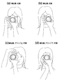
次に、図4を用いて、カメラの構え方とEVF9の観察の仕方について説明する。図4(a)は、カメラを横位置に構え、右眼でEVF9を観察している様子を示す。この状態では、撮影者の左眼はカメラ本体によって遮られずに、前方の被写体を見ることができる。図4(b)は、カメラを横位置に構え、左眼でEVF9を観察している様子を示す。この状態では、撮影者の右眼は前方の被写体を見ることができるが、カメラ本体の上部が邪魔して被写体を見難い。 Next, referring to FIG. 4, how to hold the camera and how to observe the EVF 9 will be described. FIG. 4A shows a state where the camera is held in a horizontal position and the EVF 9 is observed with the right eye. In this state, the left eye of the photographer can see the subject ahead without being blocked by the camera body. FIG. 4B shows a state in which the camera is held in the horizontal position and the EVF 9 is observed with the left eye. In this state, the photographer's right eye can see the subject in front, but the upper part of the camera body is obstructing and it is difficult to see the subject.
図4(c)は、カメラを縦位置に構え、グリップ部Gを上にし、右眼でEVF9を観察している様子を示す。この状態では、撮影者の左眼はカメラ本体によって遮られずに、前方の被写体を見ることができる。図4(d)は、カメラを縦位置に構え、グリップ部Gを下にし、右眼でEVF9を観察している様子を示す。この状態では、撮影者の左眼はカメラ本体によって遮られるので前方の被写体を見ることができない。 FIG. 4C shows a state in which the camera is held in the vertical position, the grip portion G is up, and the EVF 9 is observed with the right eye. In this state, the left eye of the photographer can see the subject ahead without being blocked by the camera body. FIG. 4D shows a state where the camera is held in the vertical position, the grip portion G is down, and the EVF 9 is observed with the right eye. In this state, the left eye of the photographer is blocked by the camera body, so that the subject in front cannot be seen.
このように、撮影者が右眼でEVF9を観察している場合には、左眼は前方の被写体を直接見ることができ、一方、左眼でEVF9を観察している場合には、右眼で前方の被写体を直接見ることができない。また、撮影者が右眼でEVF9を観察している場合であっても、カメラを縦位置に構え、グリップ部Gを下にした場合は、左眼は前方の被写体を直接見ることができない。 As described above, when the photographer observes the EVF 9 with the right eye, the left eye can directly see the subject in front, whereas when the EVF 9 is observed with the left eye, the right eye I can't see the subject in front. Even when the photographer is observing the EVF 9 with the right eye, if the camera is held in a vertical position and the grip portion G is down, the left eye cannot directly see the subject in front.
次に、図5を用いて、撮影者がEVF9を右眼で見ているか、それとも左眼で見ているかを判定する方法について説明する。 Next, a method for determining whether the photographer is viewing the EVF 9 with the right eye or the left eye will be described with reference to FIG.
図5(a)は、カメラを縦位置に構え、グリップ部Gを下にし、右眼で接眼レンズ11を介してEVF9を観察している様子を示している。この状態では、タッチパネル19aのエリアA(図5(a)で右下の領域)において、撮影者15の鼻が背面表示部19にタッチする。タッチパネル19aが、エリアA内におけるタッチ位置を検出し、制御部31に出力する。したがって、制御部31内のCPUは、姿勢検出部5が縦位置かつグリップ部Gが下側であることを検出した場合に(前述の図4(d)と同じ状態)、タッチパネル19aがエリアAでタッチ位置を検出した場合には、右眼でEVF9を観察していると判定する。
FIG. 5A shows a state in which the EVF 9 is observed through the
一方、カメラを縦位置に構え、グリップ部Gを下にし、左眼で接眼レンズ11を介してEVF9を観察している場合には、タッチパネル19aのエリアAにおいて、撮影者15の鼻が背面表示部19にタッチすることはない。したがって、制御部31内のCPUは、姿勢検出部5が縦位置を検出し、グリップ部Gが下にあると判定した場合に、タッチパネル19aがエリアAでタッチ位置を検出しない場合には、左眼でEVF9を観察していると判定する。
On the other hand, when the camera is held in the vertical position, the grip part G is down, and the EVF 9 is observed with the left eye through the
図5(b)は、カメラを縦位置に構え、グリップ部Gを上にし、左眼で接眼レンズ11を介してEVF9を観察している様子を示している。この状態では、タッチパネル19aのエリアB(図5(b)で左下の領域)において、撮影者15の鼻が背面表示部19にタッチする。タッチパネル19aが、エリアB内におけるタッチ位置を検出し、制御部31に出力する。したがって、制御部31内のCPUは、姿勢検出部5が縦位置かつグリップ部Gが上にあることを検出した場合に、タッチパネル19aがエリアBでタッチ位置を検出した場合には、左眼でEVF9を観察していると判定する。
FIG. 5B shows a state where the EVF 9 is observed through the
一方、カメラを縦位置に構え、グリップ部Gを上にし、右眼で接眼レンズ11を介してEVF9を観察している場合には(前述の図4(c)と同じ状態)、タッチパネル19aのエリアBにおいて、撮影者15の鼻が背面表示部19にタッチすることない。したがって、制御部31内のCPUは、姿勢検出部5が縦位置を検出し、グリップ部Gが上にあると判定した場合に、タッチパネル19aがエリアBでタッチ位置を検出しない場合には、右眼でEVF9を観察していると判定する。
On the other hand, when the camera is held in the vertical position, the grip part G is up, and the EVF 9 is observed with the right eye via the eyepiece 11 (the same state as in FIG. 4C), the
図5(c)は、カメラを横位置に構え、右眼で接眼レンズ11を介してEVF9を観察している様子を示している(前述の図4(a)と同じ状態)。この状態では、タッチパネル19aのエリアC(図5(c)で左側の領域)において、撮影者15の鼻が背面表示部19にタッチする。タッチパネル19aが、エリアC内におけるタッチ位置を検出し、制御部31に出力する。したがって、制御部31内のCPUは、姿勢検出部5が横位置を検出し、タッチパネル19aがエリアCでタッチ位置を検出した場合には、右眼でEVF9を観察していると判定する。
FIG. 5C shows a state where the camera is held in a horizontal position and the EVF 9 is observed with the right eye through the eyepiece 11 (the same state as in FIG. 4A described above). In this state, the nose of the
図5(d)は、カメラを横位置に構え、左眼で接眼レンズ11を介してEVF9を観察している様子を示し、前述の図4(b)と同じ状態である。この状態では、タッチパネル19aのエリアD(図5(d)で右側の領域)において、撮影者15の鼻が背面表示部19にタッチする。タッチパネル19aが、エリアD内におけるタッチ位置を検出し、制御部31に出力する。したがって、制御部31内のCPUは、姿勢検出部5が横位置を検出し、タッチパネル19aがエリアDでタッチ位置を検出した場合には、左眼でEVF9を観察していると判定する。
FIG. 5D shows a state in which the camera is placed in the horizontal position and the EVF 9 is observed with the left eye through the
このように、本実施形態においては、姿勢検出部5によるカメラの姿勢検出の結果と、タッチパネル19aのタッチ位置の検出結果に基づいて、撮影者が右眼でEVF9を観察しているか、左眼でEVF9を観察しているかを判定することができる。また、カメラの姿勢、すなわち、縦位置か横位置か、縦位置の場合にグリップが上か下かに応じて、タッチ位置を検出するエリアを制限している(例えば、図7のS45、S53、S57参照)。
Thus, in the present embodiment, based on the result of camera posture detection by the
次に、図6および図7に示すフローチャートを用いて、本実施形態における動作について、説明する。これらのフローは、制御部31内のCPUが、ROM25に記憶されているプログラムコードに従って、カメラ内の各部を制御することによって実行する。
Next, the operation in the present embodiment will be described using the flowcharts shown in FIGS. These flows are executed by the CPU in the
操作部27の電源釦がオンになると、動作を開始し、まず、初期化を行う(S1)。ここでは、各種フラグ等がリセットされ、また各種メカ機構がリセットされる。
When the power button of the
初期化を行うと、次に、撮像を開始する(S3)。ここでは、制御部31からの制御信号に従って撮像部3が所定のフレームレートで画像データを取得し、制御部31に出力する。制御部31内の画像処理部がライブビュー表示用に画像処理を施し、EVF制御部7に出力する。これによって、EVF9にライブビュー画像が表示される。以後、フレームレートに対応する時間が経過する毎に、ライブビュー画像が更新される。
Once initialization is performed, next, imaging is started (S3). Here, the
撮像を行うと、次に、接眼か否かを判定する(S5)。ここでは、アイセンサ17の検出出力に基づいて、撮影者の眼が、接眼レンズ11に接近しているか否かを判定する。すなわち、このステップでは、撮影者がファインダを覗いているか否かを検出する。
Once imaging has been performed, it is next determined whether or not the eyepiece is present (S5). Here, based on the detection output of the
ステップS5における判定の結果、接眼であった場合には、目的別・EVF表示を行う(S7)。ここでは、背面表示部19の表示をオフとし、EVF9でライブビュー表示を行う。この場合、カメラの構え方や、撮影者が右眼で見ているか左眼で見ているかを判定し、その結果に応じて、EVF9における表示の切り替えや、接眼レンズ11の視度調節を行う。この目的別・EVF表示の詳しい動作については、図7を用いて後述する。
If the result of determination in step S5 is eyepiece, purpose-specific / EVF display is performed (S7). Here, the display of the
一方、ステップS5における判定の結果、接眼でなかった場合には、背面表示を行う(S11)。ここでは、EVF9をオフとし、背面表示部19における表示をオンとする。撮影者は、背面表示部19にライブビュー表示されるので、このライブビュー画像を見て、構図やシャッタタイミングを決定する。
On the other hand, if the result of determination in step S5 is that there is no eyepiece, a rear display is performed (S11). Here, the EVF 9 is turned off and the display on the
ステップS7において目的別・EVF表示を行うと、またはステップS11において背面表示を行うと、次に、1R(SW)がオンか否かを判定する(S13)。ここでは、撮影者が操作部27のレリーズ釦を半押した場合に1Rがオンと判定され、半押しされていない場合には1Rがオフと判定すされる。この判定の結果、1Rがオフの場合には、ステップS3に戻り、前述の処理を繰り返す。
When the purpose-specific / EVF display is performed in step S7 or the rear display is performed in step S11, it is next determined whether 1R (SW) is on (S13). Here, when the photographer half-presses the release button of the
ステップS13における判定の結果、1Rがオンの場合には、次に、撮像を行う(S15)。ここでは、ステップS3と同様に、撮像部3から画像データを取得し、画像処理を施した後に、EVF9にライブビュー表示を行う。
If the result of determination in step S <b> 13 is that 1R is on, then imaging is performed (S <b> 15). Here, as in step S3, image data is acquired from the
撮像を行うと、次に、AE・AFを行う(S17)。AE(Auto Exposure)は、撮像部3からの画像データに基づいて、適正露光となる絞り値、シャッタ速度値、ISO感度値等の露出制御値を算出する。またAF(Auto Focus)は、撮影レンズ1を合焦となる位置に調節する。自動焦点検出方法としては、例えば、撮像部3からの画像データに基づいて焦点検出用の評価値を算出し、この評価値がピークとなる位置に撮影レンズ1を調節する。
Once imaging has been performed, AE / AF is then performed (S17). AE (Auto Exposure) calculates exposure control values such as an aperture value, a shutter speed value, and an ISO sensitivity value for appropriate exposure based on image data from the
AEとAFを行うと、次に、ステップS5と同様に接眼か否かを判定する(S19)。この判定の結果、接眼の場合には、ステップS7と同様に、目的別・EVF表示を行う(S21)。一方、接眼していなかった場合には、ステップS11と同様に、背面表示を行う(S23)。このように、レリーズ釦が半押しされた場合にも、EVF9を覗いているか否かに応じて、EVF9または背面表示部19のいずれかでライブビュー表示を行う。また、EVF9を覗いている場合には、右眼か左眼に応じて、ファインダの機能制御を行っている。
Once AE and AF have been performed, it is next determined whether or not the eyepiece is the same as in step S5 (S19). As a result of the determination, in the case of an eyepiece, the purpose-specific / EVF display is performed as in step S7 (S21). On the other hand, when the eye is not in contact, the rear display is performed as in step S11 (S23). In this way, even when the release button is pressed halfway, live view display is performed on either the EVF 9 or the
ステップS21において目的別・EVF表示を行うと、またはステップS23において背面表示を行うと、次に、2R(SW)がオンか否かを判定する(S25)。ここでは、撮影者が操作部27のレリーズ釦を全押した場合に2Rがオンと判定され、全押しされていない場合には2Rがオフと判定される。この判定の結果、2Rがオフの場合には、ステップS13に戻り、前述の処理を繰り返す。
If the purpose / EVF display is performed in step S21 or the rear display is performed in step S23, it is next determined whether or not 2R (SW) is on (S25). Here, 2R is determined to be on when the photographer fully presses the release button of the
ステップS25における判定の結果、2Rがオンの場合には、撮影を行う(S27)。ここでは、ステップS17において算出された適正露光となる露出制御値で、絞りやシャッタ等を制御し、シャッタ速度で決まる露出時間の経過後に撮像部3の撮像素子から画像データを読み出す。
If the result of determination in step S25 is that 2R is on, shooting is carried out (S27). Here, the aperture, shutter, and the like are controlled with the exposure control value that is the appropriate exposure calculated in step S17, and image data is read from the image sensor of the
撮影を行うと、次に、記録する(S29)。ここでは、読み出された画像データに対して、記録用の画像処理を施し、記録部21に画像データを記録する。
Once shooting has been carried out, it is next recorded (S29). Here, image processing for recording is performed on the read image data, and the image data is recorded in the
記録を行うと、次に、電源がオフか否かを判定する(S31)。ここでは、操作部27の電源釦がオフか否かを判定する。この判定の結果、電源オフでない場合には、ステップS3に戻り、前述の動作を繰り返す。一方、判定の結果、電源オフの場合には、カメラ制御のフローを終了する。
Once recording has been carried out, it is next determined whether or not the power is off (S31). Here, it is determined whether or not the power button of the
次に、図7に示すフローチャートを用いて、ステップS7およびS21における目的別・EVF表示の動作について説明する。 Next, the operation for each purpose / EVF display in steps S7 and S21 will be described with reference to the flowchart shown in FIG.
目的別・EVF表示のフローに入ると、まず、姿勢検出を行う(S41)。ここでは、姿勢検出部5がカメラの姿勢を検出し、その結果をCPUに出力する。
If the flow for each purpose / EVF display is entered, first, posture detection is performed (S41). Here, the
姿勢検出を行うと、次に縦位置か否かの判定を行う(S43)。ここでは、ステップS41における検出結果に基づいて、カメラが縦位置で構えられているか横位置で構えられているかを判定する。 Once the posture is detected, it is next determined whether or not the position is vertical (S43). Here, based on the detection result in step S41, it is determined whether the camera is held in the vertical position or the horizontal position.
ステップS43における判定の結果、縦位置でなかった場合には、すなわち、横位置の場合には、検出エリアC、Dについて検出を行う(S45)。ここでは、図5(c)(d)に示すエリアCとエリアDについて、タッチパネル19aがタッチ状態を検出する。
If the result of determination in step S43 is that the position is not vertical, that is, if it is horizontal, detection is performed for detection areas C and D (S45). Here, for the areas C and D shown in FIGS. 5C and 5D, the
次に、エリアCがタッチされたか否かを判定する(S47)。ここでは、ステップS45における検出結果に基づいて、エリアCがタッチされた否かを判定する。この判定の結果、エリアCがタッチされていなかった場合には、エリアDがタッチされたか否かを判定する(S49)。ここでは、ステップS45における検出結果に基づいて、エリアDがタッチされたか否かを判定する。 Next, it is determined whether or not the area C is touched (S47). Here, based on the detection result in step S45, it is determined whether or not the area C is touched. If the result of this determination is that area C has not been touched, it is determined whether or not area D has been touched (S49). Here, based on the detection result in step S45, it is determined whether or not the area D has been touched.
ステップS43における判定の結果、縦位置であった場合には、次に、グリップが下にあるか否かを判定する(S51)。ここでは、ステップS41における検出結果に基づいて、グリップが下にあるか否かを判定する。 If the result of determination in step S43 is that it is in the vertical position, it is next determined whether or not the grip is down (S51). Here, based on the detection result in step S41, it is determined whether or not the grip is below.
ステップS51における判定の結果、グリップが下にある場合には、次に、検出エリアAのタッチ状態を検出する(S53)。ここでは、図5(a)に示すエリアAについて、タッチパネル19aがタッチ状態を検出する。
If the result of determination in step S51 is that the grip is below, next, the touch state of the detection area A is detected (S53). Here, for the area A shown in FIG. 5A, the
続いて、エリアAがタッチされたか否かを判定する(S55)。ここでは、ステップS53における検出結果に基づいて判定する。 Subsequently, it is determined whether or not the area A is touched (S55). Here, it determines based on the detection result in step S53.
ステップS51における判定の結果、グリップが下になかった場合には、次に、検出エリアBにおいてタッチ状態を検出する(S57)。ここでは、図5(b)に示すエリアBについて、タッチパネル19aがタッチ状態を検出する。
If the result of determination in step S51 is that the grip is not below, next, a touch state is detected in detection area B (S57). Here, for the area B shown in FIG. 5B, the
続いて、エリアBがタッチされたか否かを判定する(S59)。ここでは、ステップS57における検出結果に基づいて判定する。 Subsequently, it is determined whether or not the area B is touched (S59). Here, the determination is made based on the detection result in step S57.
ステップS41〜S59において、カメラが縦位置であるか横位置であるか、また縦位置の場合にはグリップが上であるか下であるかについて判定される。そして、それぞれの状態においてタッチパネル19aにおける所定のエリアにおけるタッチ位置を検出する(S45、S53、S57)。この検出結果に基づいて、次に、右眼か左眼のいずれでEVF9を観察しているかを、ステップS61、S67において判別する。
In steps S41 to S59, it is determined whether the camera is in the vertical position or the horizontal position, and if the camera is in the vertical position, the grip is up or down. And the touch position in the predetermined area in the
ステップS47においてエリアCでタッチ状態であると判定された場合、またはステップS49においてエリアDでタッチ状態でないと判定された場合、またはステップS55において、エリアAでタッチ状態であると判定された場合、またはステップS59において、エリアBでタッチ状態でないと判定された場合には、右眼と判別する(S61)。 If it is determined in step S47 that the touch is in area C, if it is determined in step S49 that it is not in the touch state in area D, or if it is determined in step S55 that the touch is in area A, Alternatively, when it is determined in step S59 that the touch state is not in area B, the right eye is determined (S61).
すなわち、ステップS47においてエリアCでタッチ状態であると判定された場合、またはステップS49においてエリアDでタッチ状態でないと判定された場合は、カメラが横位置にあり、エリアCでタッチ状態であるか、エリアDはタッチ状態でないことから、図5(c)に示すように、右眼でEVF9を覗いている状態である。 That is, if it is determined in step S47 that the area C is in the touch state, or if it is determined in step S49 that the area D is not in the touch state, is the camera in the horizontal position and whether the area C is in the touch state? Since the area D is not in the touched state, as shown in FIG. 5C, the right eye is looking into the EVF 9.
また、ステップS55において、エリアAでタッチ状態であると判定された場合は、カメラが縦位置で、グリップ部Gが下にあり、エリアAがタッチ状態であることから、図5(a)に示すように、右眼でEVF9を覗いている状態である。 If it is determined in step S55 that the area A is in the touched state, the camera is in the vertical position, the grip portion G is below, and the area A is in the touched state. As shown, the right eye is looking into the EVF 9.
また、ステップS59において、エリアBでタッチ状態でないと判定された場合は、カメラが縦位置でグリップ部Gが上にあり、エリアBがタッチ状態でないかことから、右眼でEVF9を覗いている状態である(図5(b)参照)。 If it is determined in step S59 that the area B is not in the touched state, the camera is in the vertical position and the grip portion G is at the top, and the area B is not in the touched state. It is a state (refer FIG.5 (b)).
一方、ステップS49においてエリアDでタッチ状態であると判定された場合、またはステップS55においてエリアAでタッチ状態でないと判定された場合、またはステップS59においてエリアBでタッチ状態であると判定された場合には、左眼と判別する(S67)。 On the other hand, if it is determined in step S49 that the area D is in the touched state, if it is determined in step S55 that the area A is not in the touched state, or if it is determined in step S59 that the area B is in the touched state. Is determined to be the left eye (S67).
すなわち、ステップS49においてエリアDでタッチ状態であると判定された場合は、カメラは横位置にあり、エリアDでタッチ状態であることから、図5(d)に示すように、左眼でEVF9を覗いている状態である。 That is, if it is determined in step S49 that the touch state is in the area D, the camera is in the horizontal position and the touch state is in the area D. Therefore, as shown in FIG. Is in a state of peeking.
また、ステップS55においてエリアAでタッチ状態でないと判定された場合は、カメラは縦位置にあり、グリップ部Gは下にあり、エリアAはタッチ状態でないことから、左眼でEVF9を覗いている状態である(図5(a)参照)。 If it is determined in step S55 that the area A is not in the touch state, the camera is in the vertical position, the grip portion G is below, and the area A is not in the touch state. It is in a state (see FIG. 5A).
また、ステップS59においてエリアBでタッチ状態であると判定された場合は、カメラは縦位置にあり、グリップ部Gは上にあり、エリアBはタッチ状態であることから、図5(b)に示すように、左眼でEVF9を覗いている状態である。 If it is determined in step S59 that the area B is in the touched state, the camera is in the vertical position, the grip portion G is on the upper side, and the area B is in the touched state. As shown, the left eye is looking into the EVF 9.
ステップS61およびS67において、EVF9を覗いている眼が右眼か左眼かを判別すると、ステップS63、S65、S69、S71において、それぞれの眼に応じたEVF9の機能制御を行う。 If it is determined in steps S61 and S67 whether the eye looking into the EVF 9 is the right eye or the left eye, in steps S63, S65, S69, and S71, function control of the EVF 9 corresponding to each eye is performed.
ステップS61において、右眼と判別した場合には、右眼用視度調節を行う(S63)。ここでは、予め測定された撮影者の右眼の視度データを、ROM25から読み出し、この読み出した視度データに基づいて視度調整部13が接眼レンズ11の視度調整を行う。
If the right eye is determined in step S61, diopter adjustment for the right eye is performed (S63). Here, diopter data of the photographer's right eye measured in advance is read from the
一方、ステップS67において、左眼と判別した場合には、左眼用視度調節を行う(S69)。ここでは、予め測定された撮影者の左眼の視度データを、ROM25から読み出し、この読み出した視度データに基づいて視度調整部13が接眼レンズ11の視度調整を行う。
On the other hand, if the left eye is determined in step S67, diopter adjustment for the left eye is performed (S69). Here, the diopter data of the left eye of the photographer measured in advance is read from the
このように、ステップS63またはS67において、撮影者が実際に覗いている眼が右眼であるか、左眼であるかを判別し、この判別結果に応じて視度調整しているので、撮影者はEVF9を覗いた際にピントのあった画像を観察することができる。 In this way, in step S63 or S67, it is determined whether the eye that the photographer is actually looking into is the right eye or the left eye, and the diopter is adjusted according to the determination result. A person can observe a focused image when looking into the EVF 9.
ステップS63において、右眼用視度調節を行うと、次に、ナチュラル表示データの作成と高フレームレートの設定を行う(S65)。また、ステップS69において、左眼用視度調節を行うと、次に、没入感のある表示データの作成を行う(S71)。 If the diopter adjustment for the right eye is performed in step S63, next, natural display data is created and a high frame rate is set (S65). If the diopter adjustment for the left eye is performed in step S69, display data with immersive feeling is created (S71).
両ステップにおける処理について、図8を用いて説明する。ステップS65において、図8の「右眼」と記載されている列の処理を実行し、ステップS71において、図8の「左眼」と記載されている列の処理を実行する。 Processing in both steps will be described with reference to FIG. In step S65, the process of the column described as “right eye” in FIG. 8 is executed. In step S71, the process of the column described as “left eye” in FIG. 8 is executed.
まず、フレームレートについては、図8の第1段の記載に沿って設定を行う。すなわち、撮影者が右眼でEVF9を観察している場合には(S65)、高速のフレームレートに設定する。一方、左眼でEVF9を観察している場合には(S71)、通常のフレームレートに設定する。撮影者が右眼でEVF9を観察している場合には、左眼で直接被写体を観察できることから、EVF9で表示遅れが生ずることを防止するために、高速のフレームレートを設定する。一方、撮影者が左眼でEVF9を観察している場合には、通常、右眼で被写体を観察していないので、通常のフレームレートを設定する。なお、フレームレートは、制御部31から撮像部3内の撮像素子駆動回路に制御信号を送信し、設定する。
First, the frame rate is set according to the description in the first row of FIG. That is, when the photographer is observing the EVF 9 with the right eye (S65), a high frame rate is set. On the other hand, when the EVF 9 is observed with the left eye (S71), the normal frame rate is set. When the photographer is observing the EVF 9 with the right eye, the subject can be directly observed with the left eye. Therefore, in order to prevent a display delay from occurring in the EVF 9, a high frame rate is set. On the other hand, when the photographer is observing the EVF 9 with the left eye, since the subject is not normally observed with the right eye, a normal frame rate is set. The frame rate is set by transmitting a control signal from the
アートLV(ライブビュー)モードがメニュー画面等において設定されている場合には、図8の第2段の記載に沿って処理を行う。すなわち、撮影者が左眼でEVF9を観察している場合には(S71)、設定されたアートLVモードに従って画像データに画像処理を施して表示用の画像データを生成する。一方、右眼でEVF9を観察している場合には(S65)、アートLVモードが設定されていても、EVF9にはアートLVモードによる表示を行わず、通常のライブビュー画像の画像データを生成する。撮影者が右眼でEVF9を観察している場合には、左眼で直接被写体を観察することができ、このとき左右の眼で見る像が大きく異なると違和感が生じてしまうのを防止するためである。 When the art LV (live view) mode is set on the menu screen or the like, the processing is performed according to the description in the second row of FIG. That is, when the photographer is observing the EVF 9 with the left eye (S71), the image data is subjected to image processing according to the set art LV mode to generate display image data. On the other hand, when the EVF 9 is observed with the right eye (S65), even if the art LV mode is set, the EVF 9 does not display the art LV mode, and generates image data of a normal live view image. To do. When the photographer is observing the EVF 9 with the right eye, the subject can be directly observed with the left eye. In this case, in order to prevent a sense of incongruity from occurring when the images seen by the left and right eyes are greatly different. It is.
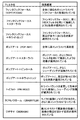
なお、アートLVモードとしては、例えば、図9に示すように、「ファンタジックフォーカス」、「ファンタジックフォーカス+スターライト」、「ファンタジックフォーカス+ホワイトエッジ」、「ポップアート」、「ポップアート+スターライト」、「ポップアート+ピンホール」、「ポップアート+ホワイトエッジ」、「トイフォト」、「ラフモノクローム」、「ジオラマ」等、種々の画像処理がある。 As the art LV mode, for example, as shown in FIG. 9, "Fantastic focus", "Fantastic focus + Starlight", "Fantastic focus + White edge", "Pop art", "Pop art + Starlight" , “Pop art + pinhole”, “pop art + white edge”, “toy photo”, “rough monochrome”, “diorama”, and the like.
OVF(Optical View Finder)シミュレーションがメニュー画面等において設定されている場合には、図8の第3段の記載に沿って処理を行う。OVFシミュレーションモードは、EVF9において、光学式ファインダにおける被写体像と同等の画像を表示させるモードである。撮影者が右眼でEVF9を観察している場合には(S65)、設定されたOVFシミュレーションモードに従って画像データに画像処理を施し、表示用の画像データを生成する。一方、左眼でEVF9を観察している場合には(S71)、OVFシミュレーションモードが設定されていても、EVF9にはOVFシミュレーションモードによる画像データを生成せずに、通常のライブビュー画像の画像データを生成する。 When OVF (Optical View Finder) simulation is set on the menu screen or the like, processing is performed according to the description in the third row of FIG. The OVF simulation mode is a mode for displaying an image equivalent to the subject image in the optical viewfinder in the EVF 9. When the photographer is observing the EVF 9 with the right eye (S65), the image data is subjected to image processing according to the set OVF simulation mode to generate image data for display. On the other hand, when the EVF 9 is observed with the left eye (S71), even if the OVF simulation mode is set, the EVF 9 does not generate image data in the OVF simulation mode, and the image of the normal live view image is displayed. Generate data.
LVブーストがメニュー画面等において設定されている場合には、図8の第4段の記載に沿って処理を行う。LVブーストモードは、画像の輝度を増幅し、暗闇であっても昼間のように明るく画像を表示させるモードである。撮影者が左眼でEVF9を観察している場合には(S71)、被写体像が明るくなるように画像データに画像処理を施し、表示用の画像データを生成する。一方、右眼でEVF9を観察している場合には(S65)、LVブーストモードが設定されていても、EVF9にはLVブーストモードによる画像データを生成せず、通常のライブビュー画像表示用の画像データを生成する。撮影者が右眼でEVF9を観察している場合には、左眼で直接被写体を観察しており、このとき左右の眼で見る像が大きく異なると違和感が生じてしまうのを防止するためである。 When LV boost is set on the menu screen or the like, processing is performed according to the description in the fourth row of FIG. The LV boost mode is a mode in which the brightness of the image is amplified and the image is displayed brightly as in the daytime even in the dark. When the photographer is observing the EVF 9 with the left eye (S71), image processing is performed on the image data so that the subject image becomes bright, and display image data is generated. On the other hand, when the EVF 9 is observed with the right eye (S65), even if the LV boost mode is set, the EVF 9 does not generate image data in the LV boost mode, and is used for normal live view image display. Generate image data. When the photographer observes the EVF 9 with the right eye, the subject is directly observed with the left eye. At this time, it is possible to prevent a sense of incongruity from occurring when the images seen by the left and right eyes are greatly different. is there.
ナチュラルビューがメニュー画面等において設定されている場合には、図8の第5段の記載に沿って処理を行う。ナチュラルビューモードは、画像が自然に見えるように画像処理を施すモードである。撮影者が右眼でEVF9を観察している場合には(S65)、ナチュラルビューモードによる画像処理を施し、表示用の画像データを生成する。一方、左眼でEVF9を観察している場合には(S71)、ナチュラルビューモードが設定されていても、EVF9にはナチュラルビューモードによる画像データを生成せず、アートLVモードが設定されていればそれを優先し、設定されていなければ通常のライブビュー画像表示用の画像データを生成する。なお、通常のライブビュー画像表示は、ナチュラルビューモードの画像表示よりも、コントラストや彩度が強調されており、より視認性を向上させるように設定されている。 When the natural view is set on the menu screen or the like, processing is performed according to the description in the fifth row of FIG. The natural view mode is a mode for performing image processing so that an image looks natural. When the photographer is observing the EVF 9 with the right eye (S65), image processing in the natural view mode is performed to generate display image data. On the other hand, when the EVF 9 is observed with the left eye (S71), even if the natural view mode is set, image data in the natural view mode is not generated in the EVF 9, and the art LV mode is set. If it is not set, image data for normal live view image display is generated. Note that the normal live view image display is set so that the contrast and saturation are emphasized and the visibility is improved more than the image display in the natural view mode.
なお、本実施形態においては、撮影者がEVF9を右眼で観察しているか、左眼で観察しているかによって、図8に示すようなファインダの機能制御を行っている。しかし、これに限らず、一部の機能制御を省略してもよく、また他の機能制御を追加してもよい。 In the present embodiment, the function control of the finder as shown in FIG. 8 is performed depending on whether the photographer is observing the EVF 9 with the right eye or the left eye. However, the present invention is not limited to this, part of the function control may be omitted, and other function control may be added.
ステップS65またはS71における処理を実行すると、EVF表示を行う(S73)。ここでは、ステップS65またはステップS71において生成された画像データを用いて、EVF9に表示を行う。EVF表示を行うと、元のフローに戻る。 When the processing in step S65 or S71 is executed, EVF display is performed (S73). Here, display is performed on the EVF 9 using the image data generated in step S65 or step S71. When EVF display is performed, the original flow is restored.
このように、本実施形態においては、ファインダを覗いていると検出されると(図6のS5、S19)、タッチパネルで検出される位置に応じて(図7のS47、S49、S55、S59)、ファインダの機能を制御している(図7のS63、S65、S69、S71)。 As described above, in this embodiment, when it is detected that the user is looking through the viewfinder (S5 and S19 in FIG. 6), depending on the position detected on the touch panel (S47, S49, S55, and S59 in FIG. 7). The function of the viewfinder is controlled (S63, S65, S69, S71 in FIG. 7).
以上説明したように、本発明の一実施形態においては、ファインダを覗いているか否かを検出する接眼検出部(例えば、アイセンサ17)と、タッチパネルの検出領域への物体のタッチ位置、またはタッチパネルに最も接近する物体の位置を検出する位置検出部(例えば、タッチパネル19a)と、接眼検出部によりファインダを覗いていると検出される場合に、位置検出部により検出される位置に応じて、ファインダの機能を制御する制御部(例えば、制御部31)を設けている。このため、撮影者がいずれの眼でファインダを覗いているかに応じて、ファインダの機能を制御することができる。
As described above, in one embodiment of the present invention, an eyepiece detection unit (for example, the eye sensor 17) that detects whether or not the user is looking through the viewfinder, and the touch position of an object on the detection area of the touch panel, or the touch panel When it is detected that the position detection unit (for example, the
なお、本発明の一実施形態においては、ファインダとして電子ビューファインダ(EVF9)を用いた例について説明した。しかし、これに限らず、ファインダとして光学式を用いてもよい。この場合には、図7のS65、S71に示したようなアートLVモードやOVFシミュレーションによる表示はできないが、ファインダの視度調節を行うことができる。 In the embodiment of the present invention, the example using the electronic viewfinder (EVF9) as the finder has been described. However, the present invention is not limited to this, and an optical system may be used as a finder. In this case, display by the art LV mode or the OVF simulation as shown in S65 and S71 of FIG. 7 cannot be performed, but diopter adjustment of the finder can be performed.
また、本実施形態においては、撮影のための機器として、デジタルカメラを用いて説明したが、カメラとしては、デジタル一眼レフカメラでもコンパクトデジタルカメラでもよく、ビデオカメラ、ムービーカメラのような動画用のカメラでもよく、さらに、携帯電話、スマートフォン、携帯情報端末(PDA:Personal Digital Assist)、パーソナルコンピュータ(PC)、タブレット型コンピュータ、ゲーム機器等に内蔵されるカメラでも構わない。いずれにしても、ファインダとタッチパネルを有する撮影のための機器であれば、本発明を適用することができる。 In the present embodiment, the digital camera is used as the photographing device. However, the camera may be a digital single-lens reflex camera or a compact digital camera, and may be used for moving images such as video cameras and movie cameras. It may be a camera, and may be a camera built in a mobile phone, a smart phone, a personal digital assistant (PDA), a personal computer (PC), a tablet computer, a game machine, or the like. In any case, the present invention can be applied to any device for photographing having a finder and a touch panel.
また、本明細書において説明した技術のうち、主にフローチャートで説明した制御に関しては、プログラムで設定可能であることが多く、記録媒体や記録部に収められる場合もある。この記録媒体、記録部への記録の仕方は、製品出荷時に記録してもよく、配布された記録媒体を利用してもよく、インターネットを介してダウンロードしたものでもよい。 Of the techniques described in this specification, the control mainly described in the flowchart is often settable by a program and may be stored in a recording medium or a recording unit. The recording method for the recording medium and the recording unit may be recorded at the time of product shipment, may be a distributed recording medium, or may be downloaded via the Internet.
また、特許請求の範囲、明細書、および図面中の動作フローに関して、便宜上「まず」、「次に」等の順番を表現する言葉を用いて説明したとしても、特に説明していない箇所では、この順で実施することが必須であることを意味するものではない。 In addition, regarding the operation flow in the claims, the specification, and the drawings, even if it is described using words expressing the order such as “first”, “next”, etc. It does not mean that it is essential to implement in this order.
本発明は、上記実施形態にそのまま限定されるものではなく、実施段階ではその要旨を逸脱しない範囲で構成要素を変形して具体化できる。また、上記実施形態に開示されている複数の構成要素の適宜な組み合わせにより、種々の発明を形成できる。例えば、実施形態に示される全構成要素の幾つかの構成要素を削除してもよい。さらに、異なる実施形態にわたる構成要素を適宜組み合わせてもよい。 The present invention is not limited to the above-described embodiments as they are, and can be embodied by modifying the constituent elements without departing from the scope of the invention in the implementation stage. In addition, various inventions can be formed by appropriately combining a plurality of components disclosed in the embodiment. For example, you may delete some components of all the components shown by embodiment. Furthermore, constituent elements over different embodiments may be appropriately combined.
1・・・撮影レンズ、3・・・撮像部、5・・・姿勢検出部、7・・・EVF制御部、9・・・EVF、11・・・接眼レンズ、13・・・視度調整部、15・・・撮影者、17・・・アイセンサ、19・・・背面表示部、19a・・・タッチパネル、21・・・記録部、23・・・RAM、25・・・ROM、27・・・操作部、31・・・制御部、100・・・カメラ本体、200・・・レンズ鏡筒、G・・・グリップ部
DESCRIPTION OF
Claims (6)
上記ファインダを覗いているか否かを検出する接眼検出部と、
上記タッチパネルの検出領域への物体のタッチ位置、または上記タッチパネルに最も接近する物体の位置を検出する位置検出部と、
上記接眼検出部により上記ファインダを覗いていると検出される場合に、上記位置検出部により検出される位置に応じて、上記ファインダの機能を制御する制御部と、
を有することを特徴とする撮像装置。 In an imaging device having a viewfinder and a touch panel,
An eyepiece detecting unit for detecting whether or not the user is looking through the viewfinder;
A position detection unit that detects a touch position of an object on a detection area of the touch panel or a position of an object closest to the touch panel;
A control unit that controls the function of the finder according to the position detected by the position detection unit when it is detected that the eyepiece detection unit is looking into the finder;
An imaging device comprising:
上記制御部は、上記姿勢検出部により検出される姿勢に応じて、上記タッチパネルの検出領域を制限する、
ことを特徴とする請求項1に記載の撮像装置。 An attitude detection unit for detecting the attitude of the imaging device;
The control unit limits a detection area of the touch panel according to the posture detected by the posture detection unit.
The imaging apparatus according to claim 1.
上記制御部は、上記位置検出部により検出される位置に応じて、右目で覗いているか左目で覗いているかを判別し、判別された目に応じて、上記ファインダの視度を調節する、
ことを特徴とする請求項1又は2に記載の撮像装置。 The viewfinder can adjust the diopter,
The control unit determines whether the right eye or the left eye is looking according to the position detected by the position detection unit, and adjusts the diopter of the finder according to the determined eye.
The imaging apparatus according to claim 1 or 2, wherein
上記制御部は、上記位置検出部により検出される位置に応じて、右目で覗いているか左目で覗いているかを判別し、判別された目に応じて、上記表示部の表示のフレームレートを設定する、
ことを特徴とする請求項1又は2に記載の撮像装置。 The finder has a display unit that displays based on captured image data,
The control unit determines whether the right eye or the left eye is looking according to the position detected by the position detection unit, and sets the display frame rate of the display unit according to the determined eye To
The imaging apparatus according to claim 1 or 2, wherein
上記制御部は、上記位置検出部により検出される位置に応じて、右目で覗いているか左目で覗いているかを判別し、判別された目に応じて、上記表示部に表示する画像に特殊効果を付加する度合いを設定する、
ことを特徴とする請求項1又は2に記載の撮像装置。 The finder has a display unit that displays based on captured image data,
The control unit determines whether the right eye or the left eye is looking according to the position detected by the position detection unit, and the special effect is applied to the image displayed on the display unit according to the determined eye. Set the degree to add
The imaging apparatus according to claim 1 or 2, wherein
上記ファインダを覗いているか否かを検出し、
上記タッチパネルの検出領域への物体のタッチ位置、または上記タッチパネルに最も接近する物体の位置を検出し、
上記ファインダを覗いていると検出される場合に、上記タッチパネルで検出される位置に応じて、上記ファインダの機能を制御する、
ことを特徴とする撮像方法。
In an imaging method in an imaging apparatus having a finder and a touch panel,
Detect whether you are looking through the finder,
Detect the touch position of the object to the detection area of the touch panel or the position of the object closest to the touch panel,
When it is detected that the user is looking through the finder, the function of the finder is controlled according to the position detected by the touch panel.
An imaging method characterized by the above.
Priority Applications (1)
| Application Number | Priority Date | Filing Date | Title |
|---|---|---|---|
| JP2015105541A JP2016220133A (en) | 2015-05-25 | 2015-05-25 | Imaging device and imaging method |
Applications Claiming Priority (1)
| Application Number | Priority Date | Filing Date | Title |
|---|---|---|---|
| JP2015105541A JP2016220133A (en) | 2015-05-25 | 2015-05-25 | Imaging device and imaging method |
Publications (1)
| Publication Number | Publication Date |
|---|---|
| JP2016220133A true JP2016220133A (en) | 2016-12-22 |
Family
ID=57578691
Family Applications (1)
| Application Number | Title | Priority Date | Filing Date |
|---|---|---|---|
| JP2015105541A Pending JP2016220133A (en) | 2015-05-25 | 2015-05-25 | Imaging device and imaging method |
Country Status (1)
| Country | Link |
|---|---|
| JP (1) | JP2016220133A (en) |
Cited By (1)
| Publication number | Priority date | Publication date | Assignee | Title |
|---|---|---|---|---|
| JP2019184771A (en) * | 2018-04-06 | 2019-10-24 | キヤノン株式会社 | Imaging apparatus and control method of the same |
-
2015
- 2015-05-25 JP JP2015105541A patent/JP2016220133A/en active Pending
Cited By (2)
| Publication number | Priority date | Publication date | Assignee | Title |
|---|---|---|---|---|
| JP2019184771A (en) * | 2018-04-06 | 2019-10-24 | キヤノン株式会社 | Imaging apparatus and control method of the same |
| JP7071197B2 (en) | 2018-04-06 | 2022-05-18 | キヤノン株式会社 | Imaging device and its control method |
Similar Documents
| Publication | Publication Date | Title |
|---|---|---|
| US10623647B2 (en) | Image capturing apparatus and control method for changing a setting based on a touch operation on a display | |
| JP4884417B2 (en) | Portable electronic device and control method thereof | |
| US8605188B2 (en) | Camera having a rear-surface display section and an in-viewfinder display section | |
| US9172881B2 (en) | Camera and method of controlling operation of same | |
| JP5809891B2 (en) | Imaging device | |
| JP5959217B2 (en) | Imaging apparatus, image quality adjustment method, and image quality adjustment program | |
| JP6515924B2 (en) | Imaging device | |
| JP2005143112A (en) | Camera and method concerning the same | |
| JP2014068081A (en) | Imaging apparatus and control method of the same, program and storage medium | |
| JP6476064B2 (en) | Imaging apparatus and imaging control method | |
| JP2007086460A (en) | Camera | |
| CN107800956B (en) | Image pickup apparatus, control method, and storage medium | |
| KR101812656B1 (en) | Digital photographing apparatus and control method thereof | |
| JP2016220133A (en) | Imaging device and imaging method | |
| JP2008060811A (en) | Imaging apparatus | |
| JP5715269B2 (en) | Camera, camera control method, and program | |
| JP2010176460A (en) | Electronic device and camera | |
| CN112040095A (en) | Electronic device, control method of electronic device, and storage medium | |
| JP6320251B2 (en) | Imaging apparatus, imaging method, and program | |
| JP2015228537A (en) | Imaging apparatus | |
| JP2020134766A (en) | Imaging apparatus and method for controlling imaging apparatus | |
| JP2014236284A (en) | Imaging apparatus | |
| JP5053158B2 (en) | Display device, operation control method, and program | |
| JP6506440B2 (en) | Imaging device, imaging method, and program | |
| JP5963440B2 (en) | Imaging apparatus and control method thereof |