JP5963440B2 - Imaging apparatus and control method thereof - Google Patents
Imaging apparatus and control method thereof Download PDFInfo
- Publication number
- JP5963440B2 JP5963440B2 JP2011288270A JP2011288270A JP5963440B2 JP 5963440 B2 JP5963440 B2 JP 5963440B2 JP 2011288270 A JP2011288270 A JP 2011288270A JP 2011288270 A JP2011288270 A JP 2011288270A JP 5963440 B2 JP5963440 B2 JP 5963440B2
- Authority
- JP
- Japan
- Prior art keywords
- shooting
- scene
- detected
- shooting scene
- flash
- Prior art date
- Legal status (The legal status is an assumption and is not a legal conclusion. Google has not performed a legal analysis and makes no representation as to the accuracy of the status listed.)
- Expired - Fee Related
Links
Images


Landscapes
- Exposure Control For Cameras (AREA)
- Stroboscope Apparatuses (AREA)
- Studio Devices (AREA)
Description
本発明は、撮像装置において、撮影シーンに応じてストロボ発光及び連続撮影を自動で設定する技術に関する。 The present invention relates to a technique for automatically setting strobe light emission and continuous shooting according to a shooting scene in an imaging apparatus.
従来、撮影シーンに応じてストロボ発光モード及び連続撮影モードを自動で設定することができるデジタルカメラ等の撮像装置が知られている。この種の装置では、例えば、カメラが逆光シーンを検出した場合、被写体を適正な露出で撮影するために、ストロボ発光モードを「発光」に自動設定する。また、カメラが人物の笑顔があるシーンを検出した場合、最も好ましい表情となる瞬間を残すために、高速に連続撮影を行うよう自動設定する。また、カメラが子供の動きまわるシーンを検出した場合、動きのある様々なシーンを残すために、所定のコマ速で連続撮影を行うよう自動設定する。 2. Description of the Related Art Conventionally, an imaging device such as a digital camera that can automatically set a flash emission mode and a continuous shooting mode according to a shooting scene is known. In this type of apparatus, for example, when the camera detects a backlight scene, the flash emission mode is automatically set to “flash” in order to photograph the subject with an appropriate exposure. Also, when the camera detects a scene with a human smile, it automatically sets to perform continuous shooting at a high speed in order to leave the moment when the most desirable facial expression is obtained. In addition, when the camera detects a scene in which the child moves, in order to leave various scenes with movement, automatic setting is performed so that continuous shooting is performed at a predetermined frame speed.
ここで、カメラが逆光シーン且つ人物の笑顔を検出した場合、あるいは逆光シーン且つ子供の動きまわるシーンを検出した場合について考える。 Here, a case where the camera detects a backlight scene and a smiling face of a person, or a case where a camera detects a backlight scene and a scene in which a child moves around is considered.
これらの場合、カメラはストロボ発光モードを「発光」に自動設定し、且つ所定のコマ速での連続撮影を行うよう自動設定する。しかし、ストロボ発光時においては撮影ごとに充電完了を待つ必要があるため、所定のコマ速での連続撮影が実現できない場合がある。そのため、ユーザはいつ撮影が終了するのかわからず、カメラを被写体に向けたまま待つ必要があった。 In these cases, the camera automatically sets the flash emission mode to “flash” and automatically sets continuous shooting at a predetermined frame speed. However, since it is necessary to wait for the charging to be completed every time the flash is fired, continuous shooting at a predetermined frame speed may not be realized. Therefore, the user does not know when the shooting is finished, and has to wait with the camera facing the subject.
これに対して、例えば特許文献1は、ストロボ発光での連続撮影においては通常より弱い発光量で発光を行うようにし、コマ速が長くなるのを防いでいる。また、特許文献2では、ストロボ発光での連続撮影においてはストロボが最低充電電圧以下にならないようにコマ速を長く設定している。 On the other hand, for example, in Patent Document 1, light is emitted with a light emission amount that is weaker than usual in continuous shooting with strobe light emission to prevent the frame speed from becoming long. In Patent Document 2, in continuous shooting with strobe light emission, the frame speed is set to be long so that the strobe does not fall below the minimum charging voltage.
しかしながら、特許文献1のように通常より弱い発光量で発光を行うようにすると、各撮影画像が適正な露出にならない場合がある。また、特許文献2のようにコマ速を長く設定すると、シーンに応じた最適なタイミングでの撮影が行えない。例えば人物の笑顔を検出した場合は、被写体の瞬きや表情の一瞬の変化を捉えるために高速に連続撮影を行うことが求められるが、コマ速が長くなるとその要求を満たせなくなってしまう。従って、撮影シーンによっては、適切な露出及びタイミングでの撮像画像を得ることが困難となるという問題があった。 However, if the light emission is performed with a light emission amount that is weaker than usual as in Patent Document 1, each captured image may not be properly exposed. If the frame speed is set to be long as in Patent Document 2, it is not possible to perform shooting at an optimal timing according to the scene. For example, when a smiling face of a person is detected, it is required to perform continuous shooting at a high speed in order to capture a blink of a subject or a change in facial expression. However, when the frame speed increases, the request cannot be satisfied. Therefore, there is a problem that it becomes difficult to obtain a captured image with appropriate exposure and timing depending on the shooting scene.
本発明は上記従来技術の問題を解決するためになされたものであり、その目的は、適切な露出及びタイミングでの撮像画像を得ることができる撮像装置及びその制御方法を提供することにある。 The present invention has been made to solve the above-described problems of the prior art, and an object thereof is to provide an imaging apparatus capable of obtaining a captured image with appropriate exposure and timing and a control method thereof.
上記目的を達成するために本発明は、撮像手段と、前記撮像手段により得られる被写体画像から、ストロボ発光をさせて撮影を行うべき第1の撮影シーンまたは連続撮影を行うべき第2の撮影シーンをそれぞれ撮影シーンとして検出する検出手段と、前記検出手段により検出された撮影シーンに応じて、ストロボ発光またはストロボ非発光のいずれとするか、及び、連続撮影または一枚撮影のいずれとするかを制御モードとして設定して撮影を制御する制御手段とを有し、前記検出手段は、前記得られる被写体画像の露出値が第1の露出閾値を下回る場合は、前記第1の撮影シーンであることを検出し、前記制御手段は、前記検出手段により前記第1の撮影シーンが検出され且つ前記第2の撮影シーンが検出されない場合は前記制御モードをストロボ発光且つ一枚撮影に設定し、前記検出手段により前記第1の撮影シーンが検出されず且つ前記第2の撮影シーンが検出された場合は前記制御モードをストロボ非発光且つ連続撮影に設定し、前記検出手段により前記第1の撮影シーン及び前記第2の撮影シーンが共に検出された場合においては、前記得られる被写体画像の露出値が前記第1の露出閾値より低い第2の露出閾値を下回るときは前記制御モードをストロボ発光且つ一枚撮影に設定し、前記得られる被写体画像の露出値が前記第2の露出閾値を下回らないときは前記制御モードをストロボ非発光且つ連続撮影に設定することを特徴とする。 In order to achieve the above object, the present invention provides a first shooting scene to be shot with a strobe light emission or a second shooting scene to be shot continuously from an imaging means and a subject image obtained by the imaging means. Each of which is detected as a photographic scene, and whether to stroboscopic flash or non-stroboscopic, depending on the photographic scene detected by the detection unit, and whether to shoot continuously or single image Control means for controlling photographing by setting as a control mode, and the detection means is the first photographing scene when the exposure value of the obtained subject image is lower than a first exposure threshold. And the control means sets the control mode when the first photographing scene is detected by the detecting means and the second photographing scene is not detected. If the first shooting scene is not detected by the detecting means and the second shooting scene is detected by the detecting means, the control mode is set to non-flash and continuous shooting. When the detection unit detects both the first shooting scene and the second shooting scene, the exposure value of the obtained subject image is set to a second exposure threshold lower than the first exposure threshold. When it is below, the control mode is set to strobe emission and single shooting, and when the exposure value of the obtained subject image does not fall below the second exposure threshold, the control mode is set to strobe non-flash and continuous shooting. It is characterized by that.
本発明によれば、適切な露出及びタイミングでの撮像画像を得ることができる。 According to the present invention, a captured image with appropriate exposure and timing can be obtained.
以下、本発明の実施の形態を図面を参照して説明する。 Hereinafter, embodiments of the present invention will be described with reference to the drawings.
(第1の実施の形態)
図1は、本発明の第1の実施の形態に係る撮像装置の構成を示すブロック図である。本撮像装置は、例えばデジタルカメラ200として構成される。
(First embodiment)
FIG. 1 is a block diagram showing the configuration of the imaging apparatus according to the first embodiment of the present invention. The imaging apparatus is configured as a
デジタルカメラ200は、検出手段、制御手段、設定手段及び判定手段としての制御部201を備える。制御部201は、例えばCPU(MPU)、メモリ(DRAM,SRAM)等からなり、各種処理(プログラム)を実行してデジタルカメラ200の各ブロックを制御したり、各ブロック間でのデータ転送を制御したりする。また、制御部201は、ユーザからの操作を受け付ける操作部202からの操作信号に応じて、デジタルカメラ200の各ブロックを制御する。また、制御部201は、後述の画像処理部204によって得られた画像解析結果に応じてデジタルカメラ200の各ブロックを制御する。
The
本実施の形態において、デジタルカメラ200において、制御部201が撮影に関し制御する制御モードには、少なくとも「ストロボ発光モード」と「連続撮影モード」とがある。「ストロボ発光モード」には、「発光」、「非発光」があり、「連続撮影モード」には、「一枚撮影」、「連続撮影」がある。これらのモードは操作部202を用いてユーザにより設定可能である。ユーザは、これらのモードとしてそれぞれ「オート(自動)」も設定可能であり、その場合は自動設定される。
In the present embodiment, in the
詳細は後述するが、制御部201は、各モードがオートの場合は、検出された撮影シーンに応じて、制御モードとして、ストロボ発光モードを「発光」または「非発光」に、連続撮影モードを「連続撮影」または「一枚撮影」にそれぞれ設定する。
Although details will be described later, when each mode is auto, the
操作部202は、例えばシャッターボタン、ストロボ発光モード設定ボタン、連続撮影モード設定ボタン等の、撮影に関連する各種操作を入力するスイッチ類、カーソルキー、ポインティングデバイス及びタッチパネル等からなる。ユーザによりこれらのキーやボタンが操作されると制御部201に操作信号が送信される。
The
撮像部203は、CCDセンサやCMOSセンサ等の撮像素子(不図示)を有する撮像手段である。撮像部203は、レンズにより取り込まれた被写体の光学像を、絞りにより光量を制御して、上記撮像素子により画像信号に変換し、アナログデジタル変換をして画像処理部204及び露出制御部205に送信する。
The
画像処理部204は、入力されたデジタル画像信号に、設定値に基づいてホワイトバランスや明るさ等を調整する画質調整処理を行う。そして、画像処理部204で処理された画像信号は、制御部201により後述の表示制御部209に送信される。また、画像処理部204は、入力されたデジタル画像信号を解析し、被写体の逆光判別処理、被写体の動き判定処理、顔検出処理、表情解析処理、個人認証処理等を行い、解析結果を制御部201に送信する。
The
露出制御部205は、制御部201の制御に従って、撮像部203より得られたデジタル画像信号に基づいて絞り、シャッター速度、ISO感度等を決定し、適切な露出の画像を得られるよう撮像部203を制御する。
The
外部ストロボ発光部208は着脱可能となっている。ストロボ制御部206は、ストロボ発光モード設定ボタンにより設定されたストロボ発光モードに応じて、内蔵ストロボ発光部207または外部ストロボ発光部208を所定の発光量で発光させるよう制御する。例えば、ストロボ発光モードが「強制発光」の場合、撮像部203における画像取り込みのタイミングと連動して内蔵ストロボ発光部207もしくは外部ストロボ発光部208を発光させることで、明るい画像を得ることができる。また、ストロボ発光モードが「オート」の場合、画像処理部204による画像解析結果、及び露出制御部205による露出計算結果に応じて、制御部201が「ストロボ発光」または「ストロボ非発光」を自動で決定する。
The external strobe
内蔵ストロボ発光部207は、デジタルカメラ200に内蔵されたストロボ発光部であり、ストロボ制御部206により発光制御される。内蔵ストロボ発光部207を発光させるには、発光用の長い充電時間を要するため、ストロボ発光での連続撮影の際に所定のコマ速を保証することは通常できない。
The built-in strobe
外部ストロボ発光部208は、デジタルカメラ200に外付け可能なストロボ発光部であり、ストロボ制御部206により発光制御される。ストロボ制御部206は、外部ストロボ発光部208の装着を検知すると、ストロボ制御対象を内蔵ストロボ発光部207から外部ストロボ発光部208に切り替える。これにより、外部ストロボ発光部208が利用可能になる。そしてストロボ制御部206は、外部ストロボ発光部208と通信し、ストロボ充電時間や発光量等の情報のやり取りを行う。外部ストロボ発光部208は、内蔵ストロボ発光部207に比べて短い充電時間で発光することが可能である。
The external strobe
表示制御部209は、画像処理部204から送信された画像信号による映像や、デジタルカメラ200の操作をするための操作画面(メニュー画面)等を表示手段である表示部210に表示させる。また、表示制御部209は、画像処理部204による画像解析結果を基に制御部201が検出(判別)した撮影シーンをアイコン等で表示部210に表示させる。さらに、表示制御部209は、ストロボ発光モード設定ボタンにより設定されたストロボ発光モードや、連続撮影モード設定ボタンにより設定された連続撮影モードをアイコン等で表示部210に表示させる。
The
さらに、ストロボ発光モードや連続撮影モードが「オート」に設定されている場合、カメラが自動で決定した「発光」または「非発光」の情報や、「一枚撮影」または「連続撮影」の情報をアイコン等で表示部210に表示する。表示部210は、例えば液晶ディスプレイ、有機ELディスプレイ、電子ペーパー等の表示デバイスであれば何でも良い。
In addition, when the flash mode or continuous shooting mode is set to “Auto”, “flash” or “non-flash” information automatically determined by the camera, “single-shot” or “continuous shooting” information Is displayed on the
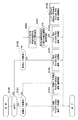
図2は、制御モード設定処理のフローチャートである。本処理は、制御部201、画像処理部204、露出制御部205、ストロボ制御部206及び表示制御部209の協働によって実行される。本処理に際し、ストロボ発光モード及び連続撮影モードはいずれも「オート」に設定されているものとする。
FIG. 2 is a flowchart of the control mode setting process. This process is executed by the cooperation of the
デジタルカメラ200において制御部201が撮影シーン検出を開始すると、まず、ステップS100では、画像処理部204が、入力されたデジタル画像信号を解析し、その解析結果に基づいて、制御部201は被写体が逆光であるか否かを判別する。ここでは例えば、得られた被写体画像の露出値が閾値より低い(暗い)場合等に逆光である(逆光シーンである)と判別される。その判別の結果、制御部201は、逆光でない場合は、ステップS101へ処理を進める一方、逆光である場合は処理をステップS102に進める。
When the
図3は、表示部210に表示されるシーンアイコン表示の例を示す図である。
FIG. 3 is a diagram illustrating an example of a scene icon display displayed on the
制御部201により検出される撮影シーンには、「通常撮影シーン」、「第1の撮影シーン」、「第2の撮影シーン」がある。「通常撮影シーン」は、ストロボ発光無しで単写撮影する撮影シーンである。「第1の撮影シーン」は、被写体が暗い等によりストロボ発光することが望ましい撮影シーンであり、本実施の形態では逆光シーンが例示される。「第2の撮影シーン」は、被写体が人物の笑顔、あるいは動いている子供であり、連続撮影することが望ましい撮影シーンであり、笑顔シーンと子供動きシーンとが例示される。
The shooting scenes detected by the
図3のシーンアイコン表示は、設定された撮影シーンをユーザに示すための表示であり、制御部201が検出した撮影シーンがそのまま表示されるとは限らない。本実施の形態では図3(a)〜(d)について説明し、図3(e)、(f)については第2の実施の形態で後述する。
The scene icon display in FIG. 3 is a display for showing the set shooting scene to the user, and the shooting scene detected by the
図2に戻り、ステップS101では、画像処理部204が、入力されたデジタル画像信号を解析し、その解析結果に基づいて、制御部201は、被写体が人物の笑顔、あるいは動いている子供であるかどうかを判別する。その判別の結果、制御部201は、人物の笑顔でなく且つ動いている子供でもない場合は、撮影シーンとして、第1の撮影シーンでも第2の撮影シーンでもない通常撮影シーンを検出したものとして、処理をステップS103へ進める。一方、制御部201は、人物の笑顔または動いている子供のいずれかである場合は、撮影シーンとして第2の撮影シーンを検出したものとして、処理をステップS104へ進める。
Returning to FIG. 2, in step S <b> 101, the
ステップS103では、図3(a)に示すように、制御部201は、撮影シーンが通常撮影シーンである旨を示す「通常撮影シーンアイコン」を表示部210に表示させるよう制御する。さらに、制御部201は、制御モードとしては、ストロボ発光モードを「非発光」、連続撮影モードを「一枚撮影」に設定する。
In step S103, as shown in FIG. 3A, the
ステップS104では、図3(c)、(d)に示すように、制御部201は、ステップS101で判別した結果に応じて、「笑顔シーンアイコン」または「子供動きシーンアイコン」を表示部210に表示させるよう制御する。さらに、制御部201は、制御モードとしては、ストロボ発光モードを「非発光」、連続撮影モードを「連続撮影」に設定する。
In step S104, as shown in FIGS. 3C and 3D, the
例えば、制御部201は、笑顔シーンと判定した場合は、高速に連続撮影を行い、各画像におけるピントや目瞑り具合、笑顔の度合い等を総合的に判断し、最も好ましい画像を1枚だけ残す動作となるよう制御する(図3(c))。また、制御部201は、子供動きシーンと判定した場合は、所定のコマ速で連続撮影を行い、動きのある様々な画像を残す動作となるよう制御する(図3(d))。
For example, when determining that the scene is a smiling scene, the
ステップS102では、画像処理部204が、入力されたデジタル画像信号を解析し、その解析結果に基づいて、制御部201は、被写体が人物の笑顔、あるいは動いている子供であるかどうかを判別する。その判別の結果、制御部201は、人物の笑顔でなく且つ動いている子供でもない場合は、撮影シーンとして第1の撮影シーンを検出し且つ第2の撮影シーンを検出しなかったものとして、処理をステップS105へ進める。一方、制御部201は、人物の笑顔または動いている子供のいずれかである場合は、撮影シーンとして第1の撮影シーン及び第2の撮影シーンを共に検出したものとして、処理をステップS106へ進める。
In step S102, the
ステップS105では、図3(b)に示すように、制御部201は、「逆光シーンアイコン」を表示部210に表示させるよう制御する。さらに、制御部201は、制御モードとしては、ストロボ発光モードを「発光」、連続撮影モードを「一枚撮影」に設定する。ストロボ発光で単写撮影をすることにより、逆光の被写体でも適切な露出の画像を残すことが可能となる。
In step S105, as shown in FIG. 3B, the
ステップS106では、図3(b)に示すように、第1、第2の撮影シーンが検出された状態であるが、制御部201は、ステップS105と同様に、「逆光シーンアイコン」を表示部210に表示させるよう制御する。さらに、制御部201は、制御モードとしては、ストロボ発光モードを「発光」、連続撮影モードを「一枚撮影」に設定する。
In step S106, as shown in FIG. 3B, the first and second shooting scenes are detected, but the
ステップS106でこのように制御するのは、仮にストロボ発光での連続撮影を設定してしまうと、撮影ごとにストロボ充電完了を待つ必要があり、所定のコマ速での連続撮影が実現できないからである。例えば、「笑顔」シーンでは高速に連続撮影を行い、最も好ましい表情となる瞬間を残さなければならない。その場合にコマ速の遅い連続撮影としたのでは所望のタイミングで撮影できないだけでなく、ユーザはいつ撮影が終了するのかわからず、カメラを被写体に向けたまま待つ必要が生じる。また、ストロボ非発光での連続撮影を設定したとすると、所望のコマ速での連続撮影は可能であるが、逆光のため暗い露出の画像しか得ることができない。そこで、ここではストロボ発光での一枚撮影を行い、1枚だけでも適切な露出の画像を得ることを優先する。 The reason for controlling in this way in step S106 is that if continuous shooting with flash emission is set, it is necessary to wait for the completion of flash charging for each shooting, and continuous shooting at a predetermined frame speed cannot be realized. is there. For example, in a “smile” scene, continuous shooting must be performed at high speed, leaving the moment when the most desirable facial expression is obtained. In this case, if continuous shooting is performed at a low frame speed, it is not only impossible to shoot at a desired timing, but the user does not know when shooting is finished, and needs to wait with the camera facing the subject. If continuous shooting without flash is set, continuous shooting at a desired frame speed is possible, but only a dark exposure image can be obtained due to backlight. Therefore, here, priority is given to taking an image with strobe light emission and obtaining an image with appropriate exposure even with only one image.
本実施の形態によれば、第1の撮影シーンが検出され且つ第2の撮影シーンが検出されない場合は、制御モードはストロボ発光且つ一枚撮影に設定される。また、第1の撮影シーンが検出されず且つ第2の撮影シーンが検出された場合は、制御モードはストロボ非発光且つ連続撮影に設定される。さらに、第1の撮影シーン及び第2の撮影シーンが共に検出された場合は、制御モードはストロボ発光且つ一枚撮影に設定される。これにより、ストロボ発光及び連写を撮影シーンに応じて設定し、適切な露出及びタイミングでの撮像画像を得ることができる。 According to the present embodiment, when the first shooting scene is detected and the second shooting scene is not detected, the control mode is set to strobe light emission and single shooting. When the first shooting scene is not detected and the second shooting scene is detected, the control mode is set to non-flash emission and continuous shooting. Further, when both the first shooting scene and the second shooting scene are detected, the control mode is set to strobe light emission and single image shooting. Thereby, strobe emission and continuous shooting can be set according to the shooting scene, and a captured image with appropriate exposure and timing can be obtained.
また、連続撮影がされる際には、ストロボ非発光となり充電待ちが生じないので、所定のコマ速が保証され、撮影がいつ終了するのかをユーザが認知しやすい。 Further, when continuous shooting is performed, the strobe is not lighted and no waiting for charging occurs, so that a predetermined frame speed is guaranteed, and the user can easily recognize when shooting ends.
また、第1の撮影シーン及び第2の撮影シーンが共に検出された場合であっても、制御モードがストロボ発光且つ一枚撮影に設定されて、撮影シーンが第1の撮影シーンである旨が表示される。これにより、撮影で実際に動作する制御モードをユーザが把握しやすい。 Further, even when both the first shooting scene and the second shooting scene are detected, the control mode is set to strobe light emission and single shooting, and the shooting scene is the first shooting scene. Is displayed. This makes it easy for the user to grasp the control mode that actually operates during shooting.
(第2の実施の形態)
上述した第1の実施の形態では、第1の撮影シーン及び第2の撮影シーンが共に検出された場合は、制御モードの設定を、結果として一律に、第1の撮影シーンのみが検出された場合と同様とした。これに対し本発明の第2の実施の形態では、設定した連写枚数及びコマ速でのストロボ発光を用いた連続撮影が実現可能か否かによって制御モードを設定する。従って、図2に代えて図4を用いて本実施の形態を説明する。
(Second Embodiment)
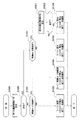
In the first embodiment described above, when both the first shooting scene and the second shooting scene are detected, the setting of the control mode is set uniformly, and as a result, only the first shooting scene is detected. Same as the case. On the other hand, in the second embodiment of the present invention, the control mode is set depending on whether or not continuous shooting using the set continuous shooting number and the strobe emission at the frame speed is feasible. Therefore, this embodiment will be described with reference to FIG. 4 instead of FIG.
図4は、第2の実施の形態における制御モード設定処理のフローチャートである。 FIG. 4 is a flowchart of the control mode setting process in the second embodiment.
図4のステップS100〜S106の処理については、図2のステップS100〜S106と同様である。 The processes in steps S100 to S106 in FIG. 4 are the same as steps S100 to S106 in FIG.
ステップS102の判別の結果、制御部201は、人物の笑顔または動いている子供のいずれかである場合は、撮影シーンとして第1の撮影シーン及び第2の撮影シーンを検出したものとして、処理をステップS400へ進める。
As a result of the determination in step S102, the
ステップS400では、制御部201は、ステップS102で検出した撮影シーンに応じた連続撮影における連写枚数及びコマ速を設定する。例えば、「笑顔」シーンと判定した場合は、最も好ましい表情となる瞬間を残すために、早いコマ速が要求される。また、「子供動き」シーンと判定した場合は、子供の動きのある様々なシーンを残すために、「笑顔」シーンより遅いコマ速が要求される。このように撮影シーンに応じて異なる所望の連写枚数及びコマ速をここで求め、設定しておく。
In step S400, the
次に、ステップS401では、制御部201は、ステップS400で設定した連写枚数及びコマ速でのストロボ発光を用いた連続撮影(以下、「発光連写」と略記する)が実現可能か否かを判定する。
Next, in step S401, the
ここでは判定手法の一例として、制御部201は、外部ストロボ発光部208の利用可否によって上記発光連写が実現可能か否かを判定する。すなわち、外部ストロボ発光部208が利用可能/利用不可能な場合は、上記発光連写が実現可能/実現不可能と判定する。具体的には、外部ストロボ発光部208が装着されているか否かを検出し、外部ストロボ発光部208が装着されていれば、短い充電時間で発光することが可能であるため、ストロボ発光での連続撮影が実現可能であると判定する。
Here, as an example of the determination method, the
あるいは他の判定手法として、制御部201は、設定されたコマ速とストロボ発光のための充電装置(不図示)の充電に要する時間とに基づいて、上記発光連写が実現可能か否かを判定するようにしてもよい。すなわち、制御部201は、所望のコマ速が「子供動き」シーンのように比較的遅い場合は、ストロボ充電時間を十分に確保できるため、ストロボ発光での連続撮影が実現可能であると判定する。または、制御部201は、内蔵ストロボ発光部207または外部ストロボ発光部208のうち利用される方のストロボ充電時間をストロボ制御部206により取得する。そして、ストロボ充電にかかる時間が所望のコマ速より短ければ、ストロボ発光での連続撮影が実現可能であると判定する。
Alternatively, as another determination method, the
あるいはさらに他の判定手法として、制御部201は、設定された連写枚数とストロボ発光のための充電電圧とに基づいて、上記発光連写が実現可能か否かを判定するようにしてもよい。すなわち、制御部201は、内蔵ストロボ発光部207または外部ストロボ発光部208のうち利用される方の現在のストロボ充電電圧が、所望の発光量及び連写枚数での発光に足りるのであれば、ストロボ発光での連続撮影が実現可能であると判定する。
Alternatively, as yet another determination method, the
ステップS401の判別の結果、制御部201は、上記発光連写が実現不可能の場合は処理をステップS106に進める一方、実現可能の場合は処理をステップS402に進める。
As a result of the determination in step S401, the
ステップS402では、図3(e)、(f)に示すように、ステップS102で検出した撮影シーンに応じた「逆光&笑顔」または「逆光&子供動き」のシーンアイコンを表示部210に表示させるよう制御する。さらに、制御部201は、制御モードとしては、ストロボ発光モードを「発光」、連続撮影モードを「連続撮影」に設定する。
In step S402, as shown in FIGS. 3E and 3F, a scene icon of “backlight & smile” or “backlight & child movement” corresponding to the shooting scene detected in step S102 is displayed on the
従って、例えば、「逆光&笑顔」シーンと判定された場合は、高速にストロボ発光での連続撮影を行い、各画像におけるピントや目瞑り具合、笑顔の度合い等を総合的に判断し、最も好ましい画像を1枚だけ残すこと動作となる。また、「逆光&子供動き」シーンと判定された場合は、所定のコマ速でストロボ発光での連続撮影を行い、動きのある様々な画像を残す動作となる。 Therefore, for example, when it is determined that the scene is “backlit & smiling”, it is most preferable to perform continuous shooting with high-speed strobe light and comprehensively determine the focus, eye meditation, smile level, etc. in each image. The operation is to leave only one image. If it is determined that the scene is “backlight & child movement”, the continuous shooting is performed with the flash emission at a predetermined frame speed, and various moving images are left.
本実施の形態によれば、ストロボ発光及び連写を撮影シーンに応じて設定し、適切な露出及びタイミングでの撮像画像を得ることに関し、第1の実施の形態と同様の効果を奏することができる。 According to the present embodiment, strobe light emission and continuous shooting are set according to the shooting scene, and an effect similar to that of the first embodiment can be obtained with respect to obtaining a captured image with appropriate exposure and timing. it can.
また、第1、第2の撮影シーンが共に検出された場合であっても、外部ストロボ発光部208の利用可否等によって発光連写が実現可能と判定できれば発光連写を行えるので、利便性が高まる。
Further, even when both the first and second shooting scenes are detected, if it can be determined that continuous light emission can be realized based on the availability of the external strobe
また、第1、第2の撮影シーンが共に検出された場合に、制御モードがストロボ発光に設定されたときは、撮影シーンが第1の撮影シーンである旨が表示されることで、制御モードを把握しやすい点は第1の実施の形態と同様である。 When both the first and second shooting scenes are detected and the control mode is set to strobe light emission, the fact that the shooting scene is the first shooting scene is displayed. The point that it is easy to grasp is the same as in the first embodiment.
(第3の実施の形態)
上述した第1の実施の形態では、第1、第2の撮影シーンが共に検出された場合は、制御モードの設定を、結果として一律に、第1の撮影シーンのみが検出された場合と同様とした。これに対し本発明の第3の実施の形態では、逆光であってもその程度が大きくない場合は、連続撮影を確保できるようにする。従って、図2に代えて図5を用いて本実施の形態を説明する。
(Third embodiment)
In the first embodiment described above, when both the first and second shooting scenes are detected, the setting of the control mode is uniformly set as a result, as in the case where only the first shooting scene is detected. It was. On the other hand, in the third embodiment of the present invention, continuous shooting can be ensured if the degree of backlighting is not large. Therefore, the present embodiment will be described with reference to FIG. 5 instead of FIG.
図5は、第3の実施の形態における制御モード設定処理のフローチャートである。 FIG. 5 is a flowchart of the control mode setting process in the third embodiment.
図5のステップS100〜S106の処理については、図2のステップS100〜S106と同様である。 The processing in steps S100 to S106 in FIG. 5 is the same as that in steps S100 to S106 in FIG.
まず、ステップS500では、制御部201は、逆光判別(ステップS100)において使用する第1の露出閾値E1を設定する。ステップS100で実行される逆光判別では、制御部201は、画像処理部204により得られた被写体の露出値が、第1の露出閾値E1を下回る(暗い)か否かによって、被写体が逆光であるか否かを判別する。従って、被写体の露出値<E1であるとき、逆光シーンであると判別する。
First, in step S500, the
ステップS102の判別の結果、制御部201は、人物の笑顔または動いている子供のいずれかである場合は、撮影シーンとして第1の撮影シーン及び第2の撮影シーンを検出したものとして、処理をステップS501へ進める。
As a result of the determination in step S102, the
ステップS501では、制御部201は、逆光判別(ステップS502)において使用する第2の露出閾値E2を設定する。ここで、第2の露出閾値E2は、第1の露出閾値E1より低い値(暗い値)である。
In step S501, the
ステップS502では、制御部201は、画像処理部204により得られた被写体の露出値が、第2の露出閾値E2を下回る(暗い)か否かによって、被写体が逆光であるか否かを判別する。従って、被写体の露出値<E2であるとき、逆光シーンであると判別する。その判別の結果、制御部201は、逆光でない場合は、ステップS104へ処理を進める一方、逆光である場合は処理をステップS106に進める。
In step S502, the
すなわち、第1の露出閾値E1との比較により、逆光と一旦判定された場合においても、人物の笑顔や動いている子供のような、連続撮影が望ましい第2の撮影シーンが同時に判定されたときには、より厳しい条件により逆光判別をステップS502でやり直す。 That is, when it is determined that backlighting is once determined by comparison with the first exposure threshold E1, a second shooting scene that is desirable for continuous shooting, such as a smiling face of a person or a moving child, is simultaneously determined. The backlight discrimination is performed again in step S502 under more severe conditions.
ステップS502からステップS104に進んだ場合は、逆光の程度が大きくないとして、ストロボ非発光にされるが所望のコマ速での連続撮影は確保されることになる。 When the process proceeds from step S502 to step S104, it is assumed that the degree of backlighting is not large, and the strobe is not emitted, but continuous shooting at a desired frame speed is ensured.
ただし、その際には、各画像が暗過ぎる露出の画像とならないように、露出制御部205により絞り、シャッター速度、ISO感度等を調整する。
However, in that case, the
ステップS502で被写体の露出値が第2の露出閾値E2を下回る場合、すなわち露出制御部205の制御では適正な露出が得られないレベルの場合にのみ逆光であると判別され、ステップS106でストロボ発光での一枚撮影が行われることになる。
If the exposure value of the subject is lower than the second exposure threshold value E2 in step S502, that is, if the
本実施の形態によれば、ストロボ発光及び連写を撮影シーンと露出値とに応じて設定するので、適切な露出及びタイミングでの撮像画像を得ることに関し、第1の実施の形態と同様の効果を奏することができる。 According to the present embodiment, strobe light emission and continuous shooting are set according to the shooting scene and the exposure value, so that it is the same as in the first embodiment regarding obtaining a captured image at an appropriate exposure and timing. There is an effect.
また、第1、第2の撮影シーンが共に検出された場合であっても、逆光のレベルが高くない場合は、ストロボ非発光にした連続撮影が実現されるので、利便性が高まる。 Further, even when both the first and second shooting scenes are detected, if the backlight level is not high, continuous shooting without using the strobe light is realized, so that convenience is improved.
また、第1、第2の撮影シーンが共に検出された場合に、制御モードがストロボ発光に設定されたときは、撮影シーンが第1の撮影シーンである旨が表示されることで、制御モードを把握しやすい点は第1の実施の形態と同様である。 When both the first and second shooting scenes are detected and the control mode is set to strobe light emission, the fact that the shooting scene is the first shooting scene is displayed. The point that it is easy to grasp is the same as in the first embodiment.
以上、本発明をその好適な実施形態に基づいて詳述してきたが、本発明はこれら特定の実施形態に限られるものではなく、この発明の要旨を逸脱しない範囲の様々な形態も本発明に含まれる。上述の実施形態の一部を適宜組み合わせてもよい。 Although the present invention has been described in detail based on preferred embodiments thereof, the present invention is not limited to these specific embodiments, and various forms within the scope of the present invention are also included in the present invention. included. A part of the above-described embodiments may be appropriately combined.
なお、ストロボ発光をさせて撮影を行うべき第1の撮影シーン、連続撮影を行うべき第2の撮影シーンは、それぞれ例示した要素以外のものから検出されるようにしてもよい。 Note that the first shooting scene that should be shot with strobe light emission and the second shooting scene that should be shot continuously may be detected from elements other than those exemplified.
なお、本発明の適用はデジタルカメラに限らない。ストロボを用いた単写及び連写機能を有する撮像装置であればよく、ビデオカメラにも適用可能である。 The application of the present invention is not limited to a digital camera. Any imaging device having a single shooting function and a continuous shooting function using a strobe may be used, and the present invention can also be applied to a video camera.
201 制御部
203 撮像部
210 表示部
Claims (3)
前記撮像手段により得られる被写体画像から、ストロボ発光をさせて撮影を行うべき第1の撮影シーンまたは連続撮影を行うべき第2の撮影シーンをそれぞれ撮影シーンとして検出する検出手段と、
前記検出手段により検出された撮影シーンに応じて、ストロボ発光またはストロボ非発光のいずれとするか、及び、連続撮影または一枚撮影のいずれとするかを制御モードとして設定して撮影を制御する制御手段とを有し、
前記検出手段は、前記得られる被写体画像の露出値が第1の露出閾値を下回る場合は、前記第1の撮影シーンであることを検出し、
前記制御手段は、
前記検出手段により前記第1の撮影シーンが検出され且つ前記第2の撮影シーンが検出されない場合は前記制御モードをストロボ発光且つ一枚撮影に設定し、
前記検出手段により前記第1の撮影シーンが検出されず且つ前記第2の撮影シーンが検出された場合は前記制御モードをストロボ非発光且つ連続撮影に設定し、
前記検出手段により前記第1の撮影シーン及び前記第2の撮影シーンが共に検出された場合においては、前記得られる被写体画像の露出値が前記第1の露出閾値より低い第2の露出閾値を下回るときは前記制御モードをストロボ発光且つ一枚撮影に設定し、前記得られる被写体画像の露出値が前記第2の露出閾値を下回らないときは前記制御モードをストロボ非発光且つ連続撮影に設定することを特徴とする撮像装置。 Imaging means;
Detection means for detecting, as a shooting scene, a first shooting scene that should be shot with a strobe light emission or a second shooting scene that should be shot continuously from the subject image obtained by the imaging means;
Control for controlling shooting by setting as a control mode whether to use a strobe light emission or a strobe non-light emission depending on the shooting scene detected by the detection means, and to select either continuous shooting or single shooting. Means,
The detection means detects that the scene is the first shooting scene when the exposure value of the obtained subject image is lower than a first exposure threshold;
The control means includes
When the first shooting scene is detected by the detecting means and the second shooting scene is not detected, the control mode is set to flash emission and single shooting,
When the first shooting scene is not detected by the detection means and the second shooting scene is detected, the control mode is set to non-flash and continuous shooting,
When both the first shooting scene and the second shooting scene are detected by the detection means, the exposure value of the obtained subject image is lower than a second exposure threshold lower than the first exposure threshold. When the control mode is set to flash emission and single shooting, and when the exposure value of the obtained subject image does not fall below the second exposure threshold, the control mode is set to flash non-flash and continuous shooting. An imaging apparatus characterized by the above.
前記検出ステップにより検出された撮影シーンに応じて、ストロボ発光またはストロボ非発光のいずれとするか、及び、連続撮影または一枚撮影のいずれとするかを制御モードとして設定して撮影を制御する制御ステップとを有し、
前記検出ステップは、前記得られる被写体画像の露出値が第1の露出閾値を下回る場合は、前記第1の撮影シーンであることを検出し、
前記制御ステップは、
前記検出ステップにより前記第1の撮影シーンが検出され且つ前記第2の撮影シーンが検出されない場合は前記制御モードをストロボ発光且つ一枚撮影に設定し、
前記検出ステップにより前記第1の撮影シーンが検出されず且つ前記第2の撮影シーンが検出された場合は前記制御モードをストロボ非発光且つ連続撮影に設定し、
前記検出ステップにより前記第1の撮影シーン及び前記第2の撮影シーンが共に検出された場合においては、前記得られる被写体画像の露出値が前記第1の露出閾値より低い第2の露出閾値を下回るときは前記制御モードをストロボ発光且つ一枚撮影に設定し、前記得られる被写体画像の露出値が前記第2の露出閾値を下回らないときは前記制御モードをストロボ非発光且つ連続撮影に設定することを特徴とする撮像装置の制御方法。
A detection step of detecting, from the subject image obtained by the imaging means, a first shooting scene that should be shot with strobe light emission or a second shooting scene that should be shot continuously as a shooting scene;
Control for controlling shooting by setting as a control mode whether to use flash or non-flash, and continuous shooting or single shooting according to the shooting scene detected in the detection step. And having steps
In the detection step, when the exposure value of the obtained subject image is lower than a first exposure threshold, it is detected that the scene is the first shooting scene,
The control step includes
When the first shooting scene is detected by the detection step and the second shooting scene is not detected, the control mode is set to flash emission and single shooting,
If the first shooting scene is not detected by the detection step and the second shooting scene is detected, the control mode is set to non-flash and continuous shooting,
When both the first shooting scene and the second shooting scene are detected by the detection step, an exposure value of the obtained subject image is lower than a second exposure threshold lower than the first exposure threshold. When the control mode is set to flash emission and single shooting, and when the exposure value of the obtained subject image does not fall below the second exposure threshold, the control mode is set to flash non-flash and continuous shooting. A method for controlling an image pickup apparatus.
Priority Applications (1)
| Application Number | Priority Date | Filing Date | Title |
|---|---|---|---|
| JP2011288270A JP5963440B2 (en) | 2011-12-28 | 2011-12-28 | Imaging apparatus and control method thereof |
Applications Claiming Priority (1)
| Application Number | Priority Date | Filing Date | Title |
|---|---|---|---|
| JP2011288270A JP5963440B2 (en) | 2011-12-28 | 2011-12-28 | Imaging apparatus and control method thereof |
Publications (3)
| Publication Number | Publication Date |
|---|---|
| JP2013137415A JP2013137415A (en) | 2013-07-11 |
| JP2013137415A5 JP2013137415A5 (en) | 2015-02-19 |
| JP5963440B2 true JP5963440B2 (en) | 2016-08-03 |
Family
ID=48913199
Family Applications (1)
| Application Number | Title | Priority Date | Filing Date |
|---|---|---|---|
| JP2011288270A Expired - Fee Related JP5963440B2 (en) | 2011-12-28 | 2011-12-28 | Imaging apparatus and control method thereof |
Country Status (1)
| Country | Link |
|---|---|
| JP (1) | JP5963440B2 (en) |
Families Citing this family (1)
| Publication number | Priority date | Publication date | Assignee | Title |
|---|---|---|---|---|
| CN111357275B (en) * | 2017-09-20 | 2022-02-08 | 深圳传音通讯有限公司 | Flash control method, mobile terminal and computer-readable storage medium |
Family Cites Families (6)
| Publication number | Priority date | Publication date | Assignee | Title |
|---|---|---|---|---|
| JP2000047300A (en) * | 1998-07-31 | 2000-02-18 | Olympus Optical Co Ltd | Stroboscope system for camera |
| JP3473552B2 (en) * | 2000-06-15 | 2003-12-08 | ミノルタ株式会社 | Digital still camera |
| JP2005142774A (en) * | 2003-11-05 | 2005-06-02 | Kyocera Corp | Imaging device |
| JP2007208412A (en) * | 2006-01-31 | 2007-08-16 | Fujifilm Corp | Imaging device |
| JP2008276041A (en) * | 2007-05-02 | 2008-11-13 | Casio Comput Co Ltd | Imaging apparatus, imaging control program, and imaging control method |
| JP5083090B2 (en) * | 2007-09-18 | 2012-11-28 | ソニー株式会社 | Display control apparatus, imaging apparatus, display control method, and program |
-
2011
- 2011-12-28 JP JP2011288270A patent/JP5963440B2/en not_active Expired - Fee Related
Also Published As
| Publication number | Publication date |
|---|---|
| JP2013137415A (en) | 2013-07-11 |
Similar Documents
| Publication | Publication Date | Title |
|---|---|---|
| JP4884417B2 (en) | Portable electronic device and control method thereof | |
| CN103986853B (en) | Filming apparatus and image pickup method | |
| CN101790047A (en) | Image processing device, image management device, and image management method and program | |
| JP4422667B2 (en) | Imaging apparatus and imaging method | |
| JP2013135341A (en) | Image processing device and image processing method, program, and storage medium | |
| KR20110055243A (en) | Digital recording device, its control method and recording medium storing program for executing same | |
| JP2017123020A (en) | Image processing apparatus, imaging apparatus, control method thereof, and program | |
| CN106488113B (en) | Image pickup device, recording instruction device, image recording method, and recording instruction method | |
| JP7713802B2 (en) | Electronic device and control method thereof | |
| JP5963440B2 (en) | Imaging apparatus and control method thereof | |
| JP4879840B2 (en) | Digital camera and control method thereof | |
| JP6370146B2 (en) | Image processing apparatus and control method thereof | |
| JP2015114880A (en) | Display device with touch panel | |
| JP2012034146A (en) | Electronic apparatus and program | |
| JP6335497B2 (en) | Imaging device, control method thereof, and control program | |
| KR101630295B1 (en) | A digital photographing apparatus, a method for controlling the same, and a computer-readable medium | |
| JP5261769B2 (en) | Imaging apparatus and group photo shooting support program | |
| JP5784316B2 (en) | Valve imaging device and valve imaging method | |
| TW201040882A (en) | Detection method of the stability of digital photography device, and the digital photography device | |
| JP6432290B2 (en) | Imaging apparatus, imaging control method, and program | |
| JP6688086B2 (en) | Imaging device, control method thereof, and program | |
| JP2014011502A (en) | Image pick-up device and control method thereof | |
| JP2010134176A (en) | Photographing device and photographing method | |
| JP6432289B2 (en) | Imaging apparatus, imaging control method, and program | |
| JP4844340B2 (en) | Camera and shooting program |
Legal Events
| Date | Code | Title | Description |
|---|---|---|---|
| A521 | Request for written amendment filed |
Free format text: JAPANESE INTERMEDIATE CODE: A523 Effective date: 20141222 |
|
| A621 | Written request for application examination |
Free format text: JAPANESE INTERMEDIATE CODE: A621 Effective date: 20141222 |
|
| A977 | Report on retrieval |
Free format text: JAPANESE INTERMEDIATE CODE: A971007 Effective date: 20151120 |
|
| A131 | Notification of reasons for refusal |
Free format text: JAPANESE INTERMEDIATE CODE: A131 Effective date: 20151201 |
|
| A521 | Request for written amendment filed |
Free format text: JAPANESE INTERMEDIATE CODE: A523 Effective date: 20160127 |
|
| TRDD | Decision of grant or rejection written | ||
| A01 | Written decision to grant a patent or to grant a registration (utility model) |
Free format text: JAPANESE INTERMEDIATE CODE: A01 Effective date: 20160531 |
|
| A61 | First payment of annual fees (during grant procedure) |
Free format text: JAPANESE INTERMEDIATE CODE: A61 Effective date: 20160628 |
|
| R151 | Written notification of patent or utility model registration |
Ref document number: 5963440 Country of ref document: JP Free format text: JAPANESE INTERMEDIATE CODE: R151 |
|
| LAPS | Cancellation because of no payment of annual fees |