JP2016207597A - 電池収容装置 - Google Patents
電池収容装置 Download PDFInfo
- Publication number
- JP2016207597A JP2016207597A JP2015091154A JP2015091154A JP2016207597A JP 2016207597 A JP2016207597 A JP 2016207597A JP 2015091154 A JP2015091154 A JP 2015091154A JP 2015091154 A JP2015091154 A JP 2015091154A JP 2016207597 A JP2016207597 A JP 2016207597A
- Authority
- JP
- Japan
- Prior art keywords
- battery
- recess
- battery housing
- jig
- wall
- Prior art date
- Legal status (The legal status is an assumption and is not a legal conclusion. Google has not performed a legal analysis and makes no representation as to the accuracy of the status listed.)
- Granted
Links
- 210000000078 claw Anatomy 0.000 claims description 24
- 230000001681 protective effect Effects 0.000 claims description 8
- 230000001105 regulatory effect Effects 0.000 abstract 1
- 241000755266 Kathetostoma giganteum Species 0.000 description 4
- 239000000470 constituent Substances 0.000 description 1
- 230000000694 effects Effects 0.000 description 1
- 239000002184 metal Substances 0.000 description 1
- 230000004048 modification Effects 0.000 description 1
- 238000012986 modification Methods 0.000 description 1
- 229910000679 solder Inorganic materials 0.000 description 1
- 229920003002 synthetic resin Polymers 0.000 description 1
- 239000000057 synthetic resin Substances 0.000 description 1
Images



Classifications
-
- H—ELECTRICITY
- H01—ELECTRIC ELEMENTS
- H01M—PROCESSES OR MEANS, e.g. BATTERIES, FOR THE DIRECT CONVERSION OF CHEMICAL ENERGY INTO ELECTRICAL ENERGY
- H01M50/00—Constructional details or processes of manufacture of the non-active parts of electrochemical cells other than fuel cells, e.g. hybrid cells
- H01M50/20—Mountings; Secondary casings or frames; Racks, modules or packs; Suspension devices; Shock absorbers; Transport or carrying devices; Holders
-
- Y—GENERAL TAGGING OF NEW TECHNOLOGICAL DEVELOPMENTS; GENERAL TAGGING OF CROSS-SECTIONAL TECHNOLOGIES SPANNING OVER SEVERAL SECTIONS OF THE IPC; TECHNICAL SUBJECTS COVERED BY FORMER USPC CROSS-REFERENCE ART COLLECTIONS [XRACs] AND DIGESTS
- Y02—TECHNOLOGIES OR APPLICATIONS FOR MITIGATION OR ADAPTATION AGAINST CLIMATE CHANGE
- Y02E—REDUCTION OF GREENHOUSE GAS [GHG] EMISSIONS, RELATED TO ENERGY GENERATION, TRANSMISSION OR DISTRIBUTION
- Y02E60/00—Enabling technologies; Technologies with a potential or indirect contribution to GHG emissions mitigation
- Y02E60/10—Energy storage using batteries
Landscapes
- Chemical & Material Sciences (AREA)
- Chemical Kinetics & Catalysis (AREA)
- Electrochemistry (AREA)
- General Chemical & Material Sciences (AREA)
- Battery Mounting, Suspending (AREA)
Abstract
【解決手段】枠部30と、枠部30に囲まれるように形成された電池収容部10と、電池の下面に接触する電極切片41aと、を備えた電池収容装置100であって、電池収容部10の端部の近傍に、電池取り外し用の治具の先端を電池の下面側に案内する凹部20が設けられていると共に、凹部20の電池収容部10側の凹部底面23から上方向に壁部21が形成されている。このような構成によって、取り外し用の治具の先端が凹部20によって電池の下面側に案内されるとともに、差し込まれた治具の先端が壁部21に当接して押し止められ、治具の先端が電極切片41a側に滑り込むことを規制するため、治具が電極切片41aを損傷させることを防止することができる。
【選択図】図1
Description
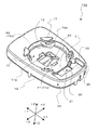
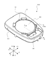
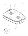
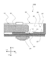
以下、本発明の実施形態について図面を参照しながら説明する。本実施形態に係る電池収容装置100は、例えば、キーレスエントリー装置に使用される携帯機内の電池収容装置に用いられる。尚、本実施の形態に係る電池収容装置100の用途については、これに限定されるものではなく適宜変更が可能である。本明細書では、特に断りの無い限り、各図面の+X側を右側、−X側を左側、+Y側を後側、−Y側を前側、+Z側を上側、−Z側を下側として説明する。
11 底面
11a 開口
13 側面
13a 開口
15 弾性爪
15a 上端
17 電池支持部
19 隙間
20 凹部
21 壁部
23 凹部底面
25 溝部
27 溝部底面
30 枠部
31 保護壁
33 ガイド部
35 側壁
37 前壁
38 基板取り付けガイド部
39 基板取り付け爪
40 回路部
41 第1電極
41a 電極切片
42 第2電極
42a 電極切片
43 押しボタン部材
45 電子回路
49 回路基板
61 電池
63 治具
65 マイナスドライバー
65a 先端部
65b 中間部
65c 取手部
67 コイン
67a コイン端部
67b コイン中間部
67c コイン端部
100 電池収容装置
Claims (4)
- 枠部と、前記枠部に囲まれるように形成された電池収容部と、電池の下面に接触する電極切片と、を備えた電池収容装置であって、
前記電池収容部の端部の近傍に、電池取り外し用の治具の先端を電池の下面側に案内する凹部が設けられていると共に、前記凹部の前記電池収容部側の凹部底面から上方向に壁部が形成されている、
ことを特徴とする電池収容装置。 - 前記電池収容部には、電池の縁部を保持する弾性爪が設けられており、前記弾性爪と前記凹部との間に保護壁を設けた、
ことを特徴とする請求項1に記載の電池収容装置。 - 前記壁部の幅よりも幅広の取り外し用の治具が前記凹部に差し込まれた時に当該取り外し用の治具を案内する一対のガイド部を、前記壁部の外側に設けた、
ことを特徴とする請求項1又は請求項2に記載の電池収容装置。 - 前記凹部の幅よりも幅広の溝部を前記凹部に隣接して形成すると共に、
前記壁部の幅よりも幅広の取り外し用の治具が当接可能な一対の側壁部を、前記溝部の溝部底面から上方向に形成した、
ことを特徴とする請求項1乃至請求項3のいずれかに記載の電池収容装置。
Priority Applications (2)
| Application Number | Priority Date | Filing Date | Title |
|---|---|---|---|
| JP2015091154A JP6531251B2 (ja) | 2015-04-28 | 2015-04-28 | 電池収容装置 |
| CN201610152701.6A CN106098985B (zh) | 2015-04-28 | 2016-03-17 | 电池容放装置 |
Applications Claiming Priority (1)
| Application Number | Priority Date | Filing Date | Title |
|---|---|---|---|
| JP2015091154A JP6531251B2 (ja) | 2015-04-28 | 2015-04-28 | 電池収容装置 |
Publications (2)
| Publication Number | Publication Date |
|---|---|
| JP2016207597A true JP2016207597A (ja) | 2016-12-08 |
| JP6531251B2 JP6531251B2 (ja) | 2019-06-19 |
Family
ID=57487260
Family Applications (1)
| Application Number | Title | Priority Date | Filing Date |
|---|---|---|---|
| JP2015091154A Active JP6531251B2 (ja) | 2015-04-28 | 2015-04-28 | 電池収容装置 |
Country Status (2)
| Country | Link |
|---|---|
| JP (1) | JP6531251B2 (ja) |
| CN (1) | CN106098985B (ja) |
Citations (3)
| Publication number | Priority date | Publication date | Assignee | Title |
|---|---|---|---|---|
| US4998888A (en) * | 1984-07-23 | 1991-03-12 | Sgs-Thomson Microelectronics, Inc. | Integrated circuit package with battery housing |
| JPH0817409A (ja) * | 1994-06-28 | 1996-01-19 | Sony Corp | 電子機器に装着される電池 |
| JP2009259666A (ja) * | 2008-04-18 | 2009-11-05 | Ishida Co Ltd | ボタン電池の取り外し構造、電子機器及びボタン電池の取り外し用治具 |
Family Cites Families (2)
| Publication number | Priority date | Publication date | Assignee | Title |
|---|---|---|---|---|
| US5654111A (en) * | 1994-06-28 | 1997-08-05 | Sony Corporation | Electronic device having a battery and a battery therefor |
| CN201708424U (zh) * | 2010-04-19 | 2011-01-12 | 富士康(昆山)电脑接插件有限公司 | 电连接器组件 |
-
2015
- 2015-04-28 JP JP2015091154A patent/JP6531251B2/ja active Active
-
2016
- 2016-03-17 CN CN201610152701.6A patent/CN106098985B/zh active Active
Patent Citations (3)
| Publication number | Priority date | Publication date | Assignee | Title |
|---|---|---|---|---|
| US4998888A (en) * | 1984-07-23 | 1991-03-12 | Sgs-Thomson Microelectronics, Inc. | Integrated circuit package with battery housing |
| JPH0817409A (ja) * | 1994-06-28 | 1996-01-19 | Sony Corp | 電子機器に装着される電池 |
| JP2009259666A (ja) * | 2008-04-18 | 2009-11-05 | Ishida Co Ltd | ボタン電池の取り外し構造、電子機器及びボタン電池の取り外し用治具 |
Also Published As
| Publication number | Publication date |
|---|---|
| CN106098985B (zh) | 2019-06-28 |
| JP6531251B2 (ja) | 2019-06-19 |
| CN106098985A (zh) | 2016-11-09 |
Similar Documents
| Publication | Publication Date | Title |
|---|---|---|
| CN103294209B (zh) | 键盘装置、键盘保持装置以及信息输入装置 | |
| JP6599967B2 (ja) | 電子装置 | |
| US9331409B2 (en) | Electrical connection device | |
| KR101882622B1 (ko) | 전기 커넥터 | |
| JP6657981B2 (ja) | 電子機器の電池収納構造 | |
| US7641508B2 (en) | Battery connector with reinforcing members | |
| US20160133889A1 (en) | Battery holder | |
| JP2016149519A (ja) | 保持機構、及び保持機構を有する電子装置 | |
| JP2016207597A (ja) | 電池収容装置 | |
| JP5563547B2 (ja) | キーボードの取付構造 | |
| JP2009259666A (ja) | ボタン電池の取り外し構造、電子機器及びボタン電池の取り外し用治具 | |
| CN204108934U (zh) | 电气设备拆卸用附件以及电气设备组件 | |
| JP2020129594A (ja) | ユニット取付構造および電子機器 | |
| JP6032816B2 (ja) | 車両用キー装置 | |
| US20120154998A1 (en) | Electronic apparatus | |
| KR101589300B1 (ko) | 전기전자통신 소품 취부용 레일 절단기 | |
| JP6449067B2 (ja) | 多方向入力装置 | |
| JP2015195091A (ja) | 電子機器及び電子機器のボタン構造 | |
| JP2006253531A (ja) | 電気機器取付装置 | |
| CN118369657A (zh) | 盖部件和电子设备 | |
| CN102651405A (zh) | 电子装置及其红外线接收器 | |
| KR200291135Y1 (ko) | 슬라이딩 방식의 휴대폰 배터리 착탈장치 | |
| JP2010011720A (ja) | インバータ装置 | |
| JP4793937B2 (ja) | 電子部品接続治具 | |
| JP6004542B2 (ja) | Dinレール取付構造 |
Legal Events
| Date | Code | Title | Description |
|---|---|---|---|
| A621 | Written request for application examination |
Free format text: JAPANESE INTERMEDIATE CODE: A621 Effective date: 20171122 |
|
| A977 | Report on retrieval |
Free format text: JAPANESE INTERMEDIATE CODE: A971007 Effective date: 20181010 |
|
| A131 | Notification of reasons for refusal |
Free format text: JAPANESE INTERMEDIATE CODE: A131 Effective date: 20181204 |
|
| A521 | Request for written amendment filed |
Free format text: JAPANESE INTERMEDIATE CODE: A523 Effective date: 20190116 |
|
| TRDD | Decision of grant or rejection written | ||
| A01 | Written decision to grant a patent or to grant a registration (utility model) |
Free format text: JAPANESE INTERMEDIATE CODE: A01 Effective date: 20190402 |
|
| A61 | First payment of annual fees (during grant procedure) |
Free format text: JAPANESE INTERMEDIATE CODE: A61 Effective date: 20190404 |
|
| R150 | Certificate of patent or registration of utility model |
Ref document number: 6531251 Country of ref document: JP Free format text: JAPANESE INTERMEDIATE CODE: R150 |