JP2016198742A - Liquid treatment system, solution processing device and solution treatment method - Google Patents
Liquid treatment system, solution processing device and solution treatment method Download PDFInfo
- Publication number
- JP2016198742A JP2016198742A JP2015081964A JP2015081964A JP2016198742A JP 2016198742 A JP2016198742 A JP 2016198742A JP 2015081964 A JP2015081964 A JP 2015081964A JP 2015081964 A JP2015081964 A JP 2015081964A JP 2016198742 A JP2016198742 A JP 2016198742A
- Authority
- JP
- Japan
- Prior art keywords
- adsorption
- solution
- water
- solution processing
- porous ceramic
- Prior art date
- Legal status (The legal status is an assumption and is not a legal conclusion. Google has not performed a legal analysis and makes no representation as to the accuracy of the status listed.)
- Pending
Links
- 238000000034 method Methods 0.000 title claims abstract description 103
- 238000010129 solution processing Methods 0.000 title claims description 48
- 239000007788 liquid Substances 0.000 title description 7
- 239000000919 ceramic Substances 0.000 claims abstract description 204
- 238000001179 sorption measurement Methods 0.000 claims abstract description 193
- CBENFWSGALASAD-UHFFFAOYSA-N Ozone Chemical compound [O-][O+]=O CBENFWSGALASAD-UHFFFAOYSA-N 0.000 claims abstract description 156
- PNEYBMLMFCGWSK-UHFFFAOYSA-N aluminium oxide Inorganic materials [O-2].[O-2].[O-2].[Al+3].[Al+3] PNEYBMLMFCGWSK-UHFFFAOYSA-N 0.000 claims abstract description 49
- 230000007246 mechanism Effects 0.000 claims abstract description 8
- 239000012528 membrane Substances 0.000 claims description 126
- 239000000126 substance Substances 0.000 claims description 100
- 238000005192 partition Methods 0.000 claims description 33
- 238000001914 filtration Methods 0.000 claims description 21
- 238000004891 communication Methods 0.000 claims description 7
- XLYOFNOQVPJJNP-UHFFFAOYSA-N water Substances O XLYOFNOQVPJJNP-UHFFFAOYSA-N 0.000 abstract description 240
- 239000002156 adsorbate Substances 0.000 abstract description 25
- 239000003463 adsorbent Substances 0.000 description 191
- 239000007789 gas Substances 0.000 description 96
- 238000001223 reverse osmosis Methods 0.000 description 88
- 238000004140 cleaning Methods 0.000 description 64
- 238000002347 injection Methods 0.000 description 57
- 239000007924 injection Substances 0.000 description 57
- 239000013535 sea water Substances 0.000 description 57
- 239000000243 solution Substances 0.000 description 53
- 229920000057 Mannan Polymers 0.000 description 41
- 239000005416 organic matter Substances 0.000 description 33
- 238000011084 recovery Methods 0.000 description 33
- HEMHJVSKTPXQMS-UHFFFAOYSA-M Sodium hydroxide Chemical compound [OH-].[Na+] HEMHJVSKTPXQMS-UHFFFAOYSA-M 0.000 description 30
- 238000010612 desalination reaction Methods 0.000 description 30
- 239000007864 aqueous solution Substances 0.000 description 23
- 239000000463 material Substances 0.000 description 22
- 230000008569 process Effects 0.000 description 21
- 238000012545 processing Methods 0.000 description 21
- QTBSBXVTEAMEQO-UHFFFAOYSA-N Acetic acid Chemical compound CC(O)=O QTBSBXVTEAMEQO-UHFFFAOYSA-N 0.000 description 20
- 244000005700 microbiome Species 0.000 description 18
- 239000011148 porous material Substances 0.000 description 17
- 239000003899 bactericide agent Substances 0.000 description 16
- 238000005259 measurement Methods 0.000 description 15
- 238000000926 separation method Methods 0.000 description 15
- MHAJPDPJQMAIIY-UHFFFAOYSA-N Hydrogen peroxide Chemical compound OO MHAJPDPJQMAIIY-UHFFFAOYSA-N 0.000 description 13
- 238000002474 experimental method Methods 0.000 description 13
- 230000000844 anti-bacterial effect Effects 0.000 description 11
- 239000003638 chemical reducing agent Substances 0.000 description 11
- 238000005406 washing Methods 0.000 description 11
- 230000007423 decrease Effects 0.000 description 10
- 239000003792 electrolyte Substances 0.000 description 10
- 230000003472 neutralizing effect Effects 0.000 description 10
- 239000003002 pH adjusting agent Substances 0.000 description 10
- 235000011121 sodium hydroxide Nutrition 0.000 description 10
- 230000008859 change Effects 0.000 description 9
- 238000009287 sand filtration Methods 0.000 description 9
- 239000003206 sterilizing agent Substances 0.000 description 9
- 238000011033 desalting Methods 0.000 description 8
- 230000000694 effects Effects 0.000 description 8
- 238000011156 evaluation Methods 0.000 description 8
- LCPVQAHEFVXVKT-UHFFFAOYSA-N 2-(2,4-difluorophenoxy)pyridin-3-amine Chemical compound NC1=CC=CN=C1OC1=CC=C(F)C=C1F LCPVQAHEFVXVKT-UHFFFAOYSA-N 0.000 description 7
- 239000003513 alkali Substances 0.000 description 7
- 238000000354 decomposition reaction Methods 0.000 description 7
- 238000004519 manufacturing process Methods 0.000 description 7
- 229910052751 metal Inorganic materials 0.000 description 7
- 239000002184 metal Substances 0.000 description 7
- 229910044991 metal oxide Inorganic materials 0.000 description 7
- 150000004706 metal oxides Chemical class 0.000 description 7
- 238000002203 pretreatment Methods 0.000 description 7
- CHQMHPLRPQMAMX-UHFFFAOYSA-L sodium persulfate Substances [Na+].[Na+].[O-]S(=O)(=O)OOS([O-])(=O)=O CHQMHPLRPQMAMX-UHFFFAOYSA-L 0.000 description 7
- FAPWRFPIFSIZLT-UHFFFAOYSA-M Sodium chloride Chemical compound [Na+].[Cl-] FAPWRFPIFSIZLT-UHFFFAOYSA-M 0.000 description 6
- 239000002253 acid Substances 0.000 description 6
- 239000004760 aramid Substances 0.000 description 6
- 229920003235 aromatic polyamide Polymers 0.000 description 6
- 239000003795 chemical substances by application Substances 0.000 description 6
- 229910052878 cordierite Inorganic materials 0.000 description 6
- JSKIRARMQDRGJZ-UHFFFAOYSA-N dimagnesium dioxido-bis[(1-oxido-3-oxo-2,4,6,8,9-pentaoxa-1,3-disila-5,7-dialuminabicyclo[3.3.1]nonan-7-yl)oxy]silane Chemical compound [Mg++].[Mg++].[O-][Si]([O-])(O[Al]1O[Al]2O[Si](=O)O[Si]([O-])(O1)O2)O[Al]1O[Al]2O[Si](=O)O[Si]([O-])(O1)O2 JSKIRARMQDRGJZ-UHFFFAOYSA-N 0.000 description 6
- 239000002699 waste material Substances 0.000 description 6
- 239000002351 wastewater Substances 0.000 description 6
- OKTJSMMVPCPJKN-UHFFFAOYSA-N Carbon Chemical compound [C] OKTJSMMVPCPJKN-UHFFFAOYSA-N 0.000 description 5
- 239000003242 anti bacterial agent Substances 0.000 description 5
- 229910052799 carbon Inorganic materials 0.000 description 5
- 239000013078 crystal Substances 0.000 description 5
- 239000012530 fluid Substances 0.000 description 5
- 230000001590 oxidative effect Effects 0.000 description 5
- 239000012466 permeate Substances 0.000 description 5
- 229920001282 polysaccharide Polymers 0.000 description 5
- 239000005017 polysaccharide Substances 0.000 description 5
- 150000004804 polysaccharides Chemical class 0.000 description 5
- 239000008400 supply water Substances 0.000 description 5
- 239000002344 surface layer Substances 0.000 description 5
- QAOWNCQODCNURD-UHFFFAOYSA-N Sulfuric acid Chemical compound OS(O)(=O)=O QAOWNCQODCNURD-UHFFFAOYSA-N 0.000 description 4
- XLOMVQKBTHCTTD-UHFFFAOYSA-N Zinc monoxide Chemical compound [Zn]=O XLOMVQKBTHCTTD-UHFFFAOYSA-N 0.000 description 4
- 230000002378 acidificating effect Effects 0.000 description 4
- 238000009295 crossflow filtration Methods 0.000 description 4
- 239000000645 desinfectant Substances 0.000 description 4
- 230000006866 deterioration Effects 0.000 description 4
- 238000007599 discharging Methods 0.000 description 4
- 239000013505 freshwater Substances 0.000 description 4
- 238000012423 maintenance Methods 0.000 description 4
- QSHDDOUJBYECFT-UHFFFAOYSA-N mercury Chemical compound [Hg] QSHDDOUJBYECFT-UHFFFAOYSA-N 0.000 description 4
- 229910052753 mercury Inorganic materials 0.000 description 4
- 239000004094 surface-active agent Substances 0.000 description 4
- UUIVKBHZENILKB-UHFFFAOYSA-N 2,2-dibromo-2-cyanoacetamide Chemical compound NC(=O)C(Br)(Br)C#N UUIVKBHZENILKB-UHFFFAOYSA-N 0.000 description 3
- ZAMOUSCENKQFHK-UHFFFAOYSA-N Chlorine atom Chemical compound [Cl] ZAMOUSCENKQFHK-UHFFFAOYSA-N 0.000 description 3
- 230000009471 action Effects 0.000 description 3
- 230000008901 benefit Effects 0.000 description 3
- 239000000460 chlorine Substances 0.000 description 3
- 229910052801 chlorine Inorganic materials 0.000 description 3
- 239000011248 coating agent Substances 0.000 description 3
- 238000000576 coating method Methods 0.000 description 3
- 238000005260 corrosion Methods 0.000 description 3
- 230000007797 corrosion Effects 0.000 description 3
- QWPPOHNGKGFGJK-UHFFFAOYSA-N hypochlorous acid Chemical compound ClO QWPPOHNGKGFGJK-UHFFFAOYSA-N 0.000 description 3
- 239000012535 impurity Substances 0.000 description 3
- 230000003993 interaction Effects 0.000 description 3
- 150000002500 ions Chemical class 0.000 description 3
- 239000007791 liquid phase Substances 0.000 description 3
- 230000002093 peripheral effect Effects 0.000 description 3
- 239000004576 sand Substances 0.000 description 3
- 239000004065 semiconductor Substances 0.000 description 3
- 239000011780 sodium chloride Substances 0.000 description 3
- 230000001954 sterilising effect Effects 0.000 description 3
- 238000003860 storage Methods 0.000 description 3
- 238000009423 ventilation Methods 0.000 description 3
- KIUKXJAPPMFGSW-DNGZLQJQSA-N (2S,3S,4S,5R,6R)-6-[(2S,3R,4R,5S,6R)-3-Acetamido-2-[(2S,3S,4R,5R,6R)-6-[(2R,3R,4R,5S,6R)-3-acetamido-2,5-dihydroxy-6-(hydroxymethyl)oxan-4-yl]oxy-2-carboxy-4,5-dihydroxyoxan-3-yl]oxy-5-hydroxy-6-(hydroxymethyl)oxan-4-yl]oxy-3,4,5-trihydroxyoxane-2-carboxylic acid Chemical compound CC(=O)N[C@H]1[C@H](O)O[C@H](CO)[C@@H](O)[C@@H]1O[C@H]1[C@H](O)[C@@H](O)[C@H](O[C@H]2[C@@H]([C@@H](O[C@H]3[C@@H]([C@@H](O)[C@H](O)[C@H](O3)C(O)=O)O)[C@H](O)[C@@H](CO)O2)NC(C)=O)[C@@H](C(O)=O)O1 KIUKXJAPPMFGSW-DNGZLQJQSA-N 0.000 description 2
- GWEVSGVZZGPLCZ-UHFFFAOYSA-N Titan oxide Chemical compound O=[Ti]=O GWEVSGVZZGPLCZ-UHFFFAOYSA-N 0.000 description 2
- 238000009825 accumulation Methods 0.000 description 2
- 239000000022 bacteriostatic agent Substances 0.000 description 2
- 239000003054 catalyst Substances 0.000 description 2
- 239000002131 composite material Substances 0.000 description 2
- 239000000470 constituent Substances 0.000 description 2
- 238000013461 design Methods 0.000 description 2
- 238000009826 distribution Methods 0.000 description 2
- 238000005868 electrolysis reaction Methods 0.000 description 2
- 229920002674 hyaluronan Polymers 0.000 description 2
- 229960003160 hyaluronic acid Drugs 0.000 description 2
- 125000002887 hydroxy group Chemical group [H]O* 0.000 description 2
- 238000011835 investigation Methods 0.000 description 2
- 239000010410 layer Substances 0.000 description 2
- 238000001471 micro-filtration Methods 0.000 description 2
- 238000012986 modification Methods 0.000 description 2
- 230000004048 modification Effects 0.000 description 2
- 230000007935 neutral effect Effects 0.000 description 2
- 230000003204 osmotic effect Effects 0.000 description 2
- 125000004430 oxygen atom Chemical group O* 0.000 description 2
- 238000010979 pH adjustment Methods 0.000 description 2
- 239000002245 particle Substances 0.000 description 2
- 239000012071 phase Substances 0.000 description 2
- 229920002647 polyamide Polymers 0.000 description 2
- -1 polyethylene Polymers 0.000 description 2
- 239000000843 powder Substances 0.000 description 2
- 238000002360 preparation method Methods 0.000 description 2
- 230000000717 retained effect Effects 0.000 description 2
- 238000010008 shearing Methods 0.000 description 2
- 239000011734 sodium Substances 0.000 description 2
- 125000006850 spacer group Chemical group 0.000 description 2
- 230000004083 survival effect Effects 0.000 description 2
- 239000000725 suspension Substances 0.000 description 2
- OGIDPMRJRNCKJF-UHFFFAOYSA-N titanium oxide Inorganic materials [Ti]=O OGIDPMRJRNCKJF-UHFFFAOYSA-N 0.000 description 2
- 229910021642 ultra pure water Inorganic materials 0.000 description 2
- 238000000108 ultra-filtration Methods 0.000 description 2
- 239000012498 ultrapure water Substances 0.000 description 2
- 238000011144 upstream manufacturing Methods 0.000 description 2
- 239000011787 zinc oxide Substances 0.000 description 2
- ZOXJGFHDIHLPTG-UHFFFAOYSA-N Boron Chemical compound [B] ZOXJGFHDIHLPTG-UHFFFAOYSA-N 0.000 description 1
- VEXZGXHMUGYJMC-UHFFFAOYSA-M Chloride anion Chemical compound [Cl-] VEXZGXHMUGYJMC-UHFFFAOYSA-M 0.000 description 1
- 241000195493 Cryptophyta Species 0.000 description 1
- WQZGKKKJIJFFOK-QTVWNMPRSA-N D-mannopyranose Chemical compound OC[C@H]1OC(O)[C@@H](O)[C@@H](O)[C@@H]1O WQZGKKKJIJFFOK-QTVWNMPRSA-N 0.000 description 1
- 241000233866 Fungi Species 0.000 description 1
- 229910021578 Iron(III) chloride Inorganic materials 0.000 description 1
- 239000004952 Polyamide Substances 0.000 description 1
- 239000004698 Polyethylene Substances 0.000 description 1
- RTAQQCXQSZGOHL-UHFFFAOYSA-N Titanium Chemical compound [Ti] RTAQQCXQSZGOHL-UHFFFAOYSA-N 0.000 description 1
- 229920001284 acidic polysaccharide Polymers 0.000 description 1
- 150000004805 acidic polysaccharides Chemical class 0.000 description 1
- 230000002776 aggregation Effects 0.000 description 1
- 238000004220 aggregation Methods 0.000 description 1
- QVGXLLKOCUKJST-UHFFFAOYSA-N atomic oxygen Chemical compound [O] QVGXLLKOCUKJST-UHFFFAOYSA-N 0.000 description 1
- 230000000903 blocking effect Effects 0.000 description 1
- 229910052796 boron Inorganic materials 0.000 description 1
- 150000001720 carbohydrates Chemical class 0.000 description 1
- 230000015556 catabolic process Effects 0.000 description 1
- 230000003197 catalytic effect Effects 0.000 description 1
- 229920002301 cellulose acetate Polymers 0.000 description 1
- 238000006243 chemical reaction Methods 0.000 description 1
- 239000011538 cleaning material Substances 0.000 description 1
- 238000005345 coagulation Methods 0.000 description 1
- 230000015271 coagulation Effects 0.000 description 1
- 239000011362 coarse particle Substances 0.000 description 1
- 238000010276 construction Methods 0.000 description 1
- 238000012937 correction Methods 0.000 description 1
- 238000005536 corrosion prevention Methods 0.000 description 1
- 230000006378 damage Effects 0.000 description 1
- 238000006731 degradation reaction Methods 0.000 description 1
- 230000008021 deposition Effects 0.000 description 1
- 238000001784 detoxification Methods 0.000 description 1
- 238000011161 development Methods 0.000 description 1
- 230000018109 developmental process Effects 0.000 description 1
- 238000010586 diagram Methods 0.000 description 1
- 238000004090 dissolution Methods 0.000 description 1
- 230000035622 drinking Effects 0.000 description 1
- 239000010419 fine particle Substances 0.000 description 1
- 230000002070 germicidal effect Effects 0.000 description 1
- 230000005484 gravity Effects 0.000 description 1
- 230000012447 hatching Effects 0.000 description 1
- 239000012510 hollow fiber Substances 0.000 description 1
- 239000001257 hydrogen Substances 0.000 description 1
- 229910052739 hydrogen Inorganic materials 0.000 description 1
- 230000006872 improvement Effects 0.000 description 1
- 238000007373 indentation Methods 0.000 description 1
- 230000005764 inhibitory process Effects 0.000 description 1
- 238000009434 installation Methods 0.000 description 1
- 239000003014 ion exchange membrane Substances 0.000 description 1
- RBTARNINKXHZNM-UHFFFAOYSA-K iron trichloride Chemical compound Cl[Fe](Cl)Cl RBTARNINKXHZNM-UHFFFAOYSA-K 0.000 description 1
- 238000005374 membrane filtration Methods 0.000 description 1
- 150000002772 monosaccharides Chemical class 0.000 description 1
- 238000006386 neutralization reaction Methods 0.000 description 1
- 239000011368 organic material Substances 0.000 description 1
- 230000003647 oxidation Effects 0.000 description 1
- 238000007254 oxidation reaction Methods 0.000 description 1
- 239000001301 oxygen Substances 0.000 description 1
- 229910052760 oxygen Inorganic materials 0.000 description 1
- 239000008188 pellet Substances 0.000 description 1
- 239000004033 plastic Substances 0.000 description 1
- 229920003023 plastic Polymers 0.000 description 1
- 229920000573 polyethylene Polymers 0.000 description 1
- 239000005518 polymer electrolyte Substances 0.000 description 1
- 238000007781 pre-processing Methods 0.000 description 1
- 239000002244 precipitate Substances 0.000 description 1
- 239000000047 product Substances 0.000 description 1
- 238000000746 purification Methods 0.000 description 1
- 239000002994 raw material Substances 0.000 description 1
- 230000009467 reduction Effects 0.000 description 1
- 230000001105 regulatory effect Effects 0.000 description 1
- 239000011347 resin Substances 0.000 description 1
- 229920005989 resin Polymers 0.000 description 1
- 150000003839 salts Chemical class 0.000 description 1
- 239000002455 scale inhibitor Substances 0.000 description 1
- 238000004062 sedimentation Methods 0.000 description 1
- 230000035945 sensitivity Effects 0.000 description 1
- 239000010865 sewage Substances 0.000 description 1
- 235000015170 shellfish Nutrition 0.000 description 1
- 239000002002 slurry Substances 0.000 description 1
- 239000007787 solid Substances 0.000 description 1
- 238000012360 testing method Methods 0.000 description 1
- 239000010936 titanium Substances 0.000 description 1
- 229910052719 titanium Inorganic materials 0.000 description 1
- 238000012795 verification Methods 0.000 description 1
Images


Abstract
Description
本発明は、溶液処理システム、溶液処理装置、及び溶液処理方法に関する。 The present invention relates to a solution processing system, a solution processing apparatus, and a solution processing method.
溶液中から不要な成分を除去し、より目的に適した溶液にする溶液処理システムが知られている。その中で、特に水を処理する水処理システムが多用されている。 There is known a solution processing system that removes unnecessary components from a solution to make the solution more suitable for the purpose. In particular, water treatment systems for treating water are often used.
水処理システムでは、原水から被分離物質を除去する分離膜を用いているが、分離膜にファウリング(Fouling:目詰まり)が発生すると、被分離物質を原水から除去する分離性能が低下する。 In the water treatment system, a separation membrane that removes a substance to be separated from raw water is used. However, when fouling occurs in the separation membrane, the separation performance for removing the substance to be separated from the raw water is deteriorated.
そこで、分離膜へ原水を供給する前に、分離膜の性能を劣化させる原因となる被分離物質を、分離膜の前段に設けた吸着材に予め吸着させて原水から選択的に除去する方法が知られている。これにより、分離膜の交換寿命を延ばすことが可能となる。 Therefore, before supplying the raw water to the separation membrane, there is a method for selectively removing from the raw water the substances to be separated that cause deterioration of the performance of the separation membrane by pre-adsorbing them on the adsorbent provided in the previous stage of the separation membrane. Are known. As a result, it is possible to extend the exchange life of the separation membrane.
しかしながら、このような吸着材においても、通水時間の経過に伴い、徐々に吸着物が蓄積し、吸着材の吸着性能が低下する。吸着材の吸着性能が低下すると、分離膜でのファウリング(Fouling:目詰まり)を防止する効果が得られなくなる。 However, even in such an adsorbent, the adsorbate gradually accumulates with the passage of water passage time, and the adsorbent adsorption performance decreases. If the adsorption performance of the adsorbent is reduced, the effect of preventing fouling (clogging) in the separation membrane cannot be obtained.
吸着材に吸着した有機物を分解除去する技術として、例えば特許文献1には、廃水中の有機物を担持触媒型磁性吸着剤に接触、吸着させるとともに、この廃水中にオゾンガスや過酸化水素を注入し、廃水中の担持触媒型磁性吸着剤にオゾンガスや過酸化水素を接触、吸着させることで、担持触媒型磁性吸着剤に吸着された有機物を酸化分解する方法が開示されている。
As a technique for decomposing and removing organic substances adsorbed on the adsorbent, for example, in
また、特許文献2には、被処理水中に含まれるトリハロメタン等の有機物質を吸着剤層7の吸着剤6に吸着させるとともに、該被処理水中にオゾン注入器8からオゾンガスを注入し、吸着剤6上で有機物とオゾンガスとを接触させて促進酸化(AOP)させるようにした水処理装置が開示されている。
In
特許文献1及び特許文献2の技術でも、例えば海水中の有機物を吸着除去する場合、除去対象の種類によっては、吸着剤に付着した吸着物を十分に除去することができず、吸着剤の吸着性能の低下を防止できないという問題がある。吸着剤の吸着性能が低下すると、後段側に設けられた分離膜でファウリングが発生し、ファウリング発生前と同量の処理水を得るには、処理システムの運転出力を増大させることが必要となる。
Even in the techniques of
また、ファウリングした分離膜の膜面を洗浄しても分離膜のろ過能力が回復しない場合には、分離膜エレメントの交換が必要となり、水処理システムを長時間停止することによる水処理システムの稼働率の低下や、交換部品代、交換作業費用が加算されることによるランニングコストの増大を招き、水処理システム全体の処理コストが増加する。 In addition, if the filtration performance of the separation membrane does not recover even after washing the membrane surface of the fouled separation membrane, it is necessary to replace the separation membrane element, and the water treatment system is stopped by stopping the water treatment system for a long time. Lowering the operating rate, increasing the running cost due to the addition of replacement parts and replacement work costs increase the processing cost of the entire water treatment system.
そこで、本発明は、吸着構造体に付着した吸着物質の除去性能に優れ、該吸着構造体の再生使用を繰り返し行うことが可能であり、処理コストが低減された水処理システム及び水処理方法を提供することを課題とする。 Therefore, the present invention provides a water treatment system and a water treatment method that are excellent in the removal performance of adsorbed substances adhering to the adsorption structure, can be repeatedly used for the adsorption structure, and have reduced treatment costs. The issue is to provide.
上記課題を解決するため、本発明の一例は、吸着構造体を有する吸着部を備え、該吸着構造体に気体状態のオゾンガスを供給する機構を有することを特徴とする溶液処理システムである。 In order to solve the above problems, an example of the present invention is a solution processing system including an adsorption unit having an adsorption structure and a mechanism for supplying gaseous ozone gas to the adsorption structure.
また、本発明のさらなる例は、該吸着構造体がセラミックによることを特徴とする溶液処理システムである。
また、本発明のさらなる例は、該セラミックが中空構造であり、該中空構造部に溶液が供給されることを特徴とする溶液処理システムである。
また、本発明のさらなる例は、該セラミックが多孔質であることを特徴とする溶液処理システムである。
A further example of the present invention is a solution processing system characterized in that the adsorption structure is made of ceramic.
A further example of the present invention is a solution processing system, wherein the ceramic has a hollow structure, and a solution is supplied to the hollow structure portion.
A further example of the present invention is a solution processing system characterized in that the ceramic is porous.
また、本発明の別の例は、該吸着構造体は、外壁と、前記外壁の内側に設けられた複数の流路と、前記複数の流路のそれぞれを互いに隔てる隔壁と、を備え、前記隔壁は、隣り合う流路間を連通させる複数の連通孔を有しており、該隔壁により吸着部が形成された多孔質セラミックハニカム構造体であることを特徴とする溶液処理システムである。
また、本発明のさらなる例は、該セラミックの表面がアルミナであることを特徴とする溶液処理システムである。
また、本発明のさらなる例は、該セラミックが、ハニカム形状あるいはスポンジ形状を有することを特徴とする溶液処理システムである。
また、本発明のさらなる例は、該吸着部の後段に、RO膜を有するろ過部を備えていることを特徴とする溶液処理システムである。
In another example of the present invention, the adsorbing structure includes an outer wall, a plurality of flow paths provided inside the outer wall, and a partition that separates each of the plurality of flow paths from each other, The partition wall is a solution processing system having a porous ceramic honeycomb structure having a plurality of communication holes that allow communication between adjacent flow paths and having an adsorption portion formed by the partition wall.
A further example of the present invention is a solution processing system characterized in that the surface of the ceramic is alumina.
A further example of the present invention is a solution processing system in which the ceramic has a honeycomb shape or a sponge shape.
Further, a further example of the present invention is a solution processing system characterized by including a filtration unit having an RO membrane downstream of the adsorption unit.
本発明の、さらなる構成、効果は、以下明細書全体の開示により明らかとなるであろう。 Further configurations and effects of the present invention will become apparent from the disclosure of the entire specification below.
本発明によれば、吸着構造体に付着した吸着物質の除去性能に優れ、該吸着構造体の再生使用を繰り返し行うことが可能であり、吸着構造体の交換頻度が少なく、処理コストが低減された溶液処理システム、溶液処理装置、及び溶液処理方法を実現することができる。 According to the present invention, it is excellent in the removal performance of the adsorbed substance adhering to the adsorbing structure, can be repeatedly used and reused, the adsorbing structure is not frequently replaced, and the processing cost is reduced. In addition, a solution processing system, a solution processing apparatus, and a solution processing method can be realized.
以下、本発明の実施形態を図面に基づいて詳細に説明する。なお、図面においては、断面図以外であっても図面を見易くするためにハッチングを付す場合もある。また、以下の実施の形態を説明するための全図において、同一機能を有するものは原則として同一の符号を付し、その繰り返しの説明は省略する。 Hereinafter, embodiments of the present invention will be described in detail with reference to the drawings. In the drawings, hatching may be added to make the drawings easy to see even if they are not cross-sectional views. In all the drawings for explaining the following embodiments, components having the same function are denoted by the same reference numerals in principle, and repeated description thereof is omitted.
図1は、本発明の溶液処理システムの模式説明図である。100は処理前溶液とその貯留部、101はポンプ、110は弁1、102は吸着装置、103はろ過装置、130は廃溶液、140は処理後溶液である。本発明では、さらに120オゾン源と111弁2を有する。
FIG. 1 is a schematic explanatory view of a solution processing system of the present invention. 100 is a pre-treatment solution and its reservoir, 101 is a pump, 110 is a
本発明の溶液処理処理システムの通常時の動作を説明する。処理前溶液100は、ポンプ101で加圧され、開状態の弁1である110を通り、吸着装置102に送られる。ここで、有機物等の不純物が吸着される。その後、溶液はろ過装置103に送られ、処理された溶液が140として得られる。またその際に除去された不要物質が廃溶液130として排出される。
The normal operation of the solution processing system of the present invention will be described. The
このとき、システムの稼働が長時間に渡る場合、吸着装置に不純物が大量に付着し、その除去効率が低下する。その結果、除去装置の清掃や交換、あるいは流量の低下等につながり稼働率や処理能力が低下するという問題がある。 At this time, when the operation of the system takes a long time, a large amount of impurities adhere to the adsorption device, and the removal efficiency thereof decreases. As a result, there is a problem that the removal rate of the removing device is reduced, the flow rate is lowered, and the operation rate and processing capacity are reduced.
そこで、本発明では、該吸着装置に、溶液を排除した状態でオゾンガスを供給し、直接オゾンガスにより有機物を分解することができることを特徴とする。 Therefore, the present invention is characterized in that ozone gas can be supplied to the adsorption device in a state in which the solution is excluded, and organic substances can be decomposed directly by the ozone gas.
この有機物分解時の動作を説明する。弁1である110を閉状態にすることで、処理前溶液100の吸着装置102への供給は停止される。この状態で、弁2である111を開状態とする。この結果、オゾンガスがオゾン源120から吸着装置102に供給される。残留溶液は、まずは重力により排出される。またガスにより吸着装置中の残留溶液は乾燥排除される。吸着装置では、オゾンガスが気体状態で直接供給されることにより、吸着装置内に付着した有機物が効率よくオゾン分解される。発明者らが測定した結果、吸着装置に直接気体のオゾンを供給する本方式は、溶液中に同量のオゾンガスを供給して吸着装置を洗浄した場合に比べ、海水処理を模した実験にて、20倍以上の除去効率の達成という、顕著な効果が達成されることを見出している。
The operation during the decomposition of organic matter will be described. By closing the
有機物分解完了後、再び通常時の動作に戻すことで、分解工程で分解された有機物はろ過装置103にて廃溶液130として排出される。むろん、吸着装置102に、分解物排出用の専用排出構造を設けても良い。
By returning to the normal operation again after the organic matter decomposition is completed, the organic matter decomposed in the decomposition step is discharged as a
以上により、本発明は、吸着部を有する溶液処理システムにおいて、該吸着部に気体状態のオゾンガスを供給することが可能な構成とすることで、高い稼働率かつ高い処理能力の維持が可能な溶液処理システムを実現した。 As described above, the present invention provides a solution that can maintain a high operation rate and a high processing capacity by adopting a configuration capable of supplying gaseous ozone gas to the adsorption unit in the solution processing system having the adsorption unit. A processing system was realized.
また、本発明は、吸着部を有する溶液処理装置で、該吸着部に気体状態のオゾンガスを供給する機構を有することで、高い稼働率かつ高い処理能力の維持が可能な溶液処理装置を実現した。 In addition, the present invention is a solution processing apparatus having an adsorption unit, and has a mechanism for supplying gaseous ozone gas to the adsorption unit, thereby realizing a solution processing apparatus capable of maintaining a high operation rate and high processing capacity. .
さらに、吸着部を有する溶液処理システムに対し、被分離物質を含む被処理水を吸着部に流す第1の工程と、前記第1の工程の後、前記吸着部の被処理水を排出する第2の工程と、前記第2の工程の後、前記吸着部にオゾンガスを通気する第3の工程と、を有する溶液処理方法である。 Furthermore, for a solution processing system having an adsorption unit, a first step of flowing water to be treated containing a substance to be separated into the adsorption unit, and a first step of discharging the water to be treated of the adsorption unit after the first step And a third step of passing ozone gas through the adsorption portion after the second step.
なお、上記は、有機物を分解するガスとしてオゾンガスを用いた例を示したが、オゾンガス以外の気体であっても、有機物の分解能力を有するものは、本実施例の範疇に含むものである。但し、その製造容易性等から、実用上はオゾンガスが望ましいものと考えるものである。 In addition, although the above showed the example which used ozone gas as gas which decomposes | disassembles organic substance, even if it is gas other than ozone gas, what has the decomposition | disassembly capability of organic substance is included in the category of a present Example. However, ozone gas is considered desirable in practice because of its ease of manufacture.
本実施例の特徴は、実施例1の吸着装置の構成材として、セラミックを用いたことを特徴とする。本発明では、吸着装置に気体状態のオゾンガスが供給される。気体状態のオゾンガスは有機物の分解能力が極めて高く、それが本発明の効果を奏することが出来る由縁でもあるが、同時に、吸着装置の構成材自体も分解してしまうというもろ刃の剣でもある。そこで本実施例では、吸着装置の構成物質として、セラミックを用いたことを特徴とする。 The feature of the present embodiment is that ceramic is used as a constituent material of the adsorption device of the first embodiment. In the present invention, gaseous ozone gas is supplied to the adsorption device. Gaseous ozone gas has a very high ability to decompose organic substances, and this is the reason why the effects of the present invention can be achieved. At the same time, it is also a sword with a blade that decomposes the components of the adsorption device itself. Therefore, this embodiment is characterized in that ceramic is used as a constituent material of the adsorption device.
セラミックは、超高温で形成されるがゆえに、化学的に極めて安定性の高い物質として、現在種々の用途で適用されている。本発明での吸着装置にプラスチックのような有機材を用いた場合、それ自体が分解されてしまうため、寿命が極めて短くなってしまう。また金属を用いた場合、本発明で用いるオゾンガスは、酸素よりはるかに酸化能力が高いため、短時間で酸化してしまう。そこで、本発明の吸着装置によりセラミックを用いることで、有機物に対する吸着性能を実現しながら、オゾンガスに対する腐食防止を実現することができた。 Ceramics are currently applied in various applications as chemically highly stable materials because they are formed at ultra-high temperatures. When an organic material such as plastic is used in the adsorption device of the present invention, the life itself is extremely shortened because it is decomposed. Further, when a metal is used, the ozone gas used in the present invention has a much higher oxidizing ability than oxygen, and therefore oxidizes in a short time. Therefore, by using ceramic with the adsorption apparatus of the present invention, it was possible to realize corrosion prevention against ozone gas while realizing adsorption performance for organic substances.
セラミックの形態としては、特に限定しない。粉末、粒子、ペレット、板状、ポーラス、球状、角状、円筒状、ハニカム状等、種々の形態が適用可能である。 The form of the ceramic is not particularly limited. Various forms such as powder, particles, pellets, plate, porous, spherical, square, cylindrical, and honeycomb are applicable.
本実施例の特徴は、図1の吸着装置102内の詳細構成にある。
図2に一例を示す。処理対象溶液150が図の左側から中空構造のセラミックパイプ151中に導入される。処理対象溶液中の有機物は、セラミックパイプの内側表面に捕獲される。この捕獲された有機物は、後のオゾンガス導入により分解ガス化される。処理対象溶液は、セラミックパイプの壁質を多孔質にしておくことにより、壁面を透過し、処理完了溶液152として排出される。この処理完了溶液152は、その後吸着装置102を出て、ろ過装置103へと導入される。
The feature of the present embodiment is the detailed configuration in the
An example is shown in FIG. The solution to be treated 150 is introduced into the hollow
本実施例では、吸着装置で、より有機物が処理対象溶液中から分離除去されるため、以降のろ過装置103に供給される溶液中の不純物が低減するため、ろ過装置の寿命を延ばすことが出来る。また、流路があらかじめ確保されているため、オゾンガス導入に先立つ排水を短時間で実現することが出来る。
In this embodiment, since the organic substance is further separated and removed from the solution to be treated by the adsorption device, impurities in the solution supplied to the
また本実施例では、全方向に排出されるため単位空間当りの溶液処理効率に優れるセラミックパイプの例で説明したが、壁材形状部に用いて、その壁面を通して1方向に処理完了溶液152が排出されるような構成とする場合も本実施例の範疇に含むものである。この場合、板状のセラミックを用いることが出来る。
Further, in this embodiment, the example of the ceramic pipe that is excellent in solution processing efficiency per unit space because it is discharged in all directions has been described. However, the
またセラミックパイプの形状は円筒形に限らず、矩形や多角形でも良いが、セラミックパイプの製造容易性の観点で円筒形が実用上は好適である。また本実施例ではセラミックパイプは1本の例で説明したが、多数のセラミックパイプの集合体や積層構造、あるいは複数区画に分画されたセラミックパイプ、あるいはそれらの組み合わせでも良い。 The shape of the ceramic pipe is not limited to a cylindrical shape, but may be a rectangular shape or a polygonal shape. However, a cylindrical shape is practically preferable from the viewpoint of ease of manufacturing the ceramic pipe. In this embodiment, the ceramic pipe has been described as one example. However, an assembly or a laminated structure of a large number of ceramic pipes, ceramic pipes divided into a plurality of sections, or a combination thereof may be used.
また本発明での多孔質とは、スポンジ状構造や、ネットワーク構造のある場合も含むものである。 In addition, the term “porous” in the present invention includes cases having a sponge-like structure or a network structure.
本実施例では、溶液の処理として水の場合を一例に説明する。
水の浄化の高度処理においては、原水から被分離物質を除去する分離膜として逆浸透膜(以下、RO(Reverse Osmosis)膜と言う)が用いられており、本実施形態においては、分離膜としてRO膜を用いた場合を例に説明する。RO膜は、半導体などの精密電子機器製造に用いる純水製造、上水の高度処理及び下水・排水の最終処理などにおける水中溶解した有機物の除去、又は海水淡水化における電解質の除去などに用いられる。
In the present embodiment, a case of water as a solution treatment will be described as an example.
In advanced treatment of water purification, a reverse osmosis membrane (hereinafter referred to as RO (Reverse Osmosis) membrane) is used as a separation membrane for removing substances to be separated from raw water, and in this embodiment, as a separation membrane. The case where an RO membrane is used will be described as an example. RO membranes are used for the production of pure water used in the production of precision electronic equipment such as semiconductors, the removal of organic substances dissolved in water in advanced treatment of water and final treatment of sewage / drainage, or the removal of electrolytes in seawater desalination. .
本実施例においては、RO膜を用いて海水淡水化を行う海水淡水化システム及び海水淡水化方法の場合を例に説明するが、本発明は、必ずしも海水淡水化システムに限定されるものではなく、例えば廃水を浄化して再利用水を生成する再利用水製造システム、並びに純水又は超純水を生成する純水・超純水製造システムなど、海水淡水化以外の用途にも適用することも可能である。 In a present Example, although the case of the seawater desalination system and seawater desalination method which perform seawater desalination using RO membrane is demonstrated to an example, this invention is not necessarily limited to a seawater desalination system. Applying to applications other than seawater desalination, such as a reused water production system that purifies wastewater and produces recycled water, and a pure water / ultrapure water production system that produces pure water or ultrapure water Is also possible.
また、本実施形態においては、RO膜を用いた海水淡水化システムについて説明するが、本発明は、必ずしもRO膜を用いたものに限られず、例えば精密ろ過膜(以下、MF(Microfiltration)膜と言う)又はイオン交換膜を用いた水処理システムであってもよい。 In this embodiment, a seawater desalination system using an RO membrane will be described. However, the present invention is not necessarily limited to the one using an RO membrane. For example, a microfiltration membrane (hereinafter referred to as MF (Microfiltration) membrane) is used. Or a water treatment system using an ion exchange membrane.
RO膜を用いた海水淡水化処理は、例えば以下のような処理プロセスを経て行われる。まず、海水中に含まれる砂などの細かい懸濁物を限外ろ過膜(以下、UF(Ultrafiltration)膜と言う)でろ過する、沈殿池で沈下させる、又は両者を組み合わせることによって分離する。この際、必要に応じて懸濁物に凝集剤などを添加してフロックを形成してもよい。このようにして得られた水(以下、前処理水と言う)を加圧しながらRO膜の一方の面に供給すると、RO膜の他方の面から、電解質や有機物がほとんど含まれない、飲用に適した水(以下、透過水と言う)が得られる。海水には、電解質である食塩が20〜40g/L含まれるが、RO膜に通水すると、電解質が分離され、透過水の電解質濃度を1mg/L以下まで低下させることが可能である。 Seawater desalination using an RO membrane is performed, for example, through the following processing process. First, a fine suspension such as sand contained in seawater is separated by filtering with an ultrafiltration membrane (hereinafter referred to as UF (Ultrafiltration) membrane), subsiding in a sedimentation basin, or a combination of both. At this time, a floc may be formed by adding a flocculant or the like to the suspension as necessary. When water obtained in this way (hereinafter referred to as pre-treated water) is supplied to one surface of the RO membrane while being pressurized, the other surface of the RO membrane contains almost no electrolytes or organic substances for drinking. Suitable water (hereinafter referred to as permeate) is obtained. Seawater contains 20 to 40 g / L of sodium chloride as an electrolyte, but when water is passed through the RO membrane, the electrolyte is separated, and the electrolyte concentration of the permeated water can be reduced to 1 mg / L or less.
一方、上記した前処理水には、有機物などが含まれており、その一部はRO膜の表面に吸着して、浸透作用を阻害する。このような浸透作用の阻害を防止するため、以下の実施形態では、RO膜の前段に、前処理水に含まれる有機物を除去する吸着構造体として、特に限定しないが、多孔質セラミックハニカム吸着材22(図3参照。)を備えた構成について説明する。以下の実施の形態では、多孔質セラミックハニカム吸着材に代えて、ハニカム状でないセラミック吸着構造体を用いることができる。例えばカラム(円筒形の筐体)に充填した粒子状のセラミック吸着材を用いても良いし、板状のセラミック吸着材(後述するQCMセンサなど)を用いて良い。カラムに充填した粒子状のセラミック吸着材と、板状のセラミック吸着材を用いて、多孔質セラミックハニカム吸着材と同様に有機物を吸着でき、また、後述するが、吸着後の有機物を洗浄により除去することができる。しかし、多孔質セラミックハニカム吸着材を用いた場合、後述する排水プロセスにおいて、カラムに充填した粒子状のセラミック吸着材に比べて圧力損失(以下圧損と記載)が低くなるため排水効率が高くなるという利点がある。圧損とは、管路内を流体(例えば水)が流れる際に失われるエネルギー量(単位体積当たりの流体の圧力)を指し、流体が壁面との摩擦や壁面形状によって抵抗を受けることにより、流体の下流側ほど圧力が低下する現象を言う。具体的には、流体の管路の入口(供給側)の圧力と管路の出口の圧力とで生じる差を圧損と呼ぶ。このとき、管路内の抵抗が大きくなるほど、圧損も大きくなる。抵抗は、管路の長さに比例し、管路の太さに反比例する。さらに、管路の断面が急変したり、管路に曲がりのある部分では、流れに渦などの乱れが発生するため、抵抗が大きくなる。 On the other hand, the above-mentioned pretreatment water contains organic substances and the like, and some of them are adsorbed on the surface of the RO membrane and inhibit the osmotic action. In order to prevent such inhibition of the osmotic action, in the following embodiment, an adsorption structure for removing organic substances contained in the pretreated water is not particularly limited in the previous stage of the RO membrane, but the porous ceramic honeycomb adsorbent is not limited. The structure provided with 22 (refer FIG. 3) is demonstrated. In the following embodiments, a ceramic adsorption structure that is not in a honeycomb shape can be used instead of the porous ceramic honeycomb adsorbent. For example, a particulate ceramic adsorbent filled in a column (cylindrical casing) may be used, or a plate-shaped ceramic adsorbent (such as a QCM sensor described later) may be used. By using the particulate ceramic adsorbent packed in the column and the plate-shaped ceramic adsorbent, organic substances can be adsorbed in the same way as the porous ceramic honeycomb adsorbent, and as will be described later, the organic substances after adsorption are removed by washing. can do. However, when the porous ceramic honeycomb adsorbent is used, in the drainage process described later, the pressure loss (hereinafter referred to as pressure loss) is lower than the particulate ceramic adsorbent packed in the column, so that the drainage efficiency is increased. There are advantages. Pressure loss refers to the amount of energy (fluid pressure per unit volume) that is lost when a fluid (for example, water) flows in a pipeline. The fluid receives resistance due to friction with the wall surface and the wall shape. This is a phenomenon in which the pressure decreases toward the downstream side. Specifically, the difference between the pressure at the inlet (supply side) of the fluid pipeline and the pressure at the outlet of the pipeline is called pressure loss. At this time, the pressure loss increases as the resistance in the pipe increases. The resistance is proportional to the length of the pipeline and inversely proportional to the thickness of the pipeline. Furthermore, in a portion where the cross section of the pipe line changes suddenly or the pipe line is bent, a vortex or the like is generated in the flow, so that the resistance increases.
上記を踏まえ、上記管路を流路に置き換えたうえで、多孔質セラミックハニカム吸着材とカラムに充填した粒子状のセラミック吸着材とで流路の形状から抵抗を以下比較する。多孔質セラミックハニカム吸着材の流路径は、例えば0.5〜5mm程度で流路は直線である。それに対し、カラムに充填した粒子状のセラミック吸着材の流路は、粒子と粒子の間の隙間で形成されるため、流路径は非常に細くなり、また、流路は直線にはならず、曲がりを有する。従って、流路内で流体が受ける抵抗は、多孔質セラミックハニカム吸着材の方がカラムに充填した粒子状のセラミック吸着材より低くなるため、圧損も低くなる。 Based on the above, after replacing the pipe with a flow path, the resistance is compared in terms of the shape of the flow path between the porous ceramic honeycomb adsorbent and the particulate ceramic adsorbent filled in the column. The channel diameter of the porous ceramic honeycomb adsorbent is, for example, about 0.5 to 5 mm, and the channel is a straight line. On the other hand, since the flow path of the particulate ceramic adsorbent filled in the column is formed by the gap between the particles, the flow path diameter is very thin, and the flow path is not straight. Has a bend. Accordingly, the resistance received by the fluid in the flow path is lower in the porous ceramic honeycomb adsorbent than in the particulate ceramic adsorbent filled in the column, and the pressure loss is also reduced.
低圧損では、排水が速やかに行われるため、多孔質セラミックハニカム吸着材では、排水プロセス時間が短縮できるため、プロセス上有利である。さらに、多孔質セラミックハニカム吸着材を用いた場合、板状のセラミック吸着材に比べて単位体積当たりの吸着面積が格段に大きいため、水処理システムのような、大規模な吸着面積を要する吸着プロセスを扱う場合に、吸着構造体の設置面積のコンパクト化を図る上で有利である。上記理由により、以下の実施の形態では、特に好ましい形態である多孔質セラミックハニカム吸着材22について記載する。
<海水淡水化システムの構成>
以下に、本実施例に係る水処理システム及び水処理方法について図3を用いて説明する。図3に示すように、本実施例に係る海水淡水化システム1は、海水に含まれる塩分、有機物、微生物(菌類を含む)、ホウ素及び固形浮遊物などを被分離物質として除去して淡水化する水処理システムであり、上流側から海水取水部10、前処理部20及び脱塩部30の順に、主に3つの部分で構成される。
Since the drainage is performed quickly at low pressure loss, the porous ceramic honeycomb adsorbent is advantageous in terms of the process because the drainage process time can be shortened. Furthermore, when a porous ceramic honeycomb adsorbent is used, the adsorption area per unit volume is much larger than that of a plate-shaped ceramic adsorbent, so an adsorption process that requires a large adsorption area, such as a water treatment system. This is advantageous in reducing the installation area of the adsorption structure. For the above reasons, in the following embodiment, a porous
<Configuration of seawater desalination system>
Below, the water treatment system and water treatment method which concern on a present Example are demonstrated using FIG. As shown in FIG. 3, the
海水取水部10は、取水管11、取水ポンプ12及び原水タンク13を備えている。取水管11は、海中に設置されて原水となる海水を吸上げる構成のほか、沖まで伸ばして深層水を原水として吸上げる構成であってもよく、又は海底に埋設して海底砂でろ過した後に原水となる海水を吸上げる構成であってもよい。取水ポンプ12は、陸上に設置される構成のほか、海中に設置される構成であってもよい。また、取水管11内で微生物、藻類及び貝類などの生物が増殖して取水管11が閉塞することを防止するため、これら生物の増殖を防止する薬品(例えば殺菌剤など)が取水管11内に注入される構成としてもよい。
The
前処理部20は、例えば砂ろ過槽21、吸着構造体としての多孔質セラミックハニカム吸着材22、送水ポンプ22a及びRO膜供給水タンク23を備えており、微生物の殺菌及びその他の懸濁成分を除去する前処理を行う。また、前処理部20には、複数種類の薬品を原水に注入する薬注システム24が備わっている。薬注システム24は、原水に注入する薬品の種類に応じて構成される。なお、懸濁成分は有機物である場合が多い。また、無機物を有している場合もある。さらに、前処理部20には、多孔質セラミックハニカム吸着材22にオゾンを供給して多孔質セラミックハニカム吸着材22に吸着した有機物を除去するためのオゾン供給システム25が備わっている。多孔質セラミックハニカム吸着材22の詳細な構成及び機能については、後述する。
The
本実施形態では、多孔質セラミックハニカム吸着材22に吸着した有機物等の吸着物の除去処理においては、後述するように、多孔質セラミックハニカム吸着材22から水を排出した状態で、後述するオゾン供給システム25からオゾンガスを供給し、多孔質セラミックハニカム吸着材22に対し、オゾンをオゾンガスとして接触させる。このため、前処理部20には、オゾン発生装置25aからのオゾンガスの供給に先立ち、多孔質セラミックハニカム吸着材22が保持する処理水を、多孔質セラミックハニカム吸着材22から排出する機構を有している。
In the present embodiment, in the removal process of adsorbents such as organic substances adsorbed on the porous
具体的には、前処理部20には、多孔質セラミックハニカム吸着材22の一端に圧力開放バルブVL6が設けられており、他端には、排水量を調節する調節バルブVL7が設けられている。これら多孔質セラミックハニカム吸着材22の両端に取り付けられた圧力開放バルブVL6、調節バルブVL7により、多孔質セラミックハニカム吸着材22が保持する処理水の排出が行われる。
Specifically, in the
多孔質セラミックハニカム吸着材22から水分を排除した状態でオゾンガスを供給することで、オゾンを水中に溶存させたオゾン溶存水を用いた場合と比較して、多孔質セラミックハニカム吸着材22に吸着した有機物等の吸着物の除去効率を飛躍的に向上させることができる。なお、オゾンガスを用いることによる除去効率の向上は、多孔質セラミックハニカム吸着材以外のカラムに充填した粒子状のセラミック吸着材や、板状のセラミック吸着材においても得ることができる。本発明者らの検討では、オゾン溶存水を用いた場合と比較すると、オゾンガスを用いた場合には、多孔質セラミックハニカム吸着材で、20倍以上の除去効率が得られることが確認されている。
By supplying ozone gas in a state where moisture is excluded from the porous
図1において、薬注システム24には、殺菌剤注入部24a、pH調整剤注入部24b、凝集剤注入部24c及び中和還元剤注入部24dが設けられている。殺菌剤注入部24aは、微生物を殺菌する殺菌剤を注入する。pH調整剤注入部24bは、多価イオンによるスケールの発生防止及び凝集効率の向上のためのpH調整剤を注入する。凝集剤注入部24cは、砂ろ過槽21で効率よく有機物を取り除くための凝集剤を注入する。中和還元剤注入部24dは、中和剤及び還元剤を注入する。
In FIG. 1, the
殺菌剤注入部24aからは微生物を殺菌する殺菌剤として、次亜塩素酸又は塩素などが原水に注入される。殺菌剤注入部24aから注入される殺菌剤の間歇注入の間隔及び濃度によって原水における微生物の死滅率又は生存率が変化する。
Hypochlorous acid or chlorine is injected into the raw water from the sterilizing
なお、殺菌剤として注入される次亜塩素酸又は塩素は、脱塩部30のRO膜モジュール32に備わるRO膜の機能を低下させるため、RO膜モジュール32へ送水される前に、原水を還元する構成が好ましい。そのため、殺菌剤の過剰な注入は回避されることが好ましく、殺菌剤注入部24aには殺菌剤の注入量を調節する調節バルブVL1が備わっている。
Hypochlorous acid or chlorine injected as a disinfectant reduces the function of the RO membrane provided in the
また、殺菌剤注入部24aから取水管11に殺菌剤を注入してもよい。この場合、取水管11に殺菌剤を注入する管路にも注入量を調節する調節バルブVL1を備えることが好ましい。
Moreover, you may inject | pour a disinfectant into the intake pipe 11 from the disinfectant injection | pouring
多価イオンによるスケールの発生を防止し、かつ、凝集効率を向上させるため、海水淡水化システム1で処理される原水は酸性(pH3〜5)に調整されることが好ましい。そこで、pH調整剤注入部24bから硫酸などのpH調整剤が原水に注入されて好適にpHが調整される。pH調整剤注入部24bにはpH調整剤の注入量を調節する調節バルブVL2が備わっている。
In order to prevent the generation of scale due to multivalent ions and improve the coagulation efficiency, the raw water treated in the
また、凝集剤注入部24cからポリ塩化アルミニウム又は塩化第2鉄などの凝集剤が原水に注入される。原水に含まれる有機物は凝集剤によって成長が促進されるため、凝集剤の注入によって0.1μm以上の大きさの有機物の微粒子を1μm以上の大きさの有機物のフロックに成長させる。これにより、砂ろ過槽21における有機物の除去効率が向上する。
Further, a flocculant such as polyaluminum chloride or ferric chloride is injected into the raw water from the
凝集剤の注入量が過少の場合は、フロックが好適に成長せず、有機物が砂ろ過槽21を通り抜ける場合がある。また、凝集剤の注入量が過剰の場合は、フロックの成長に使用されない余剰分が、脱塩部30のRO膜モジュール32に備わるRO膜に負荷を与える。従って、凝集剤注入部24cには凝集剤の注入量を調節する調節バルブVL3が備わっている。
When the amount of the flocculant injected is too small, flocs do not grow properly, and organic matter may pass through the
中和還元剤注入部24dからは、pH3〜5の酸性に調節された原水を中和するための中和剤、及び主に殺菌剤を還元するための還元剤が原水に注入される。中和還元剤注入部24には中和剤及び還元剤の注入量を調節する調節バルブVL4が備わっている。
From the neutralizing / reducing
図1において、オゾン供給システム25には、オゾン発生装置25a、及びオゾンの除害装置25bが設けられている。オゾン発生装置25aは、多孔質セラミックハニカム吸着材22に供給するオゾンガスを発生させるものであり、オゾンの除害装置25bは、多孔質セラミックハニカム吸着材22を通過したオゾンガスを分解して無害化するものである。
In FIG. 1, the
オゾン発生装置の方式には、電気分解式、紫外線式、及び放電式の3種類がある。このうち、電気分解式のオゾン発生装置は、電極間に高分子電解質膜を挟んで構成され、水の電気分解を行うことによりオゾンを発生させるものであり、15〜20wt.%と高濃度のオゾンを発生するため、高濃度のオゾン水を比較的容易に生成できる点が長所であり、例えば半導体ウェハ洗浄用の高濃度オゾン水生成にも用いられている。本実施形態では、電気分解式のオゾン発生装置を使用するが、オゾン発生装置の方式は、特に限定されるものではない。 There are three types of ozone generators: electrolysis, ultraviolet, and discharge. Among them, the electrolysis type ozone generator is configured by sandwiching a polymer electrolyte membrane between electrodes, and generates ozone by electrolyzing water, and has a high concentration of 15 to 20 wt.%. Since ozone is generated, it is an advantage that high-concentration ozone water can be generated relatively easily. For example, it is also used to generate high-concentration ozone water for semiconductor wafer cleaning. In the present embodiment, an electrolytic ozone generator is used, but the method of the ozone generator is not particularly limited.
オゾン発生装置25aには、オゾンガスの供給量を調節する調節バルブVL5が備わっており、オゾンの除害装置25bには、無害化されたオゾンガスを排気するバルブVL8が備わっている。
The
オゾン発生装置25aで発生したオゾンガスは、多孔質セラミックハニカム吸着材22に供給され、吸着物を処理した後、オゾンの除害装置25bで無害化されて、バルブVL8から排気される。このときの排気バルブVL8は、多孔質セラミックハニカム吸着材22の一端に備わる圧力開放バルブVL6が兼ねてもよい。
The ozone gas generated by the
海水淡水化システム1は、多孔質セラミックハニカム吸着材22に対して、オゾンをオゾンガスとして供給するため、オゾン発生装置25aと多孔質セラミックハニカム吸着材22の間に、液体を供給する機構を設けなくてよいことも利点である。
Since the
脱塩部30は、高圧ポンプ31、RO膜モジュール32及び淡水タンク33で構成される主ラインLMと、RO膜モジュール32、エネルギ回収装置34及び濃縮水タンク35で構成される副ラインLSとを備える。さらに、脱塩部30は、廃水タンク36と、測定部と、複数種類の薬液を原水に注入する薬注システム39とを備える。
The
RO膜モジュール32に備わるRO膜には半透膜が用いられている。半透膜は、半透膜と水分子との相互作用と、半透膜と被分離物質との相互作用との違いによって水分子のみを透過させる膜であり、酢酸セルロース系のものと芳香族ポリアミド系のものとがある。このうち芳香族ポリアミド系のRO膜は、水透過性能及び電解質除去性能が高いため、工業用に広く用いられている。本実施例では、芳香族ポリアミド系の半透膜からなるRO膜を使用するが、酢酸セルロース系の半透膜からなるRO膜を使用してもよい。
A semipermeable membrane is used for the RO membrane provided in the
RO膜モジュール32の構成は限定されないが、例えば芳香族ポリアミド系のRO膜としては、微孔多孔質支持体の表面に芳香族ポリアミド膜を形成した複合膜の構造が多く用いられている。具体的には、例えば厚さ数100μm程度の微孔多孔質支持体の表面に、厚さ0.1μm以下のポリアミド膜(例えば芳香族ポリアミド系の半透膜)を形成した複合膜をスパイラル形状に折り畳んだエレメント、又は中空糸状膜を束ねたエレメントによってRO膜モジュール32を構成することができる。
The configuration of the
この場合のエレメントとしては、直径が4インチ(約10cm)、8インチ(約20cm)、又は16インチ(約40cm)で、長さが1m程度の円筒形のものが多く用いられており、このようなエレメントをベッセル(耐圧容器)内に直列に並べてRO膜モジュール32が構成されている。
As an element in this case, a cylindrical element having a diameter of 4 inches (about 10 cm), 8 inches (about 20 cm), or 16 inches (about 40 cm) and a length of about 1 m is often used. The
RO膜をスパイラル状に折り畳んだ形状のエレメントでは、RO膜同士の密着を防止するため、例えば膜間にポリエチレン製のスペーサが挟み込まれる。しかし、スペーサとRO膜との間隙は0.5μm程度と狭くなる。このため、RO膜モジュール32の上流側には保安フィルタを取り付けてもよい。
In an element in which the RO membrane is folded in a spiral shape, for example, a polyethylene spacer is sandwiched between the membranes in order to prevent the RO membranes from sticking to each other. However, the gap between the spacer and the RO membrane is as narrow as about 0.5 μm. For this reason, a safety filter may be attached upstream of the
薬注システム39は、RO膜モジュール32の洗浄に用いる薬品の種類に応じて構成される。図3において、薬注システム39には、微生物の繁殖を抑制する制菌剤を注入する制菌剤注入部39a、スケールを除去するための酸注入部39b及び有機物を除去するためのアルカリ注入部39cが設けられている。
The
制菌剤注入部39aからは微生物の繁殖を抑制する制菌剤として、2,2−ジブロモ−3−ニトリロプロピオンアミド(以下、DBNPAと言う)などが原水に注入される。制菌剤注入部39aから注入される制菌剤の間歇注入の間隔及び濃度によって原水における微生物の死滅率又は生存率が変化する。なお、制菌剤として注入されるDBNPAなどの過剰な注入は回避されることが好ましく、制菌剤注入部39aには制菌剤の注入量を調節する調節バルブVL9が備わっている。
2,2-Dibromo-3-nitrilopropionamide (hereinafter referred to as DBNPA) or the like is injected into the raw water as an antibacterial agent that suppresses the growth of microorganisms from the antibacterial
また、酸注入部39bからは発生したスケールを定期的に除去するため、硫酸などの酸が原水に注入される。酸注入部39bには酸の注入量を調節する調節バルブVL10が備わっている。
In addition, in order to periodically remove the generated scale from the
また、アルカリ注入部39cからは苛性ソーダなどのアルカリが原水に注入される。アルカリ注入部39cにはアルカリの注入量を調節する調節バルブVL11が備わっている。
Further, alkali such as caustic soda is injected into the raw water from the
次に、海水淡水化システムにおける水処理方法について説明する。
本実施形態に係る海水淡水化システム1において、海水取水部10の取水ポンプ12によって取水管11を介して海から取水された原水は、原水タンク13に一時貯水され、原水に含まれる被分離物質の一部が沈殿除去された後に、前処理部20へ送られる。
Next, a water treatment method in the seawater desalination system will be described.
In the
前処理部20では、殺菌剤注入部24aからの殺菌剤注入と、pH調整剤注入部24bからのpH調整剤注入と、凝集剤注入部24cからの凝集剤注入とがなされた原水が、砂ろ過槽21に流れ込む。砂ろ過槽21では、主に凝集剤によって1μm以上の大きさに成長した有機物のフロックがろ過されて除去され、砂ろ過槽21を透過した原水は送水ポンプ22aによって多孔質セラミックハニカム吸着材22へ送られる。砂ろ過槽21を通過した原水には凝集剤によってフロックを形成できなかった有機物が溶解しているが、多孔質セラミックハニカム吸着材22に通水されて接触したときに、多孔質セラミックハニカム吸着材22の表面との相互作用により吸着して、原水から分離除去される。
In the
原水は、例えば送水ポンプ22aなどの加圧手段によって0.1〜0.5MPa程度まで加圧されて多孔質セラミックハニカム吸着材22へ送水される(圧送)。多孔質セラミックハニカム吸着材22へ送水される原水は、高圧であるほど多孔質セラミックハニカム吸着材22を透過する速度が高くなるが、被分離物質を原水から分離する性能(いわゆる分離性能)は低下する。
The raw water is pressurized to about 0.1 to 0.5 MPa by a pressurizing means such as a
多孔質セラミックハニカム吸着材22を透過した原水には、中和還元剤注入部24dから中和剤及び還元剤が注入され、pH調整剤で酸性に調整されている原水が中和されるとともに、注入されている殺菌剤が還元される。そして、原水はRO膜供給水タンク23に貯水される。
The raw water that has passed through the porous
以上のように、前処理部20における前処理工程では、殺菌剤の注入によって微生物を殺菌する工程と、凝集剤を注入して有機物のフロックを成長させ、砂ろ過槽21で有機物を除去する工程と、多孔質セラミックハニカム吸着材22で有機物(特に凝集剤でフロックを形成できずに水中に溶解する有機物)を除去する工程と、が行われる。さらに、一定期間ごとに、多孔質セラミックハニカム吸着材22に吸着した有機物を除去する工程が行われる。多孔質セラミックハニカム吸着材22に吸着された吸着物の除去処理については、後に詳述する。
As described above, in the pretreatment process in the
RO膜供給水タンク23に貯水された原水は、脱塩部30の高圧ポンプ31で加圧されてRO膜モジュール32へ送られ(圧送)、RO膜モジュール32に備わるRO膜で懸濁成分が除去され、ろ過される。RO膜モジュール32でろ過された透過水は、淡水として淡水タンク33に貯水される。一方、RO膜モジュール32に備わるRO膜を透過しない原水は、高圧ポンプ31で加圧された状態で懸濁成分を含む濃縮水となって濃縮水タンク35に貯水される。
The raw water stored in the RO membrane
なお、濃縮水タンク35に貯水された濃縮水を、例えば海に戻す排水系が備わる場合もある。この場合、排水系では、塩分濃度を低下させる処理、もしくは塩分及び化学薬品の原料となりうる物質を取り出す処理が行われる。
In some cases, a drainage system for returning the concentrated water stored in the
また、脱塩部30に備わるエネルギ回収装置34は、例えば濃縮水タンク35に貯水された高圧の濃縮水(高圧水)が排水されるときのエネルギで回転するタービンと、そのタービンの回転で発電する発電機とにより構成され、発電した電力は高圧ポンプ31などの駆動電力として利用することが可能である。
In addition, the
次に、RO膜モジュールのろ過方式について説明する。
本実施形態の海水淡水化システム1において、RO膜モジュール32に備えられたRO膜での原水のろ過方式には下記の2つの方式がある。
Next, the filtration method of the RO membrane module will be described.
In the
ろ過方式の1つは「全量ろ過方式」であり、原水の全量をRO膜に通す方式である。この方式では、RO膜を透過しない被分離物質はRO膜の膜面に堆積する。このため、RO膜に通水される原水中の被分離物質濃度が高いとき、あるいは運転時間が長時間にわたるとき、被分離物質の堆積によってRO膜の微孔が閉塞し、透過水量が運転時間とともに低下する現象、すなわちファウリングが発生する。 One of the filtration methods is a “total amount filtration method”, which is a method in which the entire amount of raw water is passed through the RO membrane. In this method, a substance to be separated that does not pass through the RO membrane is deposited on the membrane surface of the RO membrane. For this reason, when the concentration of the substance to be separated in the raw water passed through the RO membrane is high, or when the operation time is long, the RO membrane micropores are blocked by the accumulation of the substance to be separated, and the amount of permeated water is the operation time. A phenomenon that decreases with the occurrence of fouling occurs.
ろ過方式の他の1つは「クロスフローろ過方式」であり、RO膜の膜面に沿うように原水を流し、その一部がRO膜を透過する方式である。この方式では、RO膜を透過しない被分離物質は原水とともに排出されるため、基本的には被分離物質はRO膜の膜面に堆積し難い。しかしながら、クロスフローろ過方式でも運転時間が長時間にわたると、原水に含まれる被分離物質がRO膜に少しずつ吸着して微孔が閉塞する。このため、クロスフローろ過方式においても、運転時間の長期化に伴い、次第にファウリングが発生する。本実施例では、クロスフローろ過方式としたが、全量ろ過方式としてもよい。 Another one of the filtration methods is a “cross flow filtration method”, which is a method in which raw water flows along the membrane surface of the RO membrane, and a part thereof passes through the RO membrane. In this method, since the substance to be separated that does not permeate the RO membrane is discharged together with the raw water, the substance to be separated is basically difficult to deposit on the membrane surface of the RO membrane. However, even with the cross-flow filtration method, if the operation time is long, the substance to be separated contained in the raw water is gradually adsorbed on the RO membrane and the micropores are blocked. For this reason, even in the cross flow filtration method, fouling gradually occurs as the operation time becomes longer. In this embodiment, the cross-flow filtration method is used, but the whole-volume filtration method may be used.
RO膜に吸着する吸着物(被分離物質)としては、前処理水に含まれる有機物が吸着する有機物ファウリング、電解質がRO膜の膜表面付近で高濃度となって析出するスケール、前処理水に含まれる微生物がRO膜の膜表面で増殖するバイオファウリングなどが挙げられる。 The adsorbate (substance to be separated) adsorbed on the RO membrane includes organic fouling that adsorbs organic matter contained in the pretreatment water, scale in which the electrolyte is deposited at a high concentration near the membrane surface of the RO membrane, pretreatment water And biofouling in which microorganisms contained in the cell grow on the surface of the RO membrane.
バイオファウリングに関しては、有機物スケールがRO膜に吸着して蓄積すると、その有機物を培地として微生物が増殖し、バイオフィルムが形成されてバイオファウリングの要因となる。海水淡水化システム1の場合、原水に含まれる微生物の多くは、殺菌剤注入部24aから注入される殺菌剤によって死滅する。しかしながら、殺菌剤として用いられる次亜塩素酸又は塩素は、RO膜(特に、芳香族ポリアミド系のRO膜)とわずかに反応し、徐々に分解して劣化させる。このようなRO膜の劣化を防止するため、脱塩部30に送水する原水は、上記したように、殺菌剤に含まれる殺菌成分が還元剤により還元された状態とされている。
Regarding biofouling, when organic matter scales are adsorbed and accumulated on the RO membrane, microorganisms grow using the organic matter as a medium, and a biofilm is formed, which causes biofouling. In the case of the
脱塩部30を構成する配管などの部材は施工後に充分に洗浄され、さらに、使用開始後も定期的に薬品によって洗浄されるが、配管などの部材から完全に微生物を排除することは不可能である。さらに、殺菌剤注入部24aから注入される殺菌剤では十分に殺菌しきれない微生物が脱塩部30に流入することもある。これらの事情から、脱塩部30(より詳細には、RO膜供給水タンク23の下流)には微生物が流入して滞在することがあり、上記のように、脱塩部30には、殺菌成分(殺菌力のある殺菌剤)を含まない状態で原水が送水されるため、この微生物によってバイオフィルムが形成される。
The pipes and other components that make up the
このうち例えばスケールに関しては、スケール防止剤やpH調整剤を注入してスケールが析出しにくい条件に調整することで、被処理水中に含まれる電解質濃度が高くなってもファウリングを抑制することが可能となる。また、スケール及びバイオファウリングの場合には、RO膜の膜表面に定期的に清浄水を流すことで、せん断力により、電解質や微生物等の吸着物を除去することが可能である。 Of these, for example, with respect to scales, fouling can be suppressed even when the concentration of the electrolyte contained in the water to be treated is high by injecting a scale inhibitor or a pH adjuster to adjust the conditions so that the scales are difficult to precipitate. It becomes possible. In the case of scale and biofouling, it is possible to remove adsorbates such as electrolytes and microorganisms by shearing force by periodically flowing clean water over the surface of the RO membrane.
一方、有機物ファウリングの場合には、有機物の大きさ(堆積厚さ)が、RO膜表面における流水面(被処理水流通面)との境界層の厚さと比べて著しく小さいため、表面に吸着した有機物を、せん断力で完全に除去することが困難である。 On the other hand, in the case of organic matter fouling, the size of the organic matter (deposition thickness) is significantly smaller than the thickness of the boundary layer with the flowing water surface (treated water flow surface) on the RO membrane surface, so it is adsorbed on the surface. It is difficult to completely remove the organic matter with shearing force.
例えば海水淡水化システム1の場合、前処理部20の構成及び性能、海水の水質、並びに薬注システム24で注入される薬品の種類などによる変動はあるが、TOC(Total Organic Carbon:全有機炭素量)換算で、0.1〜10mg/L程度の有機物が、脱塩部30へ送られる原水に含まれる。このような有機物が徐々にRO膜の表面に堆積することで水の透過性能を阻害され(有機物ファウリング)、一定圧力で運転する場合には、透過水量が低下する。一方、一定した透過水量を得るために動力(例えば圧力)にフィードバックをかける場合には、運転圧力が増加する。いずれの場合にも、単位透過水量あたりのポンプの動力費が増加する。一方、有機物ファウリングを除去するため、洗浄液により化学的にRO膜の洗浄を行うと、RO膜が徐々に劣化し、イオンの阻止率が低下する。
For example, in the case of the
さらに有機物ファウリングの堆積が進行すると、RO膜のろ過能力が著しく低くなり、RO膜モジュール32の交換が必要となる。RO膜モジュール32の交換時には、海水淡水化システム1を長時間停止するため、海水淡水化システム1の稼動率が低下する。またRO膜は再生利用ができないため、最終的には新しいRO膜モジュールに交換する必要がある。RO膜モジュールを交換した場合、その交換部品代(消耗品代、)、交換作業費用、廃棄物処理費用等がランニングコストに加算される。このため、単位透過水量当たりのランニングコストがさらに増大する原因となる。
Further, when organic matter fouling progresses, the RO membrane filtration capability is remarkably lowered, and the
本実施形態では、上記したように、脱塩部30の前段の前処理部20に、多孔質セラミックハニカム吸着材22が設けられており、原水がRO膜モジュール32に供給される前に、原水に含まれる有機物を予め多孔質セラミックハニカム吸着材22で除去する前処理工程を行うことで、RO膜モジュール32表面での有機物ファウリングを防止し、RO膜モジュール32の交換寿命を延ばすことができる。
In the present embodiment, as described above, the porous
なお、前処理方法としては、上記したように、水処理ラインに設置した吸着材に有機物を吸着させて捕集、除去する方法の他、原水中の有機物を分解する方法、又は凝集剤を添加して有機物を粗大粒子として捕集し除去する方法などがある。発明者らが検討した結果、上記した方法の中でも、海水中に含まれる有機物を除去する方法としては、有機物を吸着材(たとえば多孔質セラミックハニカム吸着材)に吸着させて捕集する方法が、最も有効であることが確認されている。 In addition, as described above, as a pretreatment method, in addition to a method of adsorbing and collecting organic substances on an adsorbent installed in a water treatment line, a method of decomposing organic substances in raw water, or adding a flocculant Then, there is a method of collecting and removing organic substances as coarse particles. As a result of investigations by the inventors, among the methods described above, as a method of removing organic substances contained in seawater, a method of adsorbing and collecting organic substances on an adsorbent (for example, a porous ceramic honeycomb adsorbent), It has been confirmed that it is most effective.
一方、長時間にわたって水処理運転が継続されると、前処理工程で用いる多孔質セラミックハニカム吸着材22においても、有機物等の吸着物が徐々に蓄積し、海水に含まれる有機物等を捕捉する捕捉性能、すなわち除去率が徐々に低下する。さらに吸着物の蓄積が進行すると、RO膜の場合と同様、吸着材交換による水処理システムの稼働率の低下、吸着材の消耗品代や廃棄物処理費の増大による単位透過水量当たりのランニングコストの増大などが問題となる。
On the other hand, when the water treatment operation is continued for a long time, the adsorbate such as organic matter gradually accumulates in the porous
このため、海水処理等の水処理を一定期間行った後には、多孔質セラミックハニカム吸着材22に吸着した有機物等の吸着物を除去し、多孔質セラミックハニカム吸着材の吸着性能を回復する処理を行う。
For this reason, after performing a water treatment such as seawater treatment for a certain period of time, an adsorbate such as an organic substance adsorbed on the porous
次に、多孔質セラミックハニカム吸着材の吸着物の除去処理について説明する。
多孔質セラミックハニカム吸着材22に付着した吸着物の除去処理は、まず、圧力開放バルブVL6を開放するとともに、調節バルブVL7の開度を適宜調整して、多孔質セラミックハニカム吸着材22に保持された処理水を排出する。多孔質セラミックハニカム吸着材22に保持されている被処理水は、バルブVL7から排水するほか、別途設置された排水タンク25cに貯水し、ポンプ25dで再び多孔質セラミックハニカム吸着材22に供給してもよい。
Next, the removal processing of the adsorbate of the porous ceramic honeycomb adsorbent will be described.
In the removal process of the adsorbate adhering to the porous
多孔質セラミックハニカム吸着材22から水分が排除された後、調節バルブVL5を適当な開度に調整し、オゾン発生装置25aから多孔質セラミックハニカム吸着材22にオゾンガスを供給する。多孔質セラミックハニカム吸着材22に吸着した吸着物は、オゾンガスにより分解、除去される。吸着物を処理した後、多孔質セラミックハニカム吸着材22を通過したオゾンガスは、オゾン除害装置25bで無害化され、バルブVL8から排気される。なお、圧力開放バルブVL6が、オゾン除害装置25bの排気バルブを兼ねている場合には、無害化された後のガスが、バルブVL6から排気される。
After moisture is removed from the porous
上記のようにして、多孔質セラミックハニカム吸着材22に吸着した有機物等の付着物を除去する工程を一定期間ごとに行う。これにより、多孔質セラミックハニカム吸着材22の交換寿命が長くなり、低コストで効率的な水処理を行うことができる。
As described above, the step of removing deposits such as organic substances adsorbed on the porous
多孔質セラミックハニカム吸着材22へのオゾンガスへの通気は、通常常温で行われる。吸着物の除去処理を常温で行うことができるため、省エネルギー化が可能となる。なお、オゾンガスへの通気は、処理対象物や、水処理ラインの環境等に応じて、それぞれの条件に適した温度で行うことが可能である。
The ventilation of the ozone gas to the porous
多孔質セラミックハニカム吸着材22にオゾンガスを通気する際のオゾンガスの流量は、特に限定されないが、発明者らの試算の一例を以下に示す。
1インチフィルタ、吸着面積1.03m2=1.03×104cm2の多孔質セラミックハニカム吸着材1個当たりでの試算例を示す。オゾンガスの通気により、吸着物の除去を効率的に行うには、オゾンガスの流量は、面積に応じて大きいことが望ましい。
The flow rate of the ozone gas when the ozone gas is passed through the porous
A trial calculation example per one porous ceramic honeycomb adsorbent having a 1-inch filter and an adsorption area of 1.03 m 2 = 1.03 × 10 4 cm 2 is shown. In order to efficiently remove the adsorbate by the ventilation of ozone gas, it is desirable that the flow rate of ozone gas be large according to the area.
有機物の除去効率を高める観点からは、オゾンガスの流量の一例は、5〜500mL/minである。また、多孔質セラミックハニカム吸着材の単位吸着面積当たりのオゾンガス流量の一例は、5×10−4mL〜0.05mL/min・cm2である。 From the viewpoint of increasing the organic substance removal efficiency, an example of the flow rate of ozone gas is 5 to 500 mL / min. Moreover, an example of the ozone gas flow rate per unit adsorption area of the porous ceramic honeycomb adsorbent is 5 × 10 −4 mL to 0.05 mL / min · cm 2 .
次に、吸着モジュールの構造を説明する。
本実施形態で使用する多孔質セラミックハニカム吸着材の構造、及び多孔質セラミックハニカム吸着材を有する吸着モジュールの構造を図4〜図6を用いて説明する。図4は、多孔質セラミックハニカム吸着材を有する吸着モジュールの一例を示す断面図である。
Next, the structure of the adsorption module will be described.
The structure of the porous ceramic honeycomb adsorbent used in the present embodiment and the structure of the adsorption module having the porous ceramic honeycomb adsorbent will be described with reference to FIGS. FIG. 4 is a cross-sectional view showing an example of an adsorption module having a porous ceramic honeycomb adsorbent.
図4に示すように、吸着モジュールMは、多孔質セラミックハニカム吸着材22、ハウジング(樹脂性収納容器)201及び吸着材支持部202から構成され、多孔質セラミックハニカム吸着材22は、Oリング203を介してハウジング201内の吸着材支持部202によって収納されている。
As shown in FIG. 4, the adsorption module M includes a porous
吸着材支持部202は、処理前の水が流入する一端と、処理後の水が流出する他端とに固定されている。吸着材支持部202と多孔質セラミックハニカム吸着材22の間には、Oリング203が設けられており、吸着モジュールMに通水された水は、Oリング203により、多孔質セラミックハニカム吸着材22の外部に回り込むことなくハニカム内部に水が誘導される。
The
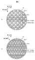
図5は、多孔質セラミックハニカム吸着材の一例を示す流入側の端面図であり、図5(a)及び(b)はそれぞれ、水が流れる方向と直交する方向の流路の断面が四角形の場合の端面図及び水が流れる方向と直交する方向の流路の断面が三角形の場合の端面図である。水が流れる方向とは、多孔質セラミックハニカム吸着材の流入側である入口から出口へ向かう方向を指す。直交する方向とは、水が流れる方向に対して略直角に形成される角度を意味し、90度のみを指すものではない。ここで、端面とは、多孔質セラミックハニカム吸着材22のOリング203との接触面を言い、処理水が流れる方向に対向して、処理前の水が流入する第1の面と、処理後の水が流出する第2の面とがある。なお、図5(a)には、断面が正方形の流路を示し、図5(b)には、断面が正三角形の流路を示しているが、これに限定されるものではない。例えば長方形又は二等辺三角形などであってもよい。
FIG. 5 is an end view on the inflow side showing an example of the porous ceramic honeycomb adsorbent, and FIGS. 5 (a) and 5 (b) each have a quadrangular cross section in the direction perpendicular to the direction in which water flows. It is an end view in the case where the cross section of the flow path in the direction orthogonal to the end view and the direction in which water flows is a triangle. The direction in which water flows refers to the direction from the inlet to the outlet on the inflow side of the porous ceramic honeycomb adsorbent. The orthogonal direction means an angle formed substantially perpendicular to the direction in which water flows, and does not indicate only 90 degrees. Here, the end surface refers to a contact surface with the O-
図5(a)及び(b)に示すように、多孔質セラミックハニカム吸着材22は、外周壁209と、外周壁209の内側に設けられた複数の流路212と、隣り合う流路212の間を隔てる隔壁210とを有している。
5A and 5B, the porous
複数の流路212は、端面において互いに平行でない第1方向及び第2方向に並んで配置されており、流入側の面から流出側の面まで貫通している貫通孔を、流入側の端面又は流出側の端面を目封止することにより形成されている。具体的には、処理前の水の流入側が開口し、反対側の処理後の水の流出側が目封止部211によって目封止された第1の流路212aと、処理後の水の流出側が開口し、反対側の処理前の水の流入側が目封止部211によって目封止された第2の流路212bとを有する。第1の流路212aと第2の流路212bとは、第1方向及び第2方向にそれぞれ交互に配置されている。流路212の断面部の一辺の長さは、例えば0.5〜5mm程度である。
The plurality of
また、隔壁210に形成される連通孔は、流路212の径よりも細い孔構造である平均細孔径(例えば20μm程度)で構成され、隣り合う流路212間(例えば第1の流路212aと第2の流路212bとの間)を連通する多数の連通孔(図示は省略)が形成されている。
The communication hole formed in the
図6は、多孔質セラミックハニカム吸着材の、水が流れる方向に沿う断面図である。図6に示すように、多孔質セラミックハニカム吸着材22には、流入側が開口した第1の流路212aに処理前の水が流入する。第1の流路212aに流入した処理前の水は、隔壁210に形成された多数の連通孔を通じて、第1の流路212aと隣り合う第2の流路212bに流れる。隔壁210の表面又は隔壁210に形成された連通孔の内面を水が通過するときに、水に含まれる有機物を吸着し、除去する。この後、第2の流路212bに流れ込んだ水は、第2の流路212bの開口した流出側から流出する。
FIG. 6 is a cross-sectional view of the porous ceramic honeycomb adsorbent along the direction of water flow. As shown in FIG. 6, the pre-treatment water flows into the porous
多孔質セラミックハニカム吸着材22は、上記した構造を有することで、吸着材に保持されている水が排出されやすく、その両端に設置された圧力開放バルブVL6、調節バルブVL7の開閉動作により、内部に保持された水を効率的に排出することができる。
Since the porous
次に、多孔質セラミックハニカム吸着材の機能について説明する。
例えば海水淡水化処理においては、海水中に溶存する有機物のうち、RO膜に選択的に吸着するのは、主に多糖類であり、多糖類のうち酸性多糖類は負に帯電しており、また糖類は水溶性の物質で、水酸基を数多く有している。
Next, the function of the porous ceramic honeycomb adsorbent will be described.
For example, in seawater desalination treatment, among organic substances dissolved in seawater, it is mainly polysaccharides that are selectively adsorbed to the RO membrane, and acidic polysaccharides among the polysaccharides are negatively charged, Saccharides are water-soluble substances and have many hydroxyl groups.
一方、アルミナのような金属酸化物の水溶液中での表面は、水溶液のpHがその等電点より低い場合には正に帯電し、逆に水溶液のpHがその等電点より高い場合には負に帯電する。例えばアルミナの等電点は、通常pH=9付近にあるため、中性水溶液中でのアルミナ表面は正に帯電し、pH=10のアルカリ性水溶液中でのアルミナ表面は負に帯電している。また、アルミナ等の金属酸化物上には酸素原子が多く存在しており、これらの酸素原子は、水溶性物質が有する水酸基と水素結合を形成する。このため、金属酸化物上には、水溶性の物質が吸着する。 On the other hand, the surface of an aqueous solution of a metal oxide such as alumina is positively charged when the pH of the aqueous solution is lower than its isoelectric point, and conversely when the pH of the aqueous solution is higher than its isoelectric point. Negatively charged. For example, since the isoelectric point of alumina is usually around pH = 9, the alumina surface in a neutral aqueous solution is positively charged, and the alumina surface in an alkaline aqueous solution at pH = 10 is negatively charged. Moreover, many oxygen atoms exist on metal oxides, such as an alumina, and these oxygen atoms form a hydrogen bond with the hydroxyl group which a water-soluble substance has. For this reason, a water-soluble substance is adsorbed on the metal oxide.
このため、セラミックフィルタの溶液導入側の表面を金属酸化物でコーティングすることで、一層有機物の補足性能を向上できる。なお、金属酸化物は、元は金属由来であるが、既に酸化が完了している物質であるため、オゾンガスに対して耐性を持つものである。 For this reason, the supplementary performance of organic matter can be further improved by coating the surface of the ceramic filter on the solution introduction side with a metal oxide. Note that the metal oxide is originally derived from a metal but has already been oxidized, and thus has resistance to ozone gas.
(実験例1)
多孔質セラミックハニカム吸着材の最適な表面材質を検討するために、次の検討を行った。すなわち、多孔質セラミックハニカム吸着材の表面材質となり得る金属酸化物の粉末を用いて、海水中に含まれる天然有機物の一例としてヒアルロン酸の吸着量を比較した。
(Experimental example 1)
In order to investigate the optimum surface material of the porous ceramic honeycomb adsorbent, the following investigation was conducted. That is, the amount of hyaluronic acid adsorbed as an example of a natural organic substance contained in seawater was compared using a metal oxide powder that can be a surface material of a porous ceramic honeycomb adsorbent.
金属酸化物の例として5種類を用いた。コーディエライト、α−アルミナ、γ−アルミナ、酸化チタン、酸化亜鉛にてそれぞれサンプルを作成し測定した結果、表面材質の表面積当たりのヒアルロン酸吸着量はα−アルミナがコーディエライトの約10倍、酸化チタンおよび酸化亜鉛の約3倍で突出して大きかった。また、γ−アルミナもα−アルミナと同様の結果が得られた。 Five types of metal oxides were used. As a result of preparing and measuring samples with cordierite, α-alumina, γ-alumina, titanium oxide, and zinc oxide, the amount of hyaluronic acid adsorbed per surface area of the surface material was about 10 times that of cordierite. It was about 3 times larger than that of titanium oxide and zinc oxide. Further, γ-alumina gave the same results as α-alumina.
以上の点から、隔壁の少なくとも表面がアルミナで形成された多孔質セラミックハニカム吸着材は、RO膜に吸着しやすい物質、すなわち多糖類を、原水から除去するのに好適である。すなわち、多孔質セラミックハニカム吸着材22は、吸着部としての隔壁210がセラミックからなるものであればよいが、さらに隔壁210の少なくとも表面がアルミナで形成されていることが好ましい。多孔質セラミックハニカム吸着材22の隔壁210は、例えばアルミナ以外の例えばコーディエライト等のセラミック上に、アルミナが形成されたものであってもよく、隔壁210の全体がアルミナで形成されたものであってもよい。このとき、アルミナは、α−アルミナであっても、γ−アルミナであっても良い。
In view of the above, the porous ceramic honeycomb adsorbent in which at least the surfaces of the partition walls are made of alumina is suitable for removing substances that are easily adsorbed on the RO membrane, that is, polysaccharides, from raw water. In other words, the porous
以上の結果を元に、本実施例では、表面がアルミナであるセラミックを吸着材に用いた。むろん、表面がアルミナ以外である場合を排除するものではない。 Based on the above results, in this example, ceramic whose surface is alumina was used as the adsorbent. Of course, the case where the surface is other than alumina is not excluded.
(実験例2)
多孔質セラミックハニカム吸着材による海水に含まれる有機物(以下、天然有機物と記載する)の吸着除去について、具体的な実験結果を説明する。
(Experimental example 2)
Specific experimental results will be described for the adsorption removal of organic substances (hereinafter referred to as natural organic substances) contained in seawater by the porous ceramic honeycomb adsorbent.
発明者らの検討の結果、隔壁210の表面がアルミナでコーティングされた多孔質セラミックハニカム吸着材22は、海水中の天然有機物を捕捉する特性を有することが確認された。具体的には、多孔質セラミックハニカム吸着材22は、コーディエライトからなる隔壁210の上に、アルミナ(γ−アルミナ)をコーティングしたものを用いた。アルミナを含むスラリーを、多孔質セラミックハニカム吸着材内部に吸引して供給した後、乾燥して焼成した。アルミナのコーティング量から換算したアルミナの厚みは1μm以下である。
As a result of the examination by the inventors, it was confirmed that the porous
さらに、多孔質セラミックハニカム吸着材22として、その隔壁210の表面材質をセラミックの一種であるコーディエライトとした場合と、隔壁210の表面材質をアルミナとした場合における、海水に含まれる有機物の捕捉性能を比較した。例えば横浜港で採取した海水を、空間速度120(1/h)で多孔質セラミックハニカム吸着材22に通水したところ、表面材質がコーディエライトである場合には、海水中に含まれる天然有機物の除去率が3〜7%であったのに対し、表面材質がアルミナである場合には、海水中に含まれる天然有機物の除去率が10〜60%であった。すなわち、海水中の天然有機物を捕捉するためには、隔壁210の表面材質がアルミナである多孔質セラミックハニカム吸着材がより好適であることが確認された。
Further, as the porous
(実験例3)
次に、多孔質セラミックハニカム吸着材に対する天然有機物の吸着及び除去の評価を行った。以下に、その実験方法について説明する。
(Experimental example 3)
Next, evaluation of adsorption and removal of natural organic substances on the porous ceramic honeycomb adsorbent was performed. The experimental method will be described below.
まず、多孔質セラミックハニカム吸着材を準備した。多孔質セラミックハニカム吸着材の平均細孔径は、特に限定されるものではないが、一般に平均細孔径が小さいほど単位体積あたりの表面積(比表面積)が大きくなり、吸着容量が大きくなることから、小さい平均細孔径ほど望ましい。一方、ハーゲンポアズイユの式より、平均細孔径が小さいほど透過抵抗が大きくなるため、多孔質セラミックハニカム吸着材に水を通過させるのに動力を要することになる。また、平均細孔径が小さいほど微細な懸濁成分により閉塞が起こりやすくなる。そのため、多孔質セラミックハニカム吸着材に最適な平均細孔径は、1μmから50μm程度である。 First, a porous ceramic honeycomb adsorbent was prepared. The average pore diameter of the porous ceramic honeycomb adsorbent is not particularly limited. Generally, the smaller the average pore diameter, the larger the surface area (specific surface area) per unit volume, and the smaller the adsorption capacity. The average pore diameter is desirable. On the other hand, according to the Hagen-Poiseuille equation, the smaller the average pore diameter, the greater the permeation resistance. Therefore, power is required to pass water through the porous ceramic honeycomb adsorbent. In addition, the smaller the average pore diameter, the more likely the blockage occurs due to fine suspended components. Therefore, the optimum average pore diameter for the porous ceramic honeycomb adsorbent is about 1 μm to 50 μm.
なお、本発明における平均細孔径とは、細孔径分布において全細孔容積の50%に相当する細孔直径である。
隔壁の平均細孔径は、例えば水銀圧入式ポロシメータを用いて測定可能である。水銀圧入式ポロシメータは、真空状態にした隔壁試料中に水銀を圧入し、圧入圧力と隔壁試料の細孔内に圧入された水銀の容積との関係を求めることにより、細孔径と細孔容積の関係(細孔径分布)を求める方法である。
In addition, the average pore diameter in the present invention is a pore diameter corresponding to 50% of the total pore volume in the pore diameter distribution.
The average pore diameter of the partition walls can be measured using, for example, a mercury intrusion porosimeter. Mercury intrusion porosimeters inject mercury into a vacuum septum sample and determine the relationship between the indentation pressure and the volume of mercury injected into the pores of the septum sample. This is a method for obtaining the relationship (pore size distribution).
本発明者らは、多孔質セラミックハニカム吸着材として、隔壁210の厚さが0.3mmで平均細孔径が20μmのもの、隔壁210の厚さが1mmで平均細孔径が10μmのもの等を主に使用して、海水を通過させる検討を行った。 The present inventors mainly used a porous ceramic honeycomb adsorbent having a partition wall thickness of 0.3 mm and an average pore diameter of 20 μm, a partition wall thickness of 1 mm and an average pore diameter of 10 μm, and the like. It was used to test the passage of seawater.
具体的には、上記の多孔質セラミックハニカム吸着材に空間速度120(1/h)で海水を通過させて、そのときに発生する差圧を測定したところ、いずれの多孔質セラミックハニカム吸着材においても差圧は最大で4kPaであり、通常の送水ポンプの能力と比べて十分小さいことが確認された。すなわち、隔壁210の厚さが50μm以上あれば、圧力による破壊が免れることを確認した。
Specifically, when the seawater was passed through the porous ceramic honeycomb adsorbent at a space velocity of 120 (1 / h) and the differential pressure generated at that time was measured, in any porous ceramic honeycomb adsorbent, The maximum differential pressure was 4 kPa, which was confirmed to be sufficiently small compared to the capacity of a normal water pump. That is, it was confirmed that if the thickness of the
また隔壁210の厚さは、厚いほど処理対象の溶液が壁内部を通過する時間が増加し、さらに、比表面積が増大するため、吸着性能向上のために好ましい。しかし、壁厚が大きすぎると、吸着面積が減少し、吸着性能が低下してしまう。それらを勘案した上で、適切な設計を行うことになる。
In addition, the thicker the
また、平均細孔径が1μm以上であれば、多孔質セラミックハニカム吸着材として好適である。 An average pore diameter of 1 μm or more is suitable as a porous ceramic honeycomb adsorbent.
(実験例4)
続いて、吸着物の処理実験用に、実験用の処理対象溶液として、海水に含まれる代表的な天然有機物を含む水溶液を用意した。代表的な天然有機物として、RO膜に吸着しやすく、有機ファウリング及びバイオファウリングの原因と考えられているマンナン(多糖の1種。単糖マンノースがグリコシド結合により多数重合した物質。)の水溶液を以下の検討において用いた。マンナンの濃度は、6mg/Lとした。このとき、マンナンを溶解する水溶液として、人工海水を用いた。人工海水には、通常の海水中に含まれるNaCl他、平均的な電解質を含まれるが、天然海水と異なり、天然有機物は含まれない。人工海水は、NaClの濃度が3.5%となるように調製した。
(Experimental example 4)
Subsequently, an aqueous solution containing a typical natural organic substance contained in seawater was prepared as an experimental treatment target solution for the treatment of adsorbate. As a typical natural organic substance, an aqueous solution of mannan (a kind of polysaccharide, a substance in which monosaccharide mannose is polymerized by glycosidic bonds), which is easily adsorbed on RO membranes and is considered to cause organic fouling and biofouling. Was used in the following study. The concentration of mannan was 6 mg / L. At this time, artificial seawater was used as an aqueous solution for dissolving mannan. Artificial seawater contains NaCl and other average electrolytes contained in normal seawater, but unlike natural seawater, it does not contain natural organic matter. Artificial seawater was prepared so that the concentration of NaCl was 3.5%.
マンナン溶液中のマンナンの除去率は、多孔質セラミックハニカム吸着材にマンナン溶液を一定時間通水させたときの通水前後のマンナン溶液のTOC値(Total Organic Carbon:全有機炭素量[mg/L])を全有機炭素計を用いて測定し、溶液中のマンナンの除去率は、次の(式1)で算出した。 The removal rate of mannan in the mannan solution is determined by the TOC value of the mannan solution before and after water passage when the mannan solution is passed through the porous ceramic honeycomb adsorbent for a certain time (Total Organic Carbon: Total organic carbon amount [mg / L ]) Was measured using a total organic carbon meter, and the removal rate of mannan in the solution was calculated by the following (formula 1).
除去率=(吸着材通過前の溶液のTOC値−通過後の溶液のTOC値)/通過前の溶液のTOC値 (式1)
但し、多孔質セラミックハニカム吸着材を用いての評価は手間がかかる為、より簡便な手法で評価できれば、より適切な設計評価が可能となる。そこで、本実験では、QCM法により測定を行った。
発明者らは、後述するが、QCM法によっても、再現性の高い測定が可能であることを見出しており、その対応関係は後述する。
Removal rate = (TOC value of the solution before passing through the adsorbent-TOC value of the solution after passing) / TOC value of the solution before passing (Formula 1)
However, since the evaluation using the porous ceramic honeycomb adsorbent takes time, more appropriate design evaluation can be performed if it can be evaluated by a simpler method. Therefore, in this experiment, measurement was performed by the QCM method.
As will be described later, the inventors have found that measurement with high reproducibility is possible even by the QCM method, and the corresponding relationship will be described later.
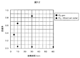
本実験では、洗浄方式と吸着物の洗浄性能の関係を検討した。実験結果を図11に示す。
ここで、回復率の定義を示す。回復率とは、洗浄前後のマンナン吸着量の比B/Aであり、Aは洗浄前の吸着量、Bは洗浄後の吸着量とする。このとき、B/Aを洗浄による吸着性能の回復率(回復率=1を全回復とする)と定義する。すなわち、回復率が高いほど、洗浄性能が高い。QCM法の測定サンプル表面にマンナンを十二分に付着させた後、6種類の洗浄方式で、測定サンプルを洗浄した。その洗浄方式毎の、吸着物の洗浄による回復率を示している。
In this experiment, the relationship between the cleaning method and the cleaning performance of the adsorbate was examined. The experimental results are shown in FIG.
Here, the definition of the recovery rate is shown. The recovery rate is the ratio B / A of the mannan adsorption amount before and after cleaning, where A is the adsorption amount before cleaning and B is the adsorption amount after cleaning. At this time, B / A is defined as a recovery rate of the adsorption performance by washing (recovery rate = 1 is total recovery). That is, the higher the recovery rate, the higher the cleaning performance. After sufficient mannan was adhered to the surface of the measurement sample of the QCM method, the measurement sample was washed by six types of washing methods. The recovery rate by cleaning the adsorbate is shown for each cleaning method.
図11中の1は、オゾンガス10分間で洗浄結果、2はオゾン溶解水(希薄酢酸中)での洗浄結果、3はリファレンスとしての希薄酢酸での洗浄結果、4は過硫酸ナトリウム(Na2S2O8)水溶液で洗浄結果、5は過酸化水素水での洗浄結果、6は水酸化ナトリウム(NaOH)をpH=13の強アルカリ溶液として用いた水溶液での洗浄結果である。なお、市販の界面活性剤による洗浄実験も行ったが、リファレンスに比し特に優位な洗浄効果は得られなかったため、記載は省略している。 In FIG. 11, 1 is the result of cleaning with ozone gas for 10 minutes, 2 is the result of cleaning with ozone-dissolved water (in dilute acetic acid), 3 is the result of cleaning with dilute acetic acid as a reference, and 4 is sodium persulfate (Na 2 S). The result of washing with a 2 O 8 ) aqueous solution, 5 the result of washing with aqueous hydrogen peroxide, and 6 the result of washing with an aqueous solution using sodium hydroxide (NaOH) as a strong alkali solution with pH = 13. In addition, although a cleaning experiment using a commercially available surfactant was also performed, the cleaning effect superior to that of the reference was not obtained, so the description is omitted.
図11から分かるように、気体状態でのオゾンガスによる洗浄能力が、他の洗浄方式に比べ、圧倒的な回復率を達成できることが明らかとなった。また同時に、オゾン溶解水による洗浄効果は、限定されたものであることも明らかとなった。 As can be seen from FIG. 11, it became clear that the cleaning ability with ozone gas in a gaseous state can achieve an overwhelming recovery rate compared to other cleaning methods. At the same time, it became clear that the cleaning effect of ozone-dissolved water was limited.
図12は、オゾンガスと、オゾン洗浄水での洗浄能力を、時間経過と共に評価したものである。黒丸のオゾンガスによる回復率は時間と共に上昇している。一方、黒四角のオゾン洗浄水による回復率は、時間が経過しても向上が見られない。処理時間30分の時点で比較すると、オゾンガスによる回復率は、オゾン洗浄水による回復率の20倍以上に達し、時間経過と共にさらにその差は開いて行くものと考えられる。 FIG. 12 shows the evaluation of cleaning ability with ozone gas and ozone cleaning water over time. The recovery rate of black circles with ozone gas increases with time. On the other hand, the recovery rate by the black square ozone cleaning water does not improve even if time passes. When compared at the time of the treatment time of 30 minutes, the recovery rate by the ozone gas reaches 20 times or more the recovery rate by the ozone cleaning water, and the difference is considered to further increase with time.
このように、発明者らの実験によって、気体状態のオゾンガスによる吸着材の洗浄が、圧倒的な性能を有することが明らかとなった。 As described above, the experiments by the inventors have revealed that cleaning of the adsorbent with gaseous ozone gas has overwhelming performance.
<実験の詳細>
再現実験用の、詳細な実験手法を以下に説明する。
洗浄方法は、洗浄の考え方により、以下の3つに分類される。すなわち、(1)高酸化力を有する洗浄成分で吸着物を酸化、分解する方法、(2)アルミナ表層を溶解する方法、(3)界面活性剤の浸透作用を利用して表層吸着物を剥離する方法、である。
<Details of experiment>
A detailed experimental method for the reproduction experiment is described below.
The cleaning methods are classified into the following three types according to the concept of cleaning. That is, (1) a method of oxidizing and decomposing an adsorbate with a cleaning component having a high oxidizing power, (2) a method of dissolving an alumina surface layer, and (3) peeling off a surface layer adsorbent using the permeation action of a surfactant. How to do.
(1)高酸化力を有する洗浄成分で吸着物を酸化・分解する方法
この分類では、過酸化水素水(H2O2)、過硫酸ナトリウム(Na2S2O8)水溶液、オゾン溶解水(O3−dissolved water、オゾン溶解濃度:0.2〜0.4mmol/L、10mmol/Lの希薄酢酸中)及びオゾンガス(O3 gas、オゾンガス濃度:2.1 mmol/L)を用いた。
(1) Method to oxidize and decompose adsorbate with cleaning component having high oxidizing power
In this classification, hydrogen peroxide solution (H 2 O 2 ), sodium persulfate (Na 2 S 2 O 8 ) aqueous solution, ozone-dissolved water (O 3 -dissolved water, ozone dissolution concentration: 0.2 to 0.4 mmol / L, in 10 mmol / L dilute acetic acid) and ozone gas (O 3 gas, ozone gas concentration: 2.1 mmol / L).
過酸化水素水は、過酸化水素濃度が0.5mol/L、pHが約8〜9となるように、過酸化水素水(濃度30%)と、水酸化ナトリウム(NaOH)水溶液(濃度1mmol/L、pH=11)を用いて調製した。調整後の過酸化水素水のpHは、pH=8.6であった。また、過硫酸ナトリウム水溶液は、過硫酸ナトリウム濃度が0.5mol/L、pHが約2〜3となるように、過硫酸ナトリウムと、水酸化ナトリウム(NaOH)水溶液(濃度1mmol/L、pH=11)を用いて調製した。調整後の過硫酸ナトリウム水溶液のpHは、pH=2.1であった。
The hydrogen peroxide solution includes a hydrogen peroxide solution (
オゾン溶解水調製の際は、水中におけるオゾンの分解速度はpH値が大きいほど(アルカリ側)速いことを考慮し、オゾンの液相中での分解を抑制するために、pH=3程度の希薄酢酸(10mmol/Lの酢酸(AcOH)水溶液)にオゾンガスを約2時間導入した。また、オゾンガス及びオゾン溶解水作製には、市販の電解式オゾン発生装置を用いた。 In preparing ozone-dissolved water, considering the fact that the decomposition rate of ozone in water is faster as the pH value is larger (alkaline side), a diluted pH of about 3 is used to suppress decomposition of ozone in the liquid phase. Ozone gas was introduced into acetic acid (10 mmol / L acetic acid (AcOH) aqueous solution) for about 2 hours. Moreover, the commercially available electrolytic ozone generator was used for ozone gas and ozone solution water preparation.
上記オゾンガス発生装置を用いたときのオゾンガスを含む空気の流量は、約170mL/minであり、このうちオゾンガスは、オゾンの生成条件から、約9mL/min流れる。 When the ozone gas generator is used, the flow rate of air containing ozone gas is about 170 mL / min, and ozone gas flows about 9 mL / min from the ozone generation conditions.
オゾンガスによる洗浄の実験系を図10に示す。
マンナン吸着後のQCM法のQCMセンサ41をオゾンガスで洗浄する場合、セル42内のサンプル水を予め抜いた上で、QCMセンサ41を図7に示すQCM装置4から外しておく。次いで、オゾン発生装置50からPFAチューブ51を通してオゾンガス52を導入した。PFAチューブ51のオゾンガス52放出口は、PPビーカ53及びさらにその中にあるPFAビーカ54の底まで到達させ、PFAビーカ54内に設置したQCMセンサ41まで導入した。QCMセンサ41は、専用の高腐食性材によるセンサホルダ55で縦向きに保持した。PPビーカ53は、口の上から高耐腐食性シート56で覆い、PPビーカ53及びPFAビーカ54の内部の雰囲気を保持した。この実験系で、所定時間にわたり、オゾンガス52を通気して、QCMセンサ41を洗浄した。
FIG. 10 shows an experimental system for cleaning with ozone gas.
When the
(2)アルミナ表層を溶解する方法
この分類では、QCM法のQCMセンサ表層のアルミナが溶解することにより、表層に吸着していた吸着物が脱落し、除去される。溶解液として、水酸化ナトリウム(NaOH)水溶液(濃度0.1mol/L、pH=13)を用いた。
(2) Method for Dissolving Alumina Surface Layer In this classification, the adsorbate adsorbed on the surface layer falls off and is removed by dissolving the alumina on the surface of the QCM sensor in the QCM method. A sodium hydroxide (NaOH) aqueous solution (concentration 0.1 mol / L, pH = 13) was used as the solution.
(3)界面活性剤の浸透作用を利用して表層吸着物を剥離する方法
この分類は、界面活性剤の作用を用いて洗浄する方法であるが、市販の洗浄材では有意に吸着物質を除去できなかったため、説明を割愛する。
(3) Method of peeling surface layer adsorbate using the permeation action of surfactant
This classification is a method of cleaning using the action of a surfactant, but since the adsorbed substances could not be removed significantly with a commercially available cleaning material, the explanation is omitted.
上記した吸着量Aの評価を行った後に、以上の洗浄処理を終えたQCMセンサ41を用いて、再びマンナンの吸着量Bを評価した。洗浄後のQCMセンサ41は、再びQCM装置に取り付け、洗浄前に行った吸着実験と同様にマンナンによる吸着実験を行った。
After the above-described adsorption amount A was evaluated, the mannan adsorption amount B was evaluated again using the
ここで、洗浄前後のマンナン吸着量の比B/Aを、洗浄によるセンサ上アルミナの吸着性能の回復率(回復率=1を全回復とする)と定義する。すなわち、回復率が高いほど、洗浄性能が高い。上記した各洗浄溶液又は洗浄ガスを用いたときのそれぞれの回復率を評価した洗浄評価結果を図11に示す。 Here, the ratio B / A of the mannan adsorption amount before and after cleaning is defined as the recovery rate of the adsorption performance of alumina on the sensor by the cleaning (recovery rate = 1 is the total recovery). That is, the higher the recovery rate, the higher the cleaning performance. FIG. 11 shows a cleaning evaluation result obtained by evaluating each recovery rate when each of the above-described cleaning solutions or cleaning gases is used.
図11より、溶液による洗浄処理(全て10分処理)、すなわち過酸化水素水、過硫酸ナトリウム水溶液、オゾン溶解水、水酸化ナトリウム水溶液を用いた洗浄処理は、いずれも回復率が0.05〜0.1程度であり、吸着物の洗浄性能は低かった。 From FIG. 11, the cleaning treatment with the solution (all treatment for 10 minutes), that is, the cleaning treatment using the hydrogen peroxide solution, the sodium persulfate aqueous solution, the ozone-dissolved water, and the sodium hydroxide aqueous solution all have a recovery rate of 0.05 to The cleaning performance of the adsorbate was low.
しかし、オゾンガスを通気したときのみ、回復率が0.65と突出して高かった。特に、オゾン溶解水とオゾンガスでは、両方ともオゾンを洗浄成分として用いているにもかかわらず、処理時間が同じ10分で、回復率に約10倍の差があった。 However, the recovery rate was as high as 0.65, only when ozone gas was passed. In particular, in ozone-dissolved water and ozone gas, the treatment time was the same 10 minutes, although the ozone was used as a cleaning component, and there was a difference of about 10 times in the recovery rate.
さらに、吸着処理後の洗浄にオゾン溶解水及びオゾンガスを用いたときの、それぞれの回復率の処理時間依存性を比較した結果を図12に示す。吸着処理後の洗浄にオゾン溶解水及びオゾンガスを用いたときの、それぞれの吸着性能回復率の処理時間依存性を比較したグラフである。 Furthermore, the result of having compared the processing time dependence of each recovery rate when ozone-dissolved water and ozone gas are used for the washing | cleaning after adsorption processing is shown in FIG. It is the graph which compared the processing time dependence of each adsorption performance recovery rate when ozone dissolved water and ozone gas are used for the washing | cleaning after adsorption processing.
図12より、オゾンガスでは、処理時間と共に回復率が上がり、30分間の処理後では、回復率が0.84を示した。一方、オゾン溶解水では、処理時間が30分のとき、60分のときのいずれも、回復率が0.04にとどまり、処理時間に伴う回復率の増加がなく、洗浄効果の向上がみられなかった。なお、グラフには図示しないが、オゾンを溶解していない希薄酢酸単独でも、処理時間60分で回復率が0.04であった。このことから、溶存するオゾンによる洗浄効果がほとんどなかったことが分かる。 From FIG. 12, with ozone gas, the recovery rate increased with the treatment time, and after 30 minutes of treatment, the recovery rate was 0.84. On the other hand, in ozone-dissolved water, the recovery rate is only 0.04 when the treatment time is 30 minutes and 60 minutes, there is no increase in the recovery rate with the treatment time, and the cleaning effect is improved. There wasn't. Although not shown in the graph, even with dilute acetic acid alone in which ozone was not dissolved, the recovery rate was 0.04 after a treatment time of 60 minutes. From this, it can be seen that there was almost no cleaning effect due to dissolved ozone.
オゾンガスによるマンナン除去のメカニズムは、以下のように考えられる。すなわち、QCMセンサ41上のアルミナに吸着した吸着物質(本実験例ではマンナン)は、オゾンガスにより分解され、気相に拡散したと考えられる。また、別のメカニズムとしては、吸着物質がオゾンガスと接触することで水に溶解しやすい物質となり、再びセル42内(図7参照。)を処理水で満たしてQCMセンサ41表面に処理水を接触させたときに、液相に溶解したと考えられる。
The mechanism of mannan removal by ozone gas is considered as follows. That is, it is considered that the adsorbed substance (mannan in this experimental example) adsorbed on alumina on the
次に、オゾン溶解水とオゾンガスとの回復率の差は、何に起因するのかを以下に考察する。
一般に、オゾン発生装置から、オゾン水生成装置やインジェクタ(エジェクタやエゼクタともいう。液の流路の一部に隘路を設け、その部分の流速を速くすることにより、減圧状態としてオゾンガスを引き込むための器具)を通してオゾンガスを水(中性)に溶解させる場合でも、水中に溶解するオゾンガスは、オゾン発生装置からのオゾン発生量の5%程度であり、残りのオゾンガスは、ほとんど大気中に放散すると言われている。本実施例で用いたオゾン発生装置によるオゾン発生量は、最大200g/m3(約4.2mmol/L)であるため、その5%程度、すなわち約10g/m3(約0.2mmol/L)のオゾンガスが、水に溶解したと考えられる。なお、実施例で述べたように、酸性側ではオゾンの溶解量は増加する。
Next, what causes the difference in recovery rate between ozone-dissolved water and ozone gas will be discussed below.
In general, an ozone water generator or an injector (also called an ejector or ejector) is provided with a bottleneck in part of the liquid flow path, and the flow rate of that part is increased to draw ozone gas in a reduced pressure state from the ozone generator. Even if ozone gas is dissolved in water (neutral) through a device), ozone gas dissolved in water is about 5% of the amount of ozone generated from the ozone generator, and the remaining ozone gas is said to be almost diffused into the atmosphere. It has been broken. Since the maximum amount of ozone generated by the ozone generator used in this example is 200 g / m 3 (about 4.2 mmol / L), about 5% thereof, that is, about 10 g / m 3 (about 0.2 mmol / L). ) Ozone gas is considered dissolved in water. As described in the examples, the amount of ozone dissolved increases on the acidic side.
すなわち、同一のオゾン発生装置を用いた同一出力条件では、オゾン自体の濃度としては、気相中のほうが、液相中よりも、10〜20倍程度高くすることができ、その分吸着物の除去反応が進行すると言える。本実施例において、オゾン溶解水を用いた場合より、オゾンガスを用いた場合の方が、最大で約20倍大きい回復率を示したのは、上記の理由によると考えられる。一方、オゾン溶解水において、オゾン溶解濃度を上げようとすると、その分オゾン発生装置の出力を10〜20倍上げる必要があり、経済的な観点から合理的でない。 That is, under the same output conditions using the same ozone generator, the concentration of ozone itself can be about 10 to 20 times higher in the gas phase than in the liquid phase. It can be said that the removal reaction proceeds. In this example, it is considered that the reason why the ozone gas was used was about 20 times larger at the maximum when the ozone gas was used than when the ozone dissolved water was used. On the other hand, in the ozone-dissolved water, if the ozone-dissolved concentration is to be increased, the output of the ozone generator needs to be increased by 10 to 20 times, which is not rational from an economical viewpoint.
よって、オゾンガスによる有機物処理を行う本発明の優位性は明らかなものである。 Therefore, the superiority of the present invention in which the organic substance treatment with ozone gas is performed is clear.
本実施例では、吸着材としての多孔質セラミックハニカム吸着材の交換の処理手順について述べる。 In this example, a procedure for replacing a porous ceramic honeycomb adsorbent as an adsorbent will be described.
水処理システムは計算部を備えており、この計算部による計算は、吸着モジュールの運用開始時の処理能力と測定時の処理能力とを比較し、運用開始時よりも処理能力が落ちていることを確認又は判定するものである。すなわち吸着モジュールの使用時間を測定するものである。 The water treatment system has a calculation unit, and the calculation by this calculation unit compares the processing capacity at the start of operation of the adsorption module with the processing capacity at the time of measurement, and the processing capacity is lower than at the start of operation. Is confirmed or determined. That is, the usage time of the adsorption module is measured.
吸着モジュールの水処理性能が運用当初よりも落ちている場合に、例えば水処理システムに備えられた表示部に交換を行うように表示される。また、判定結果を水処理システムの管理者又はメンテナンスを行うサービスメーカにメール等で連絡し、吸着モジュールの交換を行うように知らせてもよい。この場合は、水処理システム以外からも吸着モジュールの交換時期(交換を推奨する時期)を知ることができる。 When the water treatment performance of the adsorption module is lower than that at the beginning of operation, for example, it is displayed on the display unit provided in the water treatment system so as to be replaced. In addition, the determination result may be notified to an administrator of the water treatment system or a service maker performing maintenance by e-mail or the like so as to replace the adsorption module. In this case, it is possible to know the replacement time of the adsorption module (time when replacement is recommended) from other than the water treatment system.
吸着モジュールの交換のタイミングは、例えば水処理システムに備わる計算部によって管理されており、適切な交換時期を計算部からユーザに通知してもよい。また、吸着モジュールの交換のタイミングは、例えば多孔質セラミックハニカム吸着材メーカによって管理されており、適切な交換時期を多孔質セラミックハニカム吸着材メーカからユーザに通知してもよい。 The replacement timing of the adsorption module is managed by, for example, a calculation unit provided in the water treatment system, and an appropriate replacement time may be notified to the user from the calculation unit. Further, the replacement timing of the adsorption module is managed by, for example, a porous ceramic honeycomb adsorbent maker, and an appropriate replacement time may be notified from the porous ceramic honeycomb adsorbent maker to the user.
この交換時期の計算では、先に使用した吸着モジュールの運用開始から交換するまでの時間、すなわち使用時間を記憶する。また、現在使用されている吸着モジュールの運用時間を測定し、先に使用した吸着モジュールの交換時期との差を判定し、交換までの推奨時間を計算し、そして、適切な水処理性能が得られる状態の耐用期間の残り時間を通知してもよい。適切な水処理性能は使用する水処理システムによって適宜設定するものである。また、吸着モジュールの交換期間を測定し記憶することにより、その水処理システムに対応する交換頻度を求め、通知してもよい。この場合は、水処理システムで処理する被処理水と吸着モジュールの耐久性能との関係から吸着モジュールそのものの性能低下のみならず被処理水との関係からより適した交換の時期を提案することができる。 In the calculation of the replacement time, the time from the start of operation of the previously used adsorption module to the replacement, that is, the usage time is stored. Also, measure the operation time of the adsorption module currently in use, determine the difference from the replacement time of the adsorption module used earlier, calculate the recommended time until replacement, and obtain appropriate water treatment performance. You may notify the remaining time of the useful life of the state to be prepared. Appropriate water treatment performance is appropriately set depending on the water treatment system used. Moreover, you may obtain | require and notify the replacement frequency corresponding to the water treatment system by measuring and memorize | storing the replacement | exchange period of an adsorption | suction module. In this case, it is possible to propose a more suitable replacement time based not only on the performance deterioration of the adsorption module itself but also on the relationship with the treated water from the relationship between the treated water to be treated by the water treatment system and the durability performance of the adsorption module. it can.
これらの通知方法は、その他、先に述べたユーザ、システム管理者又はメールによる通知方法を用いてもよい。この場合は、吸着モジュールの処理能力が低下する前に事前に交換時期を知らせることができる。そのため、他の構成のメンテナンスと併せて水処理システム全体のメンテナンス計画を立てることに役立てられる。 In addition to these notification methods, the above-described notification method by the user, the system administrator, or mail may be used. In this case, the replacement time can be notified in advance before the processing capacity of the adsorption module decreases. Therefore, it is useful for making a maintenance plan for the entire water treatment system together with maintenance of other configurations.
また、通知方法は複数備えてもよく、例えば水処理システムの管理者等に知らせるだけでなく、吸着モジュールを販売又は供給するメーカに併せて知らせることで、吸着モジュールの交換時期をそれぞれに事前に知らせることができる。この場合は、水処理システムのユーザが、処理能力が低下した吸着モジュールの交換を望む際に前記メーカは既に水処理システムに対応する交換用の吸着モジュールを事前に準備することができる。 In addition, a plurality of notification methods may be provided. For example, not only the manager of the water treatment system, but also the manufacturer who sells or supplies the adsorption module is notified in advance of the replacement time of the adsorption module. I can inform you. In this case, when the user of the water treatment system desires to replace the adsorption module having a reduced processing capacity, the manufacturer can already prepare an adsorption module for replacement corresponding to the water treatment system in advance.
これらの通知方法は他の実施例でも同様に適用可能であり、水処理システムの効率的な運用を考慮すると実施することが望ましい。
なお、これらの通知方法は必須構成ではなく、水処理システムの実施形態の一例である。
These notification methods can be similarly applied to other embodiments, and it is desirable to implement them in consideration of efficient operation of the water treatment system.
In addition, these notification methods are not essential components, but are an example of an embodiment of a water treatment system.
また、先に述べた通知においては、吸着モジュールの交換だけでなく、洗浄によって吸着モジュールの性能を回復させる場合には、洗浄頻度として洗浄する時期(洗浄を推奨する時期)を通知してもよい。この場合は、吸着モジュールを洗浄することによって長時間利用することを実現できる。 Further, in the notification described above, when the performance of the adsorption module is recovered not only by replacement of the adsorption module but also by cleaning, the cleaning time (time when cleaning is recommended) may be notified. . In this case, it can be used for a long time by washing the adsorption module.
また、洗浄頻度と交換頻度とを併せて通知してもよく、この場合は、洗浄による吸着モジュールの長寿命化、交換時期の適切な提案、及びメンテナンス計画の立案に貢献できる。他にも、全体として水処理システムの水処理性能の低減を防止することができる。 Further, the cleaning frequency and the replacement frequency may be notified together, and in this case, it is possible to contribute to the extension of the life of the adsorption module by the cleaning, the appropriate proposal of the replacement time, and the preparation of the maintenance plan. In addition, it is possible to prevent a reduction in water treatment performance of the water treatment system as a whole.
さらに、測定された各情報を参考として統計的又は経験的に洗浄頻度と交換頻度を求めることもできる。 Further, the cleaning frequency and the replacement frequency can be obtained statistically or empirically with reference to each measured information.
前記図4に示す吸着モジュールMは、必要に応じて並列及び直列に配列することができ、各吸着モジュールMの入口及び出口には通水用のバルブが設けてある(図示は省略)。さらに、各吸着モジュールMの入口又は出口には、圧力開放バルブVL6及び排水量を調節する調節バルブVL7が設けてある(図示は省略)。吸着モジュールMの交換の際には、交換する吸着モジュールMの入口及び出口の通水用のバルブを閉状態とした後、圧力開放バルブVL6及び排水量を調節する調節バルブVL7を開放してハウジング201の圧力を開放し、中の処理水を排出することで、ハウジング201から多孔質セラミックハニカム吸着材22を取り出すことが可能になる。この後、新しい多孔質セラミックハニカム吸着材22をハウジング201に装填し、ハウジング201を組み立て、吸着モジュールMの圧力開放バルブVL6及び排水量を調節する調節バルブVL7を閉じたのち、吸着モジュールMの出口側バルブ及び入口側通水用のバルブを開けて通水を開始する。
The adsorption modules M shown in FIG. 4 can be arranged in parallel and in series as necessary, and valves for water passage are provided at the inlet and outlet of each adsorption module M (not shown). Furthermore, a pressure release valve VL6 and an adjustment valve VL7 for adjusting the amount of drainage are provided at the inlet or outlet of each adsorption module M (not shown). When replacing the adsorption module M, the inlet and outlet valves for the adsorption module M to be replaced are closed, and then the pressure release valve VL6 and the adjustment valve VL7 for adjusting the amount of drainage are opened to open the
このように、本実施例による多孔質セラミックハニカム吸着材は、適切な洗浄処理及び交換処理を施すことによって、長期間にわたって透過性能を維持することが可能である。 Thus, the porous ceramic honeycomb adsorbent according to the present example can maintain the permeation performance over a long period of time by performing an appropriate cleaning process and replacement process.
なお、前述したオゾンガス処理により吸着した天然有機物を除去した後、すぐに多孔質セラミックハニカム吸着材を海水淡水化処理に使用することも可能である。 It is also possible to use the porous ceramic honeycomb adsorbent for seawater desalination immediately after removing the natural organic matter adsorbed by the ozone gas treatment described above.
本実施形態によれば、前処理部において、RO膜の性能を劣化させる原因となる有機物をあらかじめ多孔質セラミックハニカム吸着材によって選択的に原水から除去することができ、さらに、多孔質セラミックハニカム吸着材に吸着した有機物を、オゾンガスを用いた洗浄処理により効率的に除去して、多孔質セラミックハニカム吸着材を再生することができる。これにより、RO膜モジュールの交換頻度及び多孔質セラミックハニカム吸着材の交換頻度が減少し、海水淡水化システムのランニングコストを低減することができる。このため、水処理システムの水処理コストを低減することができる。 According to the present embodiment, in the pretreatment section, organic substances that cause deterioration of the performance of the RO membrane can be selectively removed from the raw water in advance by the porous ceramic honeycomb adsorbent, and further, the porous ceramic honeycomb adsorption The organic substance adsorbed on the material can be efficiently removed by a cleaning process using ozone gas, and the porous ceramic honeycomb adsorbent can be regenerated. Thereby, the replacement frequency of the RO membrane module and the replacement frequency of the porous ceramic honeycomb adsorbent are reduced, and the running cost of the seawater desalination system can be reduced. For this reason, the water treatment cost of a water treatment system can be reduced.
以上、本発明者によってなされた発明を実施の形態に基づき具体的に説明したが、本発明は前記実施の形態に限定されるものではなく、その要旨を逸脱しない範囲で種々変更可能であることはいうまでもない。 As mentioned above, the invention made by the present inventor has been specifically described based on the embodiment. However, the present invention is not limited to the embodiment, and various modifications can be made without departing from the scope of the invention. Needless to say.
以上の実施の形態において、便宜上その必要があるときは、複数のセクションまたは実施の形態に分割して説明したが、特に明示した場合を除き、それらはお互いに無関係なものではなく、一方は他方の一部又は全部の変形例、詳細、補足説明等の関係にある。また、以上の実施の形態において、要素の数等(個数、数値、量、範囲等を含む)に言及した場合、特に明示した場合及び原理的に明らかに特定の数に限定される場合等を除き、その特定の数に限定されるものではなく、特定の数以上でも以下でも良い。 In the above embodiment, when it is necessary for the sake of convenience, the description has been divided into a plurality of sections or embodiments. However, unless otherwise specified, they are not irrelevant to each other, and one is the other. There are some or all of the modifications, details, supplementary explanations, and the like. Further, in the above embodiment, when the number of elements (including the number, numerical value, quantity, range, etc.) is mentioned, particularly when clearly indicated and when it is clearly limited to a specific number in principle, etc. Except, it is not limited to the specific number, and may be more or less than the specific number.
また上記実験例の中で判明した知見は、それが有意に優位である限りにおいて、本発明の範疇に含むものであり、各実施例と組み合わせられるものである。 In addition, the findings found in the above experimental examples are included in the scope of the present invention as long as they are significantly superior, and are combined with the respective examples.
(検証実験例)
本項では、再現実験のため、QCM法により洗浄性能が評価できることを説明する。QCM法では、水晶振動子の表面に、分子が付着して振動するとその重量変化に比例して共振周波数が変化する現象を利用して、水晶振動子上に形成されたセンサ(以下センサと略記する)上の付着物の微小重量を測定する。
(Example of verification experiment)
This section explains that the cleaning performance can be evaluated by the QCM method for a reproduction experiment. In the QCM method, a sensor (hereinafter abbreviated as a sensor) formed on a crystal resonator is utilized by utilizing a phenomenon in which the resonance frequency changes in proportion to the weight change when molecules adhere to the surface of the crystal resonator and vibrate. Measure the minute weight of the top deposit.
QCM法は、これまで半導体製造などの分野において、真空成膜装置の膜厚測定に用いられてきた。一方、液中では振動子の発振が難しいため、QCM法による測定は真空中や空気中での使用に限定されてきたが、2000年頃から液体中での測定が可能な装置が市販され、医療、バイオサイエンス、材料開発などの分野で活用されるようになってきた。 The QCM method has been used to measure the film thickness of a vacuum film forming apparatus in the field of semiconductor manufacturing and the like. On the other hand, since it is difficult to oscillate the vibrator in liquid, the measurement by the QCM method has been limited to use in vacuum or in air. It has come to be used in fields such as bioscience and material development.
以下に示す吸着性能及び除去性能の評価においても、液体中の微小質量変化が測定可能な市販のQCM装置を用いており、この装置を用いて本事前検討を行った。本事前検討では、上記センサの表面に、多孔質セラミックハニカム吸着材表面と同等のアルミナを形成し、このアルミナを吸着面とした。以下、まずQCM法の測定原理及びQCM装置概要を説明した後に、QCM法で簡便に多孔質セラミックハニカム吸着材での吸着現象を再現できることを記載する。 In the following evaluation of adsorption performance and removal performance, a commercially available QCM apparatus capable of measuring a minute mass change in a liquid was used, and this preliminary examination was performed using this apparatus. In this preliminary study, alumina equivalent to the surface of the porous ceramic honeycomb adsorbent was formed on the surface of the sensor, and this alumina was used as the adsorption surface. Hereinafter, after first explaining the measurement principle of the QCM method and the outline of the QCM apparatus, it will be described that the adsorption phenomenon in the porous ceramic honeycomb adsorbent can be easily reproduced by the QCM method.
まず、QCM装置の測定原理及び装置概要を記載する。QCM法では、水晶振動子に歪み振動を与え、そのときの共振周波数(f)を測定する。この共振周波数(f)は、以下の(式2)に示すSauerbrey式に従い、センサ表面への吸着によりセンサ上の付着物の重量が増大するのにほぼ比例した変化量で低下する。
Δf/n=−CΔm (式2)
ここで、Δfは共振周波数の変化量[Hz]、nはオーバートーンで発振させる場合のn倍波であり、Δmは単位面積あたりの重量変化量である。(式2)中Cの値は、センサの初期共振周波数f0、水晶の密度ρq、及びせん断応力μqによって求められる。
First, the measurement principle of the QCM apparatus and the outline of the apparatus will be described. In the QCM method, distortion vibration is applied to a crystal resonator, and the resonance frequency (f) at that time is measured. The resonance frequency (f) decreases in accordance with the Sauerbrey equation shown in the following (Equation 2) with a change amount approximately proportional to the increase in the weight of the deposit on the sensor due to adsorption to the sensor surface.
Δf / n = −CΔm (Formula 2)
Here, Δf is a change amount [Hz] of the resonance frequency, n is an n-fold wave when oscillating with an overtone, and Δm is a weight change amount per unit area. The value of C in (Expression 2) is obtained from the initial resonance frequency f 0 of the sensor, the density ρ q of the crystal, and the shear stress μq.
本検討において用いたQCM装置では、f0が4.96MHz、ρqが2648kg/m3、μqが2.947kg/m・sであるため、これらの定数より(式3)が導かれる。
Δm=−17.9(Δf/n)[ng/cm2] (式3)
本QCM装置の感度は、n=1のとき、0.1Hzの変化量、すなわち1.79ng/cm2である。
In the QCM apparatus used in this study, f 0 is 4.96 MHz, ρ q is 2648 kg / m 3 , and μq is 2.947 kg / m · s. Therefore, (Equation 3) is derived from these constants.
Δm = −17.9 (Δf / n) [ng / cm 2 ] (Formula 3)
The sensitivity of the present QCM device is 0.1 Hz, that is, 1.79 ng / cm 2 when n = 1.
本QCM装置の概略構成を図7に示す。
QCM装置4は、QCMセンサ41、セル42、流路43、温度制御用金属プレート44と重量測定部45及びチューブポンプ(図示せず)から構成される。QCMセンサ41へのサンプル水47の供給方法はQCM装置の種類によりいくつかの方式があるが、QCM装置4は、図7に示すように、フロー型のセル42を用いている。
FIG. 7 shows a schematic configuration of the QCM apparatus.
The
本事前検討に用いるQCM装置4は、セル42とQCMセンサ41との接液部の容量は0.04mLであり、流路43でのサンプル水47のサンプル流量は最大0.5mL/minである。セル42全体は金属製であるが、接液部は耐食性を有するチタン製であり、海水の測定にも適用可能である。セル42は金属プレート44の上に設置されている。金属プレート44内には温度制御のためのペルチェ素子48が埋め込まれており、測定中のサンプル水47の温度が±0.02 ℃以下に保たれるように制御されている。重量測定部45では、QCMセンサ41の接液部上への吸着物49による共振周波数変化及び重量変化をリアルタイムで測定する。
In the
以下、QCM法におけるセンサ表面のアルミナに対するマンナン吸着様式が、多孔質セラミックハニカム吸着材の表面における吸着様式と同等であり、多孔質セラミックハニカム吸着材での吸着現象がQCM法におけるセンサ表面で再現されることを確認する。 Hereinafter, the mannan adsorption mode for the alumina on the sensor surface in the QCM method is equivalent to the adsorption mode on the surface of the porous ceramic honeycomb adsorbent, and the adsorption phenomenon in the porous ceramic honeycomb adsorbent is reproduced on the sensor surface in the QCM method. To verify that.
吸着物質として、海水中天然有機物である後述するマンナン(多糖)の6mg/L水溶液を用意し、多孔質セラミックハニカム吸着材上及びQCM装置のセンサ上でのそれぞれのマンナン除去率を測定し、比較した。
実験条件は、以下のとおりである。
Prepare 6mg / L aqueous solution of mannan (polysaccharide) described later, which is a natural organic substance in seawater as an adsorbent, and measure the mannan removal rate on the porous ceramic honeycomb adsorbent and on the sensor of the QCM device for comparison. did.
The experimental conditions are as follows.
(吸着物条件(多孔質セラミックハニカム吸着材、QCM共通))
吸着物質:マンナン
吸着物濃度:6mg/L
吸着時間:90min
(多孔質セラミックハニカム吸着材の実験条件)
吸着材表面材質:アルミナ
吸着材直径:1インチ
吸着材長さ:35mm
流量:40mL/min(SV=120[/h])
吸着面積(表面積):1.03m2=1.03×104cm2
温度:室温
(QCMの実験条件)
吸着面材質:アルミナ
吸着面積:1.0cm2
流量:0.2mL/min
温度:26.0℃
(実験結果)
上記の実験条件で、まず、多孔質セラミックハニカム吸着材のマンナン除去率を、マンナン水溶液の通水開始時間からそれぞれ10min後、30min後、60min後、90min後の各時点について算出した。
(Adsorbent condition (both porous ceramic honeycomb adsorbent and QCM))
Adsorbed material: Mannan
Adsorbed substance concentration: 6mg / L
Adsorption time: 90min
(Experimental conditions for porous ceramic honeycomb adsorbent)
Adsorbent surface material: Alumina
Adsorbent diameter: 1 inch
Adsorbent length: 35mm
Flow rate: 40 mL / min (SV = 120 [/ h])
Adsorption area (surface area): 1.03 m 2 = 1.03 × 10 4 cm 2
Temperature: Room temperature
(Experimental conditions for QCM)
Adsorption surface material: Alumina
Adsorption area: 1.0 cm 2
Flow rate: 0.2mL / min
Temperature: 26.0 ° C
(Experimental result)
Under the above experimental conditions, first, the mannan removal rate of the porous ceramic honeycomb adsorbent was calculated for each time point after 10 minutes, 30 minutes, 60 minutes, and 90 minutes after the start time of water flow of the mannan aqueous solution.
すなわち、マンナン水溶液の多孔質セラミックハニカム吸着材への通水開始時間からそれぞれ10min後、30min後、60min後、90min後の各時点における多孔質セラミックハニカム吸着材への通水前のマンナン溶液のTOC値、及び多孔質セラミックハニカム吸着材への通水後のマンナン溶液のTOC値を、それぞれ全有機炭素計を用いて測定し、これらの測定値から、上記(式1)に基づき、10min後、30min後、60min後、90min後の各時点についての除去率を算出したところ、それぞれ34%、17%、8%、5%であった。多孔質セラミックハニカム吸着材のマンナン除去率の測定結果を図9の黒丸に示す。 That is, the TOC of the mannan solution before passing water through the porous ceramic honeycomb adsorbent at each time point after 10 min, 30 min, 60 min, and 90 min after the start time of passing the aqueous solution of mannan into the porous ceramic honeycomb adsorbent, respectively. Value, and the TOC value of the mannan solution after passing water through the porous ceramic honeycomb adsorbent, respectively, were measured using a total organic carbon meter. From these measured values, after 10 minutes, based on the above (formula 1), The removal rate at each time point after 30 min, 60 min, and 90 min was calculated to be 34%, 17%, 8%, and 5%, respectively. The measurement results of the mannan removal rate of the porous ceramic honeycomb adsorbent are shown in black circles in FIG.
次に、上記したQCM装置4にマンナン水溶液を60min間通水したときの除去率をQCM法により算出し、多孔質セラミックハニカム吸着材の除去率と比較した。両者の比較のため、QCM法におけるQCMセンサ41表面(アルミナ)と多孔質セラミックハニカム吸着材との吸着条件の違いを揃える必要がある。このため、まず両者の吸着面積を揃え、次に両者の通水時の流量の違いをフィッティングにより揃えた上で、除去率を比較した。
Next, the removal rate when the mannan aqueous solution was passed through the
以下、QCM法により測定されるマンナンの除去率と、多孔質セラミックハニカム吸着材への通水時のマンナンの除去率との比較について、詳細手順を記載する。 Hereinafter, a detailed procedure will be described for comparison between the removal rate of mannan measured by the QCM method and the removal rate of mannan when water is passed through the porous ceramic honeycomb adsorbent.
まず、QCMセンサ41における吸着量を、共振周波数(f)の測定値から、上記(式3)より求めた。このときの、吸着時間に対するQCMセンサ41上のマンナン吸着量の変化を図8に示す。図8に示す吸着量の変化から、測定時間内に吸着量が平衡に達しており、平衡吸着量が0.44μg/cm2であることが確認される。また、吸着様式は、Langmuir吸着等温式に従うため、吸着曲線は次の(式4)ように表される。
W=We(1−exp(−Kt)) (式4)
ここで、Wは吸着時間t[min]における吸着量[μg/cm2]であり、Weは平衡吸着量であり、Kは速度定数[min−1]である。(式4)はさらに、(式5)のように変形できる。
First, the amount of adsorption in the
W = We (1-exp (−Kt)) (Formula 4)
Here, W is an adsorption amount [μg / cm 2 ] at an adsorption time t [min], We is an equilibrium adsorption amount, and K is a rate constant [min −1 ]. (Equation 4) can be further transformed as (Equation 5).
Ln(1−W/We)=−Kt (式5)
(式5)に、図8により得られた平衡吸着量We=0.44[μg/cm2]と、得られたWの値を代入し、近似式によるフィッティングから速度定数K=0.5018[min−1]が得られ、QCM法での吸着式が求まる(式6)。
Ln(1−W/0.44)=−0.5018t (式6)
Ln (1-W / We) = − Kt (Formula 5)
The equilibrium adsorption amount We = 0.44 [μg / cm 2 ] obtained from FIG. 8 and the obtained W value are substituted into (Equation 5), and the rate constant K = 0.5018 is obtained from fitting by an approximate expression. [Min −1 ] is obtained, and the adsorption formula in the QCM method is obtained (Formula 6).
Ln (1-W / 0.44) = − 0.5018t (Formula 6)
次に、QCMセンサの吸着面積を多孔質セラミックハニカム吸着材の吸着面積と同等としたときの吸着式を求める。QCMセンサの吸着面積を多孔質セラミックハニカム吸着材の吸着面積と同等としたときの平衡吸着量は、QCMセンサ表面での平衡吸着量WeがWe=0.44μg/cm2であることから、多孔質セラミックハニカム吸着材の1インチフィルタ1個(表面積1.03m2)あたりの平衡吸着量は4.53mg/フィルタである。これにより、多孔質セラミックハニカム吸着材と同等の吸着面積を有するQCMの吸着式として、(式7)を得る。
Ln(1−W/4.53)=−0.5018t (式7)
Next, an adsorption equation is obtained when the adsorption area of the QCM sensor is equal to the adsorption area of the porous ceramic honeycomb adsorbent. When the adsorption area of the QCM sensor is equivalent to the adsorption area of the porous ceramic honeycomb adsorbent, the equilibrium adsorption amount We on the surface of the QCM sensor is We = 0.44 μg / cm 2. The equilibrium adsorption amount per one inch filter (surface area 1.03 m 2 ) of the porous ceramic honeycomb adsorbent is 4.53 mg / filter. Thereby, (Formula 7) is obtained as an adsorption formula of QCM having an adsorption area equivalent to that of the porous ceramic honeycomb adsorbent.
Ln (1-W / 4.53) = − 0.5018t (Formula 7)
次に、QCM法での流量を多孔質セラミックハニカム吸着材と同等としたときのQCM法での除去率を、上記(式7)を用いて求める。 Next, the removal rate by the QCM method when the flow rate by the QCM method is equivalent to that of the porous ceramic honeycomb adsorbent is obtained using the above (formula 7).
除去率=(W’−W)×100/(40×6×0.5) (式8)
上記(式8)において、W’は、Wの30秒後の吸着量であり、(40×6×0.5)は、30秒間にQCMセンサの接液部上を通過するマンナン量[μg]である。
Removal rate = (W′−W) × 100 / (40 × 6 × 0.5) (Formula 8)
In the above (Formula 8), W ′ is the amount of adsorption after 30 seconds of W, and (40 × 6 × 0.5) is the amount of mannan [μg that passes over the wetted part of the QCM sensor in 30 seconds. ].
さらに、(式7)より得られる、吸着時間0秒から60分後までの、30秒ごとの吸着量に基づき、(式8)を用いて除去率を連続的に求め、除去率曲線を得る。
ここで、多孔質セラミックハニカム吸着材とQCMセンサでの吸着様式が同等であれば、上記除去率曲線が、多孔質セラミックハニカム吸着材で得られた除去率の測定結果と一致することになる。ただし、吸着量の測定時における、QCM装置4のQCMセンサ41に対する通水時の流量と、多孔質セラミックハニカム吸着材に対する通水時の流量とはそれぞれ異なるため、(式7)における速度定数(K=0.5018 [min−1])も異なってくる。そのため、多孔質セラミックハニカム吸着材での速度定数K’[min−1]を、K’=λKと示す(λは補正係数)。
Further, based on the adsorption amount every 30 seconds from 0 seconds to 60 minutes after the adsorption time obtained from (Equation 7), the removal rate is continuously obtained using (Equation 8) to obtain a removal rate curve. .
Here, if the adsorption modes of the porous ceramic honeycomb adsorbent and the QCM sensor are the same, the removal rate curve agrees with the measurement result of the removal rate obtained with the porous ceramic honeycomb adsorbent. However, since the flow rate at the time of passing water to the
図9に、(式8)により得られた除去率曲線を太実線で示し、また(式8)の除去率曲線をK’=λKとして速度定数を補正したものを、それぞれ破線(λ=0.06)、鎖線(λ=0.03)、実線(λ=0.045)で示し、これらを多孔質セラミックハニカム吸着材の除去率の測定結果(黒丸プロット)とフィッティングした。 In FIG. 9, the removal rate curve obtained by (Equation 8) is shown by a thick solid line, and the removal rate curve of (Equation 8) is corrected by K ′ = λK, and the rate constant is corrected, respectively, by a broken line (λ = 0). 0.06), a chain line (λ = 0.03), and a solid line (λ = 0.045), and these were fitted to the measurement results of the removal rate of the porous ceramic honeycomb adsorbent (black circle plot).
図9より、λ=K’/K=0.045(実線)のときに、多孔質セラミックハニカム吸着材の除去率の実験結果とほぼ一致することが確認された。すなわち、K’=0.023[min−1]であることが分かり、QCM法でのセンサ表面のアルミナに対するマンナン吸着様式が、多孔質セラミックハニカム吸着材の表面(比表面積)における吸着様式と同等であることが確認できた。換言すると、多孔質セラミックハニカム吸着材での吸着現象がQCM法におけるセンサ表面で再現されることが確認された。 From FIG. 9, it was confirmed that when λ = K ′ / K = 0.045 (solid line), the experimental results of the removal rate of the porous ceramic honeycomb adsorbent were almost the same. That is, it can be seen that K ′ = 0.023 [min −1 ], and the mannan adsorption mode for alumina on the sensor surface in the QCM method is equivalent to the adsorption mode on the surface (specific surface area) of the porous ceramic honeycomb adsorbent. It was confirmed that. In other words, it has been confirmed that the adsorption phenomenon in the porous ceramic honeycomb adsorbent is reproduced on the sensor surface in the QCM method.
また、QCM法を用いた、天然有機物の吸着性能及び吸着物の洗浄を行ったときの除去性能の評価は、以下の条件で行った。 In addition, the evaluation of the natural organic matter adsorption performance and the removal performance when the adsorbate was washed using the QCM method was performed under the following conditions.
(吸着物条件)
吸着物質:マンナン
吸着物濃度:6mg/L
吸着時間:20min
(洗浄条件)
洗浄物質:下記詳細
洗浄濃度:下記詳細
洗浄時間:10min(ただし、オゾンガス、オゾン溶解水は別途記載)
(QCMの実験条件)
吸着面材質:アルミナ
吸着面積:1.0cm2
流量:0.2mL/min
温度:26.0℃
マンナンの水溶液をQCM装置に通水し、QCMセンサ41表面のアルミナに、マンナンを吸着させた。吸着時間20分後のマンナン溶液の吸着量を(式3)により算出し、吸着量Aとする。
(Adsorbent conditions)
Adsorbed material: Mannan
Adsorbed substance concentration: 6mg / L
Adsorption time: 20min
(Cleaning conditions)
Cleaning substances: details below
Cleaning concentration: details below
Cleaning time: 10 min (however, ozone gas and ozone-dissolved water are listed separately)
(Experimental conditions for QCM)
Adsorption surface material: Alumina
Adsorption area: 1.0 cm 2
Flow rate: 0.2mL / min
Temperature: 26.0 ° C
An aqueous solution of mannan was passed through the QCM device, and the mannan was adsorbed on the alumina on the surface of the
マンナン吸着後、QCM装置4に種々の洗浄溶液又は洗浄ガスを通水又は通気し、水晶振動子上に形成されたQCMセンサ41のアルミナに吸着しているマンナンを洗浄除去し、それぞれの除去性能を比較することで、洗浄能力を評価することができる。
After adsorbing the mannan, various cleaning solutions or cleaning gases are passed or passed through the
1…海水淡水化システム、10…海水取水部、11…取水管、12…取水ポンプ、13…原水タンク、20…前処理部、21…砂ろ過槽、22…多孔質セラミックハニカム吸着材、201…ハウジング(樹脂性収納容器)、202…吸着材支持部、203…Oリング、209…外周壁、210…隔壁、211…目封止部、212…流路、212a…第1の流路、212b…第2の流路、22a…送水ポンプ、23…RO膜供給水タンク、24…薬注システム、24a…殺菌剤注入部、24b…pH調整剤注入部、24c…凝集剤注入部、24d…中和還元剤注入部、25…オゾン供給システム、25a…オゾン発生装置、25b…オゾンの除害装置、25c…排水タンク、25d…ポンプ、30…脱塩部、31…高圧ポンプ、32…RO膜モジュール、33…淡水タンク、34…エネルギ回収装置、35…濃縮水タンク、36…廃水タンク、39…薬注システム、39a…制菌剤注入部、39b…酸注入部、39c…アルカリ注入部、4…QCM装置、41…QCMセンサ、42…セル、43…流路、44…温度制御用金属プレート、45…重量測定部、47…サンプル水、48…ペルチェ素子、49…吸着物、50…オゾン発生装置、51…PFAチューブ、52…オゾンガス、53…PPビーカ、54…PFAビーカ、55…センサホルダ、56…高耐腐食性シート、
VL1〜VL5、VL9〜VL11…調節バルブ、VL6…圧力開放バルブ、VL7…調節バルブ、VL8…排気バルブ、LM…主ライン、LS…副ライン、M…吸着モジュール、100…処理前溶液とその貯留部、101…ポンプ、110…弁1、102…吸着装置、103…ろ過装置、130…廃溶液、140…処理後溶液、150…処理対象溶液、151…中空構造のセラミックパイプ、152…処理完了溶液
DESCRIPTION OF
VL1 to VL5, VL9 to VL11 ... control valve, VL6 ... pressure release valve, VL7 ... control valve, VL8 ... exhaust valve, LM ... main line, LS ... sub line, M ... adsorption module, 100 ... pretreatment solution and its storage , 101 ... pump, 110 ...
Claims (24)
前記吸着構造体に気体状態のオゾンガスを供給する機構を有することを特徴とする溶液処理システム。 A solution processing system including an adsorption unit having an adsorption structure,
A solution processing system having a mechanism for supplying gaseous ozone gas to the adsorption structure.
該吸着構造体への溶液の供給を停止するバルブと、
該吸着構造体に気体状態のオゾンガスを供給するオゾンガス源と、を有することを特徴とする溶液処理装置。 An adsorbing part having an adsorbing structure that adsorbs organic substances in the solution;
A valve for stopping the supply of the solution to the adsorption structure;
An ozone gas source for supplying gaseous ozone gas to the adsorption structure.
前記第1の工程の終了後、前記吸着構造体への前記溶液の供給を停止した状態で、前記吸着構造体にオゾンガスを供給する第2の工程と、
前記第2の工程の終了後、前記吸着構造体に溶液の供給を再開する第3の工程と、を有することを特徴とする溶液処理方法。 A first step of supplying a solution to the adsorption part in the adsorption structure;
A second step of supplying ozone gas to the adsorption structure in a state where supply of the solution to the adsorption structure is stopped after the completion of the first step;
And a third step of resuming the supply of the solution to the adsorption structure after completion of the second step.
Priority Applications (1)
| Application Number | Priority Date | Filing Date | Title |
|---|---|---|---|
| JP2015081964A JP2016198742A (en) | 2015-04-13 | 2015-04-13 | Liquid treatment system, solution processing device and solution treatment method |
Applications Claiming Priority (1)
| Application Number | Priority Date | Filing Date | Title |
|---|---|---|---|
| JP2015081964A JP2016198742A (en) | 2015-04-13 | 2015-04-13 | Liquid treatment system, solution processing device and solution treatment method |
Publications (1)
| Publication Number | Publication Date |
|---|---|
| JP2016198742A true JP2016198742A (en) | 2016-12-01 |
Family
ID=57423068
Family Applications (1)
| Application Number | Title | Priority Date | Filing Date |
|---|---|---|---|
| JP2015081964A Pending JP2016198742A (en) | 2015-04-13 | 2015-04-13 | Liquid treatment system, solution processing device and solution treatment method |
Country Status (1)
| Country | Link |
|---|---|
| JP (1) | JP2016198742A (en) |
Cited By (11)
| Publication number | Priority date | Publication date | Assignee | Title |
|---|---|---|---|---|
| WO2018198915A1 (en) * | 2017-04-26 | 2018-11-01 | 日立金属株式会社 | Adsorption structure, adsorption structure unit, and method for manufacturing same |
| WO2019027047A1 (en) * | 2017-08-04 | 2019-02-07 | 日立金属株式会社 | Adsorption member and production method therefor |
| CN110548405A (en) * | 2019-09-06 | 2019-12-10 | 廖忠烈 | High-pressure laminated hollow microporous ceramic membrane column |
| WO2019240191A1 (en) * | 2018-06-12 | 2019-12-19 | 日立金属株式会社 | Ceramic filter unit for water treatment |
| WO2020096013A1 (en) * | 2018-11-09 | 2020-05-14 | ユニ・チャーム株式会社 | Method for producing recycled pulp fibers, recycled pulp fibers, and use for ozone |
| JP2020076180A (en) * | 2018-11-09 | 2020-05-21 | ユニ・チャーム株式会社 | Method for manufacturing recycled pulp fiber, and recycled pulp fiber |
| JP2020108346A (en) * | 2018-12-31 | 2020-07-16 | ユニ・チャーム株式会社 | Method for producing pulp fiber for culture medium, pulp fiber for culture medium, and use of pulp fiber for culture medium |
| JPWO2019151522A1 (en) * | 2018-02-02 | 2021-01-14 | 日立金属株式会社 | Ceramic filter module for water treatment |
| WO2021246237A1 (en) * | 2020-06-01 | 2021-12-09 | 株式会社クボタ | Method for managing water treatment apparatuses, method for exchanging water treatment member, and method for estimating remaining service life of water treatment member |
| WO2021251401A1 (en) * | 2020-06-09 | 2021-12-16 | 日立金属株式会社 | Adsorption member and method for manufacturing same |
| TWI803711B (en) * | 2018-11-09 | 2023-06-01 | 日商優你 嬌美股份有限公司 | Method for producing recycled pulp fiber, and use of aqueous solution containing ozone |
Citations (7)
| Publication number | Priority date | Publication date | Assignee | Title |
|---|---|---|---|---|
| JPS5365282A (en) * | 1976-11-25 | 1978-06-10 | Fusahiko Osanai | Active carbon activating method |
| JPS55114324A (en) * | 1979-02-27 | 1980-09-03 | Noritake Co Ltd | Filter unit |
| JP2001121168A (en) * | 1999-08-18 | 2001-05-08 | Yaskawa Electric Corp | Water treating apparatus |
| JP2005111407A (en) * | 2003-10-09 | 2005-04-28 | Toshiba Corp | Ozone-applied water treatment apparatus |
| JP2007509740A (en) * | 2003-10-30 | 2007-04-19 | オテヴェ・ソシエテ・アノニム | Apparatus and method for purifying aqueous effluents by oxidation and membrane filtration |
| JP2008284520A (en) * | 2007-05-21 | 2008-11-27 | Futaba Shoji Kk | Supported catalyst-type magnetic adsorbent and method for treating peroxide-containing wastewater |
| JP2012091151A (en) * | 2010-10-29 | 2012-05-17 | Hitachi Ltd | Adsorption structure, adsorption module, and method for producing the same |
-
2015
- 2015-04-13 JP JP2015081964A patent/JP2016198742A/en active Pending
Patent Citations (7)
| Publication number | Priority date | Publication date | Assignee | Title |
|---|---|---|---|---|
| JPS5365282A (en) * | 1976-11-25 | 1978-06-10 | Fusahiko Osanai | Active carbon activating method |
| JPS55114324A (en) * | 1979-02-27 | 1980-09-03 | Noritake Co Ltd | Filter unit |
| JP2001121168A (en) * | 1999-08-18 | 2001-05-08 | Yaskawa Electric Corp | Water treating apparatus |
| JP2005111407A (en) * | 2003-10-09 | 2005-04-28 | Toshiba Corp | Ozone-applied water treatment apparatus |
| JP2007509740A (en) * | 2003-10-30 | 2007-04-19 | オテヴェ・ソシエテ・アノニム | Apparatus and method for purifying aqueous effluents by oxidation and membrane filtration |
| JP2008284520A (en) * | 2007-05-21 | 2008-11-27 | Futaba Shoji Kk | Supported catalyst-type magnetic adsorbent and method for treating peroxide-containing wastewater |
| JP2012091151A (en) * | 2010-10-29 | 2012-05-17 | Hitachi Ltd | Adsorption structure, adsorption module, and method for producing the same |
Cited By (24)
| Publication number | Priority date | Publication date | Assignee | Title |
|---|---|---|---|---|
| US11472718B2 (en) | 2017-04-26 | 2022-10-18 | Hitachi Metals, Ltd. | Adsorption structure, adsorption structure unit, and method for manufacturing same |
| JP2018183745A (en) * | 2017-04-26 | 2018-11-22 | 日立金属株式会社 | Adsorption structure, adsorption structure unit, method of manufacturing those |
| WO2018198915A1 (en) * | 2017-04-26 | 2018-11-01 | 日立金属株式会社 | Adsorption structure, adsorption structure unit, and method for manufacturing same |
| WO2019027047A1 (en) * | 2017-08-04 | 2019-02-07 | 日立金属株式会社 | Adsorption member and production method therefor |
| JPWO2019027047A1 (en) * | 2017-08-04 | 2019-08-08 | 日立金属株式会社 | Adsorbing member and manufacturing method thereof |
| US11712648B2 (en) | 2018-02-02 | 2023-08-01 | Proterial, Ltd. | Water-treating ceramic filter module |
| JPWO2019151522A1 (en) * | 2018-02-02 | 2021-01-14 | 日立金属株式会社 | Ceramic filter module for water treatment |
| JP7259768B2 (en) | 2018-02-02 | 2023-04-18 | 株式会社プロテリアル | Ceramic filter module for water treatment |
| US11819787B2 (en) | 2018-06-12 | 2023-11-21 | Proterial, Ltd. | Water-treating ceramic filter unit |
| WO2019240191A1 (en) * | 2018-06-12 | 2019-12-19 | 日立金属株式会社 | Ceramic filter unit for water treatment |
| JP7310810B2 (en) | 2018-06-12 | 2023-07-19 | 株式会社プロテリアル | Ceramic filter unit for water treatment |
| JPWO2019240191A1 (en) * | 2018-06-12 | 2021-06-24 | 日立金属株式会社 | Ceramic filter unit for water treatment |
| WO2020096013A1 (en) * | 2018-11-09 | 2020-05-14 | ユニ・チャーム株式会社 | Method for producing recycled pulp fibers, recycled pulp fibers, and use for ozone |
| JP7045980B2 (en) | 2018-11-09 | 2022-04-01 | ユニ・チャーム株式会社 | How to make recycled pulp fiber and recycled pulp fiber |
| TWI803711B (en) * | 2018-11-09 | 2023-06-01 | 日商優你 嬌美股份有限公司 | Method for producing recycled pulp fiber, and use of aqueous solution containing ozone |
| JP2020076180A (en) * | 2018-11-09 | 2020-05-21 | ユニ・チャーム株式会社 | Method for manufacturing recycled pulp fiber, and recycled pulp fiber |
| JP2020108346A (en) * | 2018-12-31 | 2020-07-16 | ユニ・チャーム株式会社 | Method for producing pulp fiber for culture medium, pulp fiber for culture medium, and use of pulp fiber for culture medium |
| CN110548405A (en) * | 2019-09-06 | 2019-12-10 | 廖忠烈 | High-pressure laminated hollow microporous ceramic membrane column |
| CN110548405B (en) * | 2019-09-06 | 2024-01-16 | 廖忠烈 | High-pressure laminated hollow microporous ceramic membrane column |
| JP2021186769A (en) * | 2020-06-01 | 2021-12-13 | 株式会社クボタ | Management method for water treatment apparatus, replacement method for water treatment members, and life expectancy estimation method of water treatment member |
| WO2021246237A1 (en) * | 2020-06-01 | 2021-12-09 | 株式会社クボタ | Method for managing water treatment apparatuses, method for exchanging water treatment member, and method for estimating remaining service life of water treatment member |
| JP7391769B2 (en) | 2020-06-01 | 2023-12-05 | 株式会社クボタ | How to manage water treatment equipment, how to replace water treatment components, and how to estimate the remaining life of water treatment components |
| WO2021251401A1 (en) * | 2020-06-09 | 2021-12-16 | 日立金属株式会社 | Adsorption member and method for manufacturing same |
| JP7392853B2 (en) | 2020-06-09 | 2023-12-06 | 株式会社プロテリアル | Adsorption member and its manufacturing method |
Similar Documents
| Publication | Publication Date | Title |
|---|---|---|
| JP2016198742A (en) | Liquid treatment system, solution processing device and solution treatment method | |
| JP6140689B2 (en) | Improved membrane with polydopamine coating | |
| JP6003646B2 (en) | Membrane module cleaning method | |
| JP5804228B1 (en) | Water treatment method | |
| WO2012057188A1 (en) | Fresh water generation method and fresh water generation device | |
| AU2009231909B2 (en) | Environmentally friendly hybrid microbiological control technologies for cooling towers | |
| JP5343655B2 (en) | Operation method of membrane module | |
| JP2012239948A (en) | Method for washing filter medium, and water treatment apparatus | |
| WO2013111826A1 (en) | Desalination method and desalination device | |
| RU2410336C2 (en) | Apparatus for purifying liquid, method of washing hollow-fibre filter and application of method of washing hollow-fibre filter | |
| WO2012098969A1 (en) | Method for cleaning membrane module, method of fresh water generation, and fresh water generator | |
| JP2007252966A (en) | Membrane module and water treatment system | |
| JP2013111559A (en) | Pretreating apparatus for supplying seawater to apparatus desalting or concentrating salt in seawater by using film | |
| Fan et al. | Influence of membrane materials and operational modes on the performance of ultrafiltration modules for drinking water treatment | |
| JP2015134327A (en) | Evaluation method of separation membrane surface, control method of water treatment system and water treatment system | |
| JP6164366B2 (en) | Adsorption member | |
| JP2009240903A (en) | Membrane filtration method | |
| JPH09299947A (en) | Reverse osmotic membrane spiral element and treating system using the same | |
| JP2008302333A (en) | Method and apparatus for production of fresh water | |
| WO2011108589A1 (en) | Method for washing porous membrane module, and fresh water generator | |
| JP6251148B2 (en) | Water treatment system | |
| JP2009274021A (en) | Cleaning method of hollow fiber membrane module and hollow fiber membrane filter device | |
| JP2005177744A (en) | Producing apparatus of reclaimed water and producing method of reclaimed water | |
| JP2016172238A (en) | Desalination method, cleaning method of desalination apparatus, and desalination apparatus | |
| US20240025780A1 (en) | Method for eliminating the use of chemical products in pre-treatment in seawater desalination plants based on reverse osmosis |
Legal Events
| Date | Code | Title | Description |
|---|---|---|---|
| A621 | Written request for application examination |
Free format text: JAPANESE INTERMEDIATE CODE: A621 Effective date: 20180124 |
|
| A131 | Notification of reasons for refusal |
Free format text: JAPANESE INTERMEDIATE CODE: A131 Effective date: 20180619 |
|
| A977 | Report on retrieval |
Free format text: JAPANESE INTERMEDIATE CODE: A971007 Effective date: 20180620 |
|
| A521 | Request for written amendment filed |
Free format text: JAPANESE INTERMEDIATE CODE: A523 Effective date: 20180806 |
|
| A131 | Notification of reasons for refusal |
Free format text: JAPANESE INTERMEDIATE CODE: A131 Effective date: 20181002 |
|
| A02 | Decision of refusal |
Free format text: JAPANESE INTERMEDIATE CODE: A02 Effective date: 20190402 |