JP2016184657A - Heat dissipation structure of electronic apparatus casing - Google Patents
Heat dissipation structure of electronic apparatus casing Download PDFInfo
- Publication number
- JP2016184657A JP2016184657A JP2015064057A JP2015064057A JP2016184657A JP 2016184657 A JP2016184657 A JP 2016184657A JP 2015064057 A JP2015064057 A JP 2015064057A JP 2015064057 A JP2015064057 A JP 2015064057A JP 2016184657 A JP2016184657 A JP 2016184657A
- Authority
- JP
- Japan
- Prior art keywords
- heat
- heat exchanger
- electronic circuit
- heat dissipation
- chassis
- Prior art date
- Legal status (The legal status is an assumption and is not a legal conclusion. Google has not performed a legal analysis and makes no representation as to the accuracy of the status listed.)
- Pending
Links
Images


Abstract
Description
本発明は、発熱する電子部品が実装された複数の電子回路基板の発熱を冷却する電子機器筐体の放熱構造に係るものである。 The present invention relates to a heat dissipation structure for an electronic device casing that cools heat generated by a plurality of electronic circuit boards on which electronic components that generate heat are mounted.
電子回路基板の一般的な冷却方式は、冷却空気を直接基板上に吹き当てる方法であるが、冷却空気の状態が管理されていない環境下では好ましくない。これは、冷却空気中に含まれる塵、ほこり、水分等が付着することで、腐食や絶縁破壊が生じる恐れがあるためである。また、小型で発熱量の大きい発熱密度の高い部品は、部品表面積も小さいため放熱性が低い。
車両や航空機等の移動体に搭載する電子回路基板では、上記のような粉塵等による信頼性低下を防ぎ、かつ発熱密度が高い部品の冷却を行うために間接冷却方式を用いることがある(例えば、特許文献1、2参照)。
A general cooling method for an electronic circuit board is a method in which cooling air is blown directly onto the board, but it is not preferable in an environment where the state of the cooling air is not controlled. This is because dust, dust, moisture, etc. contained in the cooling air may adhere to cause corrosion or dielectric breakdown. In addition, a small component having a large heat generation density and a high heat generation density has a low heat dissipation because of a small surface area of the component.
In an electronic circuit board mounted on a moving body such as a vehicle or an aircraft, an indirect cooling method may be used in order to prevent a decrease in reliability due to dust or the like as described above and to cool a part having a high heat generation density (for example, Patent Documents 1 and 2).
図5は従来の間接冷却方式の電子機器を示す組立斜視図、図6は図5における断面AAを示す図であり、図7は図5における断面BBを示す図である。
図おいて、1は電子回路基板2を放熱板3に固定した電子回路モジュール1である。4は上記電子回路モジュール1を収納するための箱状のシャーシであり、電子回路モジュール1を着脱するための開口部5を有している。また、シャーシ4は排気装置6(例えばブロワ等)、排気口7、および冷媒8(例えば冷却空気等)をシャーシ4内部に取り込むための吸気口9が設けられており、吸気口9から排気口8の間の空間に熱交換器10が設けられている。
FIG. 5 is an assembled perspective view showing a conventional indirect cooling electronic device, FIG. 6 is a view showing a section AA in FIG. 5, and FIG. 7 is a view showing a section BB in FIG.
In the figure, reference numeral 1 denotes an electronic circuit module 1 in which an
電子回路モジュール1はシャーシ4の開口部5よりガイド溝11に沿ってシャーシ4内に挿入・着脱することができる。シャーシ4に挿入された電子回路モジュール1はカードリテーナ12によりガイド面13に押し付けられ、さらにカバー14により電子回路基板2を外気より遮断する。
The electronic circuit module 1 can be inserted into and removed from the chassis 4 along the
電子回路基板2の発熱は、放熱板3に伝導され、シャーシ4との接触面15よりシャーシ4のガイド面13に放熱される。シャーシ4に放熱された後、熱交換器10により吸気口9より取り込まれた冷媒8に放熱される。
Heat generated by the
しかしながら、上記に示した従来の電子機器の冷却方式は、次のような課題があった。
電子機器の高性能化に伴って発熱密度が大きくなり、その冷却においても更なる性能向上が必要となる。一方では、小型・軽量化が進んでおり、放熱板およびシャーシを大型化することが困難であり、放熱経路内の熱抵抗を削減する必要があった。
また、発熱量が大きく異なる複数の電子回路基板を共通のシャーシおよび熱交換器により冷却する場合、その冷却能力は発熱量の大きな電子回路基板をターゲットとして設計されている。そのため、シャーシ内の熱交換器は発熱量が小さい電子回路基板に対しても発熱量の大きな電子回路基板と同様の圧力損失を有しているため、全体の圧力損失が高くなり、流路下流において十分な冷却能力を確保できなくなっていた。
However, the conventional cooling method for electronic equipment described above has the following problems.
As the performance of electronic equipment increases, the heat generation density increases, and further performance improvement is required for cooling. On the other hand, the reduction in size and weight has been advancing, making it difficult to increase the size of the heat sink and the chassis, and it was necessary to reduce the thermal resistance in the heat dissipation path.
Further, when a plurality of electronic circuit boards having greatly different calorific values are cooled by a common chassis and heat exchanger, the cooling capacity is designed to target an electronic circuit board having a large calorific value. For this reason, the heat exchanger in the chassis has a pressure loss similar to that of an electronic circuit board having a large amount of heat generation even for an electronic circuit board having a small amount of heat generation. In this case, sufficient cooling capacity could not be secured.
本発明は係る課題を解決するためになされたものであり、従来構造と同等以下の大きさで、発熱部品からシャーシに至る放熱経路内の熱抵抗を低減し、かつ電子回路基板の発熱量の大小に応じて最適な熱交換器とすることで、流路の圧力損失の最小化による冷媒流量の最大化を図り、電子機器に対して高い放熱能力を得ることを目的とする。 The present invention has been made to solve the problem, and has a size equal to or smaller than that of the conventional structure, reduces the thermal resistance in the heat dissipation path from the heat generating component to the chassis, and reduces the heat generation amount of the electronic circuit board. The purpose is to obtain a high heat dissipation capability for an electronic device by maximizing the refrigerant flow rate by minimizing the pressure loss of the flow path by using an optimum heat exchanger according to the size.
この発明に係る電子機器筺体の放熱構造は、発熱体である電子回路基板を固定可能である熱交換器一体型放熱板と、電子回路基板を固定した複数の熱交換器一体型放熱板を収納可能な箱型のシャーシとから構成され、前記熱交換器一体型放熱板は、前記電子回路基板を固定する放熱板部分と熱交換器とが接触しており、前記シャーシに設けられたスリットに沿って挿入された状態で固定される。 The heat dissipation structure of the electronic device housing according to the present invention accommodates a heat exchanger integrated heat sink that can fix an electronic circuit board that is a heating element, and a plurality of heat exchanger integrated heat sinks that fix the electronic circuit board. The heat exchanger integrated heat sink is in contact with a heat sink portion that fixes the electronic circuit board and a heat exchanger, and is formed in a slit provided in the chassis. It is fixed in the state inserted along.
本発明により、シャーシ内部に配置されていた熱交換器を放熱板側面に配置することにより、放熱板とシャーシの間に生じる接触熱抵抗を解消し、尚且つ電子回路モジュール毎に熱交換器の諸元を変えることで、全系として高い放熱能力を実現する。 According to the present invention, by disposing the heat exchanger arranged inside the chassis on the side surface of the heat radiating plate, the contact heat resistance generated between the heat radiating plate and the chassis is eliminated, and the heat exchanger of each electronic circuit module is eliminated. By changing the specifications, high heat dissipation capability is achieved for the entire system.
実施の形態1.
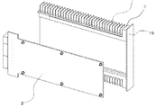
図1はこの発明に係る電子機器の第1の実施形態による電子機器の組立斜視図であり、図2は図1における断面AAを示す図である。図において、実施の形態1の電子機器筐体の放熱構造は、電子回路モジュール1および、それらを収納するシャーシ4より構成されている。
図1、図2において、4は上記電子回路モジュール1を収納するための箱状のシャーシで、電子回路モジュール1を着脱するための開口部5および電子回路モジュール1の保持を目的とし、電子回路モジュール1の挿入方向に矩形のスリット17が設けられている。また、シャーシ4は排気装置6および排気口7、並びに冷媒8をシャーシ4内部に取り込むための吸気口9が設けられている。
電子回路モジュール1はシャーシ4のスリット17に沿って挿入され、スリット17と電子回路モジュール1は隙間無く固定される。固定された電子回路モジュールの熱交換器10はスリット17より吸気口9と排気口7の間の空間に納置される。
Embodiment 1 FIG.
FIG. 1 is an assembled perspective view of an electronic device according to a first embodiment of the electronic device according to the present invention, and FIG. 2 is a view showing a cross section AA in FIG. In the figure, the heat dissipation structure of the electronic device casing of the first embodiment is composed of an electronic circuit module 1 and a chassis 4 for housing them.
1 and 2, reference numeral 4 denotes a box-shaped chassis for housing the electronic circuit module 1, for the purpose of holding the opening 5 for attaching and detaching the electronic circuit module 1 and the electronic circuit module 1. A
The electronic circuit module 1 is inserted along the
図3は実施の形態1における電子回路モジュール1の分解斜視図である。
本実施の形態における電子回路モジュール1は、熱交換器10が放熱板3の側面に設けられた熱交換器一体型放熱板16に、電子回路基板2が固定された構成を有する。
また、電子回路基板2は熱交換器一体型放熱板16に熱伝導性を持って結合されている。
FIG. 3 is an exploded perspective view of the electronic circuit module 1 according to the first embodiment.
The electronic circuit module 1 in the present embodiment has a configuration in which the
The
上記の様に構成された電子機器筐体の放熱構造においては、電子回路基板2で発生した熱は熱交換器一体型放熱板16に伝達され、熱交換器一体型放熱板16の内部を伝導してシャーシ4のスリット17間に位置する熱交換器10により冷媒8に放熱される。
In the heat dissipation structure of the electronic device casing configured as described above, the heat generated in the
ここで、従来の電子機器筐体の放熱構造と本構造を比較すると、本実施の形態に係る電子機器筐体の放熱構造では主放熱経路18(図2の破線)にシャーシ4と電子回路モジュールの接触面を含んでいない。
この結果、接触面における接触熱抵抗が解消されることで、放熱性能が向上する。
Here, when this structure is compared with the conventional heat dissipation structure of the electronic device casing, the chassis 4 and the electronic circuit module are arranged in the main heat dissipation path 18 (broken line in FIG. 2) in the heat dissipation structure of the electronic apparatus casing according to this embodiment. Does not include the contact surface.
As a result, heat dissipation performance is improved by eliminating contact thermal resistance on the contact surface.
実施の形態2.
実施の形態2に係る電子機器筐体の放熱構造は、基本的に実施の形態1と同様の構成を有している(図1)。図4は実施の形態2における、電子機器筐体の放熱構造の全体構成(図1)の断面AA相当の図を示している。
図4において、19、20はそれぞれ高発熱の電子回路モジュールおよび低発熱の電子回路モジュールである。高発熱の電子回路モジュール19、低発熱の電子回路モジュール20は実施形態1における電子回路モジュール1と基本構造は同一であるが、本実施の形態に係る電子機器筐体の放熱構造では、熱交換器一体型放熱板16の形状は電子回路モジュール毎の電子回路基板2上の部品配置や発熱量に応じて決定することができる。
また、熱交換器一体型放熱板16に設けられた熱交換器は、高発熱の電子回路モジュール19においては放熱性が高く、高圧力損失の熱交換器21が、低発熱の電子回路モジュール20においては21と比較して放熱性が低く、低圧力損失の熱交換器22が設けられている。
The heat dissipation structure of the electronic device casing according to the second embodiment basically has the same configuration as that of the first embodiment (FIG. 1). FIG. 4 shows a view corresponding to the cross section AA of the overall configuration (FIG. 1) of the heat dissipation structure of the electronic device casing in the second embodiment.
In FIG. 4, 19 and 20 are a high heat generation electronic circuit module and a low heat generation electronic circuit module, respectively. The electronic circuit module 19 with high heat generation and the electronic circuit module 20 with low heat generation have the same basic structure as the electronic circuit module 1 in the first embodiment. However, in the heat dissipation structure of the electronic device casing according to the present embodiment, heat exchange is performed. The shape of the unit-integrated
The heat exchanger provided on the heat exchanger integrated
このように、実施の形態2に係る電子機器筺体の放熱構造においては、実施の形態1の放熱構造で得られた接触熱抵抗の削減による冷却能力向上に加え、電子回路モジュールの発熱量に応じて熱交換器の圧力損失を変化させたことで、従来構造と比較して流路全体の総圧力損失が抑制される。したがって、総圧力損失低下により流路内の冷媒の流量は増加し、電子機器全体において高い放熱能力を得ることができる。 As described above, in the heat dissipation structure of the electronic device housing according to the second embodiment, in addition to the improvement of the cooling capability by the reduction of the contact thermal resistance obtained in the heat dissipation structure of the first embodiment, according to the heat generation amount of the electronic circuit module. By changing the pressure loss of the heat exchanger, the total pressure loss of the entire flow path is suppressed compared to the conventional structure. Therefore, the flow rate of the refrigerant in the flow path increases due to the decrease in the total pressure loss, and a high heat dissipation capability can be obtained in the entire electronic device.
1 電子回路モジュール、2 電子回路基板、3 放熱板、4 シャーシ、5 開口部、6 排気装置、7 排気口、8 冷媒、9 吸気口、10 熱交換器、11 ガイド溝、12 カードリテーナ、13 ガイド面、14 カバー、15 接触面、16 熱交換器一体型放熱板、17 スリット、18 放熱経路、19 高発熱の電子回路モジュール、20 低発熱の電子回路モジュール、21 高圧力損失の熱交換器、22 低圧力損失の熱交換器 DESCRIPTION OF SYMBOLS 1 Electronic circuit module, 2 Electronic circuit board, 3 Heat sink, 4 Chassis, 5 Opening part, 6 Exhaust device, 7 Exhaust port, 8 Refrigerant, 9 Intake port, 10 Heat exchanger, 11 Guide groove, 12 Card retainer, 13 Guide surface, 14 cover, 15 contact surface, 16 heat exchanger integrated heat sink, 17 slit, 18 heat dissipation path, 19 high heat generation electronic circuit module, 20 low heat generation electronic circuit module, 21 high pressure loss heat exchanger , 22 Low pressure loss heat exchanger
Claims (4)
電子回路基板を固定した複数の熱交換器一体型放熱板を収納可能な箱型のシャーシと、
から構成され、
前記熱交換器一体型放熱板は、前記電子回路基板を固定する放熱板部分と熱交換器とが接触しており、前記シャーシに設けられたスリットに沿って挿入された状態で固定されることを特徴とする電子機器筐体の放熱構造。 A heat exchanger integrated heat sink capable of fixing an electronic circuit board as a heating element;
A box-shaped chassis capable of storing a plurality of heat exchanger integrated heat sinks to which an electronic circuit board is fixed;
Consisting of
The heat exchanger integrated heat sink is fixed in a state in which a heat sink and a heat exchanger portion for fixing the electronic circuit board are in contact with each other and inserted along a slit provided in the chassis. A heat dissipation structure for an electronic device casing.
Priority Applications (1)
| Application Number | Priority Date | Filing Date | Title |
|---|---|---|---|
| JP2015064057A JP2016184657A (en) | 2015-03-26 | 2015-03-26 | Heat dissipation structure of electronic apparatus casing |
Applications Claiming Priority (1)
| Application Number | Priority Date | Filing Date | Title |
|---|---|---|---|
| JP2015064057A JP2016184657A (en) | 2015-03-26 | 2015-03-26 | Heat dissipation structure of electronic apparatus casing |
Publications (1)
| Publication Number | Publication Date |
|---|---|
| JP2016184657A true JP2016184657A (en) | 2016-10-20 |
Family
ID=57243153
Family Applications (1)
| Application Number | Title | Priority Date | Filing Date |
|---|---|---|---|
| JP2015064057A Pending JP2016184657A (en) | 2015-03-26 | 2015-03-26 | Heat dissipation structure of electronic apparatus casing |
Country Status (1)
| Country | Link |
|---|---|
| JP (1) | JP2016184657A (en) |
Cited By (2)
| Publication number | Priority date | Publication date | Assignee | Title |
|---|---|---|---|---|
| DE112017004745T5 (en) | 2016-09-21 | 2019-07-11 | Honda Motor Co., Ltd. | Wiper device and vehicle body rear structure |
| CN114222484A (en) * | 2021-12-20 | 2022-03-22 | 珠海格力电器股份有限公司 | Air conditioner |
Citations (2)
| Publication number | Priority date | Publication date | Assignee | Title |
|---|---|---|---|---|
| JPH10150284A (en) * | 1996-11-20 | 1998-06-02 | Yaskawa Electric Corp | Control unit |
| JP2005150539A (en) * | 2003-11-18 | 2005-06-09 | Mitsubishi Electric Corp | Electronic equipment |
-
2015
- 2015-03-26 JP JP2015064057A patent/JP2016184657A/en active Pending
Patent Citations (2)
| Publication number | Priority date | Publication date | Assignee | Title |
|---|---|---|---|---|
| JPH10150284A (en) * | 1996-11-20 | 1998-06-02 | Yaskawa Electric Corp | Control unit |
| JP2005150539A (en) * | 2003-11-18 | 2005-06-09 | Mitsubishi Electric Corp | Electronic equipment |
Cited By (2)
| Publication number | Priority date | Publication date | Assignee | Title |
|---|---|---|---|---|
| DE112017004745T5 (en) | 2016-09-21 | 2019-07-11 | Honda Motor Co., Ltd. | Wiper device and vehicle body rear structure |
| CN114222484A (en) * | 2021-12-20 | 2022-03-22 | 珠海格力电器股份有限公司 | Air conditioner |
Similar Documents
| Publication | Publication Date | Title |
|---|---|---|
| US10575433B2 (en) | Enclosure and cooling system for electronic equipment | |
| JP4859823B2 (en) | COOLING DEVICE AND ELECTRONIC DEVICE USING THE SAME | |
| US7492597B2 (en) | Structure for cooling a power adapter | |
| JP6626889B2 (en) | Liquid immersion cooled enclosure for electronic equipment | |
| US7804687B2 (en) | Liquid-cooled rack with pre-cooler and post-cooler heat exchangers used for EMI shielding | |
| TW201314425A (en) | Radiator device and electronic device using same | |
| US20160360641A1 (en) | Electronic device | |
| JP4714308B2 (en) | Electronics | |
| JP2008060515A (en) | Cooling device for electronic control device | |
| US10082850B2 (en) | Electronic device | |
| JP2016184657A (en) | Heat dissipation structure of electronic apparatus casing | |
| US10856444B2 (en) | Cooling device and electronic apparatus | |
| JP5619966B2 (en) | Heat dissipation structure | |
| JP5897478B2 (en) | Electronic equipment enclosure | |
| EP1971196B1 (en) | Clamshell enclosure for electronic circuit assemblies | |
| JP2012164743A (en) | On-vehicle electronic apparatus | |
| JP2007335624A (en) | Liquid-cooled cooler for electronic appliance | |
| JP2013131649A (en) | Heat radiation structure | |
| JP2014170765A (en) | Electronic device | |
| JP2017162892A (en) | Electronic device housing | |
| JP2012186203A (en) | Structure for cooling electronic apparatus casing | |
| US20220369505A1 (en) | Electronic apparatus cooling device, water-cooled information processing device, cooling module, and electronic apparatus cooling method | |
| JP2012256740A (en) | Electronic apparatus | |
| US8614892B2 (en) | Server with guiding air flow structure | |
| JP2018148188A (en) | Cooling device |
Legal Events
| Date | Code | Title | Description |
|---|---|---|---|
| A621 | Written request for application examination |
Free format text: JAPANESE INTERMEDIATE CODE: A621 Effective date: 20170120 |
|
| A131 | Notification of reasons for refusal |
Free format text: JAPANESE INTERMEDIATE CODE: A131 Effective date: 20171024 |
|
| A977 | Report on retrieval |
Free format text: JAPANESE INTERMEDIATE CODE: A971007 Effective date: 20171026 |
|
| A02 | Decision of refusal |
Free format text: JAPANESE INTERMEDIATE CODE: A02 Effective date: 20180417 |