JP2016120512A - Welding method and manufacturing method of weld member - Google Patents
Welding method and manufacturing method of weld member Download PDFInfo
- Publication number
- JP2016120512A JP2016120512A JP2014262414A JP2014262414A JP2016120512A JP 2016120512 A JP2016120512 A JP 2016120512A JP 2014262414 A JP2014262414 A JP 2014262414A JP 2014262414 A JP2014262414 A JP 2014262414A JP 2016120512 A JP2016120512 A JP 2016120512A
- Authority
- JP
- Japan
- Prior art keywords
- hole
- ring
- metal member
- opening edge
- opening
- Prior art date
- Legal status (The legal status is an assumption and is not a legal conclusion. Google has not performed a legal analysis and makes no representation as to the accuracy of the status listed.)
- Granted
Links
- 238000003466 welding Methods 0.000 title claims abstract description 54
- 238000000034 method Methods 0.000 title claims abstract description 29
- 238000004519 manufacturing process Methods 0.000 title claims abstract description 16
- 239000002184 metal Substances 0.000 claims abstract description 269
- 238000005304 joining Methods 0.000 claims abstract description 15
- 230000002093 peripheral effect Effects 0.000 claims description 50
- 230000001154 acute effect Effects 0.000 claims description 6
- 238000013459 approach Methods 0.000 claims description 6
- 230000005611 electricity Effects 0.000 abstract 1
- 239000000463 material Substances 0.000 description 6
- 238000010586 diagram Methods 0.000 description 2
- 230000020169 heat generation Effects 0.000 description 2
- 230000013011 mating Effects 0.000 description 2
- 238000003825 pressing Methods 0.000 description 1
Images


Abstract
Description
本発明は、溶接方法及び溶接部材の製造方法に関する。 The present invention relates to a welding method and a manufacturing method for a welded member.
リングプロジェクション溶接は、第1の金属部材に形成されたリング状突起の先端面と第2の金属部材の接合面とを接合する方法である。リングプロジェクション溶接を行う場合、第1の金属部材に形成されたリング状突起と第2の金属部材の接合面とを互いに押し付けつつ、第1の金属部材と第2の金属部材との間に電流を流す。すると、リング状突起が発熱して溶融する。溶融したリング状突起を介して、第1の金属部材と第2の金属部材とが接合される。 Ring projection welding is a method of joining the tip surface of the ring-shaped protrusion formed on the first metal member and the joint surface of the second metal member. When ring projection welding is performed, a current flows between the first metal member and the second metal member while pressing the ring-shaped protrusion formed on the first metal member and the joint surface of the second metal member against each other. Shed. Then, the ring-shaped protrusions generate heat and melt. The first metal member and the second metal member are joined through the melted ring-shaped protrusion.
特許文献1は、リングプロジェクション溶接の一例を開示する。特許文献1によれば、第1の金属部材に形成されたリング状突起の先端面と第2の金属部材の接合面とのいずれかに、相手側に向かって突出した凸形状部が設けられる。この凸形状部を相手側に押し付けた状態で両部材間に電流を流すことにより、両部材が接合される。 Patent Document 1 discloses an example of ring projection welding. According to Patent Document 1, a convex portion that protrudes toward the mating side is provided on either the tip surface of the ring-shaped protrusion formed on the first metal member or the joint surface of the second metal member. . Both members are joined by passing an electric current between both members in a state where the convex portion is pressed against the other side.
第1の金属部材の表面に形成された第1の孔の開口縁と第2の金属部材の表面に形成された第2の孔の開口縁とを従来のリングプロジェクション溶接により接合する場合、どちらかの孔の開口縁にリング状突起を予め形成しておかなければならない。孔の開口縁にリング状突起を形成するためには、孔が開口している表面を精度良く切り出し加工しなければならない。そのため、溶接される部材(以下、溶接対象部材)の製造工数及び製造コストが増大するという問題がある。 When joining the opening edge of the first hole formed on the surface of the first metal member and the opening edge of the second hole formed on the surface of the second metal member by conventional ring projection welding, A ring-shaped protrusion must be formed in advance on the opening edge of the hole. In order to form a ring-shaped protrusion on the opening edge of the hole, the surface on which the hole is open must be cut out with high accuracy. Therefore, there exists a problem that the manufacturing man-hour and manufacturing cost of the member (henceforth a welding object member) welded increase.
本発明は、溶接対象部材の製造工数及び製造コストを増加させることなく、2つの溶接対象部材のそれぞれの表面に形成された孔の開口縁どうしを接合することができる溶接方法、及び、そのような溶接方法を用いて製造される部材(以下、溶接部材)の製造方法を提供することを、目的とする。 The present invention provides a welding method capable of joining the opening edges of holes formed in the respective surfaces of two welding target members without increasing the manufacturing man-hours and manufacturing costs of the welding target members, and so on. It aims at providing the manufacturing method of the member (henceforth a welding member) manufactured using a simple welding method.
(課題を解決するための手段)
本発明は、第1の金属部材(10)に形成されている第1の表面(11)に開口した第1の孔(A1)の開口面と、第2の金属部材(20)に形成されている第2の表面(211a)に開口した第2の孔(A2)の開口面とが、所定の隙間を隔てて同軸状に対面するとともに、リング形状であるリング金具(R)が、第1の孔の開口縁に係合し且つ第2の孔の開口縁に係合した状態で第1の孔の開口縁と第2の孔の開口縁との間に挟まれるように、第1の金属部材、第2の金属部材、及びリング金具を配置させる配置工程と、第1の金属部材と第2の金属部材との間に電流を流すことにより、リング金具を介して第1の孔の開口縁と第2の孔の開口縁とを接合する接合工程と、を含む、溶接方法を提供する。
(Means for solving the problem)
The present invention is formed on the opening surface of the first hole (A1) opened on the first surface (11) formed on the first metal member (10) and on the second metal member (20). The opening surface of the second hole (A2) that opens to the second surface (211a) that faces the same coaxially with a predetermined gap therebetween, and the ring-shaped ring fitting (R) The first hole is engaged between the opening edge of the first hole and the opening edge of the second hole so as to be sandwiched between the opening edge of the first hole and the opening edge of the second hole. The first metal hole, the second metal member, and the ring metal fitting, and the first hole through the ring metal fitting by passing an electric current between the first metal member and the second metal member. And a joining step of joining the opening edge of the second hole and the opening edge of the second hole.
本発明によれば、第1の金属部材の第1の孔の開口面と、第2の金属部材の第2の孔の開口面が、所定の隙間を隔てて同軸状に対面配置される。また、第1の孔の開口縁と第2の孔の開口縁とにそれぞれ係合するように、リング形状を呈するリング金具が、第1の孔の開口縁と第2の孔の開口縁との間に挟まれる。そして、第1の金属部材と第2の金属部材との間に電流が流される。このとき第1の金属部材と第2の金属部材との間のリング金具にも電流が流れる。リング金具はそれぞれの金属部材の孔の開口縁にのみ係合しているため、リング金具を通過する電流の通過面積は小さい。このため電流がリング金具に集中することによりリング金具が発熱する。斯かる発熱によって、リング金具が溶融する。溶融したリング金具が第1の孔の開口縁及び第2の孔の開口縁にそれぞれ接合される。このようにして、リング金具を介して、第1の孔の開口縁と第2の孔の開口縁が溶接される。 According to the present invention, the opening surface of the first hole of the first metal member and the opening surface of the second hole of the second metal member are coaxially arranged with a predetermined gap therebetween. Further, the ring metal fitting having a ring shape is engaged with the opening edge of the first hole and the opening edge of the second hole, respectively, and the opening edge of the first hole and the opening edge of the second hole It is sandwiched between. And an electric current is sent between the 1st metal member and the 2nd metal member. At this time, a current also flows through the ring fitting between the first metal member and the second metal member. Since the ring fitting engages only with the opening edge of the hole of each metal member, the passage area of the current passing through the ring fitting is small. For this reason, when the current is concentrated on the ring fitting, the ring fitting generates heat. The ring fitting is melted by such heat generation. The fused ring fitting is joined to the opening edge of the first hole and the opening edge of the second hole, respectively. In this way, the opening edge of the first hole and the opening edge of the second hole are welded via the ring fitting.
つまり、本発明によれば、溶接対象部材とは別体のリング金具が、リングプロジェクション溶接に必要であるリング状突起の役割を果たす。このため、2つの溶接対象部材に形成されている孔の開口縁にリング状突起を形成することなく、2つの溶接対象部材のそれぞれの孔の開口縁どうしを溶接することができる。よって、溶接対象部材の製造工数及び製造コストを増加させることなく、2つの溶接対象部材のそれぞれの表面に形成された孔の開口縁どうしを接合することができる。 That is, according to the present invention, the ring metal member separate from the member to be welded serves as a ring-shaped protrusion necessary for ring projection welding. For this reason, the opening edges of the respective holes of the two welding target members can be welded to each other without forming ring-shaped protrusions at the opening edges of the holes formed in the two welding target members. Therefore, the opening edges of the holes formed on the respective surfaces of the two welding target members can be joined without increasing the manufacturing man-hours and manufacturing costs of the welding target members.
本発明に係るリング金具には、第1の孔の開口径よりも大きい外径及び第1の孔の開口径よりも小さい内径を有するとともに配置工程にて第1の孔の開口縁にその周方向に沿って係合するリング状の第1係合面(R1)と、第2の孔の開口径よりも大きい外径及び第2の孔の開口径よりも小さい内径を有するとともに配置工程にて第2の孔の開口縁にその周方向に沿って係合するリング状の第2係合面(R2)とが形成されているとよい。この場合、第1係合面及び第2係合面は、それらをリング金具の周方向に垂直な断面に表したときに、内周側から外周側に向かうにつれて互いに近づくように、リング金具の軸方向に垂直な平面に対してそれぞれ傾斜するように形成されているとよい。 The ring metal fitting according to the present invention has an outer diameter larger than the opening diameter of the first hole and an inner diameter smaller than the opening diameter of the first hole, and the circumference of the opening edge of the first hole in the arranging step. A ring-shaped first engagement surface (R1) that engages in a direction, an outer diameter that is larger than the opening diameter of the second hole, and an inner diameter that is smaller than the opening diameter of the second hole; In addition, a ring-shaped second engagement surface (R2) that engages along the circumferential direction of the opening edge of the second hole may be formed. In this case, when the first engagement surface and the second engagement surface are expressed in a cross-section perpendicular to the circumferential direction of the ring metal fitting, the ring fitting is arranged so as to approach each other from the inner circumference side toward the outer circumference side. It is good to form so that it may each incline with respect to a plane perpendicular | vertical to an axial direction.
これによれば、配置工程にてリング金具が第1の金属部材の第1の表面と第2の金属部材の第2の表面との間に挟まれたとき、リング金具の第1係合面のうち第1の孔の開口縁の径と同径の部分と第1の孔の開口縁とが線接触し、リング金具の第2係合面のうち第2の孔の開口縁の径と同径の部分と第2の孔の開口縁とが線接触する。このときリング金具の第1係合面は、第1の孔の開口面に対して傾斜し、リング金具の第2係合面は、第2の孔の開口面に対して傾斜する。 According to this, when the ring fitting is sandwiched between the first surface of the first metal member and the second surface of the second metal member in the arranging step, the first engagement surface of the ring fitting. Of the first hole and the opening edge of the first hole are in line contact with each other, and the diameter of the opening edge of the second hole of the second engagement surface of the ring fitting is The portion having the same diameter and the opening edge of the second hole are in line contact. At this time, the first engagement surface of the ring fitting is inclined with respect to the opening surface of the first hole, and the second engagement surface of the ring fitting is inclined with respect to the opening surface of the second hole.
このように、配置工程にて、リング金具の第1係合面を第1の金属部材の第1の孔の開口縁に線接触させることにより、第1係合面が第1の孔の開口縁に面接触する場合と比較して、接触面積が小さくされる。同様に、配置工程にて、リング金具の第2係合面を第2の金属部材の第2の孔の開口縁に線接触させることにより、第2係合面が第2の孔の開口縁に面接触する場合と比較して、接触面積が小さくされる。その結果、その後の接合工程にて、リング金具の第1係合面と第1の孔の開口縁との接触界面、及び、リング金具の第2係合面と第2の孔の開口縁との接触界面における電流密度をより高めることができる。これにより、接合工程にてリング金具を十分に発熱させることができ、リング金具を確実に溶融させることができる。また、リング金具が孔の開口縁に係合する位置がおのずと定められるので、第1の孔及び第2の孔に対してリング金具を精度よく位置決めすることができる。このため、リング金具の位置決め時間を短縮することができる。 In this manner, in the arranging step, the first engagement surface is opened to the first hole by bringing the first engagement surface of the ring metal into line contact with the opening edge of the first hole of the first metal member. The contact area is reduced as compared with the case where the edge is in surface contact. Similarly, in the arranging step, the second engagement surface is brought into line contact with the opening edge of the second hole of the second metal member so that the second engagement surface becomes the opening edge of the second hole. Compared with the case of surface contact, the contact area is reduced. As a result, in the subsequent joining step, the contact interface between the first engagement surface of the ring fitting and the opening edge of the first hole, and the second engagement surface of the ring fitting and the opening edge of the second hole The current density at the contact interface can be further increased. Thereby, a ring metal fitting can fully heat-generate in a joining process, and a ring metal fitting can be melted reliably. Further, since the position where the ring fitting engages with the opening edge of the hole is naturally determined, the ring fitting can be accurately positioned with respect to the first hole and the second hole. For this reason, the positioning time of a ring metal fitting can be shortened.
上記第1係合面及び第2係合面は、リング状の平面であってもよいし、リング状の曲面であってもよい。第1係合面及び第2係合面が平面である場合、例えば、リング金具の周方向に垂直な断面形状が三角形状あるいは菱形形状となるように、リング金具を形成することができる。また、第1係合面及び第2係合面が曲面である場合、例えば、リング金具の周方向に垂直な断面形状が円形状あるいは楕円形状となるように、リング金具を形成することができる。 The first engagement surface and the second engagement surface may be a ring-shaped flat surface or a ring-shaped curved surface. When the first engagement surface and the second engagement surface are flat surfaces, for example, the ring fitting can be formed such that the cross-sectional shape perpendicular to the circumferential direction of the ring fitting is a triangle shape or a rhombus shape. Further, when the first engagement surface and the second engagement surface are curved surfaces, for example, the ring fitting can be formed so that the cross-sectional shape perpendicular to the circumferential direction of the ring fitting is a circular shape or an elliptical shape. .
この場合、第1係合面及び第2係合面は、それぞれ平面形状であり、且つ、リング金具をその周方向に垂直な断面で表したときに、第1係合面を表す線分を含む直線と第2係合面を表す線分を含む直線とのなす角が鋭角であるように形成されるとよい。 In this case, each of the first engagement surface and the second engagement surface has a planar shape, and when the ring metal fitting is represented by a cross section perpendicular to the circumferential direction, a line segment representing the first engagement surface is obtained. It is preferable that the angle formed by the straight line including the straight line including the line segment representing the second engagement surface is an acute angle.
一般的に孔の開口縁には面取りが施されている。面取り面(C面)と開口面とのなす角(面取り角)は45°であることが多い。よって、第1係合面と第2係合面とのなす角が鋭角である場合、これらの係合面がC面の外周縁に係合することになる。リング金具の係合面が、孔の開口縁に形成されたC面の外周縁に係合した場合、リング金具の溶融時に溶融した部分がC面よりも外周側の部分、つまり、第1の金属部材の第1の表面と第2の金属部材の第2の表面との間の隙間部分に向かって引き伸ばされる。このため溶接代を大きくすることができる。その結果、溶接強度を高めることができる。 Generally, the opening edge of the hole is chamfered. The angle (chamfer angle) formed by the chamfered surface (C surface) and the opening surface is often 45 °. Therefore, when the angle formed by the first engagement surface and the second engagement surface is an acute angle, these engagement surfaces are engaged with the outer peripheral edge of the C surface. When the engagement surface of the ring fitting is engaged with the outer peripheral edge of the C surface formed at the opening edge of the hole, the portion melted when the ring fitting is melted is the portion on the outer peripheral side of the C surface, that is, the first It is stretched toward the gap between the first surface of the metal member and the second surface of the second metal member. For this reason, a welding allowance can be enlarged. As a result, the welding strength can be increased.
また、配置工程にて、リング金具が、第1の孔及び第2の孔に同軸配置するとよい。これによれば、接合工程にてリング金具の周方向に亘って均一に電流を流すことができる。その結果、リング金具を周方向に沿って均一に溶融させることができ、溶接ムラによる接合不良を防止することができる。 Further, in the arranging step, the ring metal fitting may be arranged coaxially with the first hole and the second hole. According to this, an electric current can be uniformly sent over the circumferential direction of a ring metal fitting in a joining process. As a result, the ring fitting can be uniformly melted along the circumferential direction, and joint failure due to welding unevenness can be prevented.
また、本発明は、第1の金属部材(10)に形成されている第1の表面(11)に開口した第1の孔(A1)の開口面と、第2の金属部材(20)に形成されている第2の表面(211a)に開口した第2の孔(A2)の開口面とが、所定の隙間を隔てて同軸状に対面するとともに、リング形状であるリング金具(R)が、第1の孔の開口縁に係合し且つ第2の孔の開口縁に係合した状態で第1の孔の開口縁と第2の孔の開口縁との間に挟まれるように、第1の金属部材、第2の金属部材、及びリング金具を配置させる配置工程と、第1の金属部材と第2の金属部材との間に電流を流すことにより、リング金具を介して第1の孔の開口縁と第2の孔の開口縁とを接合する接合工程と、を含む、溶接部材の製造方法を提供する。 Further, the present invention provides an opening surface of the first hole (A1) opened in the first surface (11) formed in the first metal member (10) and the second metal member (20). The opening surface of the second hole (A2) opened on the formed second surface (211a) faces coaxially with a predetermined gap, and the ring-shaped ring fitting (R) has a ring shape. Engaging the opening edge of the first hole and engaging the opening edge of the second hole so as to be sandwiched between the opening edge of the first hole and the opening edge of the second hole, An arrangement step of arranging the first metal member, the second metal member, and the ring metal fitting, and passing a current between the first metal member and the second metal member, thereby allowing the first metal member to pass through the ring metal fitting. And a joining step of joining the opening edge of the second hole and the opening edge of the second hole.
この場合、リング金具には、第1の孔の開口径よりも大きい外径及び第1の孔の開口径よりも小さい内径を有するとともに配置工程にて第1の孔の開口縁にその周方向に沿って係合するリング状の第1係合面と、第2の孔の開口径よりも大きい外径及び第2の孔の開口径よりも小さい内径を有するとともに配置工程にて第2の孔の開口縁にその周方向に沿って係合するリング状の第2係合面とが形成されており、第1係合面及び第2係合面は、それらをリング金具の周方向に垂直な断面に表したときに、内周側から外周側に向かうにつれて互いに近づくように、リング金具の軸方向に垂直な平面に対してそれぞれ傾斜するように形成されているとよい。また、第1係合面及び第2係合面は、それぞれ平面形状であり、且つ、リング金具の周方向に垂直な断面に表したときに、第1係合面を表す線分を含む直線と第2係合面を表す線分を含む直線とのなす角が鋭角であるように形成されるとよい。また、配置工程にて、リング金具が、第1の孔及び第2の孔に同軸配置するとよい。 In this case, the ring metal fitting has an outer diameter larger than the opening diameter of the first hole and an inner diameter smaller than the opening diameter of the first hole, and the circumferential direction on the opening edge of the first hole in the arranging step A ring-shaped first engaging surface that engages with the second hole, an outer diameter larger than the opening diameter of the second hole, and an inner diameter smaller than the opening diameter of the second hole. A ring-shaped second engagement surface that is engaged with the opening edge of the hole along the circumferential direction is formed, and the first engagement surface and the second engagement surface are arranged in the circumferential direction of the ring metal fitting. When expressed in a vertical cross section, it may be formed so as to be inclined with respect to a plane perpendicular to the axial direction of the ring metal fitting so as to approach each other from the inner peripheral side toward the outer peripheral side. The first engagement surface and the second engagement surface each have a planar shape, and a straight line including a line segment representing the first engagement surface when expressed in a cross section perpendicular to the circumferential direction of the ring metal fitting. And an angle formed by a straight line including a line segment representing the second engagement surface is preferably an acute angle. Further, in the arranging step, the ring metal fitting may be arranged coaxially with the first hole and the second hole.
上記発明によれば、溶接対象部材の製造工数及び製造コストを増加させることなく、2つの溶接対象部材のそれぞれの表面に形成された孔の開口縁どうしが接合された溶接部材を製造することができる。 According to the above invention, it is possible to manufacture a welding member in which the opening edges of the holes formed on the respective surfaces of the two welding target members are joined without increasing the manufacturing man-hours and manufacturing costs of the welding target members. it can.
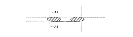
以下、本発明の実施形態につき説明する。図1は、本実施形態に係る溶接方法によって溶接される第1の金属部材10と第2の金属部材20とを示す図である。これらの部材が溶接対象部材である。図1に示すように、第1の金属部材10の外形形状は円柱形であり、第2の金属部材20の外形形状は直方体形である。本実施形態では、第1の金属部材10の材質と第2の金属部材20の材質は同一である。
Hereinafter, embodiments of the present invention will be described. FIG. 1 is a diagram showing a
円柱形の第1の金属部材10には、円形の一方端面11(第1の表面)と、一方端面11とは反対側に配置した円形の他方端面12と、両端面11,12の外周縁を結ぶ周面13とが形成される。また、第1の金属部材10には、3つの孔14,15,16(第1の孔)が形成されている。3つの孔14,15,16は、それぞれ第1の金属部材10の軸方向に平行な方向に延在し、両端面11,12にそれぞれ開口する。
The cylindrical
直方体形の第2の金属部材20には、正方形状の正面21と、正面21とは反対側に配置した正方形状の裏面22と、正面21と裏面22の外縁を結ぶ4つの側面23a,23b,23c,23dとが形成される。正面21の中央部分には、断面円形状の窪み211が形成されている。この窪み211の底面211a(第2の表面)の外形形状は、第1金属部材10の一方端面11の外形形状に一致する。従って、第1の金属部材10は、その一方端面11側の部分から第2の金属部材20の窪み211内に嵌め込まれることができる。
The rectangular parallelepiped
また、第2の金属部材20にも、3つの孔24,25,26(第2の孔)が形成されている。3つの孔24,25,26は、それぞれ第2の金属部材20の正面21及び裏面22の法線方向に延在し、それぞれの一方端が正面21に形成されている窪み211の底面211aに開口し、他方端が裏面22に開口する。
The
第1の金属部材10に形成されている3つの孔14,15,16の配置関係は、第2の金属部材20に形成されている3つの孔24,25,26の配置関係に一致する。すなわち、孔14の開口面と孔24の開口面とを同軸状に対面配置させたとき、孔15の開口面と孔25の開口面が同軸状に対面配置し、且つ、孔16の開口面と孔26の開口面が同軸状に対面配置する。また、本実施形態においては、孔14の開口径(直径)と孔24の開口径(直径)は等しく、孔15の開口径(直径)と孔25の開口径(直径)は等しく、孔16の開口径(直径)と孔26の開口径(直径)は等しい。以下、第1の金属部材10に形成されている3つの孔14,15,16を総称する場合、これらの孔をまとめて孔A1と呼び、第2の金属部材20に形成されている3つの孔24,25,26を総称する場合、それらの孔をまとめて孔A2と呼ぶ。
The arrangement relationship of the three
図2は、第1の金属部材10に形成されている孔A1の軸線を含む平面で第1の金属部材10を切断した場合における、第1の金属部材10の一方端面11への孔A1の開口部付近の断面図である。図2に示すように、一方端面11への孔A1の開口縁には、面取り面(C面)C1が、孔A1の周方向に沿ってリング状に形成されている。C面C1と孔A1の開口面とのなす角、すなわちC面C1の面取り角は、本実施形態においては、45°である。
FIG. 2 shows the hole A1 to the one
図3は、第2の金属部材20に形成されている孔A2の軸線を含む平面で第2の金属部材20を切断した場合における、第2の金属部材20の底面211aへの孔A2の開口部付近の断面図である。図3に示すように、底面211aへの孔A2の開口縁には面取り面(C面)C2が孔A2の周方向に沿ってリング状に形成されている。C面C2の面取り角は、本実施形態においては、45°である。
FIG. 3 shows the opening of the hole A2 to the
また、本実施形態においては、第1の金属部材10と第2の金属部材20とを溶接接合するために、3つのリング金具34,35,36が用いられる。リング金具34,35,36の材質は、本実施形態では、第1の金属部材10と第2の金属部材20の材質と同一である。以下、これらのリング金具34,35,36を総称する場合、単にリング金具Rと呼ぶ。
In the present embodiment, three
図4は、リング金具Rを示す図であり、図4(a)が正面図、図4(b)が背面図である。また、図4(c)は図4(a)の4c−4c断面図であり、リング金具Rの中心軸線を通る平面でリング金具Rを切断した場合における断面図である。図4(c)は、リング金具Rをその周方向に180°異なる2か所の位置で切断した場合における断面形状を表す。図4に示すように、リング金具Rには、円筒状の内周面R0と、第1係合面R1と、第2係合面R2とが形成されている。内周面R0により、リング金具Rの内周壁が構成される。第1係合面R1は、リング状の平面であり、内周面R0の一方の端を構成する円形状の端辺から径外方に向かって放射状に拡がるように形成される。第2係合面R2も、リング状の平面であり、内周面R0の他方の端を構成する円形状の端辺から径外方に向かって放射状に拡がるように形成される。
4A and 4B are diagrams showing the ring fitting R, where FIG. 4A is a front view and FIG. 4B is a rear view. 4C is a cross-sectional view taken along the
図4(c)に示すように、第1係合面R1は、その内周側から外周側に向かうにつれて、つまり径外方に向かうにつれて、リング金具Rの軸方向における中心位置を通り且つ上記軸方向に垂直な平面Pに近づくように、平面Pに対して傾斜している。同様に、第2係合面R2は、その内周側から外周側に向かうにつれて、つまり径外方に向かうにつれて、平面Pに近づくように、平面Pに対して傾斜している。従って、第1係合面R1と第2係合面R2は、それらを図4(c)に示すようにリング金具Rの周方向に垂直な断面に表したとき、リング金具Rの内周側から外周側に向かうにつれて互いに近づくように、リング金具Rの軸方向に垂直な平面Pに対してそれぞれ傾斜している。そして、平面P上の位置にて第1係合面R1と第2係合面R2が接続しており、その接続部分がリング金具Rの最外周にて円形の稜線を形成する。 As shown in FIG. 4 (c), the first engagement surface R1 passes through the center position in the axial direction of the ring fitting R as it goes from the inner circumference side toward the outer circumference side, that is, as it goes radially outward. It is inclined with respect to the plane P so as to approach the plane P perpendicular to the axial direction. Similarly, the second engagement surface R2 is inclined with respect to the plane P so as to approach the plane P from the inner peripheral side toward the outer peripheral side, that is, toward the radially outer side. Accordingly, when the first engagement surface R1 and the second engagement surface R2 are shown in a cross section perpendicular to the circumferential direction of the ring metal fitting R as shown in FIG. Are inclined with respect to a plane P perpendicular to the axial direction of the ring fitting R so as to approach each other as it goes from the outer periphery to the outer peripheral side. The first engagement surface R1 and the second engagement surface R2 are connected at a position on the plane P, and the connection portion forms a circular ridge line on the outermost periphery of the ring fitting R.
また、第1係合面R1と平面Pとのなす角、及び、第2係合面R2と平面Pとのなす角は、等しい。よって、リング金具Rを周方向に垂直な平面で切断した場合における、その切断箇所における断面形状は、二等辺三角形状である。そして、それぞれの二等辺三角形の2つの等辺が第1係合面R1及び第2係合面R2を表し、底辺が内周面R0を表す。 Further, the angle formed between the first engagement surface R1 and the plane P and the angle formed between the second engagement surface R2 and the plane P are equal. Therefore, when the ring metal fitting R is cut along a plane perpendicular to the circumferential direction, the cross-sectional shape at the cut portion is an isosceles triangle. The two equilateral sides of each isosceles triangle represent the first engagement surface R1 and the second engagement surface R2, and the bottom side represents the inner peripheral surface R0.
また、リング金具Rの断面を表す二等辺三角形の頂角の頂点が、第1係合面R1と第2係合面R2との接続部分を表す。この頂点の頂角は、リング金具Rをその周方向に垂直な断面で表したときにおける、第1係合面R1を表す線分を含む直線と第2係合面R2を表す線分を含む直線とのなす角である。この頂角は、本実施形態では鋭角、すなわち90°未満である。よって、リング金具Rの軸方向に垂直な平面と第1係合面R1とのなす角は45°未満となり、リング金具Rの軸方向に垂直な平面と第2係合面R2とのなす角も45°未満となる。 Further, the apex of the apex angle of the isosceles triangle representing the cross-section of the ring metal fitting R represents the connection portion between the first engagement surface R1 and the second engagement surface R2. The apex angle of the apex includes a straight line including the line segment representing the first engagement surface R1 and a line segment representing the second engagement surface R2 when the ring metal fitting R is represented by a cross section perpendicular to the circumferential direction. It is the angle formed by a straight line. In this embodiment, this apex angle is an acute angle, that is, less than 90 °. Therefore, the angle formed between the plane perpendicular to the axial direction of the ring fitting R and the first engagement surface R1 is less than 45 °, and the angle formed between the plane perpendicular to the axial direction of the ring fitting R and the second engagement surface R2. Is less than 45 °.
また、リング状の第1係合面R1の内径は孔A1の開口径(直径)よりも小さく、第1係合面R1の外径は孔A1の開口径よりも大きい。より具体的に言えば、第1係合面R1の内径は孔A1の開口縁に形成されているC面C1の外周径よりも小さく、第1係合面R1の外径はC面C1の外周径よりも大きい。また、リング状の第2係合面R2の内径は孔A2の開口径(直径)よりも小さく、第2係合面R2の外径は孔A2の開口径(直径)よりも大きい。より具体的に言えば、第2係合面R2の内径は孔A2の開口縁に形成されているC面C2の外周径よりも小さく、第2係合面R2の外径はC面C2の外周径よりも大きい。従って、リング金具Rは、孔A1の開口縁上及び孔A2の開口縁上に載置され得る。 The inner diameter of the ring-shaped first engagement surface R1 is smaller than the opening diameter (diameter) of the hole A1, and the outer diameter of the first engagement surface R1 is larger than the opening diameter of the hole A1. More specifically, the inner diameter of the first engagement surface R1 is smaller than the outer diameter of the C surface C1 formed at the opening edge of the hole A1, and the outer diameter of the first engagement surface R1 is the C surface C1. It is larger than the outer diameter. The inner diameter of the ring-shaped second engagement surface R2 is smaller than the opening diameter (diameter) of the hole A2, and the outer diameter of the second engagement surface R2 is larger than the opening diameter (diameter) of the hole A2. More specifically, the inner diameter of the second engagement surface R2 is smaller than the outer diameter of the C surface C2 formed at the opening edge of the hole A2, and the outer diameter of the second engagement surface R2 is the C surface C2. It is larger than the outer diameter. Accordingly, the ring fitting R can be placed on the opening edge of the hole A1 and on the opening edge of the hole A2.
本実施形態に係る溶接方法を実施する場合、第1の金属部材10、第2の金属部材20、及び3つのリング金具34,35,36を、抵抗溶接装置内に上下方向に対向配置されている上側電極と下側電極との間に配設する。この場合において、まず、第2の金属部材20の正面21が上方を向くように、第2の金属部材20を下側電極上に載置する。次いで、第2の金属部材20の正面21に形成された窪み211の底面211aに開口している孔24,25,26のうち、孔24の開口縁にリング金具34を、孔25の開口縁にリング金具35を、孔26の開口縁にリング金具36を、それぞれ配設する。
When carrying out the welding method according to the present embodiment, the
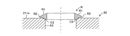
図5は、第2の金属部材20の底面211aに開口した孔A2の開口縁にリング金具Rが配設された状態を示す断面図である。図5に示すように、リング金具Rは、その軸方向が、孔A2の軸方向に一致するように、孔A2の開口縁に載置される。ここで、上記したように、リング金具Rの軸方向に垂直な平面とリング金具Rの第2係合面R2とのなす角(第2傾斜角)は45°未満である。第2傾斜角は、孔A2の開口縁に形成されたC面C2の面取り角(45°)よりも小さい。そのため、図5に示すように、リング金具Rの第2係合面R2は、C面C2の外周縁に係合し、C面C2の内周縁から浮き上がる。つまり、C面C2の外周縁のみが、第2係合面R2に接触する。また、第2係合面R2のうちC面C2の外周縁に係合する部分は、C面C2の外周径と同径の部分である。すなわち、C面C2の外周縁と、第2係合面R2のうちC面C2の外周径と同径の部分が、リング金具Rの周方向に沿って、線接触する。
FIG. 5 is a cross-sectional view showing a state in which the ring metal fitting R is disposed on the opening edge of the hole A2 opened in the
このように、リング金具Rの第2係合面R2が、リング金具Rの周方向に沿って、孔A2の開口縁(C面C2の外周縁)に線接触するため、第2係合面R2がC面C2に面接触する場合と比較して、接触面積を小さくすることができる。また、第2係合面R2のうちC面C2に係合する部分が定められることから、孔A2に対するリング金具Rの位置がおのずと定められる。つまり、リング金具Rが孔A2に対し容易に位置決めされる。このため孔A2に対するリング金具Rの位置決め時間が短縮される。孔A2に対してリング金具Rが位置決めされた場合、リング金具Rの軸心位置は、孔A2の軸心位置に一致する。つまり、リング金具Rが孔A2と同軸状に配置される。 As described above, the second engagement surface R2 of the ring metal fitting R is in line contact with the opening edge of the hole A2 (the outer peripheral edge of the C surface C2) along the circumferential direction of the ring metal fitting R. Compared to the case where R2 is in surface contact with C surface C2, the contact area can be reduced. Moreover, since the part engaged with C surface C2 is defined among 2nd engagement surfaces R2, the position of the ring metal fitting R with respect to the hole A2 is naturally determined. That is, the ring fitting R is easily positioned with respect to the hole A2. For this reason, the positioning time of the ring fitting R with respect to the hole A2 is shortened. When the ring fitting R is positioned with respect to the hole A2, the axial center position of the ring fitting R coincides with the axial center position of the hole A2. That is, the ring fitting R is arranged coaxially with the hole A2.
次いで、第1の金属部材10を、その一方端面11側から、第2の金属部材20の正面21に形成されている窪み211内に挿入する。この場合において、第1の金属部材10の一方端面11に開口している孔14の開口面が第2の金属部材20の窪み211の底面211aに開口している孔24の開口面に同軸状に対面し、一方端面11に開口している孔15の開口面が底面211aに開口している孔25の開口面に同軸状に対面し、一方端面11に開口している孔16の開口面が底面211aに開口している孔26の開口面に同軸状に対面するように、第2の金属部材20に対して第1の金属部材10を配置する。
Next, the
第2の金属部材20の孔24の開口縁にはリング金具34が配設されているので、第1の金属部材10の孔14の開口縁は、リング金具34にその上側から係合する。同様に、第2の金属部材20の孔25の開口縁にはリング金具35が配設されているので、第1の金属部材10の孔15の開口縁は、リング金具35にその上側から係合する。同様に、第2の金属部材20の孔26の開口縁にはリング金具36が配設されているので、第1の金属部材10の孔16の開口縁は、リング金具36にその上側から係合する。これにより、第1の金属部材10の孔A1の開口縁と、第2の金属部材20の孔A2の開口縁との間に、リング金具Rが挟まれる。
Since the ring fitting 34 is disposed at the opening edge of the
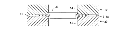
図6は、第1の金属部材10の孔A1の開口縁と、第2の金属部材20の孔A2の開口縁との間に、リング金具Rが挟まれた状態を示す断面図である。図6に示すように、リング金具Rは、その軸方向が、孔A1の軸方向及び孔A2の軸方向に一致するように、孔A1の開口縁と孔A2の開口縁との間に配設される。ここで、上記したように、リング金具Rの軸方向に垂直な平面とリング金具Rの第1係合面R1とのなす角(第1傾斜角)は45°未満である。第1傾斜角は、孔A1の開口縁に形成されたC面C1の面取り角(45°)よりも小さい。そのため、図6に示すように、リング金具Rの第1係合面R1は、C面C1の外周縁に係合し、C面C1の内周縁から浮き上がる。つまり、C面C1の外周縁のみが、第1係合面R1に接触する。また、第1係合面R1のうちC面C1の外周縁に係合する部分は、C面C1の外周径と同径の部分である。すなわち、C面C1の外周縁と、第1係合面R1のうちC面C1の外周径と同径の部分が、リング金具Rの周方向に沿って、線接触する。
FIG. 6 is a cross-sectional view showing a state in which the ring metal fitting R is sandwiched between the opening edge of the hole A1 of the
このように、リング金具Rの第1係合面R1が、リング金具Rの周方向に沿って、孔A1の開口縁(C面C1の外周縁)に線接触するため、第1係合面R1がC面C1に面接触する場合と比較して、接触面積を小さくすることができる。また、第1係合面R1のうちC面C1に係合する部分が定められることから、孔A1に対するリング金具Rの位置がおのずと定められる。つまり、リング金具Rが孔A1に対し容易に位置決めされる。このため孔A1に対するリング金具Rの位置決め時間が短縮される。孔A1に対してリング金具Rが位置決めされた場合、リング金具Rの軸心位置は、孔A1の軸心位置に一致する。つまり、リング金具Rが孔A1と同軸状に配置される。従って、リング金具Rは、孔A1及び孔A2と同軸状に配置される。 Thus, since the first engagement surface R1 of the ring metal fitting R is in line contact with the opening edge of the hole A1 (the outer peripheral edge of the C surface C1) along the circumferential direction of the ring metal fitting R, the first engagement surface. Compared with the case where R1 is in surface contact with C surface C1, the contact area can be reduced. Moreover, since the part engaged with C surface C1 is defined among 1st engagement surfaces R1, the position of the ring metal fitting R with respect to hole A1 is determined naturally. That is, the ring fitting R is easily positioned with respect to the hole A1. For this reason, the positioning time of the ring fitting R with respect to the hole A1 is shortened. When the ring fitting R is positioned with respect to the hole A1, the axial center position of the ring fitting R coincides with the axial center position of the hole A1. That is, the ring fitting R is arranged coaxially with the hole A1. Accordingly, the ring fitting R is arranged coaxially with the hole A1 and the hole A2.
また、第1の金属部材10の孔A1と第2の金属部材20の孔A2との間にリング金具Rが介在されているから、第1の金属部材10の孔A1の開口面と第2の金属部材20の孔A2の開口面とは、所定の隙間を隔てて対面配置することになる。すなわち、本実施形態によれば、第1の金属部材10に形成されている一方端面11の表面に開口した孔A1の開口面と、第2の金属部材20に形成されている底面211aに開口した孔A2の開口面とが、所定の隙間を隔てて同軸状に対面するとともに、リング形状であるリング金具Rが、孔A1の開口縁(C面C1の外周縁)に係合し且つ孔A2の開口縁(C面C2の外周縁)に係合した状態で孔A1の開口縁と孔A2の開口縁との間に挟まれるように、第1の金属部材10、第2の金属部材20、及びリング金具Rが配置される(配置工程)。
Further, since the ring metal fitting R is interposed between the hole A1 of the
なお、図6に示すように、リング金具Rが第1の孔A1の開口縁と第2の孔A2の開口縁との間に挟まれているときには、リング金具Rの第1係合面R1のうちC面C1の外周縁に係合している部分よりも内周側の部分は孔A1内に進入し、リング金具Rの第2係合面R2のうちC面C2の外周縁に係合している部分よりも内周側の部分は孔A2内に進入する。このため、第1の孔A1の開口縁と第2の孔A2の開口縁との間の隙間、すなわち一方端面11と底面211aとの間の隙間は、リング金具Rの軸方向における長さ(厚さ)よりも小さい。
As shown in FIG. 6, when the ring fitting R is sandwiched between the opening edge of the first hole A1 and the opening edge of the second hole A2, the first engagement surface R1 of the ring fitting R is shown. Of the second engagement surface R2 of the ring fitting R, a portion on the inner peripheral side of the portion engaged with the outer peripheral edge of the C surface C1 enters the hole A1, and is engaged with the outer peripheral edge of the C surface C2. The part on the inner peripheral side with respect to the joined part enters the hole A2. For this reason, the gap between the opening edge of the first hole A1 and the opening edge of the second hole A2, that is, the gap between the one
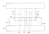
次に、第1の金属部材10の上側に設けられている上側電極を下降させる。これにより、第1の金属部材10、第2の金属部材20、及び3つのリング金具34,35,36が、抵抗溶接装置内の上側電極と下側電極との間に挟まれる。図7は、第1の金属部材10、第2の金属部材20、及び3つのリング金具34,35,36が、上側電極と下側電極との間に挟まれた状態を示す図である。図7に示すように、抵抗溶接装置内に設けられている上側電極41と下側電極42との間に、第1の金属部材10、第2の金属部材20、及び3つのリング金具34,35,36が組み合わせられた状態で、配設されている。また、第1の金属部材10の一方端面11に開口した孔14の開口縁と第2の金属部材20の底面211aに開口した孔24の開口縁との間にリング金具34が挟まれ、一方端面11に開口した孔15の開口縁と底面211aに開口した孔25の開口縁との間にリング金具35が挟まれ、一方端面11に開口した孔16の開口縁と底面211aに開口した孔26の開口縁との間にリング金具36が挟まれる。
Next, the upper electrode provided on the upper side of the
次いで、第1の金属部材10が第2の金属部材20に押し付けられるように、所定の加圧力(溶接荷重)を第1の金属部材10に付与する。そして、所定の溶接荷重が加えられた状態を維持しつつ、第1の金属部材10と第2の金属部材20との間に電圧を印加する。すると、第1の金属部材10と第2の金属部材20との間に電流が流れる。このとき第1の金属部材10と第2の金属部材20との間に介在するリング金具Rにも電流が流れる。上記したように、リング金具Rは、第1の金属部材10の孔A1の開口縁及び第2の金属部材20の孔A2の開口縁にそれぞれ線接触しているため、接触界面における電流の通過面積が小さい。このためリング金具Rを流れる電流の密度が高められる。こうしてリング金具Rに電流を集中させることによって、リング金具Rが発熱する。斯かる発熱によって、リング金具Rが溶融する。
Next, a predetermined pressure (welding load) is applied to the
図8は、孔A1の開口縁と孔A2の開口縁に挟まれたリング金具Rが溶融した状態を示す図である。図8に示すように、リング金具Rの溶融部分が、第1の金属部材10の一方端面11と第2の金属部材20の底面211aとの間の隙間であって、孔A1及び孔A2の開口縁の周りの領域に引き伸ばされる。また、リング金具Rの溶融に伴い、溶接荷重により第1の金属部材10の一方端面11と第2の金属部材20の底面211aとの間の隙間、すなわち孔A1の開口面と孔A2の開口面との間の隙間が狭められる。後述する実施例では、電圧を印加する前と後での上記隙間の変化量が、沈み込み量と呼ばれる。
FIG. 8 is a view showing a state where the ring fitting R sandwiched between the opening edge of the hole A1 and the opening edge of the hole A2 is melted. As shown in FIG. 8, the melted portion of the ring metal fitting R is a gap between the one
その後、リング金具Rの溶融部分が冷却固化すると、リング金具Rが第1の金属部材10の孔A1の開口縁及び第2の金属部材20の孔A2の開口縁に接合される。このようにして、リング金具Rを介して、孔A1の開口縁と孔A2の開口縁とが接合されるのである(接合工程)。
Thereafter, when the melted portion of the ring fitting R is cooled and solidified, the ring fitting R is joined to the opening edge of the hole A1 of the
図9は、リング金具Rを介して第1の金属部材10に形成されている孔A1の開口縁と第2の金属部材20に形成されている孔A2の開口縁とが接合されている状態を示す図である。図9に示すように、両開口縁間のリング金具Rが溶融することにより、両開口縁間の隙間が封止される。従って、孔A1と孔A2とによって連通路Lが形成される。形成された連通路Lの内壁のうち、孔A1の開口縁と孔A2の開口縁との繋ぎ目の部分には、リング金具Rの内周部分が突出している。
FIG. 9 shows a state in which the opening edge of the hole A1 formed in the
このように、本実施形態は、上記した配置工程及び接合工程を経て、第1の金属部材10に形成されている孔A1の開口縁と、第2の金属部材20に形成されている孔A2の開口縁とをリング金具Rを介して接合する溶接方法を開示する。また、本実施形態は、上記した配置工程及び接合工程を経て、第1の金属部材10に形成されている孔A1の開口縁と、第2の金属部材20に形成されている孔A2の開口縁とがリング金具Rを介して接合されてなる溶接部材の製造方法を開示する。
As described above, in the present embodiment, the opening edge of the hole A1 formed in the
(実施例)
3つの孔14,15,16が形成されている第1の金属部材10と、3つの孔24,25,26が形成されている第2の金属部材20と、3つのリング金具34,35,36を用意した。ここで、孔14及び孔24の開口径(直径)はいずれも12mmであり、孔15、孔25、孔16、孔26の開口径(直径)はいずれも10mmである。また、リング金具34,35,36の断面形状(周方向に垂直な平面で切断した場合における断面形状)は、いずれも図4(c)に示すような二等辺三角形である。また、リング金具34の外径は16mm、内径は10mm、厚さ(軸方向長さ)は6mmであり、リング金具35及び36の外径は14mm、内径は8mm、厚さは6mmである。
(Example)
The
次に、第1の金属部材10に形成されている孔14の開口面と第2の金属部材20に形成されている孔24の開口面とを同軸状に対面配置させるとともに、孔14の開口縁と孔24の開口縁との間にリング金具34を同軸状に配設した。また、第1の金属部材10に形成されている孔15の開口面と第2の金属部材に形成されている孔25の開口面とを同軸状に対面配置させるとともに、孔15の開口縁と孔25の開口縁との間にリング金具35を同軸状に配設した。さらに、第1の金属部材10に形成されている孔16の開口面と第2の金属部材20に形成されている孔26の開口面とを同軸状に対面配置させるとともに、孔16の開口縁と孔26の開口縁との間にリング金具36を同軸状に配設した。そして、第1の金属部材10と第2の金属部材20とを2つの電極によって挟み、所定の溶接荷重を加えるとともに、第1の金属部材10と第2の金属部材20との間に電圧を印加して、第1の金属部材10と第2の金属部材との間に電流(溶接電流)を流した。これにより各孔の開口縁どうしを抵抗溶接した。この場合における溶接条件は以下の通りである。
・溶接電流:21kA
・溶接荷重:450kgf
・通電時間200msec.
・沈み込み量:2mm
Next, the opening surface of the
・ Welding current: 21 kA
・ Welding load: 450kgf
-Energizing time 200 msec.
・ Subduction amount: 2mm
上記の条件により抵抗溶接したところ、孔14の開口縁と孔24の開口縁、孔15の開口縁と孔25の開口縁、及び、孔16の開口縁と孔26の開口縁が、いずれも良好に接合されて、2つの孔を繋いだ連通路が形成された。また、各孔の開口縁が周方向に沿って均一に溶接されており、周方向における溶接ムラはほとんど発生しなかった。
When resistance welding was performed under the above conditions, the opening edge of the
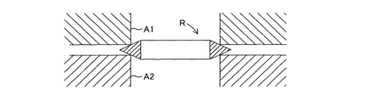
以上、本発明の実施形態について説明したが、本発明は、上記実施形態に限定されるものではない。例えば、上記実施形態においては、溶接される孔の開口縁にC面が形成されている例を示したが、本発明は、図10に示すように、C面が形成されていない孔A1の開口縁とC面が形成されていない孔A2の開口縁とを、リング金具Rを介して溶接することもできる。 As mentioned above, although embodiment of this invention was described, this invention is not limited to the said embodiment. For example, in the said embodiment, although the C surface was formed in the opening edge of the hole to be welded, as shown in FIG. 10, this invention is the hole A1 in which the C surface is not formed. It is also possible to weld the opening edge and the opening edge of the hole A2 where the C-plane is not formed via the ring fitting R.
また、上記実施形態においては、リング金具Rの断面(周方向に垂直な平面で切断した場合における断面)形状が二等辺三角形である例を示したが、その他の三角形でもよいし、三角形以外の断面形状でもよい。例えば、図11に示すように、菱形の断面形状を有するリング金具Rを用いてもよい。 Moreover, in the said embodiment, although the cross-section (section in the case of cut | disconnecting in the plane perpendicular | vertical to the circumferential direction) shape of the ring metal fitting R was shown, the example which is an isosceles triangle was shown, Other triangles may be sufficient. A cross-sectional shape may be used. For example, as shown in FIG. 11, a ring fitting R having a diamond-shaped cross section may be used.
また、上記実施形態においては、リング金具Rに形成されている第1係合面R1と第2係合面R2がともに平面である例を示したが、第1係合面R1と第2係合面R2は、曲面であってもよい。この場合、図12に示すように、円形の断面形状を有するリング金具Rを用いてもよいし、図13に示すように、楕円形の断面形状を有するリング金具Rを用いてもよい。つまり、リング金具Rは、孔の開口縁に係合することができるような係合面が形成されていれば、如何なる断面形状であってもよい。 Moreover, in the said embodiment, although the 1st engagement surface R1 and 2nd engagement surface R2 which were formed in the ring metal fitting R both showed the plane, the 1st engagement surface R1 and the 2nd engagement surface were shown. The mating surface R2 may be a curved surface. In this case, a ring fitting R having a circular cross-sectional shape may be used as shown in FIG. 12, or a ring fitting R having an elliptical cross-sectional shape may be used as shown in FIG. That is, the ring fitting R may have any cross-sectional shape as long as an engagement surface capable of engaging with the opening edge of the hole is formed.
また、本発明に係るリング金具Rは、図14に示すように、内周面R0、第1係合面R1、第2係合面R2に加え、外周壁を構成する外周面R3を有するように構成されていてもよい。この場合、リング金具Rをその周方向に垂直な平面で切断した場合の断面形状が台形状にされ、その下底が内周面R0を表し、上底が外周面R3を表し、一対の脚が第1係合面R1及び第2係合面R2を表す。また、上記断面における第1係合面R1を表す線分を含む直線と第2係合面R2を表す線分を含む直線とのなす角は、鋭角であるとよい。 Further, as shown in FIG. 14, the ring fitting R according to the present invention has an outer peripheral surface R3 constituting an outer peripheral wall in addition to the inner peripheral surface R0, the first engagement surface R1, and the second engagement surface R2. It may be configured. In this case, the cross-sectional shape when the ring fitting R is cut along a plane perpendicular to the circumferential direction thereof is trapezoidal, the lower bottom represents the inner circumferential surface R0, the upper bottom represents the outer circumferential surface R3, and a pair of legs Represents the first engagement surface R1 and the second engagement surface R2. In addition, the angle formed by the straight line including the line segment representing the first engagement surface R1 and the straight line including the line segment representing the second engagement surface R2 in the cross section may be an acute angle.
また、上記実施形態では、同径の孔の開口縁どうしを溶接する例を例示したが、異なる径の孔の開口縁どうしを溶接することもできる。この場合、図15に示すようにリング金具Rを形成すればよい。図15に示すリング金具Rによれば、孔A1の開口縁が第1係合面R1に係合し、孔A2の開口縁が第2係合面R2に係合する。また、第1係合面R1の外径が孔A1の開口径(直径)よりも大きく、第1係合面R1の内径がA1の開口径よりも小さくなるように、第1係合面R1が形成され、第2係合面R2の外径が孔A2の開口径(直径)よりも大きく、第2係合面R2の内径が孔A2の開口径(直径)よりも小さくなるように、第2係合面R2が形成される。また、リング金具Rの軸方向に垂直な面に対する第1係合面R1の傾斜角度と第2係合面R2の傾斜角度が異なっている。具体的には、大きい開口径を有する孔(孔A2)の開口縁(C面の外周縁)に係合する第2係合面R2の傾斜角が、小さい開口径を有する孔(孔A1)の開口縁(C面の外周縁)に係合する第1係合面R1の傾斜角よりも大きくされている。このようなリング金具Rを用いることにより、径の異なる孔の開口縁どうしを接合することができる。また、上記実施形態では、第1の金属部材10、第2の金属部材20、及びリング金具Rの材質は同一であるが、リング金具Rを介して第1の金属部材10の孔A1の開口縁と第2の金属部材20の開口縁を溶接することができる限り、これらが異なる材質で構成されていてもよい。このように、本発明は、その趣旨を逸脱しない限りにおいて、変形可能である。
Moreover, although the example which welds the opening edges of the hole of the same diameter was illustrated in the said embodiment, the opening edges of the hole of a different diameter can also be welded. In this case, the ring fitting R may be formed as shown in FIG. According to the ring fitting R shown in FIG. 15, the opening edge of the hole A1 engages with the first engagement surface R1, and the opening edge of the hole A2 engages with the second engagement surface R2. In addition, the first engagement surface R1 is such that the outer diameter of the first engagement surface R1 is larger than the opening diameter (diameter) of the hole A1, and the inner diameter of the first engagement surface R1 is smaller than the opening diameter of A1. Are formed so that the outer diameter of the second engagement surface R2 is larger than the opening diameter (diameter) of the hole A2, and the inner diameter of the second engagement surface R2 is smaller than the opening diameter (diameter) of the hole A2. A second engagement surface R2 is formed. Further, the inclination angle of the first engagement surface R1 and the inclination angle of the second engagement surface R2 with respect to the surface perpendicular to the axial direction of the ring fitting R are different. Specifically, the hole (hole A1) having a small opening diameter with the inclination angle of the second engagement surface R2 engaged with the opening edge (outer peripheral edge of the C surface) of the hole (hole A2) having a large opening diameter. It is made larger than the inclination-angle of 1st engagement surface R1 engaged with the opening edge (outer periphery of C surface). By using such a ring metal fitting R, it is possible to join opening edges of holes having different diameters. Moreover, in the said embodiment, although the material of the
10…第1の金属部材、11…一方端面(第1の表面)、12…他方端面、13…周面、14,15,16,A1…孔(第1の孔)、C1…C面(開口縁)、20…第2の金属部材、21…正面、211…窪み、211a…底面(第2の表面)、22…裏面、23a,23b,23c,23d…側面、24,25,26,A2…孔(第2の孔)、C2…C面(開口縁)、34,35,36,R…リング金具、R0…内周面、R1…第1係合面、R2…第2係合面、R3…外周面、41…上側電極、42…下側電極
DESCRIPTION OF
Claims (5)
前記第1の金属部材と前記第2の金属部材との間に電流を流すことにより、前記リング金具を介して前記第1の孔の開口縁と前記第2の孔の開口縁とを接合する接合工程と、
を含む、溶接方法。 The opening surface of the first hole opened in the first surface formed in the first metal member and the opening surface of the second hole opened in the second surface formed in the second metal member And a ring-shaped ring fitting engaged with the opening edge of the first hole and the opening edge of the second hole. An arrangement step of arranging the first metal member, the second metal member, and the ring fitting so as to be sandwiched between the opening edge of the first hole and the opening edge of the second hole. When,
By passing an electric current between the first metal member and the second metal member, the opening edge of the first hole and the opening edge of the second hole are joined via the ring fitting. Joining process;
Including a welding method.
前記リング金具には、前記第1の孔の開口径よりも大きい外径及び前記第1の孔の開口径よりも小さい内径を有するとともに前記配置工程にて前記第1の孔の開口縁にその周方向に沿って係合するリング状の第1係合面と、前記第2の孔の開口径よりも大きい外径及び前記第2の孔の開口径よりも小さい内径を有するとともに前記配置工程にて前記第2の孔の開口縁にその周方向に沿って係合するリング状の第2係合面とが形成されており、
前記第1係合面及び前記第2係合面は、それらを前記リング金具の周方向に垂直な断面に表したときに、内周側から外周側に向かうにつれて互いに近づくように、前記リング金具の軸方向に垂直な平面に対してそれぞれ傾斜するように形成されている、
溶接方法。 The welding method according to claim 1,
The ring metal fitting has an outer diameter larger than the opening diameter of the first hole and an inner diameter smaller than the opening diameter of the first hole, and is arranged at the opening edge of the first hole in the arranging step. The disposing step has a ring-shaped first engagement surface that engages along a circumferential direction, an outer diameter that is larger than an opening diameter of the second hole, and an inner diameter that is smaller than the opening diameter of the second hole. And a ring-shaped second engagement surface that is engaged with the opening edge of the second hole along the circumferential direction thereof.
When the first engagement surface and the second engagement surface are expressed in a cross section perpendicular to the circumferential direction of the ring metal fitting, the ring metal fitting approaches each other from the inner peripheral side toward the outer peripheral side. Formed so as to be inclined with respect to a plane perpendicular to the axial direction of
Welding method.
前記第1係合面及び前記第2係合面は、それぞれリング状の平面であり、
前記リング金具をその周方向に垂直な断面で表したときに、前記第1係合面を表す線分を含む直線と前記第2係合面を表す線分を含む直線とのなす角が鋭角であるように、前記第1係合面及び前記第2係合面が形成される、溶接方法。 The welding method according to claim 2,
Each of the first engagement surface and the second engagement surface is a ring-shaped plane,
When the ring metal fitting is represented by a cross section perpendicular to the circumferential direction, an angle formed by a straight line including a line segment representing the first engagement surface and a straight line including a line segment representing the second engagement surface is an acute angle. The welding method, wherein the first engagement surface and the second engagement surface are formed.
前記配置工程にて、前記リング金具が、前記第1の孔及び前記第2の孔に同軸配置する、溶接方法。 The welding method according to any one of claims 1 to 3,
The welding method in which the ring fitting is coaxially arranged in the first hole and the second hole in the arranging step.
前記第1の金属部材と前記第2の金属部材との間に電流を流すことにより、前記リング金具を介して前記第1の孔の開口縁と前記第2の孔の開口縁とを接合する接合工程と、
を含む、溶接部材の製造方法。 The opening surface of the first hole opened in the first surface formed in the first metal member and the opening surface of the second hole opened in the second surface formed in the second metal member And a ring-shaped ring fitting engaged with the opening edge of the first hole and the opening edge of the second hole. An arrangement step of arranging the first metal member, the second metal member, and the ring fitting so as to be sandwiched between the opening edge of the first hole and the opening edge of the second hole. When,
By passing an electric current between the first metal member and the second metal member, the opening edge of the first hole and the opening edge of the second hole are joined via the ring fitting. Joining process;
The manufacturing method of the welding member containing this.
Priority Applications (1)
| Application Number | Priority Date | Filing Date | Title |
|---|---|---|---|
| JP2014262414A JP6520113B2 (en) | 2014-12-25 | 2014-12-25 | Welding method and manufacturing method of welding member |
Applications Claiming Priority (1)
| Application Number | Priority Date | Filing Date | Title |
|---|---|---|---|
| JP2014262414A JP6520113B2 (en) | 2014-12-25 | 2014-12-25 | Welding method and manufacturing method of welding member |
Publications (2)
| Publication Number | Publication Date |
|---|---|
| JP2016120512A true JP2016120512A (en) | 2016-07-07 |
| JP6520113B2 JP6520113B2 (en) | 2019-05-29 |
Family
ID=56327899
Family Applications (1)
| Application Number | Title | Priority Date | Filing Date |
|---|---|---|---|
| JP2014262414A Expired - Fee Related JP6520113B2 (en) | 2014-12-25 | 2014-12-25 | Welding method and manufacturing method of welding member |
Country Status (1)
| Country | Link |
|---|---|
| JP (1) | JP6520113B2 (en) |
Citations (3)
| Publication number | Priority date | Publication date | Assignee | Title |
|---|---|---|---|---|
| JPS58184064A (en) * | 1982-04-23 | 1983-10-27 | Hitachi Ltd | Brazing of metallic member |
| JPS6152996A (en) * | 1984-08-21 | 1986-03-15 | Kobe Steel Ltd | Method of joining stainless steel to ti base or zr base metal |
| JPH0734965A (en) * | 1993-07-20 | 1995-02-03 | Yamaha Motor Co Ltd | Joining structure of valve seat |
-
2014
- 2014-12-25 JP JP2014262414A patent/JP6520113B2/en not_active Expired - Fee Related
Patent Citations (3)
| Publication number | Priority date | Publication date | Assignee | Title |
|---|---|---|---|---|
| JPS58184064A (en) * | 1982-04-23 | 1983-10-27 | Hitachi Ltd | Brazing of metallic member |
| JPS6152996A (en) * | 1984-08-21 | 1986-03-15 | Kobe Steel Ltd | Method of joining stainless steel to ti base or zr base metal |
| JPH0734965A (en) * | 1993-07-20 | 1995-02-03 | Yamaha Motor Co Ltd | Joining structure of valve seat |
Also Published As
| Publication number | Publication date |
|---|---|
| JP6520113B2 (en) | 2019-05-29 |
Similar Documents
| Publication | Publication Date | Title |
|---|---|---|
| US8722252B2 (en) | Current carrying block for resistance welding, and method for manufacturing sealed battery and sealed battery each using the current carrying block | |
| CN103038017B (en) | The method be connected with wheel hub axle by welding current and press-in and axle and wheel hub are by this device connected and composed | |
| JP7157956B2 (en) | Cylindrical battery and manufacturing method thereof | |
| US9897063B2 (en) | Glow plug with pressure sensor | |
| JP6553604B2 (en) | Fittings enabling nondestructive pressure testing of seal integrity | |
| CN100485997C (en) | Sealed battery and manufacturing method therefor | |
| JP2014026927A (en) | Secondary battery and manufacturing method therefor | |
| JP2016110859A (en) | Current cutoff device and secondary battery | |
| US3076261A (en) | Self-leveling welding ring with projecting ears | |
| US10549377B2 (en) | Welding assistance member and spot-welding method using welding assistance member | |
| JP2016120512A (en) | Welding method and manufacturing method of weld member | |
| US20130095370A1 (en) | Battery assembly production method and battery assembly | |
| JP6530903B2 (en) | Method of manufacturing welded body and method of manufacturing gas sensor | |
| JP2013535634A (en) | Internal electrofusion ring coupler | |
| KR20140005001U (en) | Electonic melting type socket for connecting gas pipe | |
| US20100288736A1 (en) | Weld stud | |
| US20220123393A1 (en) | Battery and method of manufacturing same | |
| JP6608787B2 (en) | Manufacturing method of sealed battery | |
| CN106132667B (en) | The welding process of resin forming product | |
| JP2007301577A (en) | Cylindrical product | |
| JPS61248356A (en) | Universal seal | |
| JP2021080988A (en) | nut | |
| JP2015205291A (en) | Weld state determination device and weld state determination method | |
| JP5482756B2 (en) | Secondary battery and method for manufacturing secondary battery | |
| KR101959051B1 (en) | Fixing method by pipe bush with separated flange for electronic vehicles |
Legal Events
| Date | Code | Title | Description |
|---|---|---|---|
| A621 | Written request for application examination |
Free format text: JAPANESE INTERMEDIATE CODE: A621 Effective date: 20171110 |
|
| A977 | Report on retrieval |
Free format text: JAPANESE INTERMEDIATE CODE: A971007 Effective date: 20180904 |
|
| A131 | Notification of reasons for refusal |
Free format text: JAPANESE INTERMEDIATE CODE: A131 Effective date: 20181003 |
|
| A521 | Request for written amendment filed |
Free format text: JAPANESE INTERMEDIATE CODE: A523 Effective date: 20181114 |
|
| TRDD | Decision of grant or rejection written | ||
| A01 | Written decision to grant a patent or to grant a registration (utility model) |
Free format text: JAPANESE INTERMEDIATE CODE: A01 Effective date: 20190402 |
|
| A61 | First payment of annual fees (during grant procedure) |
Free format text: JAPANESE INTERMEDIATE CODE: A61 Effective date: 20190415 |
|
| R151 | Written notification of patent or utility model registration |
Ref document number: 6520113 Country of ref document: JP Free format text: JAPANESE INTERMEDIATE CODE: R151 |
|
| LAPS | Cancellation because of no payment of annual fees |