JP2016013600A - Machine tool - Google Patents
Machine tool Download PDFInfo
- Publication number
- JP2016013600A JP2016013600A JP2014137255A JP2014137255A JP2016013600A JP 2016013600 A JP2016013600 A JP 2016013600A JP 2014137255 A JP2014137255 A JP 2014137255A JP 2014137255 A JP2014137255 A JP 2014137255A JP 2016013600 A JP2016013600 A JP 2016013600A
- Authority
- JP
- Japan
- Prior art keywords
- axis direction
- bed
- machine
- disposed
- axis
- Prior art date
- Legal status (The legal status is an assumption and is not a legal conclusion. Google has not performed a legal analysis and makes no representation as to the accuracy of the status listed.)
- Granted
Links
Images


Abstract
Description
本発明は、傾斜支持面上で旋回することで直交する2軸線回りに回転可能に構成された傾斜テーブルと、軸線方向に移動可能に構成された主軸とを備えた工作機械に関する。 The present invention relates to a machine tool including an inclination table configured to be rotatable around two orthogonal axes by turning on an inclined support surface, and a main shaft configured to be movable in the axial direction.
ワークが搭載されるテーブル本体を直交する2軸線回りに回転可能とする傾斜テーブルと、軸線方向に移動可能に構成された主軸とを備えた工作機械がある(例えば特許文献1,2参照)。この従来の工作機械では、主軸をY軸方向及びZ軸方向に移動可能に構成すると共に、傾斜テーブルをX軸方向に移動可能に構成している。
There is a machine tool including a tilting table that allows a table body on which a workpiece is mounted to be rotated about two orthogonal axes and a spindle that is configured to be movable in the axial direction (see, for example,
ところで、例えば近年の自動車用部品の機械加工においては、工具交換装置を備えた複数の前記工作機械を並列に配置し、各工作機械間でワークを受渡ししながら順次加工を加える加工ラインを形成する場合がある。この場合、複数の工作機械の設置に必要な設置面積をできるだけ削減することが要請されている。 By the way, in recent machining of automobile parts, for example, a plurality of the machine tools provided with a tool changer are arranged in parallel, and a machining line is formed in which machining is sequentially performed while delivering workpieces between the machine tools. There is a case. In this case, it is required to reduce the installation area necessary for installing a plurality of machine tools as much as possible.
ところが従来の工作機械では、工具交換装置に備えられた工具を手動で交換する場合、オペレータが機械の側面から工具交換装置にアクセスするように構成されているので、オペレータの作業スペースを隣接する工作機械間に設ける必要があるため、前記設置面積の削減にはおのずと限界があった。 However, in the conventional machine tool, when the tool provided in the tool changer is manually changed, the operator accesses the tool changer from the side of the machine. Since it is necessary to provide between machines, there was a limit in reducing the installation area.
また、前記傾斜テーブルを備えた工作機械では、ワークが搭載されるテーブル本体が傾斜支持面によって支持されているので、テーブル本体が水平支持面に支持されている場合に比較して主軸によるZ軸方向の切削荷重を効率よく負担することができる。一方、近年の機械のコンパクト化のさらなる要請に鑑み、前記主軸からの切削荷重のさらなる効率的な負担を可能とする構造が要請される。 Further, in the machine tool provided with the tilt table, the table body on which the workpiece is mounted is supported by the tilt support surface, so that the Z axis by the main shaft is compared with the case where the table body is supported by the horizontal support surface. The cutting load in the direction can be efficiently borne. On the other hand, in view of further demands for downsizing of machines in recent years, there is a demand for a structure that enables more efficient burden of cutting load from the spindle.
本発明は、前記従来の状況に鑑みてなされたもので、複数の工作機械を並列配置する場合の設置面積を削減できる工作機械を提供することを課題としている。 The present invention has been made in view of the above-described conventional situation, and an object thereof is to provide a machine tool capable of reducing an installation area when a plurality of machine tools are arranged in parallel.
請求項1の発明は、ベッド上に搭載されたベース部材の傾斜支持面上に旋回部材を旋回可能に配設し、該旋回部材にテーブル本体を回転可能に配設した傾斜テーブルと、
前記ベッド上に軸線方向に移動可能に配設された主軸とを備えた工作機械において、
前記主軸は、機械正面視で、前記ベッド上の奥側に、左右方向(X軸方向),上下方向(Y軸方向)及び主軸軸線方向(Z軸方向)のうち少なくもX軸方向及びY軸方向に移動可能に配設され、
前記傾斜テーブルは、前記ベッド上の手前側に、前記Z軸方向に移動可能に、又は固定して配設され、
前記ベッドの奥側かつ側部に工具交換装置が配設され、
前記ベッドの、前記工具交換装置が配設された側で、かつ前記傾斜テーブルの側方部分に、オペレータが機械正面から前記工具交換装置にアクセス可能とするアクセススペースを設けたことを特徴としている。
The invention according to
In a machine tool comprising a spindle disposed on the bed so as to be movable in the axial direction,
The main shaft is at least one of the left-right direction (X-axis direction), the up-down direction (Y-axis direction), and the main-axis axis direction (Z-axis direction) on the back side of the bed in the machine front view. It is arranged to be movable in the axial direction,
The inclined table is arranged on the front side of the bed so as to be movable or fixed in the Z-axis direction,
A tool changer is disposed on the back side and the side of the bed,
The bed is provided with an access space on the side where the tool changer is disposed and on a side portion of the inclined table so that an operator can access the tool changer from the front of the machine. .
請求項2の発明は、ベッド上に搭載されたベース部材の傾斜支持面上に旋回部材を旋回可能に配設し、該旋回部材にテーブル本体を回転可能に配設した傾斜テーブルと、
ベッド上に軸線方向に移動可能に配設された主軸とを備えた工作機械において、
前記主軸は、機械正面視で、前記ベッド上の奥側に、上下方向(Y軸方向)及び主軸軸線方向(Z軸方向)に移動可能に配設され、
前記傾斜テーブルは、前記ベッド上の手前側に、X軸スライド機構を介して左右方向(X軸方向)に移動可能に配設され、
前記X軸スライド機構は、X軸方向に延び、前記ベッド上の、前記主軸に近い奥側に固定された奥側ガイドレールと、遠い手前側に固定された手前側ガイドレールとを有し、該手前側ガイドレールは、奥側ガイドレールよりY軸方向上側に配置されていることを特徴としている。
The invention according to
In a machine tool provided with a main shaft arranged to be movable in an axial direction on a bed,
The main shaft is disposed on the back side of the bed in a machine front view so as to be movable in a vertical direction (Y-axis direction) and a main shaft axis direction (Z-axis direction),
The tilt table is disposed on the front side of the bed so as to be movable in the left-right direction (X-axis direction) via an X-axis slide mechanism,
The X-axis slide mechanism has a back guide rail that extends in the X-axis direction and is fixed to the back side near the main shaft on the bed, and a front guide rail fixed to a far front side, The near-side guide rail is arranged on the upper side in the Y-axis direction from the back-side guide rail.
請求項3の発明は、請求項2に記載の工作機械において、
前記傾斜テーブル及び主軸の少なくとも工具側部分を機体カバーで囲むと共に、該機体カバーの左右方向略中央部に開口を設け、該開口を開閉するドアを設けたことを特徴としている。
The invention of
At least a tool side portion of the tilt table and the spindle is surrounded by a machine body cover, and an opening is provided at a substantially central portion in the left-right direction of the machine body cover, and a door for opening and closing the opening is provided.
請求項4の発明は、請求項3に記載の工作機械において、
前記機体カバーの左,右側面に、前記テーブル本体上のワークをX軸方向に搬送するインライン搬送用開口を設けたことを特徴としている。
The invention of
The left and right sides of the body cover are provided with inline transfer openings for transferring the work on the table body in the X-axis direction.
請求項1の発明によれば、主軸を少なくともX軸及びY軸方向に移動可能に配設すると共に、ベッドの側部に工具交換装置を配設し、傾斜テーブルをZ軸方向に移動可能に、又は固定して配設したので、傾斜テーブルのX軸方向側部に障害物のないアクセススペースを確保でき、該スペースを利用して機械正面から工具交換装置にアクセスできる。従って、機械側面から工具交換装置にアクセスする場合に比較して、複数の工作機械を並列配置する場合の間隔を狭めることができ、複数の工作機械の設置に必要な設置面積を削減できる。 According to the first aspect of the invention, the main shaft is disposed so as to be movable at least in the X-axis and Y-axis directions, the tool changer is disposed on the side of the bed, and the tilt table is movable in the Z-axis direction. Alternatively, an access space free of obstacles can be secured on the side of the tilt table in the X-axis direction, and the tool changer can be accessed from the front of the machine using the space. Therefore, compared with the case where the tool changer is accessed from the side of the machine, the interval when a plurality of machine tools are arranged in parallel can be narrowed, and the installation area required for installing the plurality of machine tools can be reduced.
請求項2の発明によれば、傾斜テーブルをX軸方向に移動可能とするX軸スライド機構の手前側ガイドレールを奥側ガイドレールよりY軸方向上側に、つまり高所に配置したので、主軸によるZ軸方向の切削荷重に対して、高所の手前側ガイドレールが突っ張ることとなり、両ガイドレールを同じ高さに配設した場合に比較して切削荷重を効率良く負担することができる。従って、切削荷重を負担するための機械構造を、ひいては各工作機械をコンパクトに構成することができ、その結果、複数の工作機械の設置に必要な設置面積を削減できる。 According to the second aspect of the present invention, the front guide rail of the X-axis slide mechanism that enables the tilt table to move in the X-axis direction is disposed above the back-side guide rail in the Y-axis direction, that is, at a high position. The front guide rail in a high place is stretched against the cutting load in the Z-axis direction due to the above, and the cutting load can be efficiently borne compared to the case where both guide rails are arranged at the same height. Therefore, the machine structure for bearing the cutting load, and thus each machine tool can be made compact, and as a result, the installation area required for installing a plurality of machine tools can be reduced.
請求項3の発明によれば、機体カバーの左右方向略中央部に開口を設け、該開口をドアで開閉するようにしたので、オペレータは機械正面から傾斜テーブル上のワークや主軸の工具保持部等にアクセスでき、機械側面から作業をする必要がなく、複数の工作機械を並列配置する場合の間隔を狭めることができ、必要な設置面積を削減できる。
According to the invention of
請求項4の発明よれば、前記機体カバーの左,右側面に、前記テーブル本体上のワークをX軸方向に搬送するインライン搬送用開口を設けたので、比較的低い位置にあるテーブル本体上のワークを僅かに上昇させてX軸方向に隣接する工作機械に受け渡すことができ、搬送高さを低くでき、ワークの昇降機構も簡素な構造とすることができる。
According to invention of
以下、本発明の実施形態を添付図面に基づいて説明する。なお、本実施形態において、前後とは機械正面に位置するオペレータから見て、手前側が前を、奥側が後を意味し、左右とはオペレータから見て左右を意味する。 Hereinafter, embodiments of the present invention will be described with reference to the accompanying drawings. In the present embodiment, the front and rear refer to the front side, the rear side refers to the rear, and the left and right refer to the left and right as viewed from the operator, as viewed from the operator located in front of the machine.
図1〜図5は本願請求項1の発明の実施例1に係る工作機械を説明するための図である。
1-5 is a figure for demonstrating the machine tool which concerns on Example 1 of invention of
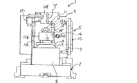
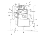
図において、1は5軸横型マシニングセンタ(工作機械)である。このマシニングセンタ1は、平面視長方形状をなすベッド2と、該ベッド2上の、手前側に配設された傾斜テーブル3と、奥側に配設された主軸装置4と、奥側かつ左側部に配置された工具交換装置5と、前記ベッド2の奥側端面に続いて配置された切屑処理装置6と、該処理装置6の後端部に立設された制御装置7とを有する。
In the figure,
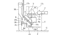
前記傾斜テーブル3は、水平面に対して45°の傾斜支持面8aが形成された側方視で直角三角形をなすベース部材8を有する。このベース部材8は、これの底面に固定されたスライダ8bを前記ベッド2上にZ軸方向に延びるように配設されたZ軸ガイドレール8cにスライド可能に係合させることでZ軸方向に移動可能となっている。
The tilt table 3 has a
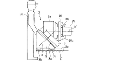
前記ベース部材8の前記傾斜支持面8a上には、旋回台9が該傾斜支持面8aに垂直の旋回軸a回りに旋回可能に配置され、該旋回台9に一体形成されたテーブル支持部9aにはテーブル本体10が前記旋回軸aに対して45°をなす回転軸b回りに回転可能に配設されている。
On the
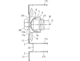
前記テーブル本体10上にワークWが搭載され、固定部材10aにより固定される。前記回転軸bは、前記旋回台9が図4に示す角度位置にあるときには垂直となり、図5に示す角度位置にあるときには水平となる。即ち、前記テーブル本体10は垂直軸b回り及び水平軸b′回りに回転可能となっている。なお、前記テーブル本体10は前記垂直から水平の間の任意の角度で回転可能とすることも可能である。
A workpiece W is mounted on the
ここで前記テーブル本体10のグランド面Gーからの高さHは、オペレータMの腰付近の高さに設定されており、ワークWをテーブル本体10から離脱させるためのストロークhは固定部材10aを越える程度で十分であり、従ってワークWを隣の工作機械に渡す際の搬送高さを低く抑えることができる。また前記ストロークhが小さいのでワーク搬送サイクルタイムを短縮でき、さらに前記ストロークhを確保するための昇降機構も簡単な構造で済み、サイクルタイムの短い安価なワーク搬送を実現できる。
Here, the height H of the
前記主軸装置4は、前記ベッド2上の奥側に立設されたコラム11と、該コラム11の前面に配設された支持プレート12と、該支持プレート12に固定された主軸頭13と、該主軸頭13内に回転可能に配設された主軸14とを有する。
The
前記コラム11は、ベッド2上に固定されてX軸方向に延びるX軸ガイドレール11aにコラム11の底面に固定されたスライダ(図示せず)をスライド可能に係合させることでX軸方向に移動可能となっている。
The
また前記支持プレート12は、前記コラム11の前面に固定されてY軸方向に延びるY軸ガイドレール12aに該支持プレート12に固定されたスライダ12bをスライド可能に係合させ、Y軸送りモータ12cでY軸送りねじ12dを回転駆動することによりY軸方向に移動可能となっている。
The
前記工具交換装置5は、前記ベッド2の、前記主軸装置4より左側方部分に配設され、環状の搬送チェーン15aの周縁に多数の工具Tを備えた工具マガジン15と、該工具マガジン15と前記主軸14との間に配設され、工具マガジン15側の工具と主軸14側の工具とを交換する工具交換アーム16とを備えている。
The
そして前記ベッド2の、前記工具交換装置5が配設された側で、かつ前記傾斜テーブル3の左側方部分には、オペレータMが機械正面から前記工具交換装置5にアクセス可能とするアクセススペースAが形成されている。このアクセススペースAは、ベッド2の一部に形成した切欠き部2aにより構成されている。
An access space A that allows the operator M to access the
なお、17は機体カバーであり、該機体カバー17は前記アクセススペースA及び工具交換装置5を除いて前記傾斜テーブル3及び主軸14の工具側部分を囲んでいる。即ち、前記機体カバー17はオペレータMが工具交換装置5にアクセスする際の障害になることはない。
In addition, 17 is a machine body cover, and this machine body cover 17 surrounds the tool side part of the said inclination table 3 and the main axis |
本実施例1によれば、主軸14をX軸及びY軸方向に移動可能に配設すると共にベッド2の側部に工具交換装置5を配設し、傾斜テーブル3をZ軸方向に移動可能としたので、該傾斜テーブル3のX軸方向側部に障害物のないアクセススペースAを確保でき、オペレータMは該スペースAを利用して機械正面から工具交換装置5にアクセスできる。従って、機械側面から工具交換装置にアクセスする場合に比較して、複数の工作機械1,1を並列配置する場合の間隔Dを狭めることができ、複数の工作機械1,1の設置に必要な設置面積を削減できる。
According to the first embodiment, the
また、前記並列配置された工作機械1,1間でワークを搬送する場合の搬送高さを低く抑えることができ、ワークWをテーブル本体10上に着座・離脱させる際のストロークが短くて済む。そのためワーク搬送のサイクルタイムを短縮できるとともに、昇降機構の構造を簡素化でき、低コストのワーク搬送を実現できる。
In addition, the transfer height when the workpiece is transferred between the
なお、前記実施例1では、傾斜テーブル3がZ軸方向に移動可能に構成されている場合を説明したが、本願請求項1の発明では、傾斜テーブル3はベッド2上に固定されていても良い。このように傾斜テーブル3をベッド2上に固定した場合は、送り機構等を必要としないので、コンパクト化でき、前記アクセススペースAをより一層確実に確保できる。
また、傾斜テーブル3を固定した場合は、前記主軸14は、X軸,Y軸及びZ軸方向に移動可能に構成される。
In the first embodiment, the case where the tilt table 3 is configured to be movable in the Z-axis direction has been described. However, in the invention of
Further, when the tilt table 3 is fixed, the
図6〜図9は本願請求項2の発明の実施例2に係る工作機械を説明するための図であり、図中、図1〜図5と同一符号は同一又は相当部分を示す。
6 to 9 are views for explaining a machine tool according to a second embodiment of the invention of
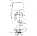
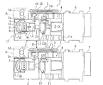
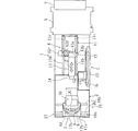
本実施例2では、主軸装置4のコラム11は、ベッド2上の奥側部分に配置固定されたZ軸方向に延びるZ軸ガイドレール11b,11bに該コラムの底面に固定されたスライダ11cをスライド可能に係合させることによりZ軸方向に移動可能となっている。
In the second embodiment, the
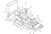
また傾斜テーブル3は、前記ベッド2の手前側部分に、X軸スライド機構19によりX軸方向に移動可能に配設されている。前記X軸スライド機構19は、ベッド2上に配設されたX軸方向に延びる奥側ガイドレール18a及び手前側ガイドレール18bにベース部材8の底面に固定された奥側スライダ18d,手前側スライダ18cをスライド可能に係合させることにより構成されている。
The tilt table 3 is disposed on the front side portion of the
詳細には、前記ベッド2のベース部材8下方部分には、段部2bが他の部分よりY軸方向上側に位置するように形成されており、ベース部材8の段部2bに対応する部分には切欠き部8dが他の部分より高所に位置するように形成されている。前記段部2b上に前記手前側ガイドレール18bが固定され、前記切欠き部8dに前記手前側スライダ18cが固定されている。また前記奥側ガイドレール18aは、前記段部2bに隣接するように配置されている。このようにして前記傾斜テーブル3はX軸方向に移動可能となっている。
Specifically, a
また機体カバー17の前記傾斜テーブル3に対向する部分には、開口17aが形成されており、該開口17aは左,右方向にスライド可能に配設された左,右ドア17b,17bにより開閉可能となっている。
Further, an
さらにまた前記機体カバー17の左,右側面には、インライン搬送用開口17c,17cが形成されている。図示していないが、前記傾斜テーブル3の左,右にはインライン搬送装置が配設される。このインライン搬送装置は、テーブル本体10上のワークWを着座面から離脱する程度に上昇させた状態でX軸方向に搬送し、隣の工作機械に受け渡す搬送装置である。
Furthermore, on the left and right sides of the
この場合、前述したように、前記テーブル本体10が比較的低所に位置しているため、前記インライン搬送装置及び前記開口17cは比較的低所に配設されている。その結果、搬送高さを低く抑えることができると共に、ワークの昇降機構も簡素な構造とすることができる。
In this case, as described above, since the table
本実施例2によれば、傾斜テーブル3をX軸方向に移動可能とするX軸スライド機構19の手前側ガイドレール18bを奥側ガイドレール18aよりY軸方向上側に、つまり高所に配置したので、主軸14によるZ軸方向の切削荷重Fに対して、高所に位置する手前側ガイドレール18bが突っ張ることとなり、切削荷重Fを効率良く負担することができる。従って、切削荷重を負担するための機械構造を、ひいては各工作機械をコンパクトに構成することができ、その結果、複数の工作機械の設置に必要な設置面積を削減できる。
According to the second embodiment, the
また、機体カバー17の左右方向略中央部、つまり傾斜テーブル3に対向する部分に開口17aを設け、該開口17aを左,右開きの左,右ドア17b,17bで開閉するようにしたので、オペレータMは機械正面から傾斜テーブル3上のワークWや主軸14の工具保持部等にアクセスでき、機械側面から作業をする必要がなく、複数の工作機械を並列配置する場合の間隔Dを狭めることができ、必要な設置面積を削減できる。
In addition, since an
図10,図11は本願請求項2の発明の実施例3に係る工作機械を説明するための図であり、図中、図6,7と同一符号は同一又は相当部分を示す。
FIGS. 10 and 11 are views for explaining a machine tool according to a third embodiment of the invention of
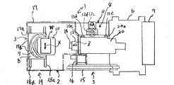
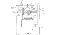
本実施例3では、コラム11はベッド2の奥側かつ側部に移動不能に立設されている。そして該コラム11の右側面に主軸頭支持部材20が配設されており、該主軸頭支持部材20はコラム11に固定されてY軸方向に延びるY軸ガイドレール11d,11dに該主軸頭支持部材20に固定されたスライダ20aをスライド可能に係合させることでY軸方向に移動可能となっている。
In the third embodiment, the
前記主軸頭支持部材20内には主軸頭13がZ軸方向に移動可能に配設されており、該主軸頭13内には主軸14が回転可能に配設されている。
A
また傾斜テーブル3は、ベッド2の段部2bに設けられたX軸スライド機構19によりX軸方向に移動可能となっている。
The tilt table 3 can be moved in the X-axis direction by an
本実施例3においては、コラム11をベッド2上の奥側かつ側部に移動不能に立設したので、コラムを主軸頭の後方に配設した場合に比較して機械の前後長を短縮でき、また傾斜テーブル3の支持構造では前記実施例2と同様の作用効果が得られる。さらに、主軸コラムの一方の側面にY軸移動機構を設けると共に、他方の側面にマガジンを設けることができるので、機械全体の左右方向の横幅寸法を一層コンパクトに構成できる。
In the third embodiment, the
1 5軸横型マシニングセンタ(工作機械)
2 ベッド
3 傾斜テーブル
5 工具交換装置
8 ベース部材
8a 傾斜支持面
9 旋回部材
10 テーブル本体
14 主軸
17 機体カバー
17a 開口
17b ドア
17c インライン搬送用開口
18a 奥側ガイドレール
18b 手前側ガイドレール
19 X軸スライド機構
A アクセススペース
M オペレータ
1 5-axis horizontal machining center (machine tool)
2
Claims (4)
前記ベッド上に軸線方向に移動可能に配設された主軸とを備えた工作機械において、
前記主軸は、機械正面視で、前記ベッド上の奥側に、左右方向(X軸方向),上下方向(Y軸方向)及び主軸軸線方向(Z軸方向)のうち少なくもX軸方向及びY軸方向に移動可能に配設され、
前記傾斜テーブルは、前記ベッド上の手前側に、前記Z軸方向に移動可能に、又は固定して配設され、
前記ベッドの奥側かつ側部に工具交換装置が配設され、
前記ベッドの、前記工具交換装置が配設された側で、かつ前記傾斜テーブルの側方部分に、オペレータが機械正面から前記工具交換装置にアクセス可能とするアクセススペースを設けた
ことを特徴とする工作機械。 A tilting table in which a swivel member is pivotably disposed on an inclined support surface of a base member mounted on the bed, and a table body is rotatably disposed on the swivel member;
In a machine tool comprising a spindle disposed on the bed so as to be movable in the axial direction,
The main shaft is at least one of the left-right direction (X-axis direction), the up-down direction (Y-axis direction), and the main-axis axis direction (Z-axis direction) on the back side of the bed in the machine front view. It is arranged to be movable in the axial direction,
The inclined table is arranged on the front side of the bed so as to be movable or fixed in the Z-axis direction,
A tool changer is disposed on the back side and the side of the bed,
An access space for allowing an operator to access the tool changer from the front of the machine is provided on the side of the bed on the side where the tool changer is disposed and on the side of the inclined table. Machine Tools.
前記ベッド上に軸線方向に移動可能に配設された主軸とを備えた工作機械において、
前記主軸は、機械正面視で、前記ベッド上の奥側に、上下方向(Y軸方向)及び主軸軸線方向(Z軸方向)に移動可能に配設され、
前記傾斜テーブルは、前記ベッド上の手前側に、X軸スライド機構を介して左右方向(X軸方向)に移動可能に配設され、
前記X軸スライド機構は、X軸方向に延び、前記ベッド上の、前記主軸に近い奥側に固定された奥側ガイドレールと、遠い手前側に固定された手前側ガイドレールとを有し、該手前側ガイドレールは、奥側ガイドレールよりY軸方向上側に配置されている
ことを特徴とする工作機械。 A tilting table in which a swivel member is pivotably disposed on an inclined support surface of a base member mounted on the bed, and a table body is rotatably disposed on the swivel member;
In a machine tool comprising a spindle disposed on the bed so as to be movable in the axial direction,
The main shaft is disposed on the back side of the bed in a machine front view so as to be movable in a vertical direction (Y-axis direction) and a main shaft axis direction (Z-axis direction),
The tilt table is disposed on the front side of the bed so as to be movable in the left-right direction (X-axis direction) via an X-axis slide mechanism,
The X-axis slide mechanism has a back guide rail that extends in the X-axis direction and is fixed to the back side near the main shaft on the bed, and a front guide rail fixed to a far front side, The machine tool characterized in that the front guide rail is disposed on the upper side in the Y-axis direction from the back guide rail.
前記傾斜テーブル及び主軸の少なくとも工具側部分を機体カバーで囲むと共に、該機体カバーの左右方向略中央部に開口を設け、該開口を開閉するドアを設けた
ことを特徴とする工作機械。 The machine tool according to claim 2,
A machine tool characterized in that at least a tool side portion of the tilt table and the spindle is surrounded by a machine body cover, an opening is provided in a substantially central portion in the left-right direction of the machine body cover, and a door for opening and closing the opening is provided.
前記機体カバーの左,右側面に、前記テーブル本体上のワークをX軸方向に搬送するインライン搬送用開口を設けた
ことを特徴とする工作機械。 The machine tool according to claim 3,
An in-line transfer opening for transferring a work on the table body in the X-axis direction is provided on the left and right sides of the machine body cover.
Priority Applications (1)
| Application Number | Priority Date | Filing Date | Title |
|---|---|---|---|
| JP2014137255A JP6424028B2 (en) | 2014-07-02 | 2014-07-02 | Machine tool layout |
Applications Claiming Priority (1)
| Application Number | Priority Date | Filing Date | Title |
|---|---|---|---|
| JP2014137255A JP6424028B2 (en) | 2014-07-02 | 2014-07-02 | Machine tool layout |
Publications (2)
| Publication Number | Publication Date |
|---|---|
| JP2016013600A true JP2016013600A (en) | 2016-01-28 |
| JP6424028B2 JP6424028B2 (en) | 2018-11-14 |
Family
ID=55230227
Family Applications (1)
| Application Number | Title | Priority Date | Filing Date |
|---|---|---|---|
| JP2014137255A Active JP6424028B2 (en) | 2014-07-02 | 2014-07-02 | Machine tool layout |
Country Status (1)
| Country | Link |
|---|---|
| JP (1) | JP6424028B2 (en) |
Cited By (3)
| Publication number | Priority date | Publication date | Assignee | Title |
|---|---|---|---|---|
| JP2018001364A (en) * | 2016-07-06 | 2018-01-11 | Dmg森精機株式会社 | Machine tool unit |
| WO2019123657A1 (en) * | 2017-12-22 | 2019-06-27 | 株式会社牧野フライス製作所 | Machine tool |
| CN110434645A (en) * | 2019-07-24 | 2019-11-12 | 中国人民解放军火箭军工程大学 | A kind of five axis hosts for spherical surface cone hole machine |
Citations (17)
| Publication number | Priority date | Publication date | Assignee | Title |
|---|---|---|---|---|
| JPS58171229A (en) * | 1982-03-29 | 1983-10-07 | Yoshiaki Ihara | Structure of table for machining center |
| JPS61265234A (en) * | 1985-05-21 | 1986-11-25 | Murata Mach Ltd | Machine tool |
| JPS62152637A (en) * | 1985-12-26 | 1987-07-07 | Hitachi Seiki Co Ltd | Tool exchanger |
| JPS6397426U (en) * | 1986-12-15 | 1988-06-23 | ||
| JPS63113528U (en) * | 1987-01-16 | 1988-07-21 | ||
| JPH02104946U (en) * | 1989-01-31 | 1990-08-21 | ||
| JPH04118943U (en) * | 1991-04-10 | 1992-10-23 | 村田機械株式会社 | single axis lathe |
| JPH06126585A (en) * | 1992-10-22 | 1994-05-10 | Mekutoron:Kk | Loading device for machine tool |
| JPH0788737A (en) * | 1993-09-21 | 1995-04-04 | Okuma Mach Works Ltd | Five-axis working machine |
| JP2001252837A (en) * | 2000-02-16 | 2001-09-18 | Deckel Maho Pfronten Gmbh | Universal machine tool |
| US20030134731A1 (en) * | 2001-03-21 | 2003-07-17 | Big Alpha Co., Inc. | Automatic-tool-changer-equipped lathe |
| JP2006080409A (en) * | 2004-09-13 | 2006-03-23 | Toshiba Corp | Semiconductor device and manufacturing method thereof |
| US20060189464A1 (en) * | 2003-04-15 | 2006-08-24 | Ioan-Mircea Corbean | Machine tool with tool magazine |
| JP2007160444A (en) * | 2005-12-12 | 2007-06-28 | Nippei Toyama Corp | Machining center |
| JP2008080409A (en) * | 2006-09-25 | 2008-04-10 | Nippei Toyama Corp | Working line of machine tool |
| JP2008105173A (en) * | 2006-09-29 | 2008-05-08 | Nippei Toyama Corp | Machine tool |
| JP5436735B1 (en) * | 2013-09-13 | 2014-03-05 | ヤマザキマザック株式会社 | Vertical machining center |
-
2014
- 2014-07-02 JP JP2014137255A patent/JP6424028B2/en active Active
Patent Citations (17)
| Publication number | Priority date | Publication date | Assignee | Title |
|---|---|---|---|---|
| JPS58171229A (en) * | 1982-03-29 | 1983-10-07 | Yoshiaki Ihara | Structure of table for machining center |
| JPS61265234A (en) * | 1985-05-21 | 1986-11-25 | Murata Mach Ltd | Machine tool |
| JPS62152637A (en) * | 1985-12-26 | 1987-07-07 | Hitachi Seiki Co Ltd | Tool exchanger |
| JPS6397426U (en) * | 1986-12-15 | 1988-06-23 | ||
| JPS63113528U (en) * | 1987-01-16 | 1988-07-21 | ||
| JPH02104946U (en) * | 1989-01-31 | 1990-08-21 | ||
| JPH04118943U (en) * | 1991-04-10 | 1992-10-23 | 村田機械株式会社 | single axis lathe |
| JPH06126585A (en) * | 1992-10-22 | 1994-05-10 | Mekutoron:Kk | Loading device for machine tool |
| JPH0788737A (en) * | 1993-09-21 | 1995-04-04 | Okuma Mach Works Ltd | Five-axis working machine |
| JP2001252837A (en) * | 2000-02-16 | 2001-09-18 | Deckel Maho Pfronten Gmbh | Universal machine tool |
| US20030134731A1 (en) * | 2001-03-21 | 2003-07-17 | Big Alpha Co., Inc. | Automatic-tool-changer-equipped lathe |
| US20060189464A1 (en) * | 2003-04-15 | 2006-08-24 | Ioan-Mircea Corbean | Machine tool with tool magazine |
| JP2006080409A (en) * | 2004-09-13 | 2006-03-23 | Toshiba Corp | Semiconductor device and manufacturing method thereof |
| JP2007160444A (en) * | 2005-12-12 | 2007-06-28 | Nippei Toyama Corp | Machining center |
| JP2008080409A (en) * | 2006-09-25 | 2008-04-10 | Nippei Toyama Corp | Working line of machine tool |
| JP2008105173A (en) * | 2006-09-29 | 2008-05-08 | Nippei Toyama Corp | Machine tool |
| JP5436735B1 (en) * | 2013-09-13 | 2014-03-05 | ヤマザキマザック株式会社 | Vertical machining center |
Cited By (3)
| Publication number | Priority date | Publication date | Assignee | Title |
|---|---|---|---|---|
| JP2018001364A (en) * | 2016-07-06 | 2018-01-11 | Dmg森精機株式会社 | Machine tool unit |
| WO2019123657A1 (en) * | 2017-12-22 | 2019-06-27 | 株式会社牧野フライス製作所 | Machine tool |
| CN110434645A (en) * | 2019-07-24 | 2019-11-12 | 中国人民解放军火箭军工程大学 | A kind of five axis hosts for spherical surface cone hole machine |
Also Published As
| Publication number | Publication date |
|---|---|
| JP6424028B2 (en) | 2018-11-14 |
Similar Documents
| Publication | Publication Date | Title |
|---|---|---|
| KR101878857B1 (en) | Machine tool | |
| US20150117990A1 (en) | Front door-type automatic material-taking device | |
| US9914189B2 (en) | Machine tool having a workpiece changing device | |
| US10207381B2 (en) | Machine tool having a number of multispindle spindle assemblies | |
| JP5033938B2 (en) | Horizontal machine tool | |
| KR20160032136A (en) | Machine tool comprising a swivelable tool spindle | |
| JP6807669B2 (en) | Machine tool unit | |
| JP6424028B2 (en) | Machine tool layout | |
| JP6807192B2 (en) | Machine Tools | |
| JP2016520441A (en) | Machine Tools | |
| JP2010253591A (en) | Compound machining machine and compound machining line | |
| US8864427B2 (en) | Processing machine | |
| TWM541923U (en) | Chain-type transmission mechanism | |
| KR20210004051A (en) | Apparatus for exchanging attachments and horizontal boring machine including the same | |
| JP2009291848A (en) | Machine tool | |
| JP6707408B2 (en) | Machining center | |
| JP2014065132A (en) | Machine tool, and cutting work mechanism for use in the machine tool | |
| JPWO2018146728A1 (en) | Machine Tools | |
| JP6656262B2 (en) | Machining system | |
| JP6811077B2 (en) | Machine tool system | |
| JP2016165774A (en) | Machine tool | |
| JP6637989B2 (en) | Machining system | |
| JP2014065131A (en) | Machine tool system | |
| TWI644758B (en) | Chain drive | |
| JP3174122U (en) | Combined processing machine and combined processing line |
Legal Events
| Date | Code | Title | Description |
|---|---|---|---|
| A621 | Written request for application examination |
Free format text: JAPANESE INTERMEDIATE CODE: A621 Effective date: 20170217 |
|
| A977 | Report on retrieval |
Free format text: JAPANESE INTERMEDIATE CODE: A971007 Effective date: 20171108 |
|
| A131 | Notification of reasons for refusal |
Free format text: JAPANESE INTERMEDIATE CODE: A131 Effective date: 20171114 |
|
| A521 | Request for written amendment filed |
Free format text: JAPANESE INTERMEDIATE CODE: A523 Effective date: 20171225 |
|
| A131 | Notification of reasons for refusal |
Free format text: JAPANESE INTERMEDIATE CODE: A131 Effective date: 20180313 |
|
| A521 | Request for written amendment filed |
Free format text: JAPANESE INTERMEDIATE CODE: A523 Effective date: 20180425 |
|
| TRDD | Decision of grant or rejection written | ||
| A01 | Written decision to grant a patent or to grant a registration (utility model) |
Free format text: JAPANESE INTERMEDIATE CODE: A01 Effective date: 20181002 |
|
| A61 | First payment of annual fees (during grant procedure) |
Free format text: JAPANESE INTERMEDIATE CODE: A61 Effective date: 20181022 |
|
| R150 | Certificate of patent or registration of utility model |
Ref document number: 6424028 Country of ref document: JP Free format text: JAPANESE INTERMEDIATE CODE: R150 |
|
| R250 | Receipt of annual fees |
Free format text: JAPANESE INTERMEDIATE CODE: R250 |