JP2016011237A - Manufacturing method of glass substrate - Google Patents
Manufacturing method of glass substrate Download PDFInfo
- Publication number
- JP2016011237A JP2016011237A JP2014134626A JP2014134626A JP2016011237A JP 2016011237 A JP2016011237 A JP 2016011237A JP 2014134626 A JP2014134626 A JP 2014134626A JP 2014134626 A JP2014134626 A JP 2014134626A JP 2016011237 A JP2016011237 A JP 2016011237A
- Authority
- JP
- Japan
- Prior art keywords
- glass substrate
- glass
- contact
- contact area
- mounting table
- Prior art date
- Legal status (The legal status is an assumption and is not a legal conclusion. Google has not performed a legal analysis and makes no representation as to the accuracy of the status listed.)
- Pending
Links
- 239000011521 glass Substances 0.000 title claims abstract description 200
- 239000000758 substrate Substances 0.000 title claims abstract description 167
- 238000004519 manufacturing process Methods 0.000 title claims abstract description 23
- 238000010438 heat treatment Methods 0.000 claims abstract description 62
- 230000002093 peripheral effect Effects 0.000 claims abstract description 8
- 238000000034 method Methods 0.000 claims description 16
- MCMNRKCIXSYSNV-UHFFFAOYSA-N Zirconium dioxide Chemical compound O=[Zr]=O MCMNRKCIXSYSNV-UHFFFAOYSA-N 0.000 claims description 14
- 238000000137 annealing Methods 0.000 claims description 14
- 229910004298 SiO 2 Inorganic materials 0.000 claims description 9
- 239000000835 fiber Substances 0.000 claims description 8
- 229910052878 cordierite Inorganic materials 0.000 claims description 7
- JSKIRARMQDRGJZ-UHFFFAOYSA-N dimagnesium dioxido-bis[(1-oxido-3-oxo-2,4,6,8,9-pentaoxa-1,3-disila-5,7-dialuminabicyclo[3.3.1]nonan-7-yl)oxy]silane Chemical compound [Mg++].[Mg++].[O-][Si]([O-])(O[Al]1O[Al]2O[Si](=O)O[Si]([O-])(O1)O2)O[Al]1O[Al]2O[Si](=O)O[Si]([O-])(O1)O2 JSKIRARMQDRGJZ-UHFFFAOYSA-N 0.000 claims description 7
- 239000003365 glass fiber Substances 0.000 claims description 5
- 239000004642 Polyimide Substances 0.000 claims description 4
- 229920006231 aramid fiber Polymers 0.000 claims description 4
- 239000011248 coating agent Substances 0.000 claims description 4
- 238000000576 coating method Methods 0.000 claims description 4
- 229920001721 polyimide Polymers 0.000 claims description 4
- 239000006185 dispersion Substances 0.000 abstract description 5
- 238000010030 laminating Methods 0.000 abstract description 3
- 239000000463 material Substances 0.000 description 22
- 239000002585 base Substances 0.000 description 16
- 230000008602 contraction Effects 0.000 description 16
- 239000000919 ceramic Substances 0.000 description 10
- 238000010583 slow cooling Methods 0.000 description 10
- 239000007789 gas Substances 0.000 description 9
- 239000005357 flat glass Substances 0.000 description 7
- 239000000203 mixture Substances 0.000 description 7
- 238000007500 overflow downdraw method Methods 0.000 description 6
- 229910018072 Al 2 O 3 Inorganic materials 0.000 description 4
- 230000000052 comparative effect Effects 0.000 description 4
- 239000002657 fibrous material Substances 0.000 description 4
- 230000007423 decrease Effects 0.000 description 3
- 239000004065 semiconductor Substances 0.000 description 3
- GOLCXWYRSKYTSP-UHFFFAOYSA-N Arsenious Acid Chemical compound O1[As]2O[As]1O2 GOLCXWYRSKYTSP-UHFFFAOYSA-N 0.000 description 2
- OKTJSMMVPCPJKN-UHFFFAOYSA-N Carbon Chemical compound [C] OKTJSMMVPCPJKN-UHFFFAOYSA-N 0.000 description 2
- UQSXHKLRYXJYBZ-UHFFFAOYSA-N Iron oxide Chemical compound [Fe]=O UQSXHKLRYXJYBZ-UHFFFAOYSA-N 0.000 description 2
- 238000006124 Pilkington process Methods 0.000 description 2
- VYPSYNLAJGMNEJ-UHFFFAOYSA-N Silicium dioxide Chemical compound O=[Si]=O VYPSYNLAJGMNEJ-UHFFFAOYSA-N 0.000 description 2
- 238000005520 cutting process Methods 0.000 description 2
- 239000011810 insulating material Substances 0.000 description 2
- 238000009413 insulation Methods 0.000 description 2
- 239000004973 liquid crystal related substance Substances 0.000 description 2
- 229910052751 metal Inorganic materials 0.000 description 2
- 239000002184 metal Substances 0.000 description 2
- 239000006060 molten glass Substances 0.000 description 2
- 230000003287 optical effect Effects 0.000 description 2
- 229910021420 polycrystalline silicon Inorganic materials 0.000 description 2
- 229920005591 polysilicon Polymers 0.000 description 2
- 229910000831 Steel Inorganic materials 0.000 description 1
- 229910000272 alkali metal oxide Inorganic materials 0.000 description 1
- PNEYBMLMFCGWSK-UHFFFAOYSA-N aluminium oxide Inorganic materials [O-2].[O-2].[O-2].[Al+3].[Al+3] PNEYBMLMFCGWSK-UHFFFAOYSA-N 0.000 description 1
- ADCOVFLJGNWWNZ-UHFFFAOYSA-N antimony trioxide Inorganic materials O=[Sb]O[Sb]=O ADCOVFLJGNWWNZ-UHFFFAOYSA-N 0.000 description 1
- QVGXLLKOCUKJST-UHFFFAOYSA-N atomic oxygen Chemical compound [O] QVGXLLKOCUKJST-UHFFFAOYSA-N 0.000 description 1
- 229910052799 carbon Inorganic materials 0.000 description 1
- 210000000078 claw Anatomy 0.000 description 1
- 230000007547 defect Effects 0.000 description 1
- 238000009826 distribution Methods 0.000 description 1
- 238000003280 down draw process Methods 0.000 description 1
- 239000000428 dust Substances 0.000 description 1
- 229910002804 graphite Inorganic materials 0.000 description 1
- 239000010439 graphite Substances 0.000 description 1
- 238000000227 grinding Methods 0.000 description 1
- 238000007689 inspection Methods 0.000 description 1
- 230000001788 irregular Effects 0.000 description 1
- 239000005340 laminated glass Substances 0.000 description 1
- 238000003475 lamination Methods 0.000 description 1
- HTUMBQDCCIXGCV-UHFFFAOYSA-N lead oxide Chemical compound [O-2].[Pb+2] HTUMBQDCCIXGCV-UHFFFAOYSA-N 0.000 description 1
- YEXPOXQUZXUXJW-UHFFFAOYSA-N lead(II) oxide Inorganic materials [Pb]=O YEXPOXQUZXUXJW-UHFFFAOYSA-N 0.000 description 1
- 238000005259 measurement Methods 0.000 description 1
- 150000002739 metals Chemical class 0.000 description 1
- 230000004048 modification Effects 0.000 description 1
- 238000012986 modification Methods 0.000 description 1
- 238000000465 moulding Methods 0.000 description 1
- 229910052760 oxygen Inorganic materials 0.000 description 1
- 239000001301 oxygen Substances 0.000 description 1
- 238000005498 polishing Methods 0.000 description 1
- 238000003672 processing method Methods 0.000 description 1
- 239000002994 raw material Substances 0.000 description 1
- 230000000630 rising effect Effects 0.000 description 1
- 239000000377 silicon dioxide Substances 0.000 description 1
- 239000010959 steel Substances 0.000 description 1
- YEAUATLBSVJFOY-UHFFFAOYSA-N tetraantimony hexaoxide Chemical compound O1[Sb](O2)O[Sb]3O[Sb]1O[Sb]2O3 YEAUATLBSVJFOY-UHFFFAOYSA-N 0.000 description 1
- XOLBLPGZBRYERU-UHFFFAOYSA-N tin dioxide Chemical compound O=[Sn]=O XOLBLPGZBRYERU-UHFFFAOYSA-N 0.000 description 1
- 229910001887 tin oxide Inorganic materials 0.000 description 1
- 238000003466 welding Methods 0.000 description 1
Images

Landscapes
- Re-Forming, After-Treatment, Cutting And Transporting Of Glass Products (AREA)
- Container, Conveyance, Adherence, Positioning, Of Wafer (AREA)
Abstract
Description
本発明は、作製されたガラス基板のアニーリング工程を含むガラス基板の製造方法に関する。 The present invention relates to a method for producing a glass substrate including an annealing step for the produced glass substrate.
近年、ディスプレイパネルの分野では、画質の向上のために画素の高精細化が進展している。この高精細化の進展に伴って、ディスプレイパネルに用いるガラス基板にも寸法精度が高いことが望まれている。例えば、ディスプレイパネルの製造工程中に、ガラス基板が高温で熱処理されても寸法が変化しにくいように、熱収縮の小さいガラス基板が求められている。 In recent years, in the field of display panels, higher definition of pixels has progressed in order to improve image quality. With the progress of this high definition, it is desired that the glass substrate used for the display panel has high dimensional accuracy. For example, a glass substrate having a small thermal shrinkage is required so that the dimensions of the glass substrate are not easily changed during the manufacturing process of the display panel even if the glass substrate is heat-treated at a high temperature.
一般に、ガラス基板の熱収縮率は、ガラスの歪点が高いほど小さくなる。また、ガラス基板の熱収縮率は、ガラス基板の製造工程中の徐冷速度を小さくするほど小さくなることが知られている。しかし、徐冷速度を小さくするとガラス基板の徐冷工程を行う徐冷炉を長くする必要があるが、製造ライン上の徐冷装置を長くすることは困難である。 In general, the thermal shrinkage rate of a glass substrate decreases as the strain point of the glass increases. Moreover, it is known that the thermal shrinkage rate of a glass substrate will become so small that the slow cooling rate in the manufacturing process of a glass substrate is made small. However, if the slow cooling rate is reduced, it is necessary to lengthen the slow cooling furnace that performs the slow cooling process of the glass substrate, but it is difficult to lengthen the slow cooling device on the production line.
そこで、製造ラインで作製された複数のガラス基板に対し、オフラインにおいて時間をかけて熱処理を施すことで、熱収縮率をより低くすることが行われる。例えば、複数のガラス板の間に紙を挟んだ状態で積層した積層体を所定の温度で所要時間保持することで熱収縮率を低減するガラス板の処理方法が知られている(特許文献1)。この方法では、ガラス基板の面内方向外側を断熱材で被覆した状態で積層体を炉内に入れ、面外方向から所定の温度に加熱している。 Therefore, the heat shrinkage rate is further lowered by performing heat treatment on a plurality of glass substrates manufactured on the production line over time. For example, a processing method of a glass plate is known that reduces a thermal shrinkage rate by holding a laminated body in which paper is sandwiched between a plurality of glass plates at a predetermined temperature for a required time (Patent Document 1). In this method, the laminated body is placed in a furnace in a state where the outside in the in-plane direction of the glass substrate is covered with a heat insulating material, and heated to a predetermined temperature from the out-of-plane direction.
複数のガラス板の積層体に対する熱処理をする際、載置台にガラス板とシート体とを交互に載置することで載置台の上で積層体を作成し、積層体を載置台ごと熱処理を行う炉内に搬送し、炉内で積層体および載置台の雰囲気を加熱することで、熱処理を施すことが考えられる。しかし、載置台と雰囲気とで熱伝導率に差異があるため、積層体の外周面であって、載置台に接触する接触領域と、載置台に接触せずに雰囲気と接触する領域とで、熱履歴に差異が生じ、同一の基板内で熱収縮率にばらつきが生じるという問題がある。 When heat-treating a laminated body of a plurality of glass plates, a laminated body is created on the placing table by alternately placing glass plates and sheet bodies on the placing table, and the laminated body is subjected to heat treatment together with the placing table. It can be considered that heat treatment is performed by transporting into the furnace and heating the atmosphere of the laminate and the mounting table in the furnace. However, because there is a difference in the thermal conductivity between the mounting table and the atmosphere, the outer peripheral surface of the laminate, the contact area that contacts the mounting table, and the area that contacts the atmosphere without contacting the mounting table, There is a problem that a difference occurs in the heat history, and the heat shrinkage rate varies within the same substrate.
そこで、本発明は、複数のガラス板の積層体に対する熱処理の際に、同一のガラス基板内の熱収縮率のばらつきを低減することができるガラス基板の製造方法を提供することを目的とする。 Therefore, an object of the present invention is to provide a method for manufacturing a glass substrate that can reduce variation in the thermal shrinkage rate in the same glass substrate when heat-treating a laminated body of a plurality of glass plates.
本発明の一態様は、作製されたガラス基板のアニーリング工程を含むガラス基板の製造方法である。
前記アニーリング工程は、複数のガラス基板をそれぞれシート体の間に挟んだ状態で厚さ方向に積層したガラス基板の積層体を載置台に載置する工程と、前記積層体を前記ガラス基板の面内方向外側から加熱することで、前記複数のガラス基板の熱収縮率を低下させる熱処理工程と、を含む。
前記熱処理工程において、前記積層体の外周面であって、前記載置台に接触する接触領域と、前記載置台に接触しない非接触領域との熱履歴が等しくなるように調整する。
One embodiment of the present invention is a method for manufacturing a glass substrate including an annealing step of the manufactured glass substrate.
The annealing step includes a step of placing a laminated body of glass substrates, each of which is laminated in a thickness direction with a plurality of glass substrates sandwiched between sheet bodies, on a placing table, and placing the laminated body on the surface of the glass substrate. A heat treatment step of reducing the thermal shrinkage rate of the plurality of glass substrates by heating from the outside in the inner direction.
In the heat treatment step, adjustment is made so that the thermal history of the contact area that is in contact with the mounting table and the non-contact area that is not in contact with the mounting table is equal to the outer peripheral surface of the stacked body.
ここで、熱履歴が等しいとは、室温から熱処理の最高温度までの温度上昇速度、最高温度に維持される時間、最高温度から室温までの温度低下速度が等しいことをいう。ここで「等しい」とは、一方と他方の比が0.9〜1.1の範囲内であることをいう。 Here, that the thermal histories are equal means that the temperature increase rate from the room temperature to the maximum temperature of the heat treatment, the time for maintaining the maximum temperature, and the temperature decrease rate from the maximum temperature to the room temperature are equal. Here, “equal” means that the ratio of one to the other is in the range of 0.9 to 1.1.
前記熱処理工程において、例えば、前記積層体および前記載置台の周囲の気体を加熱することで前記積層体を前記ガラス基板の面内方向外側から加熱する。そこで、前記載置台の前記接触領域と接触する接触部の熱伝導率を、積層体および載置台の周囲の気体の熱伝導率に近い値に調整することが好ましい。
例えば、前記載置台の前記接触領域と接触する接触部の熱伝導率は、5W/m・K以下であることが好ましい。
In the heat treatment step, for example, the laminate is heated from the outside in the in-plane direction of the glass substrate by heating the gas around the laminate and the mounting table. Then, it is preferable to adjust the thermal conductivity of the contact part which contacts the said contact area | region of the said mounting base to the value close | similar to the thermal conductivity of the gas around a laminated body and a mounting base.
For example, it is preferable that the thermal conductivity of the contact portion in contact with the contact area of the mounting table is 5 W / m · K or less.
また、接触部の材料には、積層体および載置台の周囲の気体を多く含むように、空洞率の高い材料を用いることが好ましい。このような材料として、繊維材料やセラミックスを接触部に用いることができる。
例えば、前記載置台の前記接触領域と接触する接触部は、ガラス繊維、ポリイミド繊維、アラミド繊維等の繊維材料、ステアタイト(MgO・SiO2)、ジルコニア(ZrO2)、コージライト(2MgO・2AlO3・5SiO2)等のセラミックスから選ばれた一種、又は、それらの組合せからなることが好ましい。
ステアタイト、ジルコニア、コージライト等のセラミックスを接触部に用いる場合、接触領域との接触面に凹凸形状を設け、接触領域と接触部との間に隙間が空くようにすることで、接触領域が積層体および載置台の周囲の気体と接触するため、接触領域と非接触領域との熱履歴をほぼ等しくすることができる。
In addition, it is preferable to use a material having a high cavity ratio so that the contact portion material contains a large amount of gas around the laminate and the mounting table. As such a material, a fiber material or ceramics can be used for the contact portion.
For example, the contact portion that comes into contact with the contact region of the mounting table includes fiber materials such as glass fiber, polyimide fiber, and aramid fiber, steatite (MgO · SiO 2 ), zirconia (ZrO 2 ), cordierite (2MgO · 2AlO). 3 · 5SiO 2) one selected from ceramics and the like, or preferably consists of a combination thereof.
When using ceramics such as steatite, zirconia, cordierite, etc. for the contact area, the contact area is provided with an irregular shape on the contact surface so that there is a gap between the contact area and the contact area. Since it contacts with the gas around the laminate and the mounting table, the thermal history of the contact area and the non-contact area can be made substantially equal.
前記載置台の前記接触領域と接触する接触部の耐熱温度は、550℃以上であることが好ましい。
切り出したガラス基板を550℃以下の温度(例えば400℃〜550℃)で加熱することで、ガラス基板中の結晶化度が高まり、ガラス基板の体積が小さくなる。この熱処理工程を行ったガラス基板では、以後の処理において再びガラス基板を加熱した場合でも、結晶化度が高まることでガラス基板の体積が小さくなる現象(熱収縮)が生じにくくなる。
接触部の耐熱温度を550℃以上とすることで、この熱処理工程において接触部が変形・変質しないでその機能を保つことができる。
It is preferable that the heat-resistant temperature of the contact part which contacts the said contact area | region of the said mounting base is 550 degreeC or more.
By heating the cut glass substrate at a temperature of 550 ° C. or lower (for example, 400 ° C. to 550 ° C.), the crystallinity in the glass substrate is increased and the volume of the glass substrate is reduced. In the glass substrate subjected to this heat treatment step, even when the glass substrate is heated again in the subsequent processing, a phenomenon (thermal shrinkage) in which the volume of the glass substrate decreases due to an increase in crystallinity is less likely to occur.
By setting the heat resistant temperature of the contact portion to 550 ° C. or more, the function of the contact portion can be maintained without being deformed or altered in this heat treatment step.
前記熱処理工程において、前記接触部と熱伝導率が等しい被覆部材で前記非接触領域を被覆することが好ましい。ここで「等しい」とは、一方と他方の比が0.9〜1.1の範囲内であることをいう。これにより、接触領域と非接触領域との熱履歴を等しくすることができる。 In the heat treatment step, the non-contact region is preferably covered with a covering member having the same thermal conductivity as that of the contact portion. Here, “equal” means that the ratio of one to the other is in the range of 0.9 to 1.1. Thereby, the thermal history of a contact area | region and a non-contact area | region can be made equal.
上述のガラス基板の製造方法によれば、複数のガラス板の積層体に対する熱処理の際に、積層体の外周面であって、載置台に接触する接触領域と、載置台に接触しない非接触領域との熱履歴の差異を低減することができるので、同一のガラス基板内の熱収縮率のばらつきを低減することができる。 According to the above-described method for manufacturing a glass substrate, when heat treatment is performed on a laminated body of a plurality of glass plates, the outer peripheral surface of the laminated body is a contact area that is in contact with the mounting table and a non-contact area that is not in contact with the mounting table. The difference in thermal history between the glass substrate and the thermal shrinkage rate in the same glass substrate can be reduced.
以下、本発明のガラス基板の製造方法について詳細に説明する。
〔第1実施形態〕
図1は、本実施形態のガラス板の製造方法の流れを示すフローチャートである。製造されるガラス基板は、特に制限されないが、例えば縦寸法及び横寸法のそれぞれが500mm〜3500mmであることが好ましい。ガラス基板の厚さは、0.1〜1.1(mm)の極めて薄い矩形形状の板であることが好ましい。
まず、熔融されたガラスが、例えばフュージョン法あるいはフロート法等の公知の方法により、所定の厚さの帯状ガラスであるシートガラスを成形する(ステップS1)。
Hereinafter, the manufacturing method of the glass substrate of this invention is demonstrated in detail.
[First Embodiment]
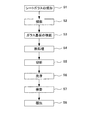
FIG. 1 is a flowchart showing the flow of the glass plate manufacturing method of the present embodiment. Although the glass substrate manufactured is not specifically limited, For example, it is preferable that each of the vertical dimension and the horizontal dimension is 500 mm to 3500 mm. The glass substrate is preferably an extremely thin rectangular plate having a thickness of 0.1 to 1.1 (mm).
First, the melted glass is formed into a sheet glass which is a strip glass having a predetermined thickness by a known method such as a fusion method or a float method (step S1).
なお、シートガラスの成形後、シートガラスをその歪点よりも高く、かつ、徐冷点よりも低い温度で徐冷炉において徐冷する徐冷工程を含むことが好ましい。徐冷工程を行うことにより、シートガラスの内部歪および反りを低減することができる。 In addition, it is preferable to include a slow cooling step in which the sheet glass is gradually cooled in a slow cooling furnace at a temperature higher than the strain point and lower than the annealing point after the sheet glass is formed. By performing the slow cooling step, internal strain and warpage of the sheet glass can be reduced.
次に、成形されたシートガラスを所定の長さの素板であるガラス基板に採板する(ステップS2)。採板により得られたガラス基板は、ガラス基板を保護するシート体と交互に積層してガラス基板の積層体を作製する(ステップS3)。次に、このガラス基板の積層体に対して熱処理を行なう(ステップS4)。このステップS3の処理およびステップS4の処理が本実施形態のアニーリング工程である。アニーリング工程の詳細については後述する。 Next, the formed sheet glass is sampled on a glass substrate which is a base plate having a predetermined length (step S2). The glass substrate obtained by the plate-making is laminated alternately with a sheet body that protects the glass substrate to produce a laminated body of glass substrates (step S3). Next, heat treatment is performed on the laminated body of glass substrates (step S4). The process of step S3 and the process of step S4 are the annealing process of this embodiment. Details of the annealing step will be described later.
熱処理後のガラス基板は切断工程に搬送され、製品のサイズに切断され、ガラス基板が得られる(ステップS5)。得られたガラス基板には、端面の研削、研磨およびコーナカットを含む端面加工が行われた後、ガラス基板は洗浄される(ステップS6)。洗浄されたガラス基板はキズ、塵、汚れあるいは光学欠陥を含む傷が無いか、光学的検査が行われる(ステップS7)。検査により品質の適合したガラス基板は、ガラス基板を保護する紙と交互に積層された積層体としてパレットに積載されて梱包される(ステップS8)。梱包されたガラス基板は納入先業者に出荷される。 The glass substrate after the heat treatment is conveyed to a cutting process, and is cut into a product size to obtain a glass substrate (step S5). The obtained glass substrate is subjected to end face processing including end face grinding, polishing and corner cutting, and then the glass substrate is washed (step S6). The cleaned glass substrate is optically inspected for scratches, dust, dirt, or scratches including optical defects (step S7). A glass substrate having a quality suitable by inspection is loaded on a pallet and packed as a laminated body alternately laminated with paper protecting the glass substrate (step S8). The packed glass substrate is shipped to a supplier.
本実施形態で製造されるガラス基板は、ディスプレイパネルに用いるガラス基板、例えば、液晶ディスプレイ用ガラス基板あるいは、有機ELディスプレイ用のガラス基板として好適である。さらに、本実施形態で製造されるガラス基板は、高精細ディスプレイに用いるLTPS(Low-temperature poly silicon)・TFTディスプレイ用ガラス基板、あるいは、酸化物半導体・TFTディスプレイ用のガラス基板として特に好適である。 The glass substrate manufactured in this embodiment is suitable as a glass substrate used for a display panel, for example, a glass substrate for liquid crystal display or a glass substrate for organic EL display. Furthermore, the glass substrate manufactured in this embodiment is particularly suitable as a glass substrate for LTPS (Low-temperature poly silicon) TFT display used for high-definition displays, or a glass substrate for oxide semiconductor TFT displays. .
本実施形態のガラス基板は、熱収縮率は10ppm以下であることが、高精細なディスプレイパネル用のガラス基板に用いられる点から好ましく、熱収縮率は6ppm以下であることがより好ましい。ガラス基板の歪は、9 kgf/cm2以下であることが反りを発生させず、歪による光学特性の変化、例えば屈折率の変化を抑える点から好ましく、4 kgf/cm2以下であることがより好ましい。歪の下限は特に制限されないが、実質的には2 kgf/cm2である。
ガラス基板の歪点は、高精細ディスプレイ用ガラス基板とするために、600℃〜760℃であることが好ましく、655℃以上であることがより一層好ましい。例えば、歪点は、661℃である。
The glass substrate of this embodiment preferably has a heat shrinkage rate of 10 ppm or less from the viewpoint of being used for a glass substrate for a high-definition display panel, and more preferably has a heat shrinkage rate of 6 ppm or less. The distortion of the glass substrate is preferably 9 kgf / cm 2 or less from the viewpoint of suppressing the change in optical characteristics due to the distortion, for example, the change in refractive index, without causing warpage, and is 4 kgf / cm 2 or less. More preferred. The lower limit of the strain is not particularly limited, but is substantially 2 kgf / cm 2 .
The strain point of the glass substrate is preferably 600 ° C. to 760 ° C., and more preferably 655 ° C. or higher in order to obtain a glass substrate for a high-definition display. For example, the strain point is 661 ° C.
このようなガラス基板として、以下のガラス組成のガラス基板が例示される。つまり、以下のガラス組成のガラス基板が製造されるように、熔融ガラスの原料が調合される。
SiO2 55〜80モル%、
Al2O3 8〜20モル%、
B2O3 0〜12モル%、
RO 0〜17モル%(ROはMgO、CaO、SrO及びBaOの合量)。
As such a glass substrate, the glass substrate of the following glass compositions is illustrated. That is, the raw material of molten glass is prepared so that the glass substrate of the following glass compositions is manufactured.
SiO 2 55~80 mol%,
Al 2 O 3 8-20 mol%,
B 2 O 3 0 to 12 mol%,
RO 0 to 17 mol% (RO is the total amount of MgO, CaO, SrO and BaO).
SiO2は60〜75モル%、さらには、63〜72モル%であることが、熱収縮率を小さくするという観点から好ましい。
ROのうち、MgOが0〜10モル%、CaOが0〜10モル%、SrOが0〜10%、BaOが0〜10%であることが好ましい。
SiO 2 is preferably 60 to 75 mol%, and more preferably 63 to 72 mol%, from the viewpoint of reducing the heat shrinkage rate.
Among RO, it is preferable that MgO is 0-10 mol%, CaO is 0-10 mol%, SrO is 0-10%, and BaO is 0-10%.
また、SiO2、Al2O3、B2O3、及びROを少なくとも含み、モル比((2×SiO2)+Al2O3)/((2×B2O3)+RO)は4.5以上であるガラスであってもよい。また、MgO、CaO、SrO、及びBaOの少なくともいずれか含み、モル比(BaO+SrO)/ROは0.1以上であることが好ましい。 Further, at least SiO 2 , Al 2 O 3 , B 2 O 3 , and RO are included, and the molar ratio ((2 × SiO 2 ) + Al 2 O 3 ) / ((2 × B 2 O 3 ) + RO) is 4. The glass which is 5 or more may be sufficient. In addition, it is preferable that at least one of MgO, CaO, SrO, and BaO is included, and the molar ratio (BaO + SrO) / RO is 0.1 or more.
また、モル%表示のB2O3の含有率の2倍とモル%表示のROの含有率の合計は、30モル%以下、好ましくは10〜30モル%であることが好ましい。
また、上記ガラス組成のガラス基板におけるアルカリ金属酸化物の含有率は、0モル%以上0.4モル%以下であってもよい。
また、ガラス中で価数変動する金属の酸化物(酸化スズ、酸化鉄)を合計で0.05〜1.5モル%含み、As2O3、Sb2O3及びPbOを実質的に含まないということは必須ではなく任意である。
The total content of 2-fold and mol% of RO for the content of mol% of B 2 O 3 is 30 mol% or less, it is preferred that preferably 10 to 30 mol%.
Moreover, 0 mol% or more and 0.4 mol% or less may be sufficient as the content rate of the alkali metal oxide in the glass substrate of the said glass composition.
In addition, it is essential that 0.05 to 1.5 mol% of oxides of metals (tin oxide and iron oxide) whose valence fluctuates in glass are included and that As2O3, Sb2O3 and PbO are not substantially contained. It is optional.
〔アニーリング工程〕
次に、アニーリング工程について詳細に説明する。まず、ステップS2で採板された複数のガラス基板11と複数のシート体12とを交互に1枚ずつ積層してガラス基板の積層体10を作製する(ステップS3)。
[Annealing process]
Next, the annealing process will be described in detail. First, a plurality of
図2は、本実施形態に係るガラス基板の積層体10(以下、積層体10という)が載置される載置台20を示す側面図である。ここで、図2の左側を載置台20の前側、図2の右側を載置台20の後側とする。載置台20には、積層体10が積層方向をほぼ前後方向として載置される。ここで、積層体10の積層方向は前後方向と完全に一致している必要はない。例えば、図2に示すように、ガラス基板11を斜めに立てかける場合、積層方向と前後方向とのなす角はガラス基板11の上下方向とのなす角となる。
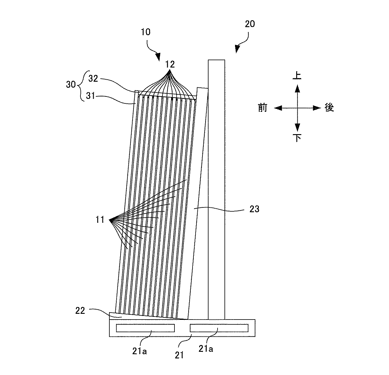
FIG. 2 is a side view showing the mounting table 20 on which the glass substrate laminate 10 (hereinafter referred to as the laminate 10) according to the present embodiment is placed. Here, the left side of FIG. 2 is the front side of the mounting table 20, and the right side of FIG. The
積層体10は、複数のガラス基板11と、複数のシート体12と、を有する。
シート体12は、ガラス基板11同士の間に挟まれる。シート体12は積層されるガラス基板11同士の密着を防ぐ役割を果たす。シート体12には、積層体10を熱処理する際の温度に耐えうる耐熱性を有する材料を用いることができる。シート体12は、ガラス基板11よりも高い熱伝導率を有することが好ましい。
このようなシート体12の材料として、例えば、カーボングラファイト、アルミナ繊維、シリカ繊維、ガラス繊維、及び、多孔質セラミックスから選ばれた一種、又は、それらの組合せを選択することができる。
The
The
As a material of such a
シート体12の厚さは、ガラス基板11の面内方向の熱伝導率を高めるために厚いことが好ましい。一方、積層体10の体積を低減するためにシート体12の厚さは薄いことが好ましい。このため、シート体12の厚さは、0.02mm〜3mm程度であることが好ましい。シート体12の面積は、ガラス基板11同士の密着を防ぐ役割から、ガラス基板11と同程度またはそれ以上であることが好ましい。
The thickness of the
載置台20は、基台部21と、載置部22と、等を備える。載置部22および背面板23は、積層体10と接触する接触部である。
基台部21は、例えば鋼鉄等の金属からなり、溶接等により一体に形成されている。
基台21は略長方形の板状であり、端面にフォークリフトの爪を挿入するための開口21aが設けられている。
載置部22は基台21の上部に固定されており、載置部22の上部にガラス基板の積層体10が載せられる。ここで、載置部22の上面は完全に水平である必要はない。例えば、図2に示すように、ガラス基板11を斜めに立てかける場合、ガラス基板11の立てかけ角度に応じて載置部22の上面を傾斜させておいてもよい。
The mounting table 20 includes a
The
The
The mounting
載置台20は、図2に示すように、ガラス基板11を立てかけるための背面板23を備えてもよい。背面板23は略長方形の板状であり、基台21の上部において、載置部22の後端に載置部22とほぼ垂直に固定されている。背面板23は載置部22の上部に載せられる積層体10の積層方向の後端部を支持する。ここで、背面板23は完全に鉛直である必要はない。例えば、図2に示すように、ガラス基板11を斜めに立てかける場合、ガラス基板11の立てかけ角度に応じて背面板23を傾斜させておいてもよい。
As shown in FIG. 2, the mounting table 20 may include a
積層体10は載置台20に載置された状態で熱処理を行う炉に搬入される。炉内では、積層体10および載置台20は炉内の空気(積層体10および載置台20の雰囲気)が加熱されることにより加熱される。この間、載置部22および背面板23は、積層体10に接触した状態にある。なお、図2において、積層体10の下面が載置部22に接触する接触領域であり、積層体10の後面が背面板23に接触する接触領域である。積層体10のその他の面(前面、上面、および左右両側面)は非接触領域である。
このため、炉内の空気の熱伝導率が載置台20の熱伝導率と異なると、積層体10の外周面であって、載置台20に接触する接触領域と、載置台20に接触せずに炉内の空気に接触する非接触領域とで熱履歴に差異が生じる。
そこで、本実施形態においては、接触領域と非接触領域との熱履歴が等しくなるように調整する。
The
For this reason, when the thermal conductivity of the air in the furnace is different from the thermal conductivity of the mounting table 20, it is the outer peripheral surface of the
Therefore, in the present embodiment, adjustment is made so that the thermal histories of the contact area and the non-contact area are equal.
具体的には、載置台20の接触領域(載置部22および背面板23)と接触する接触部の熱伝導率を、積層体10および載置台20の周囲の気体の熱伝導率に近い値に調整することが好ましい。
例えば、載置部22および背面板23の熱伝導率は、5W/m・K以下であることが好ましい。
Specifically, the thermal conductivity of the contact portion that comes into contact with the contact area (the mounting
For example, the thermal conductivity of the mounting
また、載置部22および背面板23の材料には、積層体10および載置台20の周囲の気体を多く含むように、空洞率の高い材料を用いることが好ましい。このような材料として、繊維系断熱材やセラミックスを接触部に用いることができる。
例えば、載置部22および背面板23は、ガラス繊維(熱伝導率0.55〜0.75W/m・K)、ポリイミド繊維(熱伝導率0.28〜0.34W/m・K)、アラミド繊維(熱伝導率0.05W/m・K)等の繊維系断熱材、または、ステアタイト(MgO・SiO2、熱伝導率2W/m・K)、ジルコニア(ZrO2、熱伝導率3W/m・K)、コージライト(2MgO・2AlO3・5SiO2、熱伝導率4W/m・K)等のセラミックス(いずれも熱伝導率は2〜4W/m・K)から選ばれた一種、又は、それらの組合せからなることが好ましい。
ステアタイト、ジルコニア、コージライト等のセラミックスを載置部22又は背面板23に用いる場合、載置部22又は背面板23の接触領域との接触面に凹凸形状を設け、接触領域と載置部22又は背面板23との間に隙間が空くようにすることで、接触領域が積層体10および載置台20の周囲の気体と接触するため、接触領域と非接触領域との熱履歴をほぼ等しくすることができる。
載置部22および背面板23は同一の材質であってもよいし、異なる材質であってもよい。
Moreover, it is preferable to use a material with a high cavity ratio so that the material of the mounting
For example, the mounting
When ceramics such as steatite, zirconia, cordierite, etc. are used for the mounting
The mounting
載置部22および背面板23の耐熱温度は、550℃以上であることが好ましい。
切り出したガラス基板を歪点以下の温度、具体的には550℃以下の温度(例えば400℃〜550℃)で加熱することで、ガラス基板中の原子配列の結晶化度が高まり、ガラス基板の体積が小さくなる。この熱処理工程を行ったガラス基板では、原子配列の結晶化度が既に高められているため、以後の処理において再びガラス基板を加熱した場合でも、さらにガラス基板の体積が小さくなる現象(熱収縮)が生じにくくなる。なお、550℃よりも高い温度にガラス基板を加熱すると、徐冷工程においてある程度高まったガラスの結晶化度が再び低下するため、550℃以下の温度で熱処理を行うことが好ましい。また、LTPS、IGZOから構成される半導体層をガラス基板11に形成する温度は、400℃〜550℃であるため、この温度範囲である400〜550℃で熱処理を行うことにより、この温度領域における熱収縮率を低減させることができる。
載置部22の耐熱温度を550℃以上とすることで、この熱処理工程において接触部が変形・変質しないでその機能を保つことができる。
The heat resistance temperature of the mounting
By heating the cut glass substrate at a temperature below the strain point, specifically at a temperature of 550 ° C. or lower (for example, 400 ° C. to 550 ° C.), the crystallinity of the atomic arrangement in the glass substrate is increased. The volume becomes smaller. In the glass substrate subjected to this heat treatment step, the crystallinity of the atomic arrangement has already been increased. Therefore, even when the glass substrate is heated again in the subsequent processing, the phenomenon that the volume of the glass substrate is further reduced (thermal contraction). Is less likely to occur. Note that when the glass substrate is heated to a temperature higher than 550 ° C., the degree of crystallinity of the glass, which has been increased to some extent in the slow cooling step, is reduced again, and it is preferable to perform heat treatment at a temperature of 550 ° C. or lower. Moreover, since the temperature which forms the semiconductor layer comprised from LTPS and IGZO in the
By setting the heat resistant temperature of the mounting
次に、ステップS4の熱処理について説明する。
ステップS3の処理で作製された積層体10に対して、製造ラインから外れたオフラインで熱処理が行われる(ステップS4)。この熱処理では、ガラス基板の積層体を所定の温度の雰囲気下に所定時間放置することで、積層体10をガラス基板11の面内方向外側から加熱することで、複数のガラス基板11の熱収縮率を低下させる。
Next, the heat treatment in step S4 will be described.
The
具体的には、熱処理を行う炉に上記の積層体10が載せられた載置台20を搬入し、炉内の空気を加熱して所定時間放置することによりガラス基板11を面内方向外側から加熱する。積層体10をガラス基板11の面内方向外側から加熱することで、複数のガラス基板11間の熱分布を一様にすることができる。したがって、熱処理後の各ガラス基板11の熱収縮率のばらつきを低減することができる。
Specifically, the
また、熱処理を行う炉に上記の積層体10が載せられた載置台20を搬入し、炉内の空気を加熱して所定時間放置することにより積層体10の6面すべてを加熱する。積層体10の厚さが、例えば500mm以下である場合、積層体10の厚さ方向の両端に位置するガラス基板11面から、積層体10の厚さ方向の中央にあるガラス基板11に向かって熱がすぐに伝わる。積層体10の周囲の熱伝導率の差を抑制し、積層体10の周囲を均一に加熱することにより、積層体10の厚さが500mm以下である場合には、積層体10の厚さ方向の両端に位置するガラス基板11と、両端のガラス基板11に挟まれた中央に位置するガラス基板11との熱履歴の差異を低減することができる。
In addition, the mounting table 20 on which the laminate 10 is placed is loaded into a furnace for heat treatment, and the air in the furnace is heated and left for a predetermined time to heat all six surfaces of the laminate 10. When the thickness of the
熱処理の温度は、400℃〜550℃の温度範囲であることが、熱収縮率を低減させる点から好ましい。特に、シートガラスの成形後、徐冷を行うことによりガラス基板の内部歪を除去している場合、ガラスの結晶化度がある程度高まっているため、400℃〜550℃の温度範囲で熱処理を行うことで、内部歪が除去された状態を維持しながらガラスの結晶化度をさらに高め、ガラスの体積を小さくし、熱処理後のガラス基板の熱収縮率を低減することができる。
熱処理の時間は、例えば室温から400℃〜550℃の温度範囲まで加熱するのに1〜20時間、400℃〜550℃の温度範囲を維持する時間が1〜120時間、400℃〜550℃の温度範囲から室温まで冷却するのに4〜80時間である。400℃〜550℃の温度範囲を維持する時間が1時間未満であると、熱収縮率が十分に低下せず、120時間より長いと、熱収縮率は十分低減するが、ガラス基板11の生産効率が低下する。
なお、歪点はガラスの種類によって異なるが、ガラス基板11は、熱収縮を小さくするために、歪点が高いガラス組成を有することが好ましく、例えばガラス基板11のガラスの歪点は、600℃〜760℃であることが好ましく、655℃以上であることがより一層好ましい。例えば、歪点は、661℃である。歪点が低いガラス基板であっても、熱処理することにより、歪点が高いガラス基板と同程度の熱収縮率を実現することができる。この場合、熱処理温度の最低温度は、200℃(=600℃―400℃)以上である。
ガラス基板の積層体が晒される高温の雰囲気は、特に制限されず、酸素含率が5〜50%である雰囲気であってもよく、例えば空気からなる大気雰囲気であってもよい。
The temperature of the heat treatment is preferably in the temperature range of 400 ° C. to 550 ° C. from the viewpoint of reducing the heat shrinkage rate. In particular, when the internal distortion of the glass substrate is removed by annealing after forming the sheet glass, the crystallinity of the glass is increased to some extent, so heat treatment is performed in the temperature range of 400 ° C to 550 ° C. Thus, it is possible to further increase the crystallinity of the glass while maintaining the state in which the internal strain is removed, to reduce the volume of the glass, and to reduce the thermal contraction rate of the glass substrate after the heat treatment.
The heat treatment time is, for example, 1 to 20 hours for heating from room temperature to a temperature range of 400 ° C to 550 ° C, 1 to 120 hours for maintaining the temperature range of 400 ° C to 550 ° C, and 400 ° C to 550 ° C. It takes 4 to 80 hours to cool from the temperature range to room temperature. When the time for maintaining the temperature range of 400 ° C. to 550 ° C. is less than 1 hour, the heat shrinkage rate is not sufficiently lowered. When the time is longer than 120 hours, the heat shrinkage rate is sufficiently reduced, but the production of the
Although the strain point varies depending on the type of glass, the
The high temperature atmosphere to which the laminate of the glass substrate is exposed is not particularly limited, and may be an atmosphere having an oxygen content of 5 to 50%, for example, an air atmosphere composed of air.
このような熱処理により、ガラス基板11の熱収縮率を0〜12ppmとすることができる。ガラス基板11の熱収縮率は、0〜6ppmとすることが好ましく、0〜3ppmとすることがより好ましい。このような熱収縮率が、ガラス基板のガラス組成と、熱処理の温度と熱処理時間を調整することにより達成することができる。
By such heat treatment, the thermal shrinkage rate of the
本実施形態では、熱処理工程において、積層体10の外周面であって、載置台20に接触する接触領域と、載置台20に接触しない非接触領域との熱履歴が等しくなるように調整することで、接触領域と非接触領域との熱履歴の差異を低減することができる。このため、ガラス基板11内の熱収縮率のばらつきを低減することができる。
In the present embodiment, in the heat treatment step, adjustment is performed so that the thermal history of the contact area that is in contact with the mounting table 20 and the non-contact area that is not in contact with the mounting table 20 is equal to the outer peripheral surface of the stacked
なお、積層体10をガラス基板11の面内方向外側から加熱するために、積層体10の積層方向の両端部(図2の前面側および後面側)に1対の断熱板15a、15bを配置し、1対の断熱板15a、15bで積層体10を積層方向に挟んだ状態で熱処理を行ってもよい。この場合においても、載置台20に接触する接触領域(図2の下面)と、非接触領域のうち断熱板15a、15bにより被覆される領域(図2の前面および後面)を除く領域(図2の上面および左右両側面)との熱履歴が等しくなるように調整し、熱履歴の差異を低減することができる。このため、ガラス基板11内の熱収縮率のばらつきを低減することができる。
In addition, in order to heat the
〔第2実施形態〕
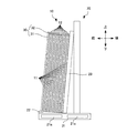
図3は第2実施形態に係るガラス基板の積層体10が載置される載置台20を示す側面図である。第2実施形態では、積層体10の載置台20との非接触領域が、載置台20の接触部と熱伝導率が等しい被覆部材30(被覆部材31、32を含む)で被覆されている点が、第1実施形態と異なる。ここで、積層体10の下面が載置部22に接触する接触領域であり、積層体10の後面が背面板23に接触する接触領域である。積層体10のその他の面(前面、上面、および左右両側面)は非接触領域である。
[Second Embodiment]
FIG. 3 is a side view showing the mounting table 20 on which the
被覆部材30は、積層体10の非接触領域(前面、上面、および左右両側面)を被覆するように設けられている。なお、図3では、積層体10の前面を被覆部材31が覆っており、積層体10の上面を被覆部材32が覆っているが、積層体10の図示されない左右両側面もまた、同様の被覆部材により被覆されている。
被覆部材30には、載置台20の載置部22および背面板23と同程度の熱伝導率を有する材料が用いられる。被覆部材30の熱伝導率は、5W/m・K以下であることが好ましい。
The covering
For the covering
また、被覆部材30の材料には、積層体10および載置台20の周囲の気体を多く含むように、空洞率の高い材料を用いることが好ましい。このような材料として、繊維材料やセラミックスを接触部に用いることができる。
In addition, it is preferable to use a material having a high cavity ratio so that the covering
例えば、被覆部材30は、ガラス繊維、ポリイミド繊維、アラミド繊維等の繊維材料、ステアタイト(MgO・SiO2)、ジルコニア(ZrO2)、コージライト(2MgO・2AlO3・5SiO2)等のセラミックスから選ばれた一種、又は、それらの組合せからなることが好ましい。
For example, the covering
ステアタイト、ジルコニア、コージライト等のセラミックスを載置台20の載置部22および背面板23とともに被覆部材30に用いる場合、載置部22および背面板23の接触領域との接触面に凹凸形状を設けるとともに、被覆部材30の非接触領域との接触面に凹凸形状を設けることが好ましい。これにより接触領域と載置部22又は背面板23との間、非接触領域と被覆部材30との間に隙間が空き、接触領域および非接触領域が積層体10および載置台20の周囲の気体と同程度に接触するため、接触領域と非接触領域との熱履歴をより等しくなるように調整することができる。
被覆部材30の材質は載置部22および背面板23の材質と同一であってもよいし、異なる材質であってもよい。
When ceramics such as steatite, zirconia, cordierite and the like are used for the covering
The material of the covering
本実施形態においては、熱処理工程において、載置台20の載置部22および背面板23と同程度の熱伝導率を有する被覆材料30により非接触領域を被覆することで、接触領域と非接触領域との熱履歴が等しくなるように調整することができ、接触領域と非接触領域との熱履歴の差異を低減することができる。このため、ガラス基板11内の熱収縮率のばらつきを低減することができる。
In the present embodiment, in the heat treatment step, the contact region and the non-contact region are covered by covering the non-contact region with the
なお、本実施形態においても、第1実施形態と同様に、積層体10をガラス基板11の面内方向外側から加熱するために、積層体10の積層方向の両端部(図3の前面側および後面側)に1対の断熱板15a、15bを配置し、1対の断熱板15a、15bで積層体10を積層方向に挟んだ状態で熱処理を行ってもよい。この場合においても、非接触領域のうち、断熱板15a、15bにより被覆される領域(図3の前面および後面)を除く領域(図3の上面および左右両側面)を被覆部材30で被覆することで、接触領域と、非接触領域のうち、断熱板により被覆される領域を除く領域(図3の上面および左右両側面)との熱履歴が等しくなるように調整し、熱履歴の差異を低減することができる。このため、ガラス基板11内の熱収縮率のばらつきを低減することができる。
In the present embodiment, as in the first embodiment, in order to heat the
本実施形態で製造されるガラス基板は、フラットパネルディスプレイ用ガラス基板、例えば、液晶ディスプレイ用ガラス基板あるいは、有機ELディスプレイ用のガラス基板として好適である。さらに、本実施形態で製造されるガラス基板は、高精細ディスプレイに用いるLTPS(Low-temperature poly silicon)・TFTディスプレイ用ガラス基板、あるいは、酸化物半導体・TFTディスプレイ用のガラス基板として特に好適である。 The glass substrate manufactured by this embodiment is suitable as a glass substrate for flat panel displays, for example, a glass substrate for liquid crystal displays or a glass substrate for organic EL displays. Furthermore, the glass substrate manufactured in this embodiment is particularly suitable as a glass substrate for LTPS (Low-temperature poly silicon) TFT display used for high-definition displays, or a glass substrate for oxide semiconductor TFT displays. .
本実施形態における熔融ガラスからシートガラスを成形する方法として、フロート法やフュージョン法等が用いられる。フュージョン法(オーバーフロー・ダウンドロー法)において製造ライン上の徐冷装置を長くすることは困難である点から、本実施形態のガラス基板のオフラインにおける熱処理を含むガラス基板の製造方法は、フュージョン法に適している。 A float method, a fusion method, etc. are used as a method of shape | molding sheet glass from the molten glass in this embodiment. Since it is difficult to lengthen the slow cooling device on the production line in the fusion method (overflow / downdraw method), the glass substrate production method including the offline heat treatment of the glass substrate of this embodiment is a fusion method. Is suitable.
(実験例)
下記ガラス組成を有するガラス基板をフュージョン法の1つであるオーバフロー・ダウンドロー法により複数作製した。ガラス基板の歪点は660℃であった。
(Experimental example)
A plurality of glass substrates having the following glass composition were produced by an overflow down draw method which is one of fusion methods. The strain point of the glass substrate was 660 ° C.
(ガラス組成)
SiO2 67.0モル%、
Al2O3 10.6モル%、
B2O3 11.0モル%、
RO 11.4モル%(ROはMgO、CaO、SrO及びBaOの合量)。
(Glass composition)
SiO 2 67.0 mol%,
Al 2 O 3 10.6 mol%,
B 2 O 3 11.0 mol%,
RO 11.4 mol% (RO is the total amount of MgO, CaO, SrO and BaO).
〔アニーリング〕
このガラス基板に対し、アニーリングを行った。ガラス基板とシート体とを交互に積層して積層体を形成し、熱処理を行なった。
熱処理は、雰囲気温度を500℃とし、放置時間を8時間とした。
〔annealing〕
The glass substrate was annealed. Glass substrates and sheet bodies were alternately laminated to form a laminate, and heat treatment was performed.
In the heat treatment, the ambient temperature was 500 ° C., and the standing time was 8 hours.
実施例1〜6、比較例1では、載置台の接触部(載置部および背面板)の材料を変えて熱処理を行った。接触部の材質および熱伝導率は表1に示すとおりである。
実施例7〜12、比較例2では、載置台の接触部の材料とともに、積層体の非接触領域を被覆する被覆部材の材料を変えて熱処理を行った。
接触部および被覆部材の材質および熱伝導率は表2に示すとおりである。
In Examples 1 to 6 and Comparative Example 1, heat treatment was performed by changing the material of the contact portion (mounting portion and back plate) of the mounting table. The material and thermal conductivity of the contact portion are as shown in Table 1.
In Examples 7 to 12 and Comparative Example 2, the heat treatment was performed by changing the material of the covering member covering the non-contact region of the laminated body together with the material of the contact portion of the mounting table.
Table 2 shows the materials and thermal conductivity of the contact portion and the covering member.
〔熱収縮率の測定〕
熱処理前に所定のサイズの長方形にガラス基板を切りだし、長辺両端部にケガキ線を入れ、短辺中央部で半分に切断し、2つのガラスサンプルを得る。このうちの一方のガラスサンプルを、熱処理(昇温速度が10℃/分、450℃で1時間放置)する。熱処理をしない他方のガラスサンプルの長さを計測する。さらに、熱処理したガラスサンプルと未処理のガラスサンプルとをつき合わせてケガキ線のずれ量を、レーザ顕微鏡等で測定して、ガラスサンプルの長さの差分を求めることでサンプルの熱収縮量を求めることができる。この熱収縮量である差分と、熱処理前のガラスサンプルの長さを用いて、以下の式により熱収縮率が求められる。このガラスサンプルの熱収縮率をガラス基板の熱収縮率とした。
熱収縮率(ppm)=(差分)/(熱処理前のガラスサンプルの長さ)×106
結果を表1、表2に示す。
(Measurement of heat shrinkage rate)
Before heat treatment, a glass substrate is cut into a rectangle of a predetermined size, a marking line is put on both ends of the long side, and cut in half at the center of the short side to obtain two glass samples. One of the glass samples is heat-treated (temperature rising rate is 10 ° C./min, left at 450 ° C. for 1 hour). Measure the length of the other glass sample without heat treatment. Further, the heat-treated glass sample and the untreated glass sample are put together to measure the deviation amount of the marking line with a laser microscope or the like, and the difference in the length of the glass sample is obtained to obtain the thermal contraction amount of the sample. be able to. Using the difference as the amount of heat shrinkage and the length of the glass sample before the heat treatment, the heat shrinkage rate is obtained by the following equation. The thermal shrinkage rate of this glass sample was taken as the thermal shrinkage rate of the glass substrate.
Thermal contraction rate (ppm) = (difference) / (length of glass sample before heat treatment) × 10 6
The results are shown in Tables 1 and 2.
アニーリング前のガラス基板について熱収縮率を調べたところ、18ppmであった。
アニーリング後のガラス基板について熱収縮率を調べたところ、実施例1〜12では、ガラス基板の接触領域の熱収縮率は7ppm以下、ガラス基板の非接触領域の熱収縮率は8ppm以下であった。一方、比較例1では、ガラス基板の接触領域の熱収縮率は4ppm以下、ガラス基板の非接触領域の熱収縮率は20ppm、比較例2では、ガラス基板の接触領域の熱収縮率は5ppm、ガラス基板の非接触領域の熱収縮率は18ppmであった。
このように、熱処理工程において、積層体の外周面であって、載置台に接触する接触領域と、載置台に接触しない非接触領域との熱履歴が等しくなるように調整することで、接触領域と非接触領域との熱履歴の差異を低減し、ガラス基板内の熱収縮率のばらつきを低減することができる。
When the thermal shrinkage rate of the glass substrate before annealing was examined, it was 18 ppm.
When the thermal shrinkage rate of the glass substrate after annealing was examined, in Examples 1 to 12, the thermal shrinkage rate in the contact region of the glass substrate was 7 ppm or less, and the thermal shrinkage rate in the non-contact region of the glass substrate was 8 ppm or less. . On the other hand, in Comparative Example 1, the thermal contraction rate of the contact region of the glass substrate is 4 ppm or less, the thermal contraction rate of the non-contact region of the glass substrate is 20 ppm, and in Comparative Example 2, the thermal contraction rate of the contact region of the glass substrate is 5 ppm. The thermal contraction rate in the non-contact area of the glass substrate was 18 ppm.
Thus, in the heat treatment step, the contact region is adjusted so that the thermal history of the contact region that is in contact with the mounting table and the non-contact region that is not in contact with the mounting table is equal to the outer peripheral surface of the stacked body. The difference in thermal history between the non-contact region and the non-contact region can be reduced, and variation in the thermal shrinkage rate in the glass substrate can be reduced.
以上、本発明のガラス基板の製造方法について詳細に説明したが、本発明は上記実施形態及び実施例等に限定されず、本発明の主旨を逸脱しない範囲において、種々の改良や変更をしてもよいのはもちろんである。 As mentioned above, although the manufacturing method of the glass substrate of this invention was demonstrated in detail, this invention is not limited to the said embodiment, an Example, etc., In the range which does not deviate from the main point of this invention, various improvement and a change are carried out. Of course it is also good.
10 積層体
11 ガラス基板
12 シート体
20 載置台
21 基台部
22 載置部
23 背面板
30、31、32 被覆部材
DESCRIPTION OF
Claims (4)
前記アニーリング工程は、
複数のガラス基板をそれぞれシート体の間に挟んだ状態で厚さ方向に積層したガラス基板の積層体を載置台に載置する工程と、
前記積層体を前記ガラス基板の面内方向外側から加熱することで、前記複数のガラス基板の熱収縮率を低下させる熱処理工程と、を含み、
前記熱処理工程において、前記積層体の外周面であって、前記載置台に接触する接触領域と、前記載置台に接触しない非接触領域との熱履歴が等しくなるように調整する、ガラス基板の製造方法。 A method for producing a glass substrate including an annealing step of the produced glass substrate,
The annealing step includes
A step of placing a laminated body of glass substrates laminated in the thickness direction in a state where a plurality of glass substrates are sandwiched between sheet bodies on a mounting table;
A heat treatment step of reducing the thermal shrinkage rate of the plurality of glass substrates by heating the laminate from the outside in the in-plane direction of the glass substrate,
In the heat treatment step, the glass substrate is manufactured such that the thermal history of the contact area that contacts the mounting table and the non-contact area that does not contact the mounting table is equal to the outer peripheral surface of the laminate. Method.
前記載置台の前記接触領域と接触する接触部の熱伝導率を、前記積層体および前記載置台の周囲の気体の熱伝導率に近い値に調整する、請求項1に記載のガラス基板の製造方法。 In the heat treatment step, the laminate is heated from the outside in the in-plane direction of the glass substrate by heating the gas around the laminate and the mounting table,
The manufacturing of the glass substrate of Claim 1 which adjusts the heat conductivity of the contact part which contacts the said contact area | region of the said mounting base to the value close | similar to the heat conductivity of the gas around the said laminated body and the said mounting base. Method.
Priority Applications (1)
| Application Number | Priority Date | Filing Date | Title |
|---|---|---|---|
| JP2014134626A JP2016011237A (en) | 2014-06-30 | 2014-06-30 | Manufacturing method of glass substrate |
Applications Claiming Priority (1)
| Application Number | Priority Date | Filing Date | Title |
|---|---|---|---|
| JP2014134626A JP2016011237A (en) | 2014-06-30 | 2014-06-30 | Manufacturing method of glass substrate |
Publications (1)
| Publication Number | Publication Date |
|---|---|
| JP2016011237A true JP2016011237A (en) | 2016-01-21 |
Family
ID=55228192
Family Applications (1)
| Application Number | Title | Priority Date | Filing Date |
|---|---|---|---|
| JP2014134626A Pending JP2016011237A (en) | 2014-06-30 | 2014-06-30 | Manufacturing method of glass substrate |
Country Status (1)
| Country | Link |
|---|---|
| JP (1) | JP2016011237A (en) |
-
2014
- 2014-06-30 JP JP2014134626A patent/JP2016011237A/en active Pending
Similar Documents
| Publication | Publication Date | Title |
|---|---|---|
| JP5428288B2 (en) | Glass plate manufacturing method and manufacturing equipment | |
| JP5428287B2 (en) | Glass plate manufacturing method and manufacturing equipment | |
| JP2011016705A (en) | Method of and apparatus for producing filmy glass | |
| JP6380101B2 (en) | Glass substrate and slow cooling method thereof | |
| CN104024169A (en) | Manufacturing Device And Molding Device For Glass Substrate | |
| CN103261106A (en) | Method for manufacturing glass sheet, and apparatus for manufacturing glass sheet | |
| JP6379678B2 (en) | Manufacturing method of glass substrate | |
| JP6454188B2 (en) | Manufacturing method of glass substrate | |
| JP2016011237A (en) | Manufacturing method of glass substrate | |
| JP6082434B2 (en) | Glass substrate manufacturing method and glass substrate | |
| TWI679174B (en) | Heat treatment method of glass substrate and manufacturing method of glass substrate | |
| JP6552839B2 (en) | Manufacturing method of glass substrate | |
| WO2022107559A1 (en) | Electronic device manufacturing method and glass plate group | |
| JP2016011233A (en) | Manufacturing method of glass substrate | |
| JP2016011235A (en) | Manufacturing method of glass substrate | |
| JP2016011234A (en) | Manufacturing method of glass substrate | |
| JP2016011232A (en) | Manufacturing method of glass substrate | |
| JP6403458B2 (en) | Manufacturing method of glass substrate | |
| US20240132399A1 (en) | Glass sheet for chemical strengthening, manufacturing method of strengthened glass sheet, and glass sheet | |
| WO2016068069A1 (en) | Glass base plate heat processing method and glass base plate production method | |
| TWI580650B (en) | Glass substrate manufacturing method and glass substrate | |
| JP2016011240A (en) | Manufacturing method of glass substrate | |
| JP2016124746A (en) | Production method of glass substrate, and production apparatus of glass substrate | |
| JP2016124747A (en) | Production method of glass substrate, and production apparatus of glass substrate | |
| WO2009081741A1 (en) | Process and apparatus for producing glass plate |