JP2016011233A - Manufacturing method of glass substrate - Google Patents
Manufacturing method of glass substrate Download PDFInfo
- Publication number
- JP2016011233A JP2016011233A JP2014134539A JP2014134539A JP2016011233A JP 2016011233 A JP2016011233 A JP 2016011233A JP 2014134539 A JP2014134539 A JP 2014134539A JP 2014134539 A JP2014134539 A JP 2014134539A JP 2016011233 A JP2016011233 A JP 2016011233A
- Authority
- JP
- Japan
- Prior art keywords
- glass substrate
- glass
- heat
- heat treatment
- laminated body
- Prior art date
- Legal status (The legal status is an assumption and is not a legal conclusion. Google has not performed a legal analysis and makes no representation as to the accuracy of the status listed.)
- Pending
Links
Images


Abstract
Description
本発明は、作製されたガラス基板のアニーリング工程を含むガラス基板の製造方法に関する。 The present invention relates to a method for producing a glass substrate including an annealing step for the produced glass substrate.
近年、ディスプレイパネルの分野では、画質の向上のために画素の高精細化が進展している。この高精細化の進展に伴って、ディスプレイパネルに用いるガラス基板にも寸法精度が高いことが望まれている。例えば、ディスプレイパネルの製造工程中に、ガラス基板が高温で熱処理されても寸法が変化しにくいように、熱収縮の小さいガラス基板が求められている。 In recent years, in the field of display panels, higher definition of pixels has progressed in order to improve image quality. With the progress of this high definition, it is desired that the glass substrate used for the display panel has high dimensional accuracy. For example, a glass substrate having a small thermal shrinkage is required so that the dimensions of the glass substrate are not easily changed during the manufacturing process of the display panel even if the glass substrate is heat-treated at a high temperature.
一般に、ガラス基板の熱収縮率は、ガラスの歪点が高いほど小さくなる。また、ガラス基板の熱収縮率は、ガラス基板の製造工程中の徐冷速度を小さくするほど小さくなることが知られている。しかし、徐冷速度を小さくするとガラス基板の徐冷工程を行う徐冷炉を長くする必要があるが、製造ライン上の徐冷装置を長くすることは困難である。 In general, the thermal shrinkage rate of a glass substrate decreases as the strain point of the glass increases. Moreover, it is known that the thermal shrinkage rate of a glass substrate will become so small that the slow cooling rate in the manufacturing process of a glass substrate is made small. However, if the slow cooling rate is reduced, it is necessary to lengthen the slow cooling furnace that performs the slow cooling process of the glass substrate, but it is difficult to lengthen the slow cooling device on the production line.
そこで、製造ラインで作製された複数のガラス基板に対し、オフラインにおいて時間をかけて熱処理を施すことで、熱収縮率をより低くすることが行われる。例えば、複数のガラス板の間に紙を挟んだ状態で積層した積層体を所定の温度で所要時間保持することで熱収縮率を低減するガラス板の処理方法が知られている(特許文献1)。 Therefore, the heat shrinkage rate is further lowered by performing heat treatment on a plurality of glass substrates manufactured on the production line over time. For example, a processing method of a glass plate is known that reduces a thermal shrinkage rate by holding a laminated body in which paper is sandwiched between a plurality of glass plates at a predetermined temperature for a required time (Patent Document 1).
複数のガラス板の積層体に対して熱処理を行うと、積層方向の外側のガラス板では面方向外側から全体が加熱又は冷却されるのに対し、積層方向の中央部のガラス板ではガラス板の周辺部から中央部に向けて加熱又は冷却される。このため、積層方向の外側のガラス板と積層方向の中央部のガラス板とで熱履歴が異なり、同一の積層体を構成する複数のガラス板において熱収縮率に差異が生じるという問題がある。 When heat treatment is performed on a laminated body of a plurality of glass plates, the whole glass plate is heated or cooled from the outside in the surface direction in the outer glass plate in the laminating direction, whereas in the central glass plate in the laminating direction, the glass plate Heated or cooled from the peripheral part toward the central part. For this reason, there is a problem that the thermal history is different between the glass plate on the outer side in the stacking direction and the glass plate at the center in the stacking direction, and there is a difference in the thermal shrinkage rate among the plurality of glass plates constituting the same stack.
そこで、本発明は、複数のガラス板の積層体に対する熱処理後のガラス基板の熱収縮率のばらつきを低減することができるガラス基板の製造方法を提供することを目的とする。 Then, an object of this invention is to provide the manufacturing method of the glass substrate which can reduce the dispersion | variation in the thermal contraction rate of the glass substrate after the heat processing with respect to the laminated body of a several glass plate.
本発明の一態様は、作製されたガラス基板のアニーリング工程を含むガラス基板の製造方法である。前記アニーリング工程は、作製された複数のガラス基板をそれぞれシート体の間に挟んだ状態で厚さ方向に積層してガラス基板の積層体を作製する工程と、作製した前記積層体を熱処理することにより、ガラス基板の熱収縮率を低下させる熱処理工程と、を含み、前記熱処理工程において、前記ガラス基板よりも熱伝導率が低い1対の断熱板で前記積層体を積層方向に挟んだ状態で、前記複数のガラス基板の熱分布を揃えるように、前記積層体を前記ガラス基板の面内方向外側から加熱する。 One embodiment of the present invention is a method for manufacturing a glass substrate including an annealing step of the manufactured glass substrate. The annealing step includes a step of stacking a plurality of manufactured glass substrates in the thickness direction in a state of being sandwiched between sheet bodies, and manufacturing a stacked body of glass substrates, and heat-treating the manufactured stacked body. A heat treatment step for reducing the thermal shrinkage rate of the glass substrate, and in the heat treatment step, the laminated body is sandwiched in a laminating direction by a pair of heat insulating plates having a lower thermal conductivity than the glass substrate. The laminated body is heated from the outside in the in-plane direction of the glass substrate so that the heat distribution of the plurality of glass substrates is made uniform.
前記熱処理工程では、前記ガラス基板の端部領域から前記端部領域により囲まれた中央領域にかけての熱分布を一様にすることで、前記端部領域から前記中央領域にかけての歪分布が一様になるよう前記ガラス基板の積層体を熱処理する、ことが好ましい。 In the heat treatment step, the strain distribution from the end region to the central region is uniform by uniformizing the heat distribution from the end region of the glass substrate to the central region surrounded by the end region. It is preferable to heat-treat the laminated body of glass substrates so that
例えば、前記ガラス基板の積層体を作製する工程において、前記積層方向における一端から他端の間に選択的に加熱板を介在させ、この加熱板を用いて複数のガラス基板間の熱分布を均等にしてもよい。 For example, in the step of manufacturing the laminated body of the glass substrates, a heating plate is selectively interposed between one end and the other end in the stacking direction, and the heat distribution between the plurality of glass substrates is equalized using the heating plate. It may be.
前記断熱板は、セラミック、アルミナ、シリカ、及び、ロックウールから選ばれた一種、又は、それらの組合せからなる、ことが好ましい。 The heat insulating plate is preferably made of one kind selected from ceramic, alumina, silica, and rock wool, or a combination thereof.
前記シート体は、カーボングラファイト、アルミナ繊維、シリカ繊維、ガラス繊維、及び、多孔質セラミックスから選ばれた一種、又は、それらの組合せからなることが好ましい。 The sheet body is preferably made of one or a combination selected from carbon graphite, alumina fiber, silica fiber, glass fiber, and porous ceramics.
上述のガラス基板の製造方法によれば、ガラス基板よりも熱伝導率が低い1対の断熱板でガラス基板の積層体を積層方向に挟んだ状態で、積層体をガラス基板の面内方向外側から加熱することで、複数のガラス基板間の熱分布を揃えることができる。このため、熱処理後のガラス基板の熱収縮率のばらつきを低減することができる。 According to the above-described method for producing a glass substrate, the laminated body is placed in the in-plane direction outside of the glass substrate in a state where the laminated body of the glass substrate is sandwiched between the pair of heat insulating plates having lower thermal conductivity than the glass substrate in the laminating direction. The heat distribution between the plurality of glass substrates can be made uniform by heating from above. For this reason, the dispersion | variation in the thermal contraction rate of the glass substrate after heat processing can be reduced.
以下、本発明のガラス基板の製造方法について詳細に説明する。
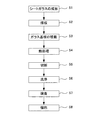
図1は、本実施形態のガラス板の製造方法の流れを示すフローチャートである。製造されるガラス基板は、特に制限されないが、例えば縦寸法及び横寸法のそれぞれが500mm〜3500mmであることが好ましい。ガラス基板の厚さは、0.1〜1.1(mm)の極めて薄い矩形形状の板であることが好ましい。
まず、熔融されたガラスが、例えばフュージョン法あるいはフロート法等の公知の方法により、所定の厚さの帯状ガラスであるシートガラスが成形される(ステップS1)。
次に、成形されたシートガラスが所定の長さの素板であるガラス基板に採板される(ステップS2)。採板により得られたガラス基板は、ガラス基板を保護するシート体と交互に積層してガラス基板の積層体を作製する(ステップS3)。次に、このガラス基板の積層体に対して熱処理を行なう(ステップS4)。このステップS3の処理およびステップS4の処理が本実施形態のアニーリング工程である。アニーリング工程の詳細については後述する。
Hereinafter, the manufacturing method of the glass substrate of this invention is demonstrated in detail.
FIG. 1 is a flowchart showing the flow of the glass plate manufacturing method of the present embodiment. Although the glass substrate manufactured is not specifically limited, For example, it is preferable that each of the vertical dimension and the horizontal dimension is 500 mm to 3500 mm. The glass substrate is preferably an extremely thin rectangular plate having a thickness of 0.1 to 1.1 (mm).
First, the melted glass is formed into a sheet glass, which is a strip glass having a predetermined thickness, by a known method such as a fusion method or a float method (step S1).
Next, the formed sheet glass is sampled on a glass substrate which is a base plate having a predetermined length (step S2). The glass substrate obtained by the plate-making is laminated alternately with a sheet body that protects the glass substrate to produce a laminated body of glass substrates (step S3). Next, heat treatment is performed on the laminated body of glass substrates (step S4). The process of step S3 and the process of step S4 are the annealing process of this embodiment. Details of the annealing step will be described later.
熱処理後のガラス基板は切断工程に搬送され、製品のサイズに切断され、ガラス基板が得られる(ステップS5)。得られたガラス基板には、端面の研削、研磨およびコーナカットを含む端面加工が行われた後、ガラス基板は洗浄される(ステップS6)。洗浄されたガラス基板はキズ、塵、汚れあるいは光学欠陥を含む傷が無いか、光学的検査が行われる(ステップS7)。検査により品質の適合したガラス基板は、ガラス基板を保護する紙と交互に積層された積層体としてパレットに積載されて梱包される(ステップS8)。梱包されたガラス基板は納入先業者に出荷される。 The glass substrate after the heat treatment is conveyed to a cutting process, and is cut into a product size to obtain a glass substrate (step S5). The obtained glass substrate is subjected to end face processing including end face grinding, polishing and corner cutting, and then the glass substrate is washed (step S6). The cleaned glass substrate is optically inspected for scratches, dust, dirt, or scratches including optical defects (step S7). A glass substrate having a quality suitable by inspection is loaded on a pallet and packed as a laminated body alternately laminated with paper protecting the glass substrate (step S8). The packed glass substrate is shipped to a supplier.
このようなガラス基板として、以下のガラス組成のガラス基板が例示される。つまり、以下のガラス組成のガラス基板が製造されるように、熔融ガラスの原料が調合される。
SiO2 55〜80モル%、
Al2O3 8〜20モル%、
B2O3 0〜12モル%、
RO 0〜17モル%(ROはMgO、CaO、SrO及びBaOの合量)。
As such a glass substrate, the glass substrate of the following glass compositions is illustrated. That is, the raw material of molten glass is prepared so that the glass substrate of the following glass compositions is manufactured.
SiO 2 55~80 mol%,
Al 2 O 3 8-20 mol%,
B 2 O 3 0 to 12 mol%,
RO 0 to 17 mol% (RO is the total amount of MgO, CaO, SrO and BaO).
SiO2は60〜75モル%、さらには、63〜72モル%であることが、熱収縮率を小さくするという観点から好ましい。
ROのうち、MgOが0〜10モル%、CaOが0〜10モル%、SrOが0〜10%、BaOが0〜10%であることが好ましい。
SiO 2 is preferably 60 to 75 mol%, and more preferably 63 to 72 mol%, from the viewpoint of reducing the heat shrinkage rate.
Among RO, it is preferable that MgO is 0-10 mol%, CaO is 0-10 mol%, SrO is 0-10%, and BaO is 0-10%.
また、SiO2、Al2O3、B2O3、及びROを少なくとも含み、モル比((2×SiO2)+Al2O3)/((2×B2O3)+RO)は4.5以上であるガラスであってもよい。また、MgO、CaO、SrO、及びBaOの少なくともいずれか含み、モル比(BaO+SrO)/ROは0.1以上であることが好ましい。 Further, at least SiO 2 , Al 2 O 3 , B 2 O 3 , and RO are included, and the molar ratio ((2 × SiO 2 ) + Al 2 O 3 ) / ((2 × B 2 O 3 ) + RO) is 4. The glass which is 5 or more may be sufficient. In addition, it is preferable that at least one of MgO, CaO, SrO, and BaO is included, and the molar ratio (BaO + SrO) / RO is 0.1 or more.
また、モル%表示のB2O3の含有率の2倍とモル%表示のROの含有率の合計は、30モル%以下、好ましくは10〜30モル%であることが好ましい。
また、上記ガラス組成のガラス基板におけるアルカリ金属酸化物の含有率は、0モル%以上0.4モル%以下であってもよい。
また、ガラス中で価数変動する金属の酸化物(酸化スズ、酸化鉄)を合計で0.05〜1.5モル%含み、As2O3、Sb2O3及びPbOを実質的に含まないということは必須ではなく任意である。
The total content of 2-fold and mol% of RO for the content of mol% of B 2 O 3 is 30 mol% or less, it is preferred that preferably 10 to 30 mol%.
Moreover, 0 mol% or more and 0.4 mol% or less may be sufficient as the content rate of the alkali metal oxide in the glass substrate of the said glass composition.
Further, it contains 0.05 to 1.5 mol% of metal oxides (tin oxide and iron oxide) whose valence fluctuates in the glass, and substantially contains As 2 O 3 , Sb 2 O 3 and PbO. It is not essential but optional.
〔アニーリング工程〕
次に、アニーリング工程について詳細に説明する。まず、ステップS2で採板された複数のガラス基板11と複数のシート体12とを交互に1枚ずつ積層してガラス基板の積層体10を作製する(ステップS3)。
[Annealing process]
Next, the annealing process will be described in detail. First, a plurality of
図2は、ガラス基板の積層体10(以下、積層体10という)が載せられたパレット20を示す側面図である。ここで、図2の左側をパレット20の前側、図2の右側をパレット20の後側とする。パレット20には、積層体10が積層方向をほぼ前後方向として載置される。ここで、積層体10の積層方向は前後方向と完全に一致している必要はない。例えば、図2に示すように、ガラス基板11を斜めに立てかける場合、積層方向と前後方向とのなす角はガラス基板11の上下方向とのなす角となる。
パレット20は、基台部21と、載置部22と、背面板23と、等を備える。
基台部21、載置部22および背面板23は、例えば鋼鉄等の金属からなり、溶接等により一体に形成されている。
基台21は略長方形の板状であり、端面にフォークリフトの爪を挿入するための開口21aが設けられている。
載置部22は基台21の上部に固定されており、載置部22の上部にガラス基板の積層体10が載せられる。ここで、載置部22の上面は完全に水平である必要はない。例えば、図2に示すように、ガラス基板11を斜めに立てかける場合、ガラス基板11の立てかけ角度に応じて載置部22の上面を傾斜させておいてもよい。
背面板23は略長方形の板状であり、基台21の上部において、載置部22の後端に載置部22とほぼ垂直に固定されている。背面板23は載置部22の上部に載せられる積層体10の積層方向の後端部を支持する。ここで、背面板23は完全に垂直である必要はない。例えば、図2に示すように、ガラス基板11を斜めに立てかける場合、ガラス基板11の立てかけ角度に応じて背面板23を傾斜させておいてもよい。
FIG. 2 is a side view showing a
The
The
The
The mounting part 22 is fixed to the upper part of the
The back plate 23 has a substantially rectangular plate shape, and is fixed to the rear end of the mounting portion 22 substantially perpendicularly to the mounting portion 22 at the upper portion of the
次に、積層体10について説明する。積層体10は、複数のガラス基板11と、複数のシート体12と、を有する。
Next, the laminate 10 will be described. The
シート体12は、ガラス基板11同士の間に挟まれる。シート体12は積層されるガラス基板11同士の密着を防ぐ役割を果たす。シート体12には、積層体10を熱処理する際の温度に耐えうる耐熱性を有する材料を用いることができる。シート体12は、ガラス基板11よりも高い熱伝導率を有することが好ましい。
このようなシート体12の材料として、例えば、カーボングラファイト、アルミナ繊維、シリカ繊維、ガラス繊維、及び、多孔質セラミックスから選ばれた一種、又は、それらの組合せを選択することができる。
シート体12の厚さは、ガラス基板11の面内方向の熱伝導率を高めるために厚いことが好ましい。一方、積層体10の体積を低減するためにシート体12の厚さは薄いことが好ましい。このため、シート体12の厚さは、0.02mm〜3mm程度であることが好ましい。シート体12の面積は、ガラス基板11同士の密着を防ぐ役割から、ガラス基板11と同程度またはそれ以上であることが好ましい。
The
As a material of such a
The thickness of the
なお、任意の複数のガラス基板11の間に、シート体12に代えて、又はシート体12とともに、積層体10を加熱するための加熱板を介在させてもよい。加熱板として、例えば、電流が流されることで発熱する電極板を用いることができる。この場合、電極板の抵抗値が電極板の温度に応じて変化するため、電極板の温度に応じて電極板を流れる電流量が変化する。このため、電極板を流れる電流量に基づいて加熱板の温度を制御することができる。これにより、複数のガラス基板11間の熱分布を均等に調整することができる。
In addition, you may interpose the heating plate for heating the
本実施形態においては、上記の積層体10を、1対の断熱板15a、15bで挟んだ状態で、積層体10に対し熱処理が行われる。
1対の断熱板15a、15bは、積層体10の積層方向の両端部に配置されている。図2では、断熱板15aが後端部に、断熱板15bが前端部に配置されている。断熱材15a、15bは、ガラス基板よりも熱伝導率が低い材料からなる。ガラス基板よりも熱伝導率が低い材料として、例えば、セラミック、アルミナ、シリカ、及び、ロックウールから選ばれた一種、又は、それらの組合せを選択することができる。
断熱板15a、15bの熱抵抗は、断熱性能を維持するために0.1℃/W以上であることが好ましい。一方、積層体10の端部に配置されるガラス基板11の加熱および冷却を妨げないように、断熱板15a、15bの熱抵抗は10℃/W以下であることが好ましい。断熱板15a、15bの厚さは、断熱性能を維持するために厚いことが好ましい。一方、断熱板15a、15bの厚さは、積層体10の体積を低減するために薄いことが好ましい。このため、断熱板15a、15bの厚さは、10〜50mm程度であることが好ましい。断熱板15a、15bの面積は、積層体の積層方向の外側から端部のガラス基板11への同士の密着を防ぐ役割から、ガラス基板11と同程度またはそれ以上であることが好ましい。
In the present embodiment, heat treatment is performed on the
The pair of
The thermal resistance of the
次に、ステップS4の熱処理について説明する。
ステップS3の処理で作製された積層体10に対して、製造ラインから外れたオフラインで熱処理が行われる。この熱処理では、ガラス基板の積層体を所定の温度の雰囲気下に所定時間放置し、ガラス基板の端部領域から端部領域により囲まれた中央領域にかけての熱分布を一様にすることで、端部領域から中央領域にかけての歪分布が一様になるように調整する。
Next, the heat treatment in step S4 will be described.
A heat treatment is performed off-line off the production line on the laminate 10 produced by the process of step S3. In this heat treatment, the laminated body of the glass substrate is allowed to stand in an atmosphere of a predetermined temperature for a predetermined time, and the heat distribution from the end region of the glass substrate to the central region surrounded by the end region is made uniform, Adjustment is made so that the strain distribution from the end region to the central region is uniform.
具体的には、熱処理を行う炉に上記の積層体10が載せられたパレット20を搬入し、炉内の空気を加熱して所定時間放置することによりガラス基板11を熱処理する。また、ガラス基板11の間に加熱板を介在させる場合には、炉内の空気を加熱するとともに、加熱板により積層体10を内部から加熱する。
熱処理の温度は、ガラス基板11の歪点−400℃の温度から歪点の温度範囲であることが、熱収縮率を低減させ、ガラス基板の歪分布を一様とする点から好ましい。熱処理の時間は、例えば1〜120時間である。熱処理における雰囲気中の温度の時間履歴は特に制限されず、雰囲気の温度が、歪点−400℃の温度から歪点の温度範囲にある時間が少なくとも1時間以上あるとよい。1時間未満であると、熱収縮率が十分に低下せず、120時間より長いと、熱収縮率は十分低減するが、ガラス基板11の生産効率が低下する。
なお、ガラス基板11の歪点は、高精細ディスプレイ用ガラス基板とするために、600℃〜760℃であることが好ましい。例えば、歪点は、661℃である。歪点が低いガラス基板であっても、熱処理することにより、歪点が高いガラス基板と同程度の熱収縮率を実現することができる。この場合、熱処理温度の最低温度は、200℃(=600℃―400℃)以上である。
ガラス基板の積層体が晒される高温の雰囲気は、特に制限されず、酸素含率が5〜50%である雰囲気であってもよく、例えば空気からなる大気雰囲気であってもよい。
Specifically, the
The temperature of the heat treatment is preferably in a temperature range from a strain point of the
The strain point of the
The high temperature atmosphere to which the laminate of the glass substrate is exposed is not particularly limited, and may be an atmosphere having an oxygen content of 5 to 50%, for example, an air atmosphere composed of air.
図3(a)は、ガラス基板11上での点A、Bの位置を示した図であり、図3(b)は、図3(a)のガラス基板11上の点A、Bの各位置における熱履歴を示す図である。ここで、熱履歴とは、熱処理によって変化するガラス基板11の温度の履歴を示すものである。ガラス基板11の積層体10を積層方向に挟んだ状態で、積層体10を熱処理を行う炉に搬入し、炉内の雰囲気の温度を上昇させると、雰囲気の熱が積層体10の積層方向の外側からガラス基板11に伝わる。ガラス基板11の縁を含む縁領域11aは、高温の雰囲気から熱の伝導を受けて、ガラス基板11の縁領域11aに囲まれた中央領域11bに比べて早く昇温する。また、雰囲気を降温し、低温となった雰囲気に高温状態のガラス基板11の縁領域11aは晒されて放熱し、ガラス基板11の中央領域11bに比べて早く降温する。このため、図3(b)に示すように、ガラス基板11上では、点A周辺は、点B周辺より早く昇温、降温する。このように熱履歴に差が生じると、縁領域11aから中央領域11bにかけて(点A周辺から点B周辺にかけて)、熱収縮率が異なり、引っ張りと圧縮応力が生じるために歪が発生する。ガラス基板11面内での熱収縮率を均一して、歪の発生を抑制するためには、ガラス基板11の縁領域11aから中央領域11bかけての温度変化の差をなくす、つまり、熱履歴の差を小さくする必要がある。
FIG. 3A is a diagram showing the positions of points A and B on the
ここで、LTPS、IGZOから構成される半導体層をガラス基板11に形成する温度は、400℃〜600℃(歪点が661℃である場合、歪点より60℃〜260℃低い温度)であるため、この温度範囲におけるガラス基板11の熱収縮率を低減できればよい。このため本実施形態では、ガラス基板11の点A及び点Bの周辺の温度が、400℃〜500℃の温度範囲になるよう熱処理を行う。熱収縮率は、ガラス基板11を熱処理した時の最高温度だけでなく、熱履歴によっても変化する。特に、図3(b)に示すように、熱処理温度の最高温度(例えば、500℃)から、最高温度より50℃〜300℃低い温度(例えば、450℃〜200℃)までの熱履歴が、熱収縮率に大きく影響する。熱収縮率は、熱収縮率を評価する温度、ここでは、LTPS、IGZOから構成される半導体層をガラス基板11に形成する温度である例えば400℃〜500℃で熱処理することにより、この温度領域において熱収縮率が低減する。また、この温度領域400℃〜500℃以下の温度領域においても熱収縮が低減する。つまり、熱収縮率を評価する温度に近い温度では、熱収縮率に大きく影響し、温度が離れるほど、熱収縮率への影響は小さくなる。このため本実施形態では、熱処理温度の最高温度から50℃〜300℃低い温度になるまでの温度領域において、ガラス基板11の面方向での熱履歴の差が抑制されるよう熱処理を行う。図3(b)では、300℃〜500℃の温度範囲における熱履歴の差を示している。ガラス基板11の縁領域11a(点A周辺)と中央領域11b(点B周辺)との熱履歴の差(図3(b)における面積S)を小さくすることにより、ガラス基板11面上の熱収縮率のばらつきが抑制され、歪の発生を抑制することができる。
Here, the temperature at which the semiconductor layer composed of LTPS and IGZO is formed on the
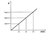
点Aの熱履歴と点Bの熱履歴との差によって形成される面積Sが小さいほど、歪の値は小さくなる。図4は、熱履歴の差を示す面積と歪との関係を示すグラフである。同図に示すように、歪を2 kgf/cm2以下にする場合には、面積がS1以下になるように、ガラス基板11を熱処理する。また、歪を4 kgf/cm2以下にする場合には面積をS2以下に、歪を9 kgf/cm2以下にする場合には面積をS3以下になるように、ガラス基板11を熱処理する。面積S1〜S3の値は、時間×温度、つまり、熱量である。面積S1〜S3の値は、ガラス基板11の大きさ、厚さ、組成等によって任意に変更できる。これにより、高精細ディスプレイのパネル製造時に求められる歪の許容値に応じて、ガラス基板11の熱処理における温度、時間を適宜変更することもできる。
The smaller the area S formed by the difference between the thermal history at point A and the thermal history at point B, the smaller the strain value. FIG. 4 is a graph showing the relationship between the area indicating the difference in thermal history and the strain. As shown in the figure, when the strain is set to 2 kgf / cm 2 or less, the
また、ガラス基板11の中央領域11b(点B周辺)の温度が、縁領域11a(点A周辺)の温度と同様の最高温度に達するように熱処理する。ガラス基板11の中央領域11b(点B周辺)の温度が最高温度に達することにより、縁領域11a(点A周辺)と中央領域11b(点B周辺)との熱収縮率の差が小さくなり、歪の発生を低減することができる。中央領域11b(点B周辺)の温度が最高温度を継続(保持)する時間は、任意であり、例えば、1時間〜4時間であり、より好ましくは、1時間〜2時間である。所定の熱収縮率を達成するために、縁領域11a(点A周辺)から中央領域11b(点B周辺)にかけてのガラス基板11の温度が、最高温度に到達するように熱処理し、歪の発生を抑制するために、ガラス基板11での面方向での熱履歴の差が小さくなるように熱処理する。
Further, heat treatment is performed so that the temperature of the
このような熱処理により、ガラス基板11の熱収縮率を0〜15ppmとすることができる。ガラス基板11の熱収縮率は、0〜12ppmとすることが好ましく、0〜6ppmとすることがより好ましい。このような熱収縮率が、ガラス基板のガラス組成と、熱処理の温度と熱処理時間を調整することにより達成することができる。
By such heat treatment, the thermal shrinkage rate of the
本実施形態では、ガラス基板11よりも熱伝導率が低い1対の断熱板15a、15bでガラス基板11の積層体10を積層方向に挟んだ状態で、積層体10を熱処理を行う炉に搬入し、炉内の雰囲気の温度を上昇させるため、雰囲気の熱が積層体10の積層方向の外側からガラス基板11に伝わることを断熱板15a、15bにより抑制することができる。このため、積層体10を構成する全てのガラス基板11が面内方向外側のみから加熱されることとなり、複数のガラス基板11間の熱分布を一様にすることができる。したがって、熱処理後の各ガラス基板11の熱収縮率のばらつきを低減することができる。
ここで、積層体10の積層方向の任意の位置に加熱板を配置し、複数のガラス基板11間の熱分布が一様となるように加熱板により積層体10を加熱してもよい。
さらに、シート体12としてガラス基板11よりも高い熱伝導率を有する材料を用いることで、ガラス基板11の面内方向の伝熱を促進し、ガラス基板11の端部領域と中央領域との熱分布を一様にすることができる。このため、ガラス基板の歪分布を一様にすることができる。
In the present embodiment, the
Here, a heating plate may be disposed at an arbitrary position in the stacking direction of the stacked
Furthermore, by using a material having a higher thermal conductivity than the
本実施形態で製造されるガラス基板は、フラットパネルディスプレイ用ガラス基板、例えば、液晶ディスプレイ用ガラス基板あるいは、有機ELディスプレイ用のガラス基板として好適である。さらに、本実施形態で製造されるガラス基板は、高精細ディスプレイに用いるLTPS(Low-temperature poly silicon)・TFTディスプレイ用ガラス基板、あるいは、酸化物半導体・TFTディスプレイ用のガラス基板として特に好適である。 The glass substrate manufactured by this embodiment is suitable as a glass substrate for flat panel displays, for example, a glass substrate for liquid crystal displays or a glass substrate for organic EL displays. Furthermore, the glass substrate manufactured in this embodiment is particularly suitable as a glass substrate for LTPS (Low-temperature poly silicon) TFT display used for high-definition displays, or a glass substrate for oxide semiconductor TFT displays. .
本実施形態における熔融ガラスからシートガラスを成形する方法として、フロート法やフュージョン法等が用いられるが、本実施形態のガラス基板のオフラインにおける熱処理を含むガラス基板の製造方法では、フュージョン法(オーバーダウンドロー法)において製造ライン上の徐冷装置を長くすることが困難である点から、フュージョン法に適している。 As a method for forming sheet glass from molten glass in the present embodiment, a float method, a fusion method, or the like is used. In the method for manufacturing a glass substrate including offline heat treatment of the glass substrate in the present embodiment, the fusion method (overdown The draw method is suitable for the fusion method because it is difficult to lengthen the slow cooling device on the production line.
(実験例)
下記ガラス組成を有するガラス基板をフュージョン法の1つであるオーバダウンドロー法により複数作製した。ガラス基板の歪点は660℃であった。
(Experimental example)
A plurality of glass substrates having the following glass composition were produced by an overdown draw method which is one of fusion methods. The strain point of the glass substrate was 660 ° C.
(ガラス組成)
SiO2 67.0モル%、
Al2O3 10.6モル%、
B2O3 11.0モル%、
RO 11.4モル%(ROはMgO、CaO、SrO及びBaOの合量)。
(Glass composition)
SiO 2 67.0 mol%,
Al 2 O 3 10.6 mol%,
B 2 O 3 11.0 mol%,
RO 11.4 mol% (RO is the total amount of MgO, CaO, SrO and BaO).
〔アニーリング〕
このガラス基板に対し、アニーリングを行った。実施例では、ガラス基板を積層し、1対の断熱材の間に挟んで積層体を形成し、熱処理を行なった。比較例では、ガラス基板を積層し、断熱材の間に挟まずに積層体を形成し、熱処理を行った(従来例)。熱処理は、雰囲気温度を500℃とし、放置時間を8時間とした。
〔annealing〕
The glass substrate was annealed. In the examples, a glass substrate was laminated, a laminate was formed between a pair of heat insulating materials, and heat treatment was performed. In the comparative example, a glass substrate was laminated, a laminated body was formed without being sandwiched between heat insulating materials, and heat treatment was performed (conventional example). In the heat treatment, the ambient temperature was 500 ° C., and the standing time was 8 hours.
〔熱収縮率の測定〕
熱処理前に所定のサイズの長方形にガラス基板を切りだし、長辺両端部にケガキ線を入れ、短辺中央部で半分に切断し、2つのガラスサンプルを得る。このうちの一方のガラスサンプルを、熱処理(昇温速度が10℃/分、450℃で1時間放置)する。熱処理をしない他方のガラスサンプルの長さを計測する。さらに、熱処理したガラスサンプルと未処理のガラスサンプルとをつき合わせてケガキ線のずれ量を、レーザ顕微鏡等で測定して、ガラスサンプルの長さの差分を求めることでサンプルの熱収縮量を求めることができる。この熱収縮量である差分と、熱処理前のガラスサンプルの長さを用いて、以下の式により熱収縮率が求められる。このガラスサンプルの熱収縮率をガラス基板の熱収縮率とした。
熱収縮率(ppm)=(差分)/(熱処理前のガラスサンプルの長さ)×106
(Measurement of heat shrinkage rate)
Before heat treatment, a glass substrate is cut into a rectangle of a predetermined size, a marking line is put on both ends of the long side, and cut in half at the center of the short side to obtain two glass samples. One of the glass samples is heat-treated (temperature rising rate is 10 ° C./min, left at 450 ° C. for 1 hour). Measure the length of the other glass sample without heat treatment. Further, the heat-treated glass sample and the untreated glass sample are put together to measure the deviation amount of the marking line with a laser microscope or the like, and the difference in the length of the glass sample is obtained to obtain the thermal contraction amount of the sample. be able to. Using the difference as the amount of heat shrinkage and the length of the glass sample before the heat treatment, the heat shrinkage rate is obtained by the following equation. The thermal shrinkage rate of this glass sample was taken as the thermal shrinkage rate of the glass substrate.
Thermal contraction rate (ppm) = (difference) / (length of glass sample before heat treatment) × 10 6
アニーリング前のガラス基板について熱収縮率を調べたところ、50ppmであった。
アニーリング後のガラス基板について熱収縮率を調べたところ、実施例では、積層方向の端部のガラス基板の熱収縮率は2ppm、積層方向の中央部のガラス基板の熱収縮率は3ppmであった。一方、従来例では、積層方向の端部のガラス基板の熱収縮率は10ppm、積層方向の中央部のガラス基板の熱収縮率は18ppmであった。
このように、1対の断熱板でガラス基板の積層体を積層方向に挟んだ状態で、積層体をガラス基板の面内方向外側から加熱することで、複数のガラス基板間の熱分布を均等にすることができる。このため、熱処理後の各ガラス基板の熱収縮率のばらつきを低減することができる。
When the thermal shrinkage rate of the glass substrate before annealing was examined, it was 50 ppm.
When the thermal shrinkage rate of the glass substrate after annealing was examined, in the example, the thermal shrinkage rate of the glass substrate at the end portion in the stacking direction was 2 ppm, and the thermal shrinkage rate of the glass substrate in the center portion in the stacking direction was 3 ppm. . On the other hand, in the conventional example, the thermal contraction rate of the glass substrate at the end in the stacking direction was 10 ppm, and the thermal contraction rate of the glass substrate at the center in the stacking direction was 18 ppm.
In this way, by heating the laminate from the outside in the in-plane direction of the glass substrate with a pair of heat insulating plates sandwiching the laminate of the glass substrates in the laminating direction, the heat distribution between the plurality of glass substrates is evenly distributed. Can be. For this reason, the dispersion | variation in the thermal contraction rate of each glass substrate after heat processing can be reduced.
以上、本発明のガラス基板の製造方法について詳細に説明したが、本発明は上記実施形態及び実施例等に限定されず、本発明の主旨を逸脱しない範囲において、種々の改良や変更をしてもよいのはもちろんである。 As mentioned above, although the manufacturing method of the glass substrate of this invention was demonstrated in detail, this invention is not limited to the said embodiment, an Example, etc., In the range which does not deviate from the main point of this invention, various improvement and a change are carried out. Of course it is also good.
10 積層体
11 ガラス基板
12 シート体
15a、15b 断熱板
20 パレット
21 基台部
22 載置部
23 背面板
DESCRIPTION OF
Claims (5)
前記アニーリング工程は、
作製された複数のガラス基板をそれぞれシート体の間に挟んだ状態で厚さ方向に積層してガラス基板の積層体を作製する工程と、
作製した前記積層体を熱処理することにより、ガラス基板の熱収縮率を低下させる熱処理工程と、を含み、
前記熱処理工程において、前記ガラス基板よりも熱伝導率が低い1対の断熱板で前記積層体を積層方向に挟んだ状態で、前記複数のガラス基板の熱分布を揃えるように、前記積層体を前記ガラス基板の面内方向外側から加熱することを特徴とするガラス基板の製造方法。 A method for producing a glass substrate including an annealing step of the produced glass substrate,
The annealing step includes
A step of laminating a plurality of produced glass substrates in a thickness direction in a state of being sandwiched between sheet bodies, and producing a laminated body of glass substrates;
A heat treatment step of reducing the thermal shrinkage rate of the glass substrate by heat-treating the produced laminate, and
In the heat treatment step, the laminated body is arranged so that the heat distribution of the plurality of glass substrates is made uniform in a state where the laminated body is sandwiched in a laminating direction by a pair of heat insulating plates having a thermal conductivity lower than that of the glass substrate. A method for producing a glass substrate, comprising heating from the outside in the in-plane direction of the glass substrate.
The glass according to any one of claims 1 to 4, wherein the sheet body is composed of one kind selected from carbon graphite, alumina fiber, silica fiber, glass fiber, and porous ceramics, or a combination thereof. A method for manufacturing a substrate.
Priority Applications (1)
| Application Number | Priority Date | Filing Date | Title |
|---|---|---|---|
| JP2014134539A JP2016011233A (en) | 2014-06-30 | 2014-06-30 | Manufacturing method of glass substrate |
Applications Claiming Priority (1)
| Application Number | Priority Date | Filing Date | Title |
|---|---|---|---|
| JP2014134539A JP2016011233A (en) | 2014-06-30 | 2014-06-30 | Manufacturing method of glass substrate |
Publications (1)
| Publication Number | Publication Date |
|---|---|
| JP2016011233A true JP2016011233A (en) | 2016-01-21 |
Family
ID=55228188
Family Applications (1)
| Application Number | Title | Priority Date | Filing Date |
|---|---|---|---|
| JP2014134539A Pending JP2016011233A (en) | 2014-06-30 | 2014-06-30 | Manufacturing method of glass substrate |
Country Status (1)
| Country | Link |
|---|---|
| JP (1) | JP2016011233A (en) |
-
2014
- 2014-06-30 JP JP2014134539A patent/JP2016011233A/en active Pending
Similar Documents
| Publication | Publication Date | Title |
|---|---|---|
| JP5428288B2 (en) | Glass plate manufacturing method and manufacturing equipment | |
| US20170088454A1 (en) | Method for reducing warpage occurring in glass sheet due to chemical strengthening treatment, method for producing glass sheet for chemical strengthening, and method for producing chemically strengthened glass sheet | |
| JP5428287B2 (en) | Glass plate manufacturing method and manufacturing equipment | |
| TWI716561B (en) | Alkali-free glass substrate and method for manufacturing alkali-free glass substrate | |
| JP6380101B2 (en) | Glass substrate and slow cooling method thereof | |
| WO2009081740A1 (en) | Process and apparatus for producing glass plate | |
| JP2011219361A (en) | Glass sheet and method of forming the same | |
| JP6082434B2 (en) | Glass substrate manufacturing method and glass substrate | |
| JP6379678B2 (en) | Manufacturing method of glass substrate | |
| JP5729653B2 (en) | Sheet glass | |
| JP6454188B2 (en) | Manufacturing method of glass substrate | |
| JP2016011233A (en) | Manufacturing method of glass substrate | |
| JP2016011235A (en) | Manufacturing method of glass substrate | |
| JP2016011234A (en) | Manufacturing method of glass substrate | |
| JP6552839B2 (en) | Manufacturing method of glass substrate | |
| JP2016011232A (en) | Manufacturing method of glass substrate | |
| JP6403458B2 (en) | Manufacturing method of glass substrate | |
| JP2016011237A (en) | Manufacturing method of glass substrate | |
| TWI580650B (en) | Glass substrate manufacturing method and glass substrate | |
| JP2014231438A (en) | Strengthened glass and production method thereof | |
| WO2016068069A1 (en) | Glass base plate heat processing method and glass base plate production method | |
| EP4317092A1 (en) | Glass plate for chemical reinforcement, method for manufacturing reinforced glass plate, and glass plate | |
| TWI679174B (en) | Heat treatment method of glass substrate and manufacturing method of glass substrate | |
| WO2022107559A1 (en) | Electronic device manufacturing method and glass plate group | |
| JP2016011240A (en) | Manufacturing method of glass substrate |