JP2016000002A - Plant factory apparatus and pallet movement control method - Google Patents
Plant factory apparatus and pallet movement control method Download PDFInfo
- Publication number
- JP2016000002A JP2016000002A JP2012226299A JP2012226299A JP2016000002A JP 2016000002 A JP2016000002 A JP 2016000002A JP 2012226299 A JP2012226299 A JP 2012226299A JP 2012226299 A JP2012226299 A JP 2012226299A JP 2016000002 A JP2016000002 A JP 2016000002A
- Authority
- JP
- Japan
- Prior art keywords
- pallet
- shelf
- plant factory
- shelves
- plant
- Prior art date
- Legal status (The legal status is an assumption and is not a legal conclusion. Google has not performed a legal analysis and makes no representation as to the accuracy of the status listed.)
- Pending
Links
Images


Classifications
-
- A—HUMAN NECESSITIES
- A01—AGRICULTURE; FORESTRY; ANIMAL HUSBANDRY; HUNTING; TRAPPING; FISHING
- A01G—HORTICULTURE; CULTIVATION OF VEGETABLES, FLOWERS, RICE, FRUIT, VINES, HOPS OR SEAWEED; FORESTRY; WATERING
- A01G9/00—Cultivation in receptacles, forcing-frames or greenhouses; Edging for beds, lawn or the like
- A01G9/14—Greenhouses
- A01G9/1423—Greenhouse bench structures
-
- Y—GENERAL TAGGING OF NEW TECHNOLOGICAL DEVELOPMENTS; GENERAL TAGGING OF CROSS-SECTIONAL TECHNOLOGIES SPANNING OVER SEVERAL SECTIONS OF THE IPC; TECHNICAL SUBJECTS COVERED BY FORMER USPC CROSS-REFERENCE ART COLLECTIONS [XRACs] AND DIGESTS
- Y02—TECHNOLOGIES OR APPLICATIONS FOR MITIGATION OR ADAPTATION AGAINST CLIMATE CHANGE
- Y02A—TECHNOLOGIES FOR ADAPTATION TO CLIMATE CHANGE
- Y02A40/00—Adaptation technologies in agriculture, forestry, livestock or agroalimentary production
- Y02A40/10—Adaptation technologies in agriculture, forestry, livestock or agroalimentary production in agriculture
- Y02A40/25—Greenhouse technology, e.g. cooling systems therefor
Abstract
Description
本発明は、植物工場装置及びパレット移動制御方法に関する。 The present invention relates to a plant factory apparatus and a pallet movement control method.
近年、施設内で、植物の生育に必要な環境を照明、空調、風量、養液供給等により人工的に制御し、季節を問わず連続的に安全な農産物を生産できるシステム(植物工場)が開発されている。植物工場は、安全な食料の供給、食材の周年供給などを目的とした、環境保全型の生産システムである。 In recent years, a system (plant factory) that can artificially control the environment required for plant growth in facilities by lighting, air conditioning, air volume, nutrient solution supply, etc., and continuously produce safe agricultural products regardless of the season Has been developed. The plant factory is an environment-conserving production system for the purpose of supplying safe food and the annual supply of ingredients.
また、このような植物工場では、内部の栽培環境の管理として、照明、温度、湿度、CO2濃度、風量等を適切に制御しているので、生産される農産物は高品質で安心・安全であり、かつ、短期間で出荷することができることも特徴である。 Also, in such plant factories, lighting, temperature, humidity, CO2 concentration, air volume, etc. are appropriately controlled to manage the internal cultivation environment, so the agricultural products produced are of high quality, safe and secure. In addition, it can be shipped in a short period of time.
従来技術として、植物を栽培しているベッドに供給する養液量を適切に制御する技術がある(特許文献1参照)。 As a conventional technique, there is a technique for appropriately controlling the amount of nutrient solution supplied to a bed where plants are cultivated (see Patent Document 1).
植物工場では、内部で栽培される植物をできるだけ均一に生育するために、内部の栽培環境を均一な状態にする必要がある。しかし、LEDライトの位置、空気攪拌機の吹き出し口の位置や風向、養液の供給方法等により、植物工場において必ずしも均一な環境を作り出すことができないという課題があった。 In a plant factory, in order to grow plants grown inside as uniformly as possible, it is necessary to make the inside cultivation environment uniform. However, there has been a problem that a uniform environment cannot always be created in a plant factory depending on the position of the LED light, the position and wind direction of the air stirrer outlet, the feeding method of the nutrient solution, and the like.
本発明は、例えば、上記のような課題を解決するためになされたものであり、植物工場内部において均一な環境を提供することにより、植物栽培の育成不良や育成のバラツキ等を解消し、バラツキのない高品質な農産物を育成することができる植物工場装置を提供する。 The present invention has been made, for example, in order to solve the above-described problems, and by providing a uniform environment inside the plant factory, it is possible to eliminate plant cultivation failure, variation in growth, and the like. A plant factory device that can grow high-quality agricultural products without any problems.
本発明に係る植物工場装置は、
上下方向に所定の間隔で配置された複数の長手形状の棚と、植物が植えられるパレットであって前記複数の棚の少なくともいずれかに少なくともひとつ配置されるパレットとを内部に収納する外郭ケースを備え、前記外郭ケースの内部の管理された栽培環境のもとで前記パレットに植えられた植物を栽培する植物工場装置において、
制御を受けることによって、前記パレットを、前記パレットが配置された棚の長手方向に移動させるとともに、前記パレットを上下に位置する2つの棚の一方の棚から他方の棚に移動させるパレット移動機構と、
前記パレット移動機構に対する前記制御によって、前記パレットを停止状態から移動させ、移動状態から停止させることを繰り返す制御部と
を備えることを特徴とする。
The plant factory apparatus according to the present invention,
An outer case that houses therein a plurality of longitudinal shelves arranged at predetermined intervals in the vertical direction and a pallet on which plants are planted and at least one pallet arranged on at least one of the plurality of shelves. In a plant factory apparatus for cultivating a plant planted on the pallet under a controlled cultivation environment inside the outer case,
A pallet moving mechanism that moves the pallet in the longitudinal direction of the shelf on which the pallet is arranged and moves the pallet from one shelf to the other shelf on the top and bottom by receiving control. ,
And a controller that repeatedly moves the pallet from the stopped state and stops the pallet from the moving state by the control of the pallet moving mechanism.
前記制御部は、
前記パレット移動機構に対する前記制御によって、前記パレットを間歇的に移動させることで、前記複数の棚のいずれかの棚の所定の位置から移動を始め、前記複数の棚の全ての棚を移動して前記所定の位置に戻る循環動作を前記パレットにさせることを特徴とする。
The controller is
By moving the pallet intermittently by the control on the pallet moving mechanism, the movement starts from a predetermined position of any of the plurality of shelves, and all the shelves of the plurality of shelves are moved. The pallet is caused to circulate back to the predetermined position.
前記植物工場装置は、
前記複数の棚の少なくともいずれかに備えられた養液パンであって、当該棚に配置されている前記パレットに植えられた植物に養液を供給する養液パンを備えることを特徴とする。
The plant factory device is:
A nutrient solution pan provided on at least one of the plurality of shelves, wherein the nutrient solution pan supplies the nutrient solution to the plants planted on the pallet arranged on the shelf.
前記植物工場装置は、
前記養液パンが備えられた棚である養液棚に設置され、前記パレット移動機構により前記パレットが前記養液棚から前記養液棚の上方の棚に移動する場合に、前記パレットを傾斜させて前記養液パンから供給される養液の液切りをするパレット傾斜機構を備えることを特徴とする。
The plant factory device is:
When the pallet is moved from the nutrient solution shelf to the shelf above the nutrient solution shelf by the pallet moving mechanism, the pallet is tilted. And a pallet tilting mechanism for draining the nutrient solution supplied from the nutrient solution pan.
前記植物工場装置は、
前記複数の棚のうち最下段の棚の下方に設置された空気攪拌機であって、前記最下段の棚の下方に形成された吹き出し口から上方に向けて空気を吹き出すことにより、外郭ケースの内部の空気を攪拌する空気攪拌機を備え、
前記空気攪拌機は、
前記最下段の棚により形成される面の法線方向から所定の角度の範囲内に向けて、前記吹き出し口から空気を吹き出すことを特徴とする。
The plant factory device is:
An air stirrer installed below a lowermost shelf among the plurality of shelves, wherein air is blown upward from a blowout port formed below the lowermost shelf, so that the inside of the outer case Equipped with an air stirrer to stir the air of
The air stirrer
Air is blown out from the outlet in a range of a predetermined angle from a normal direction of a surface formed by the lowermost shelf.
前記空気攪拌機は、
前記最下段の棚により形成される面の法線方向から45度の範囲内に向けて、前記吹き出し口から空気を吹き出すことを特徴とする。
The air stirrer
Air is blown out from the outlet in a range of 45 degrees from the normal direction of the surface formed by the lowermost shelf.
前記外郭ケースは、
前記複数の棚のいずれかの棚の端部近傍に開閉扉を備えることを特徴とする。
The outer case is
An opening / closing door is provided in the vicinity of an end of one of the plurality of shelves.
前記制御部は、
前記パレットの移動と停止とを定期と不定期とのいずれかで繰り返させることを特徴とする。
The controller is
The movement and stop of the pallet are repeated either regularly or irregularly.
前記パレットは、前記複数の棚の各棚に所定数配置されており、
前記複数の棚の各棚は、
前記制御部が前記パレットを停止した場合に、前記パレットがすき間なく配置され、
前記外郭ケースの内部は、前記パレットがすき間なく配置された各棚により複数の空間領域に仕切られることを特徴とする。
A predetermined number of the pallets are arranged on each of the plurality of shelves,
Each shelf of the plurality of shelves
When the control unit stops the pallet, the pallet is arranged without gaps,
The inside of the outer case is divided into a plurality of space areas by shelves in which the pallets are arranged without gaps.
前記パレットがすき間なく配置された各棚により仕切られた各空間領域は、密閉されていることを特徴とする。 Each space area partitioned by each shelf in which the pallets are arranged without gaps is hermetically sealed.
本発明に係るパレット移動制御方法は、
上下方向に所定の間隔で配置された複数の長手形状の棚と、植物が植えられるパレットであって前記複数の棚の少なくともいずれかに少なくともひとつ配置されるパレットとを内部に収納する外郭ケースを備え、前記外郭ケースの内部の管理された環境のもとで前記パレットに植えられた植物を栽培する植物工場装置のパレット移動制御方法において、
前記パレットを停止状態から移動させ、移動状態から停止させることを繰り返すパレット移動制御工程を備えることを特徴とする。
The pallet movement control method according to the present invention includes:
An outer case that houses therein a plurality of longitudinal shelves arranged at predetermined intervals in the vertical direction and a pallet on which plants are planted and at least one pallet arranged on at least one of the plurality of shelves. In a pallet movement control method of a plant factory apparatus for cultivating a plant planted on the pallet under a controlled environment inside the outer case,
A pallet movement control step is included, in which the pallet is moved from a stopped state and repeatedly stopped from the moved state.
前記パレット移動制御工程は、
前記パレットを、前記パレットが配置された棚の長手方向へ移動させるとともに、上下に位置する2つの棚の一方の棚から他方の棚へ移動させることを特徴とする。
The pallet movement control step includes
The pallet is moved in the longitudinal direction of the shelf on which the pallet is arranged, and is moved from one shelf to the other shelf of two shelves positioned above and below.
前記パレット移動制御工程は、
前記パレットを間歇的に移動させることで、複数の棚のいずれかの棚の所定の位置から移動を始め、前記複数の棚の全ての棚を移動して前記所定の位置に戻る循環動作を前記パレットにさせることを特徴とする。
The pallet movement control step includes
By moving the pallet intermittently, the circulation operation starts from a predetermined position of any one of the plurality of shelves, moves all the shelves of the plurality of shelves, and returns to the predetermined position. It is characterized by having a pallet.
本発明に係る植物工場装置によれば、上下方向に所定の間隔で配置された複数の長手形状の棚と、植物が植えられるパレットであって前記複数の棚の少なくともいずれかに少なくともひとつ配置されるパレットとを内部に収納する外郭ケースを備え、前記外郭ケースの内部の管理された栽培環境のもとで前記パレットに植えられた植物を栽培する植物工場装置において、制御を受けることによって、前記パレットを、前記パレットが配置された棚の長手方向に移動させるとともに、前記パレットを上下に位置する2つの棚の一方の棚から他方の棚に移動させるパレット移動機構と、前記パレット移動機構に対する前記制御によって、前記パレットを停止状態から移動させ、移動状態から停止させることを繰り返す制御部とを備えるので、植物工場装置内部において栽培されている植物の栽培環境を均一化することができる。したがって、植物栽培の育成不良や育成のバラツキ等を解消し、バラツキのない高品質な農産物を育成することができるという効果を奏する。 According to the plant factory apparatus of the present invention, there are a plurality of longitudinal shelves arranged at predetermined intervals in the vertical direction, and a pallet on which plants are planted, and at least one is arranged on at least one of the plurality of shelves. A plant case for cultivating a plant planted on the pallet under a controlled cultivation environment inside the outer case, and receiving the control, A pallet moving mechanism for moving the pallet in the longitudinal direction of the shelf on which the pallet is arranged and moving the pallet from one shelf to the other shelf of the two shelves positioned above and below, and the pallet moving mechanism with respect to the pallet moving mechanism And a control unit that repeatedly moves the pallet from the stopped state and stops from the moved state by the control. It is possible to equalize the cultivation environment of the plant to be cultivated in the internal field device. Therefore, there is an effect that it is possible to cultivate a high-quality agricultural product free from variation, which eliminates plant cultivation failure and variation in growth.
以下、本発明の実施の形態について、図を用いて説明する。なお、各実施の形態の説明において、「上」、「下」、「左」、「右」、「前」、「後」、「表」、「裏」といった方向は、説明の便宜上、そのように記しているだけであって、装置、器具、部品等の配置や向き等を限定するものではない。 Hereinafter, embodiments of the present invention will be described with reference to the drawings. In the description of each embodiment, the directions such as “up”, “down”, “left”, “right”, “front”, “back”, “front”, “back” are However, it is not intended to limit the arrangement or orientation of devices, instruments, parts, or the like.
実施の形態1.
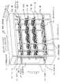
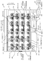
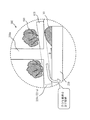
図1は、本実施の形態に係る植物工場装置100の斜視図である。図2は、本実施の形態に係る植物工場装置100の構成及びパレット150の移動を示す正面図であり、下部機器収納部120については内部の構成を模式的に表している図である。図3は、図2に示す植物工場装置100において、空気攪拌機360の空気の吹き出し方向を示した図である。
図1〜図3を用いて、植物工場装置100の全体構造について説明する。
Embodiment 1 FIG.
FIG. 1 is a perspective view of a
The whole structure of the
図1に示すように、植物工場装置100は、外郭ケース110(外殻ケース)を備える。
外郭ケース110は、スチール製の枠組み部111と、枠組み部111の開口を塞ぐ透明あるいは半透明の樹脂製の板等によるカバー部112から構成されている。枠組み部111は、スチール製の他に、他の金属製、樹脂製、木製などでもよい。また、カバー部112は、透明、半透明、あるいは不透明でもよく、樹脂製フィルム、金属板、木製板、ガラス板などでもよい。
As shown in FIG. 1, the
The
外郭ケース110は、内部が密閉されるように形成されている。外郭ケース110は、直方体である。外郭ケース110のサイズは、例えば、高さ2000mm、幅2400mm、奥行き1000mm程度である。このサイズは一例であり、このサイズよりも大きくても小さくても、本実施の形態は適用可能である。
The
植物工場装置100は、外郭ケース110の内部に、複数の棚220、パレット150が収納される。また、複数の棚220の最下段の棚220aの下部は、下部機器収納部120となっている。
In the
複数の棚220は、上下方向に所定の間隔で配置されている。図1及び図2に示すように、植物工場装置100は、4段の棚220a,220b,220c,220dを備える。
棚220は、例えば、長方形をなし、外郭ケース110の幅方向(長手方向)に沿って長手形状に形成される。棚220は、少なくとも2段あればよいが、3段、4段、5段以上でもよい。
The plurality of shelves 220 are arranged at predetermined intervals in the vertical direction. As shown in FIGS. 1 and 2, the
The shelf 220 has a rectangular shape, for example, and is formed in a longitudinal shape along the width direction (longitudinal direction) of the
パレット150は、植物の苗をセットする苗パレット、栽培プレート、栽培ベッド、苗ベッドなどども呼ばれるものである。
複数の棚220の各棚には、少なくともひとつのパレット150が配置されている。本実施の形態では、図2に示すように、1つの棚220に、5つのパレット150が配置されている。5つのパレット150は任意の間隔で棚220に並べられていてもよいが、好ましくは一定の間隔で棚220に並べられるのがよい。
The
At least one
本実施の形態に係る植物工場装置100は、パレット150を棚220の長手方向へ移動させる水平移動機構221と、パレット150を棚から棚へ上下方向に移動させる上下移動機構230とを備えている。
The
また、植物工場装置100は、これらの水平移動機構221、上下移動機構230を制御することにより、パレット150を間歇的に移動させる可動制御部300を備える。可動制御部300は、パレット150を間歇的に移動させることにより、パレット150を植物工場装置100の内部において循環させ、内部で栽培されている植物400の栽培環境の均一化を図る。
The
可動制御部300は、例えば、ネットワーク600を介して端末装置500と接続される。植物工場装置100の管理者(ユーザともいう)は、端末装置500から植物工場装置100の可動制御部300に制御信号(制御命令510)を送信する。あるいは、植物工場装置100の管理者は、植物工場装置100が備える入力部(図示していない)から可動制御部300に制御命令510を入力してもよい。
制御命令510とは、植物工場装置100の内部の栽培環境を制御するための信号である。制御命令510には、光合成を促進するLEDライト、温度・湿度を制御するエアコン、CO2濃度を制御するCO2濃度コントローラー、風量を制御する空気攪拌機を制御する信号が含まれる。また、制御命令510には、パレット150の移動に関する制御信号が含まれる。
The
The
パレット150は、植物400の苗ポットを設置するための苗ポット用開口151が形成されている。本実施の形態では、1つのパレット150に6つの苗ポット用開口151が形成されている。
パレット150の長手方向(以下、パレット長手方向)の長さは、棚220の短手方向の長さよりもやや短い。また、パレット150の短手方向(以下、パレット短手方向)の長さは、例えば、棚220の長手方向の長さの約7分の1程度である。これにより、パレット150の短手方向の長さの2分の1程度の間隔を有して、5つのパレット150を棚220に配置することができる。
The
The length of the
ただし、上記以外の間隔で並べても構わないし、1つの棚220に並べるパレット150の数も、パレット150のサイズも、上記以外の数やサイズであっても本実施の形態は適用可能である。
また、パレット150は、全て同一形状であることが好ましいが、大きさや苗ポット用開口の数が異なるパレットが混在していても、本実施の形態は適用することができる。
However, they may be arranged at intervals other than those described above, and this embodiment can be applied even if the number of
Moreover, although it is preferable that all the
ここで、パレット150を棚220に配置する方法の一例について説明する。
例えば、棚220は、長方形の枠部から構成されているものとする。すなわち、棚220は、枠のみであり、ほぼ全面が開口しているものとする。
図1に示すように、パレット150は、パレット長手方向の両端部の両縁部が、棚220の短手方向端部の両枠部に取り付けられる。図2に示すように、パレット150の裏面(下方の面)は枠の開口から露出しており、パレット150に設置されている植物400が植わっているポットも植物400の根側がパレット150の下方の面から露出している。
Here, an example of a method for arranging the
For example, the shelf 220 is assumed to be composed of a rectangular frame. That is, it is assumed that the shelf 220 is only a frame, and almost the entire surface is open.
As shown in FIG. 1, the
図2に示すように、最下段の棚220aの下部には、養液パン330が設置されている。養液パン330には、植物の栽培に必要な栄養分を配合した養液が投入されている。養液パン330の中の養液に、最下段の棚220aに配置されているパレット150に植えられている植物400の根側が浸されることにより、植物400に養液が供給される。
言い換えると、パレット150の植物400は、最下段の棚220aを通過する際に、養液パン330の養液を吸収する。
As shown in FIG. 2, a
In other words, the
上記の説明では、棚220は枠のみで形成されているものとしたが、パレット150に植えられている植物400の根側が棚200の開口から露出して養液パン330の養液に浸される構造であれば、枠だけの構造でなくてもよい。
例えば、棚220は、枠のところどころに短手方向に渡って細い板等が渡されていてもよい。枠のところどころの短手方向に細い板等が渡されていることにより、棚220の重量に対する耐久性が増す。
In the above description, the shelf 220 is assumed to be formed of only a frame, but the root side of the
For example, the shelf 220 may be provided with a thin plate or the like across the short direction in some places of the frame. The durability against the weight of the shelf 220 is increased by passing a thin plate or the like in the short direction of the frame.
図2に示すように、水平移動機構221は、各棚220a,220b,220c,220dに配設されている。図2に示すように、水平移動機構221は、各棚220a,220b,220c,220dの点線で囲んだ位置(水平移動機構221a,221b,221c,221d)に配設されている。水平移動機構221は、各棚220a,220b,220c,220dに配置されているパレット150を長手方向(以下、左右方向ともいう)に移動させる機構である。
As shown in FIG. 2, the horizontal movement mechanism 221 is disposed on each
水平移動機構221は、例えば、棚220を形成する枠のうち、向かい合う長手方向に伸びた枠225(図1の枠225d参照)の内面に、レールやベルトなどの左右方向ガイド部を配設することにより実現することができる。水平移動機構221は、この左右方向ガイド部がパレット150のパレット長手方向両側の端部と係合し、パレット150のパレット長手方向両側の端部を左右方向にガイドすることで、パレット150を左右方向へ移動させる。
The horizontal movement mechanism 221 includes, for example, left and right guide portions such as rails and belts on the inner surface of a frame 225 (see frame 225d in FIG. 1) that extends in the opposite longitudinal direction among the frames that form the shelf 220. Can be realized. The horizontal movement mechanism 221 engages the ends of the
また、図2に示すように、棚220aと棚220bとの間に上下移動機構230aが配設される。上下移動機構230aは、棚220aから棚220bにパレット150を移動させる機構である。
棚220bと棚220cとの間に上下移動機構230bが配設される。上下移動機構230bは、棚220bから棚220cにパレット150を移動させる機構である。
棚220cと最上段の棚220dとの間に上下移動機構230cが配設される。上下移動機構230cは、棚220cから棚220dにパレット150を移動させる機構である。
Further, as shown in FIG. 2, a
A
A
さらに、図2に示すように、棚220dと棚220aとの間を結ぶ上下移動機構230dが配設される。上下移動機構230dは、棚220dから棚220aにパレット150を移動させる機構であり、下方移動機構240とする。
Further, as shown in FIG. 2, a
上下移動機構230は、例えば、上下方向に配設されたレールやベルトなどから構成される上下方向ガイド部により実現することができる。
上下移動機構230は、水平移動機構221の左右方向ガイド部により、上下方向ガイド部の位置まで移動してきたパレット150を上下方向に移動させる。
The vertical movement mechanism 230 can be realized by, for example, a vertical guide portion configured by a rail, a belt, or the like arranged in the vertical direction.
The vertical movement mechanism 230 moves the
例えば、パレット150は、水平移動機構221の左右方向ガイド部による移動により上下方向ガイド部の位置まで移動されると、左右方向ガイド部との係合が外れ、上下方向ガイド部と係合する構造とする。そして、パレット150は、上下方向ガイド部と係合した状態で、上下方向ガイド部により上下方向に移動することができる。
For example, when the
パレット150は、上下移動機構230の上下方向ガイド部による移動により別の棚220まで移動されると、上下方向ガイド部との係合が外れ、左右方向ガイド部と係合する構造とする。そして、パレット150は、左右方向ガイド部と係合した状態で、左右方向ガイド部により左右方向に移動することができる。
When the
次に、植物工場装置100の内部の環境を適切に保つための環境調整機器について説明する。図2に示す下部機器収納部120は、内部の構成をわかりやすくするために模式的に図示したものである。
Next, an environment adjusting device for appropriately maintaining the environment inside the
図2に示すように、下部機器収納部120には、植物工場装置100の内部の環境を適切に保つための環境調整機器が収納される。図1に示すように、外郭ケース110の上部の上部機器収納部121に環境調整機器が収納されていても構わない。
As shown in FIG. 2, the lower
外郭ケース110の上面の内側には、天面LEDライト371が設置されている。上部機器収納部121には、例えば、天面LEDライト371の光量を調節するための点灯装置、電源装置等が収納されていてもよい。
また、パレット150の裏面には、防水構造を施した各段LEDライト372が配設されている。各段LEDライト372は、パレット150が停止した状態では、下段のパレット150の植物400に対して、光合成に必要な光を放射することができる。
A
Further, each
図2においては、パレット150の裏面の各段LEDライト372についての説明をわかりやすくするために、パレット150の裏面(底面)が棚220の下面から下方に露出している状態に記載している。しかし、パレット150の裏面と棚220の下面とは略同一平面状にあるような位置関係でもよい。あるいは、パレット150の裏面の方が、棚220の下面よりも上方に位置するような位置関係でもよい。
In FIG. 2, the back surface (bottom surface) of the
植物工場装置100は、環境調整機器として、エアコン310(エア・コンディショナー)、液肥タンク320、養液パイプ322、開閉バルブ323(自動養液投入機)、空気攪拌機360を下部機器収納部120に収納する。
The
また、上述したように、植物工場装置100は、パレット150を棚220の長手方向へ移動させる水平移動機構221、棚から棚へ上下方向に移動させる上下移動機構230を備えている。
これらの水平移動機構221、上下移動機構230を制御する可動制御部300も、下部機器収納部120に収納されている。
Further, as described above, the
The
図1に示すように、下部機器収納部120のカバー部112は、不透明な板材となっており、内部の機器を隠して植物工場装置100の意匠性が向上するようにしている。
As shown in FIG. 1, the cover part 112 of the lower
エアコン310(エア・コンディショナー)は、植物工場装置100内部の温度・湿度を制御する。
液肥タンク320は、養液を貯留するタンクである。養液パン330には、養液パイプ322を介して液肥タンク320から養液が投入される。
養液パイプ322には、開閉バルブ323(自動養液投入機)が設置されている。例えば、外部からの制御命令510により開閉バルブ323(自動養液投入機)が制御され、養液パン330に投入される養液の量が自動的に調節される。また、手動により養液パン330に投入される養液の量を調節することもできる構成としてもよい。
The air conditioner 310 (air conditioner) controls the temperature and humidity inside the
The
The
空気攪拌機360は、植物工場装置100(外郭ケース110)の内部の空気を攪拌する。空気攪拌機360は、空気吹き出し口361を備える。空気攪拌機360は、例えば、最下段の棚200aの下方の2箇所に設置される。あるいは、空気攪拌機360は、3箇所、4箇所に設置されていてもよい。
The
図3に示すように、空気攪拌機360は、空気吹き出し口361から上方に向けて空気を吹き出すことにより、外郭ケース110内部の空気を攪拌する。このように、空気の攪拌を下方から上方への垂直方向に実施することにより、植物工場装置100内部の温度・湿度・CO2・風量を均一化することができる。
As shown in FIG. 3, the
空気攪拌機360は、最下段の棚200aにより形成される面の法線方向Pから所定の角度(α度)の範囲内に向けて、空気吹き出し口361から空気を吹き出す。
空気攪拌機360は、例えば、法線方向Pから45度(α=45度)の範囲内に向けて、空気吹き出し口361から空気を吹き出す。
空気攪拌機360が空気を吹き出す角度としては、45度以内が好ましいが、50度、60度以内でも効果がある。あるいは、空気攪拌機360を3台以上にして、空気を吹き出す角度を30度以内としてもよい。
The
The
The angle at which the
図3に示すように、空気攪拌機360が所定の角度(α度)の範囲内に向けて空気吹き出し口361から空気を吹き出すことにより、効果的に植物工場装置100内に空気が行き渡り、植物工場装置100内の環境の均一化に効果がある。
As shown in FIG. 3, when the
次に、図2を用いて、植物工場装置100の可動制御部300によるパレット移動制御方法について説明する。
Next, the pallet movement control method by the
上述したように、水平移動機構221及び上下移動機構230は、制御を受けることによって、パレット150を、パレット150が配置された棚220の長手方向に移動させるとともに、パレット150を上下に位置する2つの棚の一方の棚から他方の棚に移動させるパレット移動機構の一例である。
As described above, the horizontal movement mechanism 221 and the vertical movement mechanism 230 are controlled to move the
また、可動制御部300は、水平移動機構221及び上下移動機構230に対する制御によって、パレット150を停止状態から移動させ、移動状態から停止させることを繰り返す。これは、電源をオンオフすることではなく、電源はオンの状態のままで停止状態から移動させ、移動状態から停止させる制御をする。すなわち、可動制御部300は、間歇的にパレット150を移動させる。
Further, the
可動制御部300は、水平移動機構221及び上下移動機構230に対する制御によって、パレット150を間歇的に移動させることで、複数の棚220のいずれかの棚の所定の位置から移動を始め、複数の棚の全ての棚を移動して所定の位置に戻る循環動作をパレット150にさせる。
可動制御部300は、このようなパレット150の移動と停止とを、定期あるいは不定期に繰り返す制御を実行する。
The
The
次に、可動制御部300によりパレット150を間歇的に循環させる具体例について説明する。
可動制御部300に対しては、ユーザは、例えば、ネットワーク600を介して端末装置500から制御命令510を送信することができる。あるいは、植物工場装置100に可動制御部300に制御命令510を入力する入力部を備えていてもよい。あるいは、予め植物工場装置100の可動制御部300に可動制御プログラムをインストールしておき、全て自動で制御するものとしてもよい。
Next, a specific example in which the
For the
制御命令510としては、例えば、間歇モードか連続移動モードかの選択、間歇モードの場合のパレット150の移動の時間間隔、パレット150の移動時の速さなどが設定できるものとする。
間歇モードは、パレット150の移動が移動と停止とを定期あるいは不定期に繰り返す方式である。
連続移動モードは、パレット150の移動が連続して移動する方式である。植物工場装置100に対して、間歇的な移動でなく、連続移動をするように連続移動モードの制御命令510を入力することができる。パレット150の連続移動あるいは移動の停止を指示することができることにより、栽培を開始するにあたり、植物工場装置100内部に全てのパレット150(図2では20個のパレット)を設定する際に便利となる。
As the
The intermittent mode is a method in which the movement of the
The continuous movement mode is a method in which the movement of the
速さは、実際の速さを指定できてもよいし、「速い、普通、遅い」などの所定の複数段階から選択可能としてもよい。また、間歇モードの場合は定期間歇モード、不定期間歇モードの選択を可能としてもよい。 The actual speed may be designated as the speed, or may be selectable from a predetermined plurality of stages such as “fast, normal, slow”. In the intermittent mode, it may be possible to select the fixed period fixed mode or the indefinite period fixed mode.
また、外郭ケース110は、複数の棚220の少なくともいずれかの棚の端部近傍に密閉型自動開閉扉140を備える(図1,図2,図3参照)。植物工場装置100では、取り除かなければいけない不良品の植物400が発生する場合がある。このような場合に、ユーザは、連続移動モードを用いて取り除きたい不良の植物400を密閉型自動開閉扉140の近傍まで移動させ、密閉型自動開閉扉140から速やかに不良の植物400を取り出すことができる。
Further, the
ここで、ユーザは、間歇モードかつ定期モードで、移動の時間間隔は1時間、移動の速さは「普通」と指定したとする。なお、間歇モードでかつ不定期モードの場合は、例えば、複数の移動の時間間隔を入力するものとする。あるいは、不定期モードで1つの移動の時間間隔を入力した場合には、可動制御部300は入力された移動の時間間隔をもとに自動的に不定期に制御するものとしてもよい。
Here, it is assumed that the user specifies the intermittent mode and the regular mode, the movement time interval is one hour, and the movement speed is “normal”. In the intermittent mode and the irregular mode, for example, a plurality of movement time intervals are input. Alternatively, when one movement time interval is input in the irregular mode, the
間歇モードかつ定期モードで、移動の時間間隔は1時間、移動の速さは「普通」と指定されると、可動制御部300により、P1に位置するパレット150(図2参照)は、1時間後にP1からP2へ普通の速さで移動して停止する。そして、2時間後にはP2からP3へ普通の速さで移動して停止する。同様に、P3からP4、P4からP5、・・・と移動していき、20時間後には、再びP1の位置に戻る。
P2に位置するパレット150(図2参照)も同様に、1時間後にP2からP3へ普通の速さで移動して停止する。そして、2時間後にはP3からP4へ普通の速さで移動して停止する。同様に、P4からP5、P5からP6、・・・と移動していき、20時間後には、再びP2の位置に戻る。
このように、全ての位置のパレット150が同様に移動することで、植物工場装置100内部のパレット150は、20時間で全ての棚を移動して元の位置に戻る循環動作を繰り返す。
In the intermittent mode and the regular mode, when the movement time interval is specified as 1 hour and the movement speed is designated as “normal”, the
Similarly, the
In this manner, the
このように、パレット150を間歇的に循環させることで、植物工場装置100内部の空気が動き、空気の淀みを効果的に防ぐことができる。また、パレット150は、植物工場装置100内を循環するので、各パレット150の環境の均一化を図ることができ、バラツキのない高品質な植物を生育することができる。
Thus, by circulating the
図2では、パレット150は、上下移動機構230d(下方移動機構240)、水平移動機構221a、上下移動機構230a、水平移動機構221b、上下移動機構230b、水平移動機構221c、上下移動機構230c、水平移動機構221dの順でP1からP19間を移動し、P19からP1まで再び上下移動機構230dで移動して元の位置(P1)に戻ったが、パレット150の移動のルートは他のルートでもよい。
上下移動機構230と水平移動機構221との組合せを異なるものとすることにより、異なるルートで初めの位置から全ての棚を移動して元の位置に戻る循環動作をパレット150にさせてもよい。
In FIG. 2, the
By making the combination of the vertical movement mechanism 230 and the horizontal movement mechanism 221 different, it is possible to cause the
本実施の形態では、パレット150が所定の位置から再び元の位置(所定の位置)に戻るまで、パレット150が同じルートを2回通らないように(いわゆる一筆書きのように)循環させた。このようにパレット150の循環方法を制御することにより、よりパレット150の環境の均一化の精度が向上する。
しかし、コストや装置の大きさなどに応じて、必ずしもパレット150が同じルートを2回通らないように循環させなくてもよい。
In the present embodiment, until the
However, the
以上のように、本実施の形態に係る植物工場装置100は、完全密閉人工光型植物工場装置であって、ネットワークを通じ送られてきた制御情報によって、光合成を促進するLEDライト(光の量)、温度・湿度を制御するエアコン、CO2濃度を制御するCO2濃度コントローラー、風量を制御する空気攪拌機を自動に制御する。また、パレットを設置している棚の枠に設置されたパレット移動機構が、制御情報により指定された速度で植物工場装置内部を図2に示す通り自動で可動や停止するなどして循環する。このとき、植物工場装置内部におけるパレットの循環の方向やルートは異なっていても効果は同じである。
As described above, the
このように、本実施の形態に係る植物工場装置100は、LEDライト(光の量)、温度・湿度、CO2濃度のムラを解消し、育成に重要なこれらの条件を均一化できる完全密閉人工光型植物工場装置である。
図2では、棚220が4段構造の例を示しているが、2段以上の構造であれば、同様にパレットを内部において循環させる事で、4段構造と同様の効果を得る。
As described above, the
FIG. 2 shows an example in which the shelf 220 has a four-stage structure, but if the structure has two or more stages, the same effect as the four-stage structure can be obtained by circulating the pallet in the same manner.
また、本実施の形態に係る植物工場装置100は、パレットが自動で循環する構造の完全密閉人工光型植物工場装置である。この植物工場装置100は、育成を完了した農産物(植物)を取り出す自動あるいは手動の開閉口を側面に備えている。これにより、高齢者や身体にハンディキャップを持つ人でも、農産物の収穫に当たり装置周辺を動き回ること無く、例えば、装置サイドに座った状態のままで容易に農産物の収穫をすることができる。
Moreover, the
また、本実施の形態に係る植物工場装置100によれば、育成不良の農産物がパレット内で発生した場合に、強制的にパレットを循環させ、取り出し口(開閉口)にて育成不良品を取り除く事が出来る。
不良農産物を取り除く事で、このパレットのエリアのLEDの光の照射量や空気の流れ、CO2濃度のムラを改善し均一化する事ができ、その結果、不良農産物の周りの農産物の同様な育成不良を回避する事ができる。
Moreover, according to the
By removing the defective agricultural products, it is possible to improve and equalize the unevenness of the LED light irradiation amount, air flow, and CO2 concentration in this pallet area. As a result, the same cultivation of agricultural products around the defective agricultural products Defects can be avoided.
以上のように、本実施の形態に係る植物工場装置100によれば、植物栽培の育成不良や育成のバラツキ等を解消し、植物工場装置の内部で植物が育つ際に、より均一な温度・湿度、CO2、風量を提供することができ、バラツキのない農産物を育成出来る。
例えば、植物工場装置の内部へ設置するパレットのパレット間を一部接続し、パレット全体を図2に示す通り植物工場装置の内部において、指定した時間間隔にて循環させることで、全ての苗に均一化した温度・湿度、CO2、風量を提供することができ、育成のバラツキを解消することができる。
As described above, according to the
For example, by connecting some pallets of pallets installed inside the plant factory device and circulating the entire pallet at a specified time interval inside the plant factory device as shown in FIG. Uniform temperature / humidity, CO2, and air volume can be provided, and variations in growth can be eliminated.
実施の形態2.
本実施の形態について、主に実施の形態1との差異を説明する。
図4は、本実施の形態に係る植物工場装置100のパレット傾斜機構160を示す図である。図5は、本実施の形態に係る植物工場装置100のパレット傾斜機構160の一例の詳細図である。
Embodiment 2. FIG.
In the present embodiment, differences from the first embodiment will be mainly described.
FIG. 4 is a diagram showing a
本実施の形態では、実施の形態1で説明した機能構成と同様の機能構成については、同一の符号を付し、その説明を省略する。
図4及び図5を用いて、本実施の形態に係る植物工場装置100のパレット傾斜機構160について説明する。
In the present embodiment, the same functional configuration as that described in the first embodiment is denoted by the same reference numeral, and the description thereof is omitted.
The
図4に示すように、植物工場装置101は、養液パン330が備えられた棚220a(養液棚)に設置され、上下移動機構230aによりパレット150が棚220aから棚220aの上方の棚220bに移動する場合に、パレット150を傾斜させて養液パン330から供給される養液の液切りをするパレット傾斜機構160を備える。
As shown in FIG. 4, the
図5に示すように、パレット傾斜機構160は、例えば、パレット傾斜部161を備える。パレット傾斜部161は、棚220aの端部近傍に形成された突起部である。パレット傾斜部161(突起部)の表面は滑らかな曲面に形成されており、パレット150が水平移動機構221aによりQ方向に移動してきた場合に、パレット150の端部の底面がスムーズにパレット傾斜部161の突起に乗り上げるように形成されている。パレット傾斜部161の突起は、例えば、樹脂等により形成される。
As shown in FIG. 5, the
パレット150の端部の底面がスムーズにパレット傾斜部161の突起に乗り上げることで、パレット150が傾斜する。パレット150のQ方向側の端部がパレット傾斜部161の突起に乗り上げることで持ち上がり、パレット150のQ方向側の反対側が下方になるように傾斜する。パレット150は、養液パン330に浸されながらQ方向に移動してくるが、上下移動機構230aにより上方に移動する前に、図2に示すように傾斜し、余分な養液をパレット150のQ方向側の反対側から養液パン330に戻すことができる。
The bottom surface of the end portion of the
以上のように、本実施の形態に係る植物工場装置101は、最下段に設置されたパレットが最下段を通過し、上段へ移動(可動)する際に、パレットの移動するQ方向のパレット側面を上方に持ち上げて傾斜を作るパレット傾斜機構を有する。これにより、最下段の養液パンで吸い込んだ余分な養液を最下段の養液パンへ戻す構造となっている。パレットが最下段の養液パンを離れる時には、パレットの傾斜は戻され、水平の状態にて上段へ移動する。
As described above, the
本実施の形態に係る植物工場装置101は、パレット傾斜機構160を備えているので、簡単な構成で、養液の量を適切な量に調整をすることができる。
Since the
実施の形態3.
本実施の形態について、主に実施の形態1及び実施の形態2との差異を説明する。
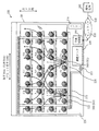
図6は、本実施の形態に係る植物工場装置102のブロック構成及びパレット150の移動を示す正面図であり、下部機器収納部120については内部の構成を模式的に表している図である。
Embodiment 3 FIG.
In the present embodiment, differences from the first embodiment and the second embodiment will be mainly described.
FIG. 6 is a front view showing the block configuration of the
本実施の形態では、実施の形態1及び実施の形態2で説明した機能構成と同様の機能構成については、同一の符号を付し、その説明を省略する。
図6を用いて、本実施の形態に係る植物工場装置102について説明する。
In the present embodiment, the same functional configuration as that described in the first embodiment and the second embodiment is denoted by the same reference numeral, and the description thereof is omitted.
The
本実施の形態に係る植物工場装置102は、各棚220a,220b,220c,220dにそれぞれ養液パン330a,330b,330c,330dを備える。
パレット150が下方から移動してくる位置(P7,P11,P15)と、パレット150が通過する位置(P19,P20,P1)とは、養液パン330を設置することはできないが、それ以外の位置に養液パンを設置することができる。
The
The position where the
また、このとき、棚220a,220b,220cは、左右方向の移動方向側の端部に実施の形態2で説明したパレット傾斜機構160を設置するのが好ましい。つまり、P6,P10,P14の位置にパレット傾斜機構160を設置するのが好ましい。
At this time, the
ただし、全ての棚220にパレット傾斜機構160を備えている必要はない。例えば、P6,P14の位置のみにパレット傾斜機構160を設置しても、養液を調節する効果がある。
However, it is not necessary that all the shelves 220 include the
以上のように、本実施の形態に係る植物工場装置102よれば、各段に養液パンを設置しているので、どの段も同様に農産物は養液パンより養分を吸収する事ができ、よりパレットの育成環境の均一化を図ることができる。
As mentioned above, according to the
実施の形態4.
本実施の形態について、主に実施の形態1との差異を説明する。
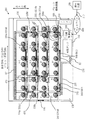
図7は、本実施の形態に係る植物工場装置103の斜視図である。
Embodiment 4 FIG.
In the present embodiment, differences from the first embodiment will be mainly described.
FIG. 7 is a perspective view of the
本実施の形態では、実施の形態1で説明した機能構成と同様の機能構成については、同一の符号を付し、その説明を省略する。
図7を用いて、本実施の形態に係る植物工場装置103について説明する。
In the present embodiment, the same functional configuration as that described in the first embodiment is denoted by the same reference numeral, and the description thereof is omitted.
The
植物工場装置103では、密閉型自動開閉扉140が図1とは反対側に記載されている。密閉型自動開閉扉140が設けられている外郭ケース110の側面をケース側面Aとする。また、外郭ケース110の前面をケース前面とし、ケース前面に対向する面はケース後面であるものとする。
密閉型自動開閉扉140が閉じられた状態では、ケース側面Aの内面は凹凸のない平面状であるものとする。
In the
In the state where the closed automatic opening /
植物工場装置103は、可動制御部300によりパレット150aの移動を完全に停止した状態で使用するものである。つまり、植物工場装置103では、パレット150aが移動しない。
The
植物工場装置103では、パレット150aがすき間無く配置されている。パレット150aは、複数の棚220の各棚に所定数(図7では、8個)配置されている。複数の棚220の各棚220は、パレット150aがすき間なく配置され、外郭ケース110の内部は、すき間なく配置された連続するパレット150aにより複数の栽培室700(700a〜700d)(空間領域)に仕切られる。この各栽培室700は、密閉されている。
In the
本実施の形態に係る植物工場装置103は、実施の形態1で説明した植物工場装置100を用いて、実現することができる。植物工場装置103のパレット150aの可動制御を停止し、パレット150aをすき間無く並べることにより、4つの密閉空間である栽培室700を得ることができる。
The
パレット150は、周縁に環状に渡ってパッキン152が設けられている。パレット150aのパレット短手方向の両側の側部のパッキン152は、隣のパレット150aの側部のパッキン152と密着する。
The
外郭ケース110の左右方向の一方の側面(ケース側面A)と当接するパレット150aのパッキン152は、外郭ケース110のケース側面Aの内面と密着する。
外郭ケース110の左右方向の他方の側面の内側には、後述する環境調整機器を収納する側部機器収納部122が設けられる。側部機器収納部122の内側の面と当接するパレット150aのパッキン152は、側部機器収納部122の内側の面と密着する。
The packing 152 of the
On the inner side of the other side surface of the
パレット150aのパレット長手方向の両側の端部のパッキン152は、一方の端部のパッキン152が外郭ケース110のケース前面の内面と密着するとともに、他方の端部のパッキン152がケース後面の内面と密着する。
以上のように、すき間無く並べられたパレット150aにより、密閉された栽培室700a〜700dを得ることができる。
The packing 152 at both ends of the
As described above, sealed cultivation rooms 700a to 700d can be obtained by the
4つの栽培室700には、環境を調整するためそれぞれ環境調整機器が必要となる。それぞれの環境調整機器を配置するために、外郭ケース110の左右方向の他方の側面内側に側部機器収納部122を設ける。
Each of the four cultivation rooms 700 requires an environmental adjustment device in order to adjust the environment. In order to arrange each environmental adjustment device, a side device storage portion 122 is provided inside the other side surface of the
側部機器収納部122に配置した各栽培室700用の環境調整機器による環境の調整により、4つの異なる環境の栽培室700を得ることができる。複数の栽培室700では、例えば、栽培環境の異なる4種類の植物400,401,402,403を栽培することができる。
By adjusting the environment with the environment adjusting device for each cultivation room 700 arranged in the side device storage part 122, the cultivation rooms 700 having four different environments can be obtained. In the plurality of cultivation rooms 700, for example, four types of
以上のように、本実施の形態に係る植物工場装置103によれば、パレットが自動で循環する構造の完全密閉人工光型植物工場装置において、装置内部を循環するパレットを停止することにより、別の用途にも使用することができる。
As described above, according to the
パレットの横(パレット短手方向)の長さの合計が、植物工場装置内部の内側の長手方向の長さと略同じ寸法に予め設計する。また、パレットの縦(パレット長手方向)の長さを植物工場装置の内部の内側の奥行き(短手方向)の長さの寸法と略同じになるように予め設計する。これにより、各棚220同士の間の空間領域を連結されたパレットにより密閉された空間とし、独立した栽培室として用いることができる。 The total length of the side of the pallet (pallet short direction) is designed in advance to be approximately the same as the length in the longitudinal direction inside the plant factory apparatus. The length of the pallet (pallet longitudinal direction) is designed in advance so as to be substantially the same as the length of the inner depth (short direction) inside the plant factory apparatus. Thereby, the space area | region between each shelf 220 can be made into the space sealed with the connected pallet, and can be used as an independent cultivation room.
栽培環境を栽培室ごとに異なるものとするために、光合成を促進するLEDライト、温度・湿度を制御するエアコン、CO2濃度を制御するCO2濃度コントローラー、風量を制御する空気攪拌機は、各栽培室毎に配置する。また、これらの環境調整機器の制御も各栽培室(各段)(パレットにより密閉された空間)毎に実施できる配置構造とする。 LED lights that promote photosynthesis, air conditioners that control temperature and humidity, CO2 concentration controllers that control CO2 concentration, and air stirrers that control air volume are different for each cultivation room in order to make the cultivation environment different for each cultivation room. To place. Moreover, it is set as the arrangement | positioning structure which can also implement control of these environmental adjustment apparatuses for every cultivation room (each stage) (space sealed with the pallet).
以上のように、本実施の形態に係る植物工場装置103によれば、同じひとつの完全密閉人工光型植物工場装置内部を用いて、栽培に必要な環境条件(光合成を促進するLEDライト、温度・湿度を制御するエアコン、CO2濃度を制御するCO2濃度コントローラー、風量を制御する空気攪拌機の制御)の異なる空間が提供可能となり、例えばレタスとトマトなど異なる農産物を同一の完全密閉人工光型植物工場装置で育成することを実現できる。
As described above, according to the
以上、本発明の実施の形態について説明したが、これらの実施の形態のうち、2つ以上を組み合わせて実施しても構わない。あるいは、これらの実施の形態のうち、1つを部分的に実施しても構わない。あるいは、これらの実施の形態のうち、2つ以上を部分的に組み合わせて実施しても構わない。なお、本発明は、これらの実施の形態に限定されるものではなく、必要に応じて種々の変更が可能である。 As mentioned above, although embodiment of this invention was described, you may implement in combination of 2 or more among these embodiment. Alternatively, one of these embodiments may be partially implemented. Alternatively, two or more of these embodiments may be partially combined. In addition, this invention is not limited to these embodiment, A various change is possible as needed.
100,101,102,103 植物工場装置、110 外郭ケース、111 枠組み部、112 カバー部、120 下部機器収納部、121 上部機器収納部、122 側部機器収納部、140 密閉型自動開閉扉、150 パレット、151 苗ポット用開口、152 パッキン、160 パレット傾斜機構、161 パレット傾斜部、220 棚、221 水平移動機構、225 枠、230 上下移動機構、240 下方移動機構、300 可動制御部、310 エアコン、320 液肥タンク、322 養液パイプ、323 開閉バルブ、330 養液パン、360 空気攪拌機、361 空気吹き出し口、371 天面LEDライト、372 各段LEDライト、400,401,402,403 植物、500 端末装置、510 制御命令、600 ネットワーク、700 栽培室。 100, 101, 102, 103 Plant factory equipment, 110 Outer case, 111 Frame part, 112 Cover part, 120 Lower equipment storage part, 121 Upper equipment storage part, 122 Side equipment storage part, 140 Sealed automatic opening / closing door, 150 Pallet, 151 seedling pot opening, 152 packing, 160 pallet tilting mechanism, 161 pallet tilting part, 220 shelf, 221 horizontal movement mechanism, 225 frame, 230 vertical movement mechanism, 240 downward movement mechanism, 300 movable control part, 310 air conditioner, 320 Liquid fertilizer tank, 322 Nutrient solution pipe, 323 Open / close valve, 330 Nutrient solution pan, 360 Air stirrer, 361 Air outlet, 371 Top LED light, 372 LED light on each stage, 400, 401, 402, 403 Plant, 500 Terminal Device, 510 control instructions, 00 network, 700 cultivation room.
Claims (13)
制御を受けることによって、前記パレットを、前記パレットが配置された棚の長手方向に移動させるとともに、前記パレットを上下に位置する2つの棚の一方の棚から他方の棚に移動させるパレット移動機構と、
前記パレット移動機構に対する前記制御によって、前記パレットを停止状態から移動させ、移動状態から停止させることを繰り返す制御部と
を備えることを特徴とする植物工場装置。 An outer case that houses therein a plurality of longitudinal shelves arranged at predetermined intervals in the vertical direction and a pallet on which plants are planted and at least one pallet arranged on at least one of the plurality of shelves. In a plant factory apparatus for cultivating a plant planted on the pallet under a controlled cultivation environment inside the outer case,
A pallet moving mechanism that moves the pallet in the longitudinal direction of the shelf on which the pallet is arranged and moves the pallet from one shelf to the other shelf on the top and bottom by receiving control. ,
A plant factory apparatus comprising: a control unit that repeatedly moves the pallet from the stopped state and stops the pallet from the moving state by the control of the pallet moving mechanism.
前記パレット移動機構に対する前記制御によって、前記パレットを間歇的に移動させることで、前記複数の棚のいずれかの棚の所定の位置から移動を始め、前記複数の棚の全ての棚を移動して前記所定の位置に戻る循環動作を前記パレットにさせることを特徴とする請求項1に記載の植物工場装置。 The controller is
By moving the pallet intermittently by the control on the pallet moving mechanism, the movement starts from a predetermined position of any of the plurality of shelves, and all the shelves of the plurality of shelves are moved. The plant factory apparatus according to claim 1, wherein the pallet is caused to circulate back to the predetermined position.
前記複数の棚の少なくともいずれかに備えられた養液パンであって、当該棚に配置されている前記パレットに植えられた植物に養液を供給する養液パンを備えることを特徴とする請求項1または2に記載の植物工場装置。 The plant factory device is:
A nutrient solution pan provided on at least one of the plurality of shelves, the nutrient solution pan supplying a nutrient solution to a plant planted on the pallet disposed on the shelf. Item 3. The plant factory apparatus according to item 1 or 2.
前記養液パンが備えられた棚である養液棚に設置され、前記パレット移動機構により前記パレットが前記養液棚から前記養液棚の上方の棚に移動する場合に、前記パレットを傾斜させて前記養液パンから供給される養液の液切りをするパレット傾斜機構を備えることを特徴とする請求項3に記載の植物工場装置。 The plant factory device is:
When the pallet is moved from the nutrient solution shelf to the shelf above the nutrient solution shelf by the pallet moving mechanism, the pallet is tilted. The plant factory device according to claim 3, further comprising a pallet tilting mechanism for draining the nutrient solution supplied from the nutrient solution pan.
前記複数の棚のうち最下段の棚の下方に設置された空気攪拌機であって、前記最下段の棚の下方に形成された吹き出し口から上方に向けて空気を吹き出すことにより、外郭ケースの内部の空気を攪拌する空気攪拌機を備え、
前記空気攪拌機は、
前記最下段の棚により形成される面の法線方向から所定の角度の範囲内に向けて、前記吹き出し口から空気を吹き出すことを特徴とする請求項1〜4のいずれかに記載の植物工場装置。 The plant factory device is:
An air stirrer installed below a lowermost shelf among the plurality of shelves, wherein air is blown upward from a blowout port formed below the lowermost shelf, so that the inside of the outer case Equipped with an air stirrer to stir the air of
The air stirrer
The plant factory according to any one of claims 1 to 4, wherein air is blown out from the blowing port toward a predetermined angle range from a normal direction of a surface formed by the bottom shelf. apparatus.
前記最下段の棚により形成される面の法線方向から45度の範囲内に向けて、前記吹き出し口から空気を吹き出すことを特徴とする請求項5に記載の植物工場装置。 The air stirrer
The plant factory apparatus according to claim 5, wherein air is blown out from the outlet in a range of 45 degrees from a normal direction of a surface formed by the bottom shelf.
前記複数の棚のいずれかの棚の端部近傍に開閉扉を備えることを特徴とする請求項1〜6のいずれかに記載の植物工場装置。 The outer case is
The plant factory apparatus according to any one of claims 1 to 6, further comprising an opening / closing door in the vicinity of an end of any one of the plurality of shelves.
前記パレットの移動と停止とを定期と不定期とのいずれかで繰り返させることを特徴とする請求項1〜7のいずれかに記載の植物工場装置。 The controller is
The plant factory apparatus according to any one of claims 1 to 7, wherein the movement and stoppage of the pallet are repeated regularly or irregularly.
前記複数の棚の各棚は、
前記制御部が前記パレットを停止した場合に、前記パレットがすき間なく配置され、
前記外郭ケースの内部は、前記パレットがすき間なく配置された各棚により複数の空間領域に仕切られることを特徴とする請求項1に記載の植物工場装置。 A predetermined number of the pallets are arranged on each of the plurality of shelves,
Each shelf of the plurality of shelves
When the control unit stops the pallet, the pallet is arranged without gaps,
The plant factory apparatus according to claim 1, wherein the inside of the outer case is partitioned into a plurality of space regions by shelves in which the pallets are arranged without gaps.
前記パレットを停止状態から移動させ、移動状態から停止させることを繰り返すパレット移動制御工程を備えることを特徴とするパレット移動制御方法。 An outer case that houses therein a plurality of longitudinal shelves arranged at predetermined intervals in the vertical direction and a pallet on which plants are planted and at least one pallet arranged on at least one of the plurality of shelves. In a pallet movement control method of a plant factory apparatus for cultivating a plant planted on the pallet under a controlled environment inside the outer case,
A pallet movement control method comprising a pallet movement control step of repeatedly moving the pallet from a stopped state and stopping the pallet from the moved state.
前記パレットを、前記パレットが配置された棚の長手方向へ移動させるとともに、上下に位置する2つの棚の一方の棚から他方の棚へ移動させることを特徴とする請求項11に記載のパレット移動制御方法。 The pallet movement control step includes
The pallet movement according to claim 11, wherein the pallet is moved in the longitudinal direction of the shelf on which the pallet is arranged, and is moved from one shelf to the other shelf of two shelves positioned above and below. Control method.
前記パレットを間歇的に移動させることで、複数の棚のいずれかの棚の所定の位置から移動を始め、前記複数の棚の全ての棚を移動して前記所定の位置に戻る循環動作を前記パレットにさせることを特徴とする請求項12に記載のパレット移動制御方法。
The pallet movement control step includes
By moving the pallet intermittently, the circulation operation starts from a predetermined position of any one of the plurality of shelves, moves all the shelves of the plurality of shelves, and returns to the predetermined position. The pallet movement control method according to claim 12, wherein the pallet is moved to a pallet.
Priority Applications (3)
| Application Number | Priority Date | Filing Date | Title |
|---|---|---|---|
| JP2012226299A JP2016000002A (en) | 2012-10-11 | 2012-10-11 | Plant factory apparatus and pallet movement control method |
| PCT/JP2013/075758 WO2014057800A1 (en) | 2012-10-11 | 2013-09-24 | Plant factory device and pallet movement control method |
| TW102136478A TW201424577A (en) | 2012-10-11 | 2013-10-09 | Plant factory apparatus and pallet movement control method |
Applications Claiming Priority (1)
| Application Number | Priority Date | Filing Date | Title |
|---|---|---|---|
| JP2012226299A JP2016000002A (en) | 2012-10-11 | 2012-10-11 | Plant factory apparatus and pallet movement control method |
Publications (1)
| Publication Number | Publication Date |
|---|---|
| JP2016000002A true JP2016000002A (en) | 2016-01-07 |
Family
ID=50477271
Family Applications (1)
| Application Number | Title | Priority Date | Filing Date |
|---|---|---|---|
| JP2012226299A Pending JP2016000002A (en) | 2012-10-11 | 2012-10-11 | Plant factory apparatus and pallet movement control method |
Country Status (3)
| Country | Link |
|---|---|
| JP (1) | JP2016000002A (en) |
| TW (1) | TW201424577A (en) |
| WO (1) | WO2014057800A1 (en) |
Cited By (6)
| Publication number | Priority date | Publication date | Assignee | Title |
|---|---|---|---|---|
| JP2017192335A (en) * | 2016-04-20 | 2017-10-26 | 司ゴム電材株式会社 | Hydroponic shelf |
| JP2019170391A (en) * | 2019-06-10 | 2019-10-10 | 司ゴム電材株式会社 | Hydroponics shelf |
| WO2021182221A1 (en) * | 2020-03-10 | 2021-09-16 | 株式会社ファームシップ | Cultivation device |
| WO2022038882A1 (en) * | 2020-08-17 | 2022-02-24 | 株式会社ファームシップ | Cultivation apparatus and cultivation facility |
| JP7403442B2 (en) | 2018-04-23 | 2023-12-22 | 株式会社プランテックス | cultivation equipment |
| JP7423637B2 (en) | 2019-01-09 | 2024-01-29 | オカド・イノベーション・リミテッド | Growth system and method |
Families Citing this family (4)
| Publication number | Priority date | Publication date | Assignee | Title |
|---|---|---|---|---|
| CN104604598B (en) * | 2015-01-19 | 2017-06-13 | 同济大学 | A kind of adjusting transmission of light rate automatically moves Tridimensional seedling bed system |
| HK1203026A2 (en) * | 2015-06-26 | 2015-10-09 | 馮志華 | Vertical tower for organic farming |
| WO2019030428A1 (en) * | 2017-08-07 | 2019-02-14 | Netled Oy | Method and arrangement for growing plants on multilayer principle |
| CN110637647A (en) * | 2019-09-18 | 2020-01-03 | 福建永德吉灯业股份有限公司 | Artificial light plant factory circulating mobile cultivation method and plant building |
Family Cites Families (7)
| Publication number | Priority date | Publication date | Assignee | Title |
|---|---|---|---|---|
| JPS51145743A (en) * | 1975-06-11 | 1976-12-14 | Kawasaki Heavy Ind Ltd | Tower type farming device |
| JPS58198232A (en) * | 1982-05-14 | 1983-11-18 | 伊東 璋 | Hydropontic apparatus |
| JPS62126919A (en) * | 1985-11-26 | 1987-06-09 | 諏訪 賢太郎 | Apparatus for growing plant such as vegetables |
| JP3026502U (en) * | 1995-12-29 | 1996-07-16 | 會田 文男 | Cultivation tray arranged in a greenhouse and means for moving / circulating the cultivation tray |
| JP3045030U (en) * | 1997-07-02 | 1998-01-23 | 至 六反田 | Rotary sunshine |
| JP2000069858A (en) * | 1998-07-16 | 2000-03-07 | Satoshi Takano | Method for culturing plant in green house and apparatus therefor |
| JP2001095404A (en) * | 1999-09-27 | 2001-04-10 | Kaise Rika Kk | Method for automated culture of plant and apparatus for automated culture |
-
2012
- 2012-10-11 JP JP2012226299A patent/JP2016000002A/en active Pending
-
2013
- 2013-09-24 WO PCT/JP2013/075758 patent/WO2014057800A1/en active Application Filing
- 2013-10-09 TW TW102136478A patent/TW201424577A/en unknown
Cited By (7)
| Publication number | Priority date | Publication date | Assignee | Title |
|---|---|---|---|---|
| JP2017192335A (en) * | 2016-04-20 | 2017-10-26 | 司ゴム電材株式会社 | Hydroponic shelf |
| JP7403442B2 (en) | 2018-04-23 | 2023-12-22 | 株式会社プランテックス | cultivation equipment |
| JP7423637B2 (en) | 2019-01-09 | 2024-01-29 | オカド・イノベーション・リミテッド | Growth system and method |
| JP2019170391A (en) * | 2019-06-10 | 2019-10-10 | 司ゴム電材株式会社 | Hydroponics shelf |
| WO2021182221A1 (en) * | 2020-03-10 | 2021-09-16 | 株式会社ファームシップ | Cultivation device |
| WO2022038882A1 (en) * | 2020-08-17 | 2022-02-24 | 株式会社ファームシップ | Cultivation apparatus and cultivation facility |
| JP2022033467A (en) * | 2020-08-17 | 2022-03-02 | スペースファームテクノロジー株式会社 | Cultivation device and cultivation installation |
Also Published As
| Publication number | Publication date |
|---|---|
| WO2014057800A1 (en) | 2014-04-17 |
| TW201424577A (en) | 2014-07-01 |
Similar Documents
| Publication | Publication Date | Title |
|---|---|---|
| WO2014057800A1 (en) | Plant factory device and pallet movement control method | |
| KR101719400B1 (en) | Plants cultivation device with air purification function | |
| US10098287B2 (en) | System and method for cultivating plants | |
| KR101986139B1 (en) | Smart farm cultivation system | |
| JP5467438B2 (en) | Plant cultivation facility | |
| KR101009461B1 (en) | Apparatus for hydroponics cultivation | |
| KR20180074665A (en) | High density horticulture growing system, method and apparatus | |
| CN107683086A (en) | Cultivating seedlings device and method for cultivating seedlings | |
| JP5735749B2 (en) | Plant growing machine | |
| JP2013034402A (en) | Hydroponic device | |
| KR101219787B1 (en) | APPARATUS FOR CULTIVATING PlANT OF VERTICAL TYPE | |
| KR20180057298A (en) | Device for hydroponics | |
| KR20170050428A (en) | Liquid level control modules and apparatus including the same | |
| US20130340338A1 (en) | Hydroponic Device for Liquid Supply | |
| JP2017201929A (en) | Multistage raising seedling apparatus | |
| JPH10215701A (en) | Plant factory | |
| KR20200002432A (en) | Device for cultivating plants | |
| KR101582388B1 (en) | Plant Cultivation Equipment | |
| KR102091765B1 (en) | Container Farm using Horizontal Circulation of Vertical Growing Unit | |
| WO2011067548A1 (en) | Apparatus for growing plants | |
| JP2000023574A (en) | Plant factory | |
| KR101524686B1 (en) | Mushroom growing apparatus for controling temperature and humidity automatically | |
| US20200245567A1 (en) | Tray for growing agricultural products | |
| KR102444908B1 (en) | Circulation type cultivation device | |
| KR101869777B1 (en) | Apparatus of indoor hydroponic system for ginseng |