JP2015511898A - Printing method for reducing printer artifacts - Google Patents
Printing method for reducing printer artifacts Download PDFInfo
- Publication number
- JP2015511898A JP2015511898A JP2015500587A JP2015500587A JP2015511898A JP 2015511898 A JP2015511898 A JP 2015511898A JP 2015500587 A JP2015500587 A JP 2015500587A JP 2015500587 A JP2015500587 A JP 2015500587A JP 2015511898 A JP2015511898 A JP 2015511898A
- Authority
- JP
- Japan
- Prior art keywords
- roller
- heating
- print medium
- medium
- printing
- Prior art date
- Legal status (The legal status is an assumption and is not a legal conclusion. Google has not performed a legal analysis and makes no representation as to the accuracy of the status listed.)
- Pending
Links
Images


Classifications
-
- B—PERFORMING OPERATIONS; TRANSPORTING
- B41—PRINTING; LINING MACHINES; TYPEWRITERS; STAMPS
- B41J—TYPEWRITERS; SELECTIVE PRINTING MECHANISMS, i.e. MECHANISMS PRINTING OTHERWISE THAN FROM A FORME; CORRECTION OF TYPOGRAPHICAL ERRORS
- B41J2/00—Typewriters or selective printing mechanisms characterised by the printing or marking process for which they are designed
- B41J2/315—Typewriters or selective printing mechanisms characterised by the printing or marking process for which they are designed characterised by selective application of heat to a heat sensitive printing or impression-transfer material
-
- B—PERFORMING OPERATIONS; TRANSPORTING
- B41—PRINTING; LINING MACHINES; TYPEWRITERS; STAMPS
- B41M—PRINTING, DUPLICATING, MARKING, OR COPYING PROCESSES; COLOUR PRINTING
- B41M3/00—Printing processes to produce particular kinds of printed work, e.g. patterns
- B41M3/008—Sequential or multiple printing, e.g. on previously printed background; Mirror printing; Recto-verso printing; using a combination of different printing techniques; Printing of patterns visible in reflection and by transparency; by superposing printed artifacts
-
- B—PERFORMING OPERATIONS; TRANSPORTING
- B41—PRINTING; LINING MACHINES; TYPEWRITERS; STAMPS
- B41J—TYPEWRITERS; SELECTIVE PRINTING MECHANISMS, i.e. MECHANISMS PRINTING OTHERWISE THAN FROM A FORME; CORRECTION OF TYPOGRAPHICAL ERRORS
- B41J11/00—Devices or arrangements of selective printing mechanisms, e.g. ink-jet printers or thermal printers, for supporting or handling copy material in sheet or web form
- B41J11/0005—Curl smoothing, i.e. smoothing down corrugated printing material, e.g. by pressing means acting on wrinkled printing material
-
- B—PERFORMING OPERATIONS; TRANSPORTING
- B41—PRINTING; LINING MACHINES; TYPEWRITERS; STAMPS
- B41J—TYPEWRITERS; SELECTIVE PRINTING MECHANISMS, i.e. MECHANISMS PRINTING OTHERWISE THAN FROM A FORME; CORRECTION OF TYPOGRAPHICAL ERRORS
- B41J3/00—Typewriters or selective printing or marking mechanisms characterised by the purpose for which they are constructed
- B41J3/60—Typewriters or selective printing or marking mechanisms characterised by the purpose for which they are constructed for printing on both faces of the printing material
-
- B—PERFORMING OPERATIONS; TRANSPORTING
- B41—PRINTING; LINING MACHINES; TYPEWRITERS; STAMPS
- B41M—PRINTING, DUPLICATING, MARKING, OR COPYING PROCESSES; COLOUR PRINTING
- B41M5/00—Duplicating or marking methods; Sheet materials for use therein
- B41M5/0011—Pre-treatment or treatment during printing of the recording material, e.g. heating, irradiating
-
- B—PERFORMING OPERATIONS; TRANSPORTING
- B41—PRINTING; LINING MACHINES; TYPEWRITERS; STAMPS
- B41M—PRINTING, DUPLICATING, MARKING, OR COPYING PROCESSES; COLOUR PRINTING
- B41M5/00—Duplicating or marking methods; Sheet materials for use therein
- B41M5/26—Thermography ; Marking by high energetic means, e.g. laser otherwise than by burning, and characterised by the material used
- B41M5/382—Contact thermal transfer or sublimation processes
- B41M5/38207—Contact thermal transfer or sublimation processes characterised by aspects not provided for in groups B41M5/385 - B41M5/395
- B41M5/38221—Apparatus features
-
- B—PERFORMING OPERATIONS; TRANSPORTING
- B41—PRINTING; LINING MACHINES; TYPEWRITERS; STAMPS
- B41M—PRINTING, DUPLICATING, MARKING, OR COPYING PROCESSES; COLOUR PRINTING
- B41M7/00—After-treatment of prints, e.g. heating, irradiating, setting of the ink, protection of the printed stock
Abstract
印刷方法は、印刷のためのプリントヘッドおよびローラを含む。印刷ジョブの1ページが印刷されると、印刷媒体の印刷されなかった側にへこみができる。印刷媒体を加熱して、印刷されなかった側に印刷する前にそのへこみを減少させる。The printing method includes a print head and a roller for printing. When one page of the print job is printed, a dent is formed on the side of the print medium that has not been printed. The print medium is heated to reduce its dent before printing on the non-printed side.
Description
本発明は、感熱印刷に関し、詳細には、印刷濃度のばらつきを減少させるために、キャプスタンローラに曝される染料受容層の表面に熱処理を施すことに関する。 The present invention relates to thermal printing and, in particular, to heat treating the surface of a dye-receiving layer that is exposed to a capstan roller to reduce print density variation.
染料拡散感熱転写プリンタにおいて、制御可能に紙を動かし牽引力を維持してカラーパスの間に厳密に画像を位置合わせするために、急激な凹凸が付いた駆動ローラ、およびそれと対になる紙と駆動ローラの間に荷重を掛けるピンチローラがよく使用されることが、周知の方法である。このタイプの駆動システムでは、片面だけの印刷すなわちシンプレックス印刷の場合、印刷された紙上に画像のアーチファクトは全くできない。というのも、急激な凹凸が付いた駆動ローラは、紙の印刷側には接触しないからである。両面印刷すなわちデュープレックス印刷の場合は、急激な凹凸が付いた駆動ローラが印刷シートの両面に接触しなければならないので、この方法では問題がある。両面印刷すなわちデュープレックス印刷の場合、駆動ローラの急激な凹凸が付いた表面に接触する紙の表面には、急激な凹凸がある表面によって傷がつくことがある。この傷ついた紙の表面には染料が容易には転写されず、その結果、駆動ローラの急激な凹凸に接触した領域と接触しなかった領域との間で目に見える濃度のばらつきが生じる。 In a dye diffusion thermal transfer printer, a drive roller with a steep ruggedness and a pair of paper and drive to controllably move the paper and maintain traction and precisely align the image during the color pass It is a well-known method that a pinch roller that applies a load between the rollers is often used. With this type of drive system, in the case of single-sided printing, ie simplex printing, there is no image artifacts on the printed paper. This is because the drive roller with sharp irregularities does not contact the printing side of the paper. In the case of double-sided printing, that is, duplex printing, there is a problem with this method because the driving roller with sharp irregularities must come into contact with both sides of the printing sheet. In the case of duplex printing, that is, duplex printing, the surface of the paper that contacts the surface with the sudden irregularities of the drive roller may be damaged by the surface with sudden irregularities. The dye is not easily transferred to the surface of the damaged paper, and as a result, there is a visible density variation between the area that is in contact with the sharp irregularities of the drive roller and the area that is not in contact.
さらに、染料拡散感熱転写プリンタのファームウェアに、ページ全体にわたる濃度変化および/またはページの下方向の濃度変化を修正する補償アルゴリズムを組み込むのが一般的な方法である。プリンタハードウェアまたはプリンタファームウェアには限界があり、したがって補償アルゴリズムが駆動ローラによって生じた印刷のアーチファクトを完全には補償できない恐れがある。こうした限界があるので、媒体に接触する凹凸付きの駆動ローラにより生じる印刷媒体表面のずれ(deviation)を最小限に抑えることが重要となる。 Further, it is common practice to incorporate a compensation algorithm in the dye diffusion thermal transfer printer firmware that corrects density changes across the page and / or down the page. The printer hardware or printer firmware has limitations, so the compensation algorithm may not be able to fully compensate for printing artifacts caused by the drive roller. Because of these limitations, it is important to minimize the deviation of the print media surface caused by the uneven drive roller that contacts the media.
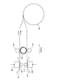
図1に関して、両面すなわちデュープレックスの染料拡散感熱転写印刷の場合、2つの感熱プリントヘッド102、109を使用するのが一般的な方法である。まず、ロール106のモータ駆動装置(図示せず)と協働して、駆動ローラ(またはキャプスタンローラ)105とピンチローラ104によって、巻かれた印刷媒体106をプラテンローラ112と一方の感熱プリントヘッド102の間に動かし(印刷媒体の移動経路は実線で図示されている)、染料ドナー101を使用して印刷媒体の片面であるサイドAに印刷する。駆動ローラ105とピンチローラ104の間に動かされた印刷媒体ロール106から受け取られたある長さの印刷媒体は、サイドBを露出して駆動ローラの表面の凹凸に接触し、それによって後で印刷されるサイドBの表面が傷つけられる。サイドBの表面が、凹凸付きの駆動ローラ105によって傷つけられ、サイドBの表面の最外層またはより多くの層に穴が開けられ、へこみが形成され、ピットが形成され、または圧痕が形成される。次いで、印刷媒体は、ロール106のモータ駆動装置と協働して、駆動ローラ105とピンチローラ104の反転によって、紙の前縁が供給ロール106に向けて後退するように再位置決めされ、次いで、破線によって図示される経路へと方向転換される。巻かれた印刷媒体106は、ロール106のモータ駆動装置と協働して、駆動ローラ(またはキャプスタンローラ)105とピンチローラ107によって、プラテンローラ111と第2の感熱プリントヘッド109の間に動かされる。次いで、印刷媒体の印刷されていない面であるサイドBが染料ドナー110を使用して印刷される。
With respect to FIG. 1, for double sided or duplex dye diffusion thermal transfer printing, it is common practice to use two thermal print heads 102,109. First, in cooperation with a motor driving device (not shown) for the
本特許出願の好ましい実施形態は、印刷方法であって、プリンタ内に両面媒体を受けること、媒体の第1の面に印刷すること、第1の面の印刷後、媒体の第2の面を平坦にすること、および媒体がプリンタ内に留まっている間に第2の面に印刷することを含む方法を含む。平坦にすることは、媒体を加熱面に押しつけることにより媒体の第2の面を加熱することによって行われ、加熱ローラとして実施され得る。複数のローラが使用可能であり、そこにおいて、複数のローラの少なくとも1つが加熱され、その加熱ローラに印刷媒体が押しつけられる。加熱ローラは、熱を発生させるのにローラに電流を流す電子写真プリンタの定着器の場合と同様に実施され得る。 A preferred embodiment of the present patent application is a printing method for receiving a double-sided medium in a printer, printing on a first side of the medium, printing a first side, and then printing a second side of the medium. Including a method comprising flattening and printing on the second side while the media remains in the printer. Flattening is performed by heating the second side of the media by pressing the media against the heating surface and can be implemented as a heating roller. A plurality of rollers can be used, where at least one of the plurality of rollers is heated and the print medium is pressed against the heated roller. The heated roller can be implemented in the same manner as in the case of an electrophotographic printer fuser that passes a current through the roller to generate heat.
本発明の他の好ましい実施形態は、デュープレックス印刷媒体の第1の面に押しつけられる凹凸付きローラを使用して印刷媒体をプリンタに引き込むことを含む、プリンタ内にデュープレックス印刷媒体を受けることによる印刷方法を含む。印刷媒体の第2の面が印刷され、それには感熱プリントヘッドを使用することが含まれる。デュープレックス印刷媒体の第2の面の印刷ステップの後にデュープレックス印刷媒体の第1の面を平坦にすることにより、デュープレックス印刷媒体の第1の面にある圧痕の寸法が減少される。へこみの減少後、デュープレックス印刷媒体の第1の面が印刷される。 Another preferred embodiment of the present invention is a method of printing by receiving a duplex print medium in a printer comprising drawing the print medium into the printer using a rugged roller that is pressed against the first side of the duplex print medium. including. A second side of the print medium is printed, which includes using a thermal printhead. By flattening the first side of the duplex print medium after the printing step of the second side of the duplex print medium, the size of the indentation on the first side of the duplex print medium is reduced. After the dent reduction, the first side of the duplex print medium is printed.
本発明の他の好ましい実施形態は、印刷媒体を、ピンチローラと凹凸付きキャプスタンローラの間に形成されるニップを通して引っ張ることを含む、印刷媒体を取り扱う方法を含む。そこにおいて、キャプスタンローラにより、複数の圧痕が片面上に形成されるので、印刷媒体の片面に対して感熱プリントヘッドによって施されるドナー染料を受ける印刷媒体の片面の性能が落ちる。印刷媒体の片面は、印刷媒体を引っ張るステップの後に印刷媒体の片面を加熱することにより平坦にされる。これは、ピンチローラと加熱ローラによって形成されるニップを通って印刷媒体を引っ張ることによって行われる。 Another preferred embodiment of the present invention includes a method of handling print media, including pulling the print media through a nip formed between a pinch roller and an uneven capstan roller. There, a plurality of indentations are formed on one side by the capstan roller, so that the performance of one side of the print medium that receives the donor dye applied by the thermal print head to one side of the print medium is degraded. One side of the print medium is flattened by heating one side of the print medium after the step of pulling the print medium. This is done by pulling the print medium through a nip formed by a pinch roller and a heating roller.
本発明の上記その他の態様および目的は、添付の図面と併せて以下の説明を読めばより明らかになり理解されるであろう。しかし、以下の説明は、本発明の好ましい実施形態およびその多数の特有の詳細を示すが、限定としてではなく例として与えられると理解されたい。例えば、上述の要約の説明は、その要素が互換可能でない個々の別々の実施形態を説明するようには意図されない。実際、特定の実施形態に関連するように説明される要素の多くは、他の説明される実施形態の要素と一緒に使用する、および場合によってはそれらと交換することができる。本発明の精神から逸脱することなく、本発明の範囲内で様々な変更および変形を行うことができ、本発明はそうした変形を全て包含する。以下の図面は、相対的寸法、角度関係、もしくは相対的位置に関していかなる精密な尺度にあわせて描かれておらず、実際の実施の互換性、置換もしくは表現に関する組み合わせの関係についても描かれていないものとする。 These and other aspects and objects of the present invention will become more apparent and understood by reading the following description in conjunction with the accompanying drawings. However, it is to be understood that the following description provides preferred embodiments of the invention and numerous specific details thereof, given by way of example and not limitation. For example, the above summary description is not intended to describe individual separate embodiments whose elements are not interchangeable. In fact, many of the elements described in connection with a particular embodiment can be used in conjunction with, and possibly interchanged with, elements of other described embodiments. Various changes and modifications may be made within the scope of the present invention without departing from the spirit thereof, and the invention includes all such modifications. The following drawings are not drawn to any precise scale with respect to relative dimensions, angular relationships, or relative positions, nor are they drawn to the actual implementation compatibility, substitutions or combinations of representations: Shall.
本発明の好ましい実施形態は、添付の図面と併せて以下に示される例示的な実施形態の詳細な説明を読めばより簡単に理解することができるであろう。 Preferred embodiments of the present invention will be more readily understood upon reading the detailed description of the exemplary embodiments presented below in conjunction with the accompanying drawings.
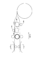
好ましい印刷方法およびその装置が本明細書に詳細に記載されており、図2に示されている。図1と共通する構成要素は、上述のように動作可能である。上述したように、印刷媒体のサイドAの印刷完了後、印刷媒体は、供給ロール106に向けて後退するときに圧力ローラ103aによって加熱ローラ108に押しつけられ、熱と圧力が相まって、サイドBの表面に駆動ローラ105によって残されたへこみ箇所の寸法が減少される。プリンタは、さらに、本明細書に記載されるのとは逆の順序でも動作可能であり、その場合、サイドBがはじめに印刷され、駆動ローラ105によって形成されたサイドAのへこみが圧力ローラ103bと加熱ローラ108の間で圧迫されることで減少される。図2には、加熱ローラ108と相まってニップを形成する圧力ローラ103aが示されている。ただし、必要に応じて、一緒にニップを形成するように圧力ローラ103aと圧力ローラ103bの両方を、加熱ローラ108に対してある位置まで、およびある位置から、移すことができる。加熱ローラは、加熱するのにローラに流れる電流を使用する、電子写真プリンタで使用される定着ローラに類似しており、または好ましい代替実施形態(図3A、3B)では、加熱デバイスは、2つの追加の感熱プリントヘッド208、および印刷媒体表面を平坦にすることが唯一の目的であるプラテンローラ203を備える。加熱デバイスは、図3Aに示されるようにまたは図3Bに示されるように配置される場合、本発明に従って印刷媒体を回復させるように動作することができる。
A preferred printing method and apparatus are described in detail herein and are shown in FIG. Components in common with FIG. 1 are operable as described above. As described above, after the printing on the side A of the printing medium is completed, the printing medium is pressed against the
図3Bを参照すると、上述したように印刷媒体のサイドAの印刷が完了した後、印刷媒体は、前述したように供給ロールに向けて後退し、次いで、破線で示される経路に沿って方向転換される。キャプスタンローラとピンチローラは、印刷媒体の長さがプリントヘッドより先まで延びるように、印刷媒体を、プリントヘッドとプラテンローラの間に動かす。これは、印刷媒体が、図面に示されるように、感熱印刷ステップの間、左から右に引っ張られるからである。この時点で、印刷媒体がプリントヘッドおよびプラテンローラより先まで延ばされており印刷のためにプリントヘッドの方に向かって引っ張られている間、圧力ローラ303bによって、印刷媒体は加熱ローラ308bに押しつけられ、熱と圧力が相まって、サイドBの表面に駆動ローラによって残されたへこみ箇所の寸法が減少する。プリンタは、さらに、サイドBがまず印刷され、駆動ローラによって形成されるサイドAのへこみが、サイドAの印刷前に、圧力ローラ303aと加熱ローラ308aの間における圧迫によって減少されるという、逆の順序でも動作可能である。 Referring to FIG. 3B, after printing of side A of the print media is completed as described above, the print media is retracted toward the supply roll as described above and then turned along the path indicated by the dashed line. Is done. The capstan roller and pinch roller move the print medium between the print head and the platen roller so that the length of the print medium extends beyond the print head. This is because the print media is pulled from left to right during the thermal printing step, as shown in the drawings. At this point, the print medium is pressed against the heating roller 308b by the pressure roller 303b while the print medium is extended beyond the print head and platen roller and pulled toward the print head for printing. The combination of heat and pressure reduces the size of the dents left by the drive roller on the surface of side B. The printer further has the reverse that side B is printed first, and the side A dent formed by the drive roller is reduced by compression between pressure roller 303a and heating roller 308a before printing of side A. It can also work in order.
上述した印刷動作の間、穴、へこみ、パーホレーションまたは圧痕が、印刷される側とは反対側にあるキャプスタンローラによって作り出されることが実験から分かっている。これらの穴は、外側染料受容層(DRL)にできた三日月形の圧痕である。媒体のタイプによっては、これらの穴は、DRLを穿通し、その結果、DRLにパーホレーションができることもある。DRLは、可撓性の層であり、したがって駆動ローラによって圧痕がつけられる、または穴が開けられることがある。DRLに駆動ローラによって圧痕がつけられるにせよ穴が開けられるにせよ、加熱ステップによってDRL表面が回復して染料ドナーを受容できるようになり、その結果、印刷品質が向上する。両面感熱プリンタ設計の中には、凹凸付き駆動ローラがないかたちで考えられているものもあることに留意されたい。そうではなくて、駆動ローラ上に急激な凹凸がないことにより失われた牽引力を補うために、ピンチローラに対する圧力を増加させた平坦な駆動ローラが使用される。圧力が増加することで、やはりまた、デュープレックス受容体にへこみまたは圧痕、すなわち「トラック」ができ、その結果、ページ全体にわたって濃度のばらつきが生じる恐れがある。本明細書に記載の本発明の実施形態は、これらのばらつきを修正する働きもする。 Experiments have shown that during the printing operation described above, holes, dents, perforations or indentations are created by a capstan roller on the side opposite the side to be printed. These holes are crescent-shaped indentations in the outer dye-receiving layer (DRL). Depending on the type of media, these holes may penetrate the DRL, resulting in perforation of the DRL. The DRL is a flexible layer and can therefore be indented or punctured by a drive roller. Whether the DRL is indented or pierced by a drive roller, the heating step restores the DRL surface to accept the dye donor, resulting in improved print quality. It should be noted that some double-sided thermal printer designs are considered in the absence of an uneven drive roller. Rather, a flat drive roller with increased pressure on the pinch roller is used to compensate for the traction lost due to the absence of sharp irregularities on the drive roller. Increasing the pressure can again create dents or indentations or “tracks” in the duplex receptor, which can result in density variations across the page. The embodiments of the invention described herein also serve to correct these variations.
図6を参照すると、図面には、本発明の好ましい一実施形態により企図された、デュープレックス受容構造体601における様々な層の厚さが示されている。他のデュープレックス受容体材料も、本発明の実施形態を使用すれば、同様に改善され得る。凹凸付き駆動ローラは、一般的に、その円筒表面から約25ミクロンの長さに延びる突出部を備える。
Referring to FIG. 6, the drawing shows the thickness of the various layers in
この傷つけられたDRL表面に印刷が施されると、キャプスタンローラに対応する領域の印刷濃度が、残りの印刷部分に見られる印刷濃度よりも薄くなる。これは、感熱印刷ステップで、意図した通りには穴に染料が満たされず、したがって、ハーフトーンの影響により目に見えてより薄い印刷濃度になる、という仮説がたてられた(また、顕微鏡の使用により観察された)。ボイドがある2軸配向されたポリプロピレンラミネートを含む両面感熱受容体(媒体)を、試験目的に、1回通過させた。1回通過させるということは、受容体が、印刷されずに、キャプスタンローラを1回通って引っ張られた、すなわち動かされたことを意味する。実験では、キャプスタンローラに曝される印刷されていないDRL表面上の熱処理の効果を評価した。熱処理は、電子写真の定着器のブレッドボードを使用して施された。このブレッドボードは、加熱ローラ108と圧力ローラ103aまたは103bによって形成されるエラストマニップであるニップ間で、一定圧力で、温度および線速度が変えられ得る。感圧媒体を使用して測定されたニップの幅は、5mmであった。この幅は、印刷媒体に沿って縦方向に測定され、印刷媒体が間にある状態でコンプライアント圧力ローラに対する加熱ローラの圧力によって形成される。より大きな直径の加熱ローラ、より大きな直径のコンプライアント圧力ローラ、またはどちらのローラもより適合するように作られている場合、圧力が増加するとニップの幅は増大する。ニップの幅が増大すると、印刷媒体に伝達される熱量が増加する。典型的な圧力ローラは、厚いシリコンゴム層を有し、外側層として薄いテフロン(登録商標)コーティングを有するスチールコアである。加熱ローラは、たいていの電子写真プリンタで使用されている定着ローラの設計と類似している。
When printing is performed on the damaged DRL surface, the print density in the area corresponding to the capstan roller becomes lighter than the print density found in the remaining print portion. It was hypothesized that the thermal printing step would not fill the hole with the dye as intended, and thus would result in a visibly lighter print density due to halftone effects (and also in the microscope). Observed by use). A double-sided thermal receptor (medium) comprising a biaxially oriented polypropylene laminate with voids was passed once for testing purposes. Passing once means that the receiver has been pulled or moved through the capstan roller once without being printed. In the experiment, the effect of heat treatment on the unprinted DRL surface exposed to the capstan roller was evaluated. The heat treatment was carried out using an electrophotographic fuser breadboard. This breadboard can be changed in temperature and linear velocity at a constant pressure between the nip which is an elastomer nip formed by the
プリンタ内で加熱されたキャプスタンローラに曝されたDRL側を試験することができるように、10フィートの各バリエーションが作られた。図4に示されるように観察結果を記録した。所定の温度および線速度の条件(例えば、150℃、70mm/秒)について、印刷媒体(受容体)をニップに2回および3回通した。出願人らは、10mmのニップの幅に媒体を曝すのと同等であるとして(受容体が加熱ステップの合間に冷えるので、不連続なやり方ではあるが)媒体を5mmニップに2回通し、15mmのニップの幅に曝すのと同等であるとして(上述のように不連続なやり方ではあるが)媒体を3回通すことを考えた。図5には、印刷媒体のキャプスタンローラにより傷ついた領域と印刷媒体のキャプスタンに接触しなかった部分のデルタL*(ΔL*)の違いが強調して示されている。L*は、明るさの任意の相対的な程度であり、図5のグラフに示されるL*の変化は、他の測定されたマグニチュードに対して相対的であると解釈されるべきである。マグニチュードは、写真濃度計を用いて測定される。熱処理(150℃、70mm/秒)を受けたサンプルは、より低いΔL*を示すことが認められ、すなわち、接触しなかった媒体とキャプスタンにより傷ついた媒体との間における目に見える違いが小さくなることが認められた。 Each variation of 10 feet was made so that the DRL side exposed to the heated capstan roller in the printer could be tested. The observation results were recorded as shown in FIG. For a given temperature and linear velocity condition (eg, 150 ° C., 70 mm / sec), the print media (receiver) was passed through the nip twice and three times. Applicants have passed the media twice through the 5 mm nip as 15 mm, assuming it is equivalent to exposing the media to a 10 mm nip width (although in a discontinuous manner as the receiver cools between heating steps). It was considered to pass the media three times (although in a discontinuous manner as described above) as if it were equivalent to exposing the nip width. FIG. 5 highlights the difference in delta L * (ΔL * ) between the area damaged by the capstan roller of the print medium and the portion not in contact with the capstan of the print medium. L * is any relative degree of brightness, and the change in L * shown in the graph of FIG. 5 should be interpreted as relative to other measured magnitudes. The magnitude is measured using a photographic densitometer. Samples subjected to heat treatment (150 ° C., 70 mm / sec) are observed to exhibit lower ΔL * , ie, a small visible difference between media that did not contact and media damaged by the capstan. It was recognized that
熱処理は、キャプスタンローラによるマークを修復し、ΔL*を最小限に抑えるのに有望である。この方法の改良されたものには、修復プロセスを可能にする、すなわち感熱ヘッドを使用して穴(図3)を修復するために、ニップにおける圧力を変更することができることが含まれる。代替の加熱方法は、キャプスタンローラと供給ローラの間に加熱ゾーンを配置することを含む。加熱ゾーンは、DRLに貼り付かない加熱バンドを備えることができる。加熱ゾーンは、さらに、非接触加熱源を含むことができる。 Heat treatment is promising for repairing marks with capstan rollers and minimizing ΔL * . Improvements to this method include the ability to change the pressure at the nip to allow a repair process, i.e. to repair the hole (Figure 3) using a thermal head. An alternative heating method involves placing a heating zone between the capstan roller and the supply roller. The heating zone can include a heating band that does not stick to the DRL. The heating zone can further include a non-contact heating source.
熱染料受容媒体は、様々な周知の技術、およびデュープレックス感熱受容体用の材料によって製造され得る。好ましい方法および材料は、米国特許出願公開第2011/0091667A1号に記載されており、印刷媒体の画像が生成されない裏面についての記述を別にしてその全てを本願に引用して援用する。 Thermal dye receiving media can be made by various well known techniques and materials for duplex thermal receivers. Preferred methods and materials are described in U.S. Patent Application Publication No. 2011/0091667 A1, which is hereby incorporated by reference in its entirety, except for the description of the back side where no image of the print media is generated.
101 ドナー、 102 感熱プリントヘッド、 103a コンプライアント圧力ローラ、 103b コンプライアント圧力ローラ、 104 ピンチローラ、 105 キャプスタンローラ、 106 紙(媒体)ロール、 107 ピンチローラ、 108 加熱ローラ、 109 感熱プリントヘッド、 110 ドナー、 111 プラテンローラ、 112 プラテンローラ、 203 プラテンローラ、 208 感熱ヘッド。
101 Donor, 102 Thermal Print Head, 103a Compliant Pressure Roller, 103b Compliant Pressure Roller, 104 Pinch Roller, 105 Capstan Roller, 106 Paper (Media) Roll, 107 Pinch Roller, 108 Heating Roller, 109 Thermal Print Head, 110 Donor, 111 platen roller, 112 platen roller, 203 platen roller, 208 thermal head.
Claims (20)
プリンタ内に両面媒体を受けるステップと、
前記プリンタを使用して前記媒体の第1の面に印刷するステップと、
前記媒体の第2の面を平坦にするステップと、
前記プリンタを使用して前記媒体の前記第2の面に印刷するステップと
を含むことを特徴とする方法。 Printing method,
Receiving double-sided media in the printer;
Printing on the first side of the medium using the printer;
Flattening the second surface of the medium;
Printing on the second side of the medium using the printer.
デュープレックス印刷媒体の第1の面に押しつけられる凹凸付きローラを使用して、印刷媒体をプリンタに引き込むステップを含む、プリンタ内にデュープレックス印刷媒体を受けるステップと、
感熱プリントヘッドを使用するステップを含む、前記デュープレックス印刷媒体の第2の面に印刷するステップと、
前記デュープレックス印刷媒体の前記第1の面を平坦にするステップであり、前記凹凸付きローラにより前記デュープレックス印刷媒体の前記第1の面にできた圧痕の寸法が減少される、ステップと、
前記平坦にするステップの後、前記デュープレックス印刷媒体の前記第1の面に印刷するステップと
を含むことを特徴とする方法。 Printing method,
Receiving the duplex print medium in the printer, including drawing the print medium into the printer using a textured roller that is pressed against the first side of the duplex print medium;
Printing on the second side of the duplex print medium comprising using a thermal printhead;
Flattening the first surface of the duplex print medium, wherein the uneven roller reduces a size of an indentation formed on the first surface of the duplex print medium; and
Printing on the first side of the duplex print medium after the step of flattening.
前記印刷媒体を、ピンチローラと凹凸付きキャプスタンローラの間に形成されるニップを通して引っ張るステップであり、前記キャプスタンローラにより、複数の圧痕が片面上に形成されるので、前記印刷媒体の前記片面に対して感熱プリントヘッドによって施されるドナー染料を受ける前記印刷媒体の前記片面の性能が落ちる、ステップと、
前記印刷媒体を引っ張るステップの後、前記印刷媒体の前記片面を平坦にするステップと
を含むことを特徴とする方法。 A method of handling print media,
Pulling the print medium through a nip formed between a pinch roller and an uneven capstan roller, and the capstan roller forms a plurality of impressions on one side, so the one side of the print medium Reducing the performance of the one side of the print medium that receives a donor dye applied by a thermal printhead to
Flattening the one side of the print medium after pulling the print medium.
20. The method of claim 19, further comprising passing a current through the heating roller during the step of pulling the print medium through the nip formed by the pinch roller and the heating roller. Method.
Applications Claiming Priority (3)
| Application Number | Priority Date | Filing Date | Title |
|---|---|---|---|
| US13/422,045 US8743163B2 (en) | 2012-03-16 | 2012-03-16 | Printing method for reducing printer artifacts |
| US13/422,045 | 2012-03-16 | ||
| PCT/US2013/031135 WO2013138543A1 (en) | 2012-03-16 | 2013-03-14 | Printing method for reducing printer artifacts |
Publications (1)
| Publication Number | Publication Date |
|---|---|
| JP2015511898A true JP2015511898A (en) | 2015-04-23 |
Family
ID=48048198
Family Applications (1)
| Application Number | Title | Priority Date | Filing Date |
|---|---|---|---|
| JP2015500587A Pending JP2015511898A (en) | 2012-03-16 | 2013-03-14 | Printing method for reducing printer artifacts |
Country Status (7)
| Country | Link |
|---|---|
| US (2) | US8743163B2 (en) |
| EP (1) | EP2825390B1 (en) |
| JP (1) | JP2015511898A (en) |
| KR (1) | KR20140136038A (en) |
| CN (2) | CN107053865B (en) |
| IN (1) | IN2014DN07546A (en) |
| WO (1) | WO2013138543A1 (en) |
Families Citing this family (5)
| Publication number | Priority date | Publication date | Assignee | Title |
|---|---|---|---|---|
| US8743163B2 (en) * | 2012-03-16 | 2014-06-03 | Kodak Alaris Inc. | Printing method for reducing printer artifacts |
| US8749604B2 (en) * | 2012-03-16 | 2014-06-10 | Kodak Alaris Inc. | Printing system for reducing printer artifacts |
| US8599229B1 (en) * | 2012-06-26 | 2013-12-03 | Kodak Alaris Inc. | Roll-fed duplex thermal printing system |
| JP5996469B2 (en) * | 2013-03-28 | 2016-09-21 | シチズンホールディングス株式会社 | Printer |
| US10688764B2 (en) * | 2015-10-02 | 2020-06-23 | Assa Abloy Ab | Card substrate laminating device |
Family Cites Families (19)
| Publication number | Priority date | Publication date | Assignee | Title |
|---|---|---|---|---|
| JPS58140275A (en) * | 1982-02-17 | 1983-08-19 | Toshiba Corp | Printer |
| GB2117707B (en) * | 1982-02-17 | 1985-07-10 | Tokyo Shibaura Electric Co | Thermal transfer type printing apparatus |
| JPS59155081A (en) * | 1983-02-23 | 1984-09-04 | Hitachi Ltd | Thermal recorder |
| JPS61173957A (en) * | 1985-01-29 | 1986-08-05 | Citizen Watch Co Ltd | Thermal transfer printer |
| JPS61206683A (en) * | 1985-03-12 | 1986-09-12 | Yokogawa Electric Corp | Thermal transfer printer |
| US5284816A (en) * | 1992-11-19 | 1994-02-08 | Eastman Kodak Company | Two-sided thermal printing system |
| JP2000296607A (en) * | 1999-04-16 | 2000-10-24 | Mutoh Ind Ltd | Ink jet printer |
| US6361228B1 (en) * | 1999-05-27 | 2002-03-26 | Printronix, Inc. | Thermal printer with improved ribbon transport |
| US6784906B2 (en) * | 2001-12-18 | 2004-08-31 | Ncr Corporation | Direct thermal printer |
| CA2519790C (en) * | 2003-04-18 | 2011-05-03 | Mimaki Engineering Co., Ltd. | Inkjet printer |
| CN1880097A (en) * | 2005-06-15 | 2006-12-20 | 金宝电子工业股份有限公司 | Paper feeding module for double face printing, and double face printing method |
| US20070120942A1 (en) * | 2005-11-30 | 2007-05-31 | Ncr Corporation | Dual-sided two color thermal printing |
| CN2925872Y (en) * | 2006-07-25 | 2007-07-25 | 李新忠 | Satellite printer with double printing |
| US8848010B2 (en) * | 2007-07-12 | 2014-09-30 | Ncr Corporation | Selective direct thermal and thermal transfer printing |
| US8773483B2 (en) * | 2008-11-14 | 2014-07-08 | Dai Nippon Printing Co., Ltd. | Duplex printing method, bookbinding method, printer for use in duplex printing method |
| JP2011046156A (en) * | 2009-08-28 | 2011-03-10 | Sinfonia Technology Co Ltd | Thermal printer and printing method |
| JP5043984B2 (en) * | 2010-05-10 | 2012-10-10 | キヤノン株式会社 | Printing apparatus and installation method of printing apparatus |
| US8749604B2 (en) * | 2012-03-16 | 2014-06-10 | Kodak Alaris Inc. | Printing system for reducing printer artifacts |
| US8743163B2 (en) * | 2012-03-16 | 2014-06-03 | Kodak Alaris Inc. | Printing method for reducing printer artifacts |
-
2012
- 2012-03-16 US US13/422,045 patent/US8743163B2/en active Active
-
2013
- 2013-03-14 IN IN7546DEN2014 patent/IN2014DN07546A/en unknown
- 2013-03-14 KR KR20147028713A patent/KR20140136038A/en not_active Application Discontinuation
- 2013-03-14 WO PCT/US2013/031135 patent/WO2013138543A1/en active Application Filing
- 2013-03-14 JP JP2015500587A patent/JP2015511898A/en active Pending
- 2013-03-14 CN CN201710030812.4A patent/CN107053865B/en not_active Expired - Fee Related
- 2013-03-14 EP EP13714395.4A patent/EP2825390B1/en active Active
- 2013-03-14 CN CN201380014723.0A patent/CN104169096B/en not_active Expired - Fee Related
-
2014
- 2014-04-22 US US14/258,697 patent/US9056487B2/en active Active
Also Published As
| Publication number | Publication date |
|---|---|
| US20130242027A1 (en) | 2013-09-19 |
| WO2013138543A1 (en) | 2013-09-19 |
| CN104169096B (en) | 2017-02-22 |
| CN107053865B (en) | 2018-12-21 |
| US20140267532A1 (en) | 2014-09-18 |
| EP2825390B1 (en) | 2016-03-09 |
| US8743163B2 (en) | 2014-06-03 |
| EP2825390A1 (en) | 2015-01-21 |
| CN104169096A (en) | 2014-11-26 |
| CN107053865A (en) | 2017-08-18 |
| IN2014DN07546A (en) | 2015-04-24 |
| KR20140136038A (en) | 2014-11-27 |
| US9056487B2 (en) | 2015-06-16 |
Similar Documents
| Publication | Publication Date | Title |
|---|---|---|
| JP2015511898A (en) | Printing method for reducing printer artifacts | |
| US20140267536A1 (en) | Printing system for reducing printer artifacts | |
| JP2005181989A (en) | Image heating apparatus | |
| JP2010228417A (en) | Double-sided printing method, printed product and double-sided printer | |
| JP2005262877A (en) | Printer and recording paper cutting method | |
| EP3580060B1 (en) | Transfer film having a roller cleaning section | |
| JP2005111985A (en) | Image forming method and image forming apparatus | |
| JP2013071259A (en) | Image forming apparatus | |
| WO2015151538A1 (en) | Image forming device and image forming method | |
| JPH08192547A (en) | Printing paper carrying device for printer | |
| JP4343422B2 (en) | Heating apparatus and image forming apparatus | |
| JP2019084680A (en) | Indirect transfer recording device, intermediate transfer ribbon and indirect transfer recording method | |
| JP2004314636A (en) | Dye transfer printer | |
| JPH10291332A (en) | Method and apparatus for color heat-sensitive coloring print, and smoothing-processing apparatus | |
| JP2011093252A (en) | Paper carrying mechanism and thermal transfer printer | |
| JP2013184395A (en) | Thermal transfer printer, and method and apparatus for erasing ink ribbon print information | |
| JP2005272078A (en) | Printer | |
| JP2005145581A (en) | Image forming device | |
| JP2018051829A (en) | Thermal transfer printing device and thermal transfer printing method | |
| JP2017056658A (en) | Image transfer method and image transfer device | |
| JP2004106219A (en) | Thermal transfer printer | |
| JP2004074594A (en) | Thermal head and thermal printer | |
| JP2014118229A (en) | Printer | |
| JP2009220541A (en) | Printer apparatus | |
| JP2006076233A (en) | Printer |