EP2825390B1 - Printing method for reducing printer artifacts - Google Patents
Printing method for reducing printer artifacts Download PDFInfo
- Publication number
- EP2825390B1 EP2825390B1 EP13714395.4A EP13714395A EP2825390B1 EP 2825390 B1 EP2825390 B1 EP 2825390B1 EP 13714395 A EP13714395 A EP 13714395A EP 2825390 B1 EP2825390 B1 EP 2825390B1
- Authority
- EP
- European Patent Office
- Prior art keywords
- roller
- medium
- printing
- printing medium
- heated
- Prior art date
- Legal status (The legal status is an assumption and is not a legal conclusion. Google has not performed a legal analysis and makes no representation as to the accuracy of the status listed.)
- Active
Links
- 238000007639 printing Methods 0.000 title claims description 69
- 238000000034 method Methods 0.000 title claims description 32
- 238000010438 heat treatment Methods 0.000 claims description 27
- 238000009499 grossing Methods 0.000 claims description 10
- 238000007373 indentation Methods 0.000 claims description 7
- 230000001010 compromised effect Effects 0.000 description 6
- 238000012360 testing method Methods 0.000 description 4
- 238000012546 transfer Methods 0.000 description 4
- 238000009792 diffusion process Methods 0.000 description 3
- 239000000463 material Substances 0.000 description 3
- 238000007651 thermal printing Methods 0.000 description 3
- 230000006835 compression Effects 0.000 description 2
- 238000007906 compression Methods 0.000 description 2
- 230000000994 depressogenic effect Effects 0.000 description 2
- 238000013461 design Methods 0.000 description 2
- 230000000694 effects Effects 0.000 description 2
- 230000035876 healing Effects 0.000 description 2
- 229910000831 Steel Inorganic materials 0.000 description 1
- 239000004809 Teflon Substances 0.000 description 1
- 229920006362 Teflon® Polymers 0.000 description 1
- 229920006378 biaxially oriented polypropylene Polymers 0.000 description 1
- 239000011127 biaxially oriented polypropylene Substances 0.000 description 1
- 230000008859 change Effects 0.000 description 1
- 239000011248 coating agent Substances 0.000 description 1
- 238000000576 coating method Methods 0.000 description 1
- 229920001971 elastomer Polymers 0.000 description 1
- 239000000806 elastomer Substances 0.000 description 1
- 238000002474 experimental method Methods 0.000 description 1
- 238000000386 microscopy Methods 0.000 description 1
- 230000037361 pathway Effects 0.000 description 1
- 230000009467 reduction Effects 0.000 description 1
- 229920002379 silicone rubber Polymers 0.000 description 1
- 239000004945 silicone rubber Substances 0.000 description 1
- 239000010959 steel Substances 0.000 description 1
- 238000006467 substitution reaction Methods 0.000 description 1
- 238000010023 transfer printing Methods 0.000 description 1
Images


Classifications
-
- B—PERFORMING OPERATIONS; TRANSPORTING
- B41—PRINTING; LINING MACHINES; TYPEWRITERS; STAMPS
- B41J—TYPEWRITERS; SELECTIVE PRINTING MECHANISMS, i.e. MECHANISMS PRINTING OTHERWISE THAN FROM A FORME; CORRECTION OF TYPOGRAPHICAL ERRORS
- B41J2/00—Typewriters or selective printing mechanisms characterised by the printing or marking process for which they are designed
- B41J2/315—Typewriters or selective printing mechanisms characterised by the printing or marking process for which they are designed characterised by selective application of heat to a heat sensitive printing or impression-transfer material
-
- B—PERFORMING OPERATIONS; TRANSPORTING
- B41—PRINTING; LINING MACHINES; TYPEWRITERS; STAMPS
- B41M—PRINTING, DUPLICATING, MARKING, OR COPYING PROCESSES; COLOUR PRINTING
- B41M3/00—Printing processes to produce particular kinds of printed work, e.g. patterns
- B41M3/008—Sequential or multiple printing, e.g. on previously printed background; Mirror printing; Recto-verso printing; using a combination of different printing techniques; Printing of patterns visible in reflection and by transparency; by superposing printed artifacts
-
- B—PERFORMING OPERATIONS; TRANSPORTING
- B41—PRINTING; LINING MACHINES; TYPEWRITERS; STAMPS
- B41J—TYPEWRITERS; SELECTIVE PRINTING MECHANISMS, i.e. MECHANISMS PRINTING OTHERWISE THAN FROM A FORME; CORRECTION OF TYPOGRAPHICAL ERRORS
- B41J11/00—Devices or arrangements of selective printing mechanisms, e.g. ink-jet printers or thermal printers, for supporting or handling copy material in sheet or web form
- B41J11/0005—Curl smoothing, i.e. smoothing down corrugated printing material, e.g. by pressing means acting on wrinkled printing material
-
- B—PERFORMING OPERATIONS; TRANSPORTING
- B41—PRINTING; LINING MACHINES; TYPEWRITERS; STAMPS
- B41J—TYPEWRITERS; SELECTIVE PRINTING MECHANISMS, i.e. MECHANISMS PRINTING OTHERWISE THAN FROM A FORME; CORRECTION OF TYPOGRAPHICAL ERRORS
- B41J3/00—Typewriters or selective printing or marking mechanisms characterised by the purpose for which they are constructed
- B41J3/60—Typewriters or selective printing or marking mechanisms characterised by the purpose for which they are constructed for printing on both faces of the printing material
-
- B—PERFORMING OPERATIONS; TRANSPORTING
- B41—PRINTING; LINING MACHINES; TYPEWRITERS; STAMPS
- B41M—PRINTING, DUPLICATING, MARKING, OR COPYING PROCESSES; COLOUR PRINTING
- B41M5/00—Duplicating or marking methods; Sheet materials for use therein
- B41M5/0011—Pre-treatment or treatment during printing of the recording material, e.g. heating, irradiating
-
- B—PERFORMING OPERATIONS; TRANSPORTING
- B41—PRINTING; LINING MACHINES; TYPEWRITERS; STAMPS
- B41M—PRINTING, DUPLICATING, MARKING, OR COPYING PROCESSES; COLOUR PRINTING
- B41M5/00—Duplicating or marking methods; Sheet materials for use therein
- B41M5/26—Thermography ; Marking by high energetic means, e.g. laser otherwise than by burning, and characterised by the material used
- B41M5/382—Contact thermal transfer or sublimation processes
- B41M5/38207—Contact thermal transfer or sublimation processes characterised by aspects not provided for in groups B41M5/385 - B41M5/395
- B41M5/38221—Apparatus features
-
- B—PERFORMING OPERATIONS; TRANSPORTING
- B41—PRINTING; LINING MACHINES; TYPEWRITERS; STAMPS
- B41M—PRINTING, DUPLICATING, MARKING, OR COPYING PROCESSES; COLOUR PRINTING
- B41M7/00—After-treatment of prints, e.g. heating, irradiating, setting of the ink, protection of the printed stock
Definitions
- the present invention is directed to thermal printing, in particular, to heat treatment of a dye receiver layer surface exposed to a capstan roller to reduce print density differential.
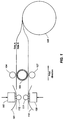
- a common method is to use two thermal print heads 102, 109, by first driving the rolled print medium 106 via drive roller (or capstan roller) 105 and pinch roller 104, in cooperation with a motor drive (not shown) on roll 106, to between platen roller 112 and one thermal print head 102 (print medium path of travel is shown in solid line), and printing on one side, Side A, of the print medium using dye donor 101.
- a length of print medium received from print medium roll 106 driven through the drive roller 105 and pinch roller 104 exposes Side B to come into contact with the drive roller's surface texture, compromising the Side B surface for subsequent printing.
- the Side B surface is compromised via the textured drive roller 105 perforating, forming depressions, pitting, or indenting the outermost layer, or more layers, of the Side B surface.
- the print media is then re-positioned by reversing drive roller 105 and pinch roller 104 in cooperation with the motor drive on roll 106, so that the lead edge of the paper is retracted toward the supply roll 106 and then diverted to the path represented by the dashed line.
- the rolled print medium 106 is driven via drive roller (or capstan roller) 105, pinch roller 107, in cooperation with the motor drive on roll 106, to between platen roller 111 and the second thermal print head 109.
- the non-printed surface, Side B, of the print medium is then printed using dye donor 110.
- EP-2357087 discloses a duplex printing method for printing on both sides of a roll sheet by a thermal transfer method.
- a preferred embodiment of the present patent application comprises a method of printing comprising receiving a two-sided medium in a printer, printing on a first side of the medium, smoothing a second side of the medium after printing the first side and, while the medium remains in the printer, printing on the second side of the medium.
- the smoothing is accomplished by heating the second side of the medium by compressing the medium against a heated surface which can be implemented as a heated roller.
- a plurality of rollers can be used wherein at least one of the plurality of rollers is heated and wherein the print medium is pressed against the heated roller.
- a heated roller can be implemented similarly with an electric current passing through the roller for generating heat.
- Another preferred embodiment of the present invention comprises a method of printing by receiving a duplex printing medium inside a printer, including using a textured roller pressed against a first side of the duplex printing medium for drawing the printing medium into the printer.
- a second side of the printing medium is printed including using a thermal print head. Smoothing the first side of the duplex printing medium, after the step of printing on the second side of the duplex printing medium, causes a size of indentations in the first side of the duplex printing medium to be reduced. After the depression reduction, the first side of the duplex printing medium is printed.
- Another preferred embodiment of the present invention comprises a method of handling a printing medium comprising pulling the printing medium through a nip formed between a pinch roller and a textured capstan roller, wherein the capstan roller compromises a capability of one side of the printing medium to receive donor dye applied by a thermal print head to the one side of the printing medium by forming a plurality of indentations thereon.
- the one side of the printing medium is smoothed after the step of pulling the printing medium by heating the one side of the printing medium. This is accomplished by pulling the printing medium through a nip formed by a pinch roller and a heated roller.
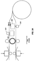
- FIG. 2 A preferred method and apparatus for printing is described in detail herein, and is illustrated in FIG. 2 wherein components common to FIG. 1 are operable as described above.
- the pressure roller 103a will press the print medium against heated roller 108 and the combination of heat and pressure will reduce a size of the depressed points of the Side B surface left by the drive roller 105.
- the printer is also operable in a reverse sequence as described herein wherein Side B is printed first and Side A depressions formed by drive roller 105 are reduced by compression between pressure roller 103b and heated roller 108.
- FIG. 2 shows pressure roller 103a forming a nip with heated roller 108, however, both pressure rollers 103a and 103b are moveable to and from a position against heated roller 108 to form a nip therewith as needed.
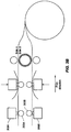
- the heating roller is similar to a fuser roller used in electrophotographic printers which uses an electric current passing through the roller for heating or, in an alternative preferred embodiment ( FIGs. 3A and 3B ), the heating devices comprise two additional thermal print heads 208 and platen rollers 203 whose sole purpose is to smooth the printing medium surface.
- the heating devices are operable to heal the printing medium according to the present invention if disposed as illustrated in FIG. 3A or as illustrated in FIG. 3B .
- the print media is retracted toward the supply roll, as before, and then diverted along the pathway represented by the dashed line.
- the capstan and pinch roller drive the print medium between the printhead and platen roller such that a length of the print medium extends beyond the printhead. This is because the print medium is pulled from left to right, as shown in the Figures, during the thermal printing step.
- the pressure roller 303b will press the print medium against heated roller 308b and the combination of heat and pressure will reduce a size of the depressed points of the Side B surface left by the drive roller.
- the printer is also operable in a reverse sequence wherein Side B is printed first and Side A depressions formed by the drive roller are reduced by compression between pressure roller 303a and heated roller 308a prior to printing Side A.
- a smooth drive roller is used with increased pressure against the pinch roller to compensate for lost traction due to lack of an aggressive texture on the drive roller.
- This increased pressure can also cause depressions or indentations, i.e. "tracks", in the duplex receiver resulting in across the page density variations.
- the embodiments of the invention disclosed herein also serve to correct for these variations.
- the textured drive roller typically comprises protrusions extending from its cylindrical surface at a distance of about 25 microns.
- This breadboard allows temperature and line speed to be changed at a constant pressure between the nip formed by the heated roller 108 and pressure roller 103a or 103b, which is an elastomer nip.
- the measured nip width using a pressure sensitive medium was 5 mm. This width is measured lengthwise along the print medium and is formed by the pressure of the heated roller against the compliant pressure roller with the print medium therebetween. Increased pressure increases the nip width as would a larger diameter heated roller, a larger diameter compliant pressure roller, or if either roller was made to be more compliant. Increased nip width increases an amount of heat transferred to the print medium.
- Typical pressure rollers are steel core with a thick silicone rubber layer, and a thin Teflon coating as an outer layer. The heated roller is similar in design to a fuser roller used in most electrophotographic printers.
- L* Delta L*
- ⁇ L* is an arbitrary relative measure of lightness and the changes in L* shown in the graph of Fig. 5 should be interpreted relative to the other measured magnitudes.
- the magnitudes are measured using a densitometer. It is observed that samples with heat treatment (150° C, 70 mm/s) shows lower ⁇ L*, i.e. there is less visible difference between untouched medium and a capstan compromised medium.
- Heat treatment shows promise in healing the capstan roller marks and minimizing ⁇ L*. Improvements in this procedure could include the ability to change pressure in the nip to enable a healing process, or to use a thermal head to heal the holes ( Fig. 3 ).
- Alternative heating methods include a heating zone located between the capstan roller and the supply roll. The heating zone could comprise a heated band which does not stick to DRL. The heating zone could also contain a non-contact heating source.
- the thermal dye receiving medium can be manufactured by various well known techniques and materials for duplex thermal receivers. A preferred method and materials are described in US Patent Application Publication 2011/0091667 A1 .
Description
- The present invention is directed to thermal printing, in particular, to heat treatment of a dye receiver layer surface exposed to a capstan roller to reduce print density differential.
- It is a well known practice within dye diffusion thermal transfer printers that, in order to controllably drive the paper and maintain traction for precise image registration between color passes, an aggressively textured drive roller, and a companion pinch roller that applies a load between the paper and drive roller, is commonly used. This type of drive system does not result in any image artifacts on the printed paper when printing only on one side, or simplex printing, because the aggressively textured drive roller is not contacting the printed side of the paper. This method does present a problem when printing a two-sided, or duplex print because the aggressively textured drive roller must contact both sides of the printed sheet. For two-sided or duplex printing, the paper surface that is in contact with the aggressively textured surface of the drive roller may become compromised by the aggressively textured surface. This compromised paper surface may not receive dye transfer as readily, resulting in a visible density difference between the area of the paper that saw contact with the drive roller's aggressive texture and the area that did not contact the aggressive texture.
- It is also common practice within the dye diffusion thermal transfer printer firmware to incorporate compensation algorithms that correct for across the page density variations, and/or down the page density variations. There may be limitations within the printer hardware or printer firmware such that compensation algorithms cannot completely compensate for printing artifacts generated by the drive roller. Due to these limitations, it becomes important to minimize the deviations in a print medium surface caused by the textured drive roller contacting the medium.
- With respect to
Fig. 1 , for two-sided or duplex dye diffusion thermal transfer printing, a common method is to use twothermal print heads print medium 106 via drive roller (or capstan roller) 105 andpinch roller 104, in cooperation with a motor drive (not shown) onroll 106, to betweenplaten roller 112 and one thermal print head 102 (print medium path of travel is shown in solid line), and printing on one side, Side A, of the print medium usingdye donor 101. A length of print medium received fromprint medium roll 106 driven through thedrive roller 105 andpinch roller 104 exposes Side B to come into contact with the drive roller's surface texture, compromising the Side B surface for subsequent printing. The Side B surface is compromised via thetextured drive roller 105 perforating, forming depressions, pitting, or indenting the outermost layer, or more layers, of the Side B surface. The print media is then re-positioned by reversingdrive roller 105 andpinch roller 104 in cooperation with the motor drive onroll 106, so that the lead edge of the paper is retracted toward thesupply roll 106 and then diverted to the path represented by the dashed line. The rolledprint medium 106 is driven via drive roller (or capstan roller) 105,pinch roller 107, in cooperation with the motor drive onroll 106, to betweenplaten roller 111 and the secondthermal print head 109. The non-printed surface, Side B, of the print medium is then printed usingdye donor 110. -
EP-2357087 discloses a duplex printing method for printing on both sides of a roll sheet by a thermal transfer method. - A preferred embodiment of the present patent application comprises a method of printing comprising receiving a two-sided medium in a printer, printing on a first side of the medium, smoothing a second side of the medium after printing the first side and, while the medium remains in the printer, printing on the second side of the medium. The smoothing is accomplished by heating the second side of the medium by compressing the medium against a heated surface which can be implemented as a heated roller. A plurality of rollers can be used wherein at least one of the plurality of rollers is heated and wherein the print medium is pressed against the heated roller. As in a fuser from an electrophotographic printer, a heated roller can be implemented similarly with an electric current passing through the roller for generating heat.
- Another preferred embodiment of the present invention comprises a method of printing by receiving a duplex printing medium inside a printer, including using a textured roller pressed against a first side of the duplex printing medium for drawing the printing medium into the printer. A second side of the printing medium is printed including using a thermal print head. Smoothing the first side of the duplex printing medium, after the step of printing on the second side of the duplex printing medium, causes a size of indentations in the first side of the duplex printing medium to be reduced. After the depression reduction, the first side of the duplex printing medium is printed.
- Another preferred embodiment of the present invention comprises a method of handling a printing medium comprising pulling the printing medium through a nip formed between a pinch roller and a textured capstan roller, wherein the capstan roller compromises a capability of one side of the printing medium to receive donor dye applied by a thermal print head to the one side of the printing medium by forming a plurality of indentations thereon. The one side of the printing medium is smoothed after the step of pulling the printing medium by heating the one side of the printing medium. This is accomplished by pulling the printing medium through a nip formed by a pinch roller and a heated roller.
- These, and other, aspects and objects of the present invention will be better appreciated and understood when considered in conjunction with the following description and the accompanying drawings. It should be understood, however, that the following description, while indicating preferred embodiments of the present invention and numerous specific details thereof, is given by way of illustration and not of limitation. For example, the summary descriptions above are not meant to describe individual separate embodiments whose elements are not interchangeable. In fact, many of the elements described as related to a particular embodiment can be used together with, and possibly interchanged with, elements of other described embodiments.
- The figures below are intended to be drawn neither to any precise scale with respect to relative size, angular relationship, or relative position nor to any combinational relationship with respect to interchangeability, substitution, or representation of an actual implementation.
- Preferred embodiments of the present invention will be more readily understood from the detailed description of exemplary embodiments presented below considered in conjunction with the attached drawings, of which:
-
FIG. 1 illustrates duplex printing in a thermal printer apparatus. -
FIG. 2 illustrates a print medium positioned in a modified thermal printer apparatus. -
FIG. 3 illustrates a print medium positioned in an alternative modified thermal printer apparatus. -
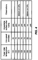
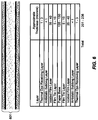
FIG. 4 illustrates experimental conditions used in a test fuser and the corresponding observations of a dye receiving layer's surface quality. -
FIG. 5 illustrates test results of dye receiving layer under heat treatment according to embodiments of the present invention. -
FIG. 6 illustrates a duplex receiver layer structure with thicknesses. - A preferred method and apparatus for printing is described in detail herein, and is illustrated in
FIG. 2 wherein components common toFIG. 1 are operable as described above. After completion of printing on print medium Side A as described above, as the print media is being retracted toward thesupply roll 106, the pressure roller 103a will press the print medium against heatedroller 108 and the combination of heat and pressure will reduce a size of the depressed points of the Side B surface left by thedrive roller 105. The printer is also operable in a reverse sequence as described herein wherein Side B is printed first and Side A depressions formed bydrive roller 105 are reduced by compression between pressure roller 103b and heatedroller 108.FIG. 2 shows pressure roller 103a forming a nip with heatedroller 108, however, both pressure rollers 103a and 103b are moveable to and from a position against heatedroller 108 to form a nip therewith as needed. The heating roller is similar to a fuser roller used in electrophotographic printers which uses an electric current passing through the roller for heating or, in an alternative preferred embodiment (FIGs. 3A and3B ), the heating devices comprise two additionalthermal print heads 208 andplaten rollers 203 whose sole purpose is to smooth the printing medium surface. The heating devices are operable to heal the printing medium according to the present invention if disposed as illustrated inFIG. 3A or as illustrated inFIG. 3B . - With reference to
FIG. 3B , after completion of printing on print medium Side A as described above, the print media is retracted toward the supply roll, as before, and then diverted along the pathway represented by the dashed line. The capstan and pinch roller drive the print medium between the printhead and platen roller such that a length of the print medium extends beyond the printhead. This is because the print medium is pulled from left to right, as shown in the Figures, during the thermal printing step. At this point, while the print medium is extended beyond the printhead and platen roller and is being pulled toward the printhead for printing, the pressure roller 303b will press the print medium against heated roller 308b and the combination of heat and pressure will reduce a size of the depressed points of the Side B surface left by the drive roller. The printer is also operable in a reverse sequence wherein Side B is printed first and Side A depressions formed by the drive roller are reduced by compression between pressure roller 303a and heated roller 308a prior to printing Side A. - It is known from experimentation that, during the printing operation described above, holes, depressions, perforations, or indentations are created by the capstan roller on the side opposite to the side being printed. These holes are crescent shaped indentations in the outer dye receiver layer (DRL). Depending on the type of media, these holes might penetrate the DRL resulting in perforations in the DRL. Because the DRL is a flexible layer, it may be indented or perforated by the drive roller. Whether the DRL is indented or perforated by the drive roller, the heating step improves the DRL surface for receiving the dye donor and results in improved print quality. It should be noted that some duplex thermal printer designs are envisioned without a textured drive roller. Rather, a smooth drive roller is used with increased pressure against the pinch roller to compensate for lost traction due to lack of an aggressive texture on the drive roller. This increased pressure can also cause depressions or indentations, i.e. "tracks", in the duplex receiver resulting in across the page density variations. The embodiments of the invention disclosed herein also serve to correct for these variations.
- With reference to
FIG. 6 , there is illustrated the thicknesses of various layers in theduplex receiver structure 601 contemplated by a preferred embodiment of the present invention. Other duplex receiver materials may be similarly improved with use of the embodiments of the present invention. The textured drive roller typically comprises protrusions extending from its cylindrical surface at a distance of about 25 microns. - When this compromised DRL surface is printed the print density at areas corresponding to the capstan roller is lower than the print density found in the rest of the print. It was hypothesized (and observed by microscopy) that the holes do not get filled up with dye as intended by a thermal printing step and hence the half tone effect results in visibly lower print density. A two sided thermal receiver (medium) comprising a voided biaxially oriented polypropylene laminate was run through once for testing purposes. The one time run through means that the receiver was pulled or driven through the capstan rollers one time without printing. Experiments evaluated the effect of heat treatment on the unprinted DRL surface exposed to the capstan roller. The heat treatment was applied using an electrophotographic fuser breadboard. This breadboard allows temperature and line speed to be changed at a constant pressure between the nip formed by the
heated roller 108 and pressure roller 103a or 103b, which is an elastomer nip. The measured nip width using a pressure sensitive medium was 5 mm. This width is measured lengthwise along the print medium and is formed by the pressure of the heated roller against the compliant pressure roller with the print medium therebetween. Increased pressure increases the nip width as would a larger diameter heated roller, a larger diameter compliant pressure roller, or if either roller was made to be more compliant. Increased nip width increases an amount of heat transferred to the print medium. Typical pressure rollers are steel core with a thick silicone rubber layer, and a thin Teflon coating as an outer layer. The heated roller is similar in design to a fuser roller used in most electrophotographic printers. - Ten feet of each variation was created to enable testing the heated capstan roller exposed DRL side in the printer. Observations were recorded as illustrated in
Fig. 4 . For a given temperature and line speed condition (e.g., 150 C, 70 mm/sec) the print medium (receiver) was run twice and thrice through the nip. We consider running the medium twice through a 5 mm nip as equivalent to exposing the medium to a 10 mm nip width (though in a discontinuous manner, because the receiver cools in between the heating steps) and running thrice as equivalent to exposure to a 15 mm of nip width (though in a discontinuous manner, as above).Fig. 5 highlights difference in Delta L* (ΔL*) between a capstan roller compromised area of the print medium and a capstan-untouched portion of the print medium. L* is an arbitrary relative measure of lightness and the changes in L* shown in the graph ofFig. 5 should be interpreted relative to the other measured magnitudes. The magnitudes are measured using a densitometer. It is observed that samples with heat treatment (150° C, 70 mm/s) shows lower ΔL*, i.e. there is less visible difference between untouched medium and a capstan compromised medium. - Heat treatment shows promise in healing the capstan roller marks and minimizing ΔL*. Improvements in this procedure could include the ability to change pressure in the nip to enable a healing process, or to use a thermal head to heal the holes (
Fig. 3 ). Alternative heating methods include a heating zone located between the capstan roller and the supply roll. The heating zone could comprise a heated band which does not stick to DRL. The heating zone could also contain a non-contact heating source. - The thermal dye receiving medium can be manufactured by various well known techniques and materials for duplex thermal receivers. A preferred method and materials are described in
US Patent Application Publication 2011/0091667 A1 . -
- 101
- Donor
- 102
- Thermal Print Head
- 103a
- Compliant Pressure Roller
- 103b
- Compliant Pressure Roller
- 104
- Pinch Roller
- 105
- Capstan Roller
- 106
- Paper (Medium) Roll
- 107
- Pinch Roller
- 108
- Heated Roller
- 109
- Thermal Print Head
- 110
- Donor
- 111
- Platen Roller
- 112
- Platen Roller
- 203
- Platen Rollers
- 208
- Thermal Heads
Claims (19)
- A method of printing comprising the following steps in order:using a drive roller to position a two-sided medium in a printer;printing on a first side of the medium using the printer;smoothing a second side of the medium; andprinting on the second side of the medium using the printer.
- The method of claim 1 wherein the step of smoothing comprises heating the second side of the medium while the medium remains in the printer.
- The method of claim 2 wherein the step of heating comprises compressing the medium against a heated surface.
- The method of claim 3 wherein the step of compressing comprises using a heated roller.
- The method of claim 4 wherein the step of compressing comprises compressing the medium between at least two rollers, wherein at least one of the rollers is the heated surface.
- The method of claim 3 wherein heating is caused by passing an electric current through the heated surface.
- The method of claim 6 further comprising passing the electric current through the heated surface while the medium is being compressed against the heated surface.
- Method of printing comprising:receiving a duplex printing medium inside a printer, including using a textured roller pressed against a first side of the duplex printing medium for drawing the printing medium into the printer;printing on a second side of the duplex printing medium including using a thermal print head;smoothing the first side of the duplex printing medium, wherein a size of indentations in the first side of the duplex printing medium caused by the textured roller is reduced; andprinting on the first side of the duplex printing medium after the step of smoothing.
- Method of claim 8 wherein the step of smoothing comprises heating the first side of the duplex printing medium after the step of printing on the second side of the duplex printing medium.
- Method of claim 9 wherein the step of heating comprises compressing the duplex printing medium against a heated surface.
- Method of claim 10 wherein the step of compressing comprises using a heated roller.
- Method of claim 11 wherein the step of using a heated roller comprises using a plurality of rollers wherein at least one of the plurality of rollers is heated.
- Method of claim 10 further comprising heating the heated surface by passing an electric current therethrough.
- Method of claim 13 further comprising passing the electric current through the heated surface while the duplex printing medium is being compressed against the heated surface.
- A method of handling a printing medium comprising:pulling the printing medium through a nip formed between a pinch roller and a textured capstan roller, wherein the capstan roller compromises a capability of one side of the printing medium to receive donor dye applied by a thermal print head to the one side of the printing medium by forming a plurality of indentations thereon; andsmoothing the one side of the printing medium after the step of pulling the printing medium.
- Method of claim 15 wherein the step of smoothing comprises heating the one side of the printing medium.
- Method of claim 16 wherein the step of heating comprises pulling the printing medium through a nip formed by a pinch roller and a heated roller.
- Method of claim 17 wherein the heated roller is heated by passing an electric current therethrough.
- Method of claim 18 further comprising passing the electric current through the heated roller during the step of pulling the printing medium through the nip formed by the pinch roller and the heated roller.
Applications Claiming Priority (2)
| Application Number | Priority Date | Filing Date | Title |
|---|---|---|---|
| US13/422,045 US8743163B2 (en) | 2012-03-16 | 2012-03-16 | Printing method for reducing printer artifacts |
| PCT/US2013/031135 WO2013138543A1 (en) | 2012-03-16 | 2013-03-14 | Printing method for reducing printer artifacts |
Publications (2)
| Publication Number | Publication Date |
|---|---|
| EP2825390A1 EP2825390A1 (en) | 2015-01-21 |
| EP2825390B1 true EP2825390B1 (en) | 2016-03-09 |
Family
ID=48048198
Family Applications (1)
| Application Number | Title | Priority Date | Filing Date |
|---|---|---|---|
| EP13714395.4A Active EP2825390B1 (en) | 2012-03-16 | 2013-03-14 | Printing method for reducing printer artifacts |
Country Status (7)
| Country | Link |
|---|---|
| US (2) | US8743163B2 (en) |
| EP (1) | EP2825390B1 (en) |
| JP (1) | JP2015511898A (en) |
| KR (1) | KR20140136038A (en) |
| CN (2) | CN107053865B (en) |
| IN (1) | IN2014DN07546A (en) |
| WO (1) | WO2013138543A1 (en) |
Families Citing this family (5)
| Publication number | Priority date | Publication date | Assignee | Title |
|---|---|---|---|---|
| US8743163B2 (en) * | 2012-03-16 | 2014-06-03 | Kodak Alaris Inc. | Printing method for reducing printer artifacts |
| US8749604B2 (en) * | 2012-03-16 | 2014-06-10 | Kodak Alaris Inc. | Printing system for reducing printer artifacts |
| US8599229B1 (en) * | 2012-06-26 | 2013-12-03 | Kodak Alaris Inc. | Roll-fed duplex thermal printing system |
| JP5996469B2 (en) * | 2013-03-28 | 2016-09-21 | シチズンホールディングス株式会社 | Printer |
| EP3356144B1 (en) * | 2015-10-02 | 2020-12-23 | Assa Abloy Ab | Card substrate laminating device and method |
Family Cites Families (19)
| Publication number | Priority date | Publication date | Assignee | Title |
|---|---|---|---|---|
| JPS58140275A (en) * | 1982-02-17 | 1983-08-19 | Toshiba Corp | Printer |
| GB2117707B (en) * | 1982-02-17 | 1985-07-10 | Tokyo Shibaura Electric Co | Thermal transfer type printing apparatus |
| JPS59155081A (en) * | 1983-02-23 | 1984-09-04 | Hitachi Ltd | Thermal recorder |
| JPS61173957A (en) * | 1985-01-29 | 1986-08-05 | Citizen Watch Co Ltd | Thermal transfer printer |
| JPS61206683A (en) * | 1985-03-12 | 1986-09-12 | Yokogawa Electric Corp | Thermal transfer printer |
| US5284816A (en) * | 1992-11-19 | 1994-02-08 | Eastman Kodak Company | Two-sided thermal printing system |
| JP2000296607A (en) * | 1999-04-16 | 2000-10-24 | Mutoh Ind Ltd | Ink jet printer |
| US6361228B1 (en) * | 1999-05-27 | 2002-03-26 | Printronix, Inc. | Thermal printer with improved ribbon transport |
| US6784906B2 (en) * | 2001-12-18 | 2004-08-31 | Ncr Corporation | Direct thermal printer |
| AU2003235291A1 (en) * | 2003-04-18 | 2004-11-19 | Mimaki Engineering Co., Ltd. | Ink jet printer |
| CN1880097A (en) * | 2005-06-15 | 2006-12-20 | 金宝电子工业股份有限公司 | Paper feeding module for double face printing, and double face printing method |
| US20070120942A1 (en) * | 2005-11-30 | 2007-05-31 | Ncr Corporation | Dual-sided two color thermal printing |
| CN2925872Y (en) * | 2006-07-25 | 2007-07-25 | 李新忠 | Satellite printer with double printing |
| US8848010B2 (en) * | 2007-07-12 | 2014-09-30 | Ncr Corporation | Selective direct thermal and thermal transfer printing |
| US8773483B2 (en) * | 2008-11-14 | 2014-07-08 | Dai Nippon Printing Co., Ltd. | Duplex printing method, bookbinding method, printer for use in duplex printing method |
| JP2011046156A (en) * | 2009-08-28 | 2011-03-10 | Sinfonia Technology Co Ltd | Thermal printer and printing method |
| JP5043984B2 (en) * | 2010-05-10 | 2012-10-10 | キヤノン株式会社 | Printing apparatus and installation method of printing apparatus |
| US8749604B2 (en) * | 2012-03-16 | 2014-06-10 | Kodak Alaris Inc. | Printing system for reducing printer artifacts |
| US8743163B2 (en) * | 2012-03-16 | 2014-06-03 | Kodak Alaris Inc. | Printing method for reducing printer artifacts |
-
2012
- 2012-03-16 US US13/422,045 patent/US8743163B2/en active Active
-
2013
- 2013-03-14 CN CN201710030812.4A patent/CN107053865B/en not_active Expired - Fee Related
- 2013-03-14 WO PCT/US2013/031135 patent/WO2013138543A1/en active Application Filing
- 2013-03-14 CN CN201380014723.0A patent/CN104169096B/en not_active Expired - Fee Related
- 2013-03-14 EP EP13714395.4A patent/EP2825390B1/en active Active
- 2013-03-14 JP JP2015500587A patent/JP2015511898A/en active Pending
- 2013-03-14 KR KR20147028713A patent/KR20140136038A/en not_active Application Discontinuation
- 2013-03-14 IN IN7546DEN2014 patent/IN2014DN07546A/en unknown
-
2014
- 2014-04-22 US US14/258,697 patent/US9056487B2/en active Active
Also Published As
| Publication number | Publication date |
|---|---|
| CN107053865A (en) | 2017-08-18 |
| WO2013138543A1 (en) | 2013-09-19 |
| US8743163B2 (en) | 2014-06-03 |
| IN2014DN07546A (en) | 2015-04-24 |
| CN107053865B (en) | 2018-12-21 |
| CN104169096B (en) | 2017-02-22 |
| US20130242027A1 (en) | 2013-09-19 |
| US20140267532A1 (en) | 2014-09-18 |
| KR20140136038A (en) | 2014-11-27 |
| EP2825390A1 (en) | 2015-01-21 |
| JP2015511898A (en) | 2015-04-23 |
| US9056487B2 (en) | 2015-06-16 |
| CN104169096A (en) | 2014-11-26 |
Similar Documents
| Publication | Publication Date | Title |
|---|---|---|
| US20140267536A1 (en) | Printing system for reducing printer artifacts | |
| US9056487B2 (en) | Printing method for reducing printer artifacts | |
| KR20170044083A (en) | Intermediate transfer film having substantially transparent alignment marks | |
| JP2018126925A (en) | Printer and printer control program | |
| JP2012171298A (en) | Surface treatment apparatus | |
| JP4333705B2 (en) | Thermal printer and image forming method | |
| US20110091256A1 (en) | Image forming apparatus and method of controlling the same | |
| JP3741847B2 (en) | Thermal coloring printing method, thermal head and printer | |
| EP3580060B1 (en) | Transfer film having a roller cleaning section | |
| US20030007061A1 (en) | Image-forming apparatus | |
| EP1947529A3 (en) | Fusing Device and Image Forming Apparatus using the Same | |
| JP2006007662A (en) | Thermal transfer printer | |
| US9764572B2 (en) | Printer | |
| ATE519597T1 (en) | PRINTER | |
| JP5581695B2 (en) | Thermal transfer image forming apparatus and image forming method | |
| JP2005162470A (en) | Roll paper feeder and recording apparatus | |
| JPH08192547A (en) | Printing paper carrying device for printer | |
| JP2005272078A (en) | Printer | |
| JP2011081237A (en) | Fixing device | |
| JP2005145581A (en) | Image forming device | |
| JP2004314636A (en) | Dye transfer printer | |
| JP3158891U (en) | Direct sublimation printing device | |
| JP2011093252A (en) | Paper carrying mechanism and thermal transfer printer | |
| JP2004223738A (en) | Overcoat layer printing device | |
| JP2004136562A (en) | Thermal transfer printer |
Legal Events
| Date | Code | Title | Description |
|---|---|---|---|
| PUAI | Public reference made under article 153(3) epc to a published international application that has entered the european phase |
Free format text: ORIGINAL CODE: 0009012 |
|
| 17P | Request for examination filed |
Effective date: 20141013 |
|
| AK | Designated contracting states |
Kind code of ref document: A1 Designated state(s): AL AT BE BG CH CY CZ DE DK EE ES FI FR GB GR HR HU IE IS IT LI LT LU LV MC MK MT NL NO PL PT RO RS SE SI SK SM TR |
|
| AX | Request for extension of the european patent |
Extension state: BA ME |
|
| DAX | Request for extension of the european patent (deleted) | ||
| GRAP | Despatch of communication of intention to grant a patent |
Free format text: ORIGINAL CODE: EPIDOSNIGR1 |
|
| INTG | Intention to grant announced |
Effective date: 20150819 |
|
| GRAS | Grant fee paid |
Free format text: ORIGINAL CODE: EPIDOSNIGR3 |
|
| GRAA | (expected) grant |
Free format text: ORIGINAL CODE: 0009210 |
|
| AK | Designated contracting states |
Kind code of ref document: B1 Designated state(s): AL AT BE BG CH CY CZ DE DK EE ES FI FR GB GR HR HU IE IS IT LI LT LU LV MC MK MT NL NO PL PT RO RS SE SI SK SM TR |
|
| REG | Reference to a national code |
Ref country code: GB Ref legal event code: FG4D |
|
| REG | Reference to a national code |
Ref country code: AT Ref legal event code: REF Ref document number: 779194 Country of ref document: AT Kind code of ref document: T Effective date: 20160315 Ref country code: CH Ref legal event code: EP |
|
| REG | Reference to a national code |
Ref country code: FR Ref legal event code: PLFP Year of fee payment: 4 |
|
| REG | Reference to a national code |
Ref country code: IE Ref legal event code: FG4D |
|
| REG | Reference to a national code |
Ref country code: DE Ref legal event code: R096 Ref document number: 602013005397 Country of ref document: DE |
|
| REG | Reference to a national code |
Ref country code: NL Ref legal event code: FP |
|
| REG | Reference to a national code |
Ref country code: LT Ref legal event code: MG4D |
|
| PG25 | Lapsed in a contracting state [announced via postgrant information from national office to epo] |
Ref country code: ES Free format text: LAPSE BECAUSE OF FAILURE TO SUBMIT A TRANSLATION OF THE DESCRIPTION OR TO PAY THE FEE WITHIN THE PRESCRIBED TIME-LIMIT Effective date: 20160309 Ref country code: HR Free format text: LAPSE BECAUSE OF FAILURE TO SUBMIT A TRANSLATION OF THE DESCRIPTION OR TO PAY THE FEE WITHIN THE PRESCRIBED TIME-LIMIT Effective date: 20160309 Ref country code: FI Free format text: LAPSE BECAUSE OF FAILURE TO SUBMIT A TRANSLATION OF THE DESCRIPTION OR TO PAY THE FEE WITHIN THE PRESCRIBED TIME-LIMIT Effective date: 20160309 Ref country code: GR Free format text: LAPSE BECAUSE OF FAILURE TO SUBMIT A TRANSLATION OF THE DESCRIPTION OR TO PAY THE FEE WITHIN THE PRESCRIBED TIME-LIMIT Effective date: 20160610 Ref country code: NO Free format text: LAPSE BECAUSE OF FAILURE TO SUBMIT A TRANSLATION OF THE DESCRIPTION OR TO PAY THE FEE WITHIN THE PRESCRIBED TIME-LIMIT Effective date: 20160609 |
|
| REG | Reference to a national code |
Ref country code: AT Ref legal event code: MK05 Ref document number: 779194 Country of ref document: AT Kind code of ref document: T Effective date: 20160309 |
|
| PG25 | Lapsed in a contracting state [announced via postgrant information from national office to epo] |
Ref country code: BE Free format text: LAPSE BECAUSE OF NON-PAYMENT OF DUE FEES Effective date: 20160331 Ref country code: RS Free format text: LAPSE BECAUSE OF FAILURE TO SUBMIT A TRANSLATION OF THE DESCRIPTION OR TO PAY THE FEE WITHIN THE PRESCRIBED TIME-LIMIT Effective date: 20160309 Ref country code: LT Free format text: LAPSE BECAUSE OF FAILURE TO SUBMIT A TRANSLATION OF THE DESCRIPTION OR TO PAY THE FEE WITHIN THE PRESCRIBED TIME-LIMIT Effective date: 20160309 Ref country code: LV Free format text: LAPSE BECAUSE OF FAILURE TO SUBMIT A TRANSLATION OF THE DESCRIPTION OR TO PAY THE FEE WITHIN THE PRESCRIBED TIME-LIMIT Effective date: 20160309 Ref country code: PL Free format text: LAPSE BECAUSE OF FAILURE TO SUBMIT A TRANSLATION OF THE DESCRIPTION OR TO PAY THE FEE WITHIN THE PRESCRIBED TIME-LIMIT Effective date: 20160309 Ref country code: SE Free format text: LAPSE BECAUSE OF FAILURE TO SUBMIT A TRANSLATION OF THE DESCRIPTION OR TO PAY THE FEE WITHIN THE PRESCRIBED TIME-LIMIT Effective date: 20160309 |
|
| PG25 | Lapsed in a contracting state [announced via postgrant information from national office to epo] |
Ref country code: IS Free format text: LAPSE BECAUSE OF FAILURE TO SUBMIT A TRANSLATION OF THE DESCRIPTION OR TO PAY THE FEE WITHIN THE PRESCRIBED TIME-LIMIT Effective date: 20160709 Ref country code: EE Free format text: LAPSE BECAUSE OF FAILURE TO SUBMIT A TRANSLATION OF THE DESCRIPTION OR TO PAY THE FEE WITHIN THE PRESCRIBED TIME-LIMIT Effective date: 20160309 |
|
| REG | Reference to a national code |
Ref country code: CH Ref legal event code: PL |
|
| PG25 | Lapsed in a contracting state [announced via postgrant information from national office to epo] |
Ref country code: SK Free format text: LAPSE BECAUSE OF FAILURE TO SUBMIT A TRANSLATION OF THE DESCRIPTION OR TO PAY THE FEE WITHIN THE PRESCRIBED TIME-LIMIT Effective date: 20160309 Ref country code: CZ Free format text: LAPSE BECAUSE OF FAILURE TO SUBMIT A TRANSLATION OF THE DESCRIPTION OR TO PAY THE FEE WITHIN THE PRESCRIBED TIME-LIMIT Effective date: 20160309 Ref country code: AT Free format text: LAPSE BECAUSE OF FAILURE TO SUBMIT A TRANSLATION OF THE DESCRIPTION OR TO PAY THE FEE WITHIN THE PRESCRIBED TIME-LIMIT Effective date: 20160309 Ref country code: RO Free format text: LAPSE BECAUSE OF FAILURE TO SUBMIT A TRANSLATION OF THE DESCRIPTION OR TO PAY THE FEE WITHIN THE PRESCRIBED TIME-LIMIT Effective date: 20160309 Ref country code: PT Free format text: LAPSE BECAUSE OF FAILURE TO SUBMIT A TRANSLATION OF THE DESCRIPTION OR TO PAY THE FEE WITHIN THE PRESCRIBED TIME-LIMIT Effective date: 20160711 Ref country code: SM Free format text: LAPSE BECAUSE OF FAILURE TO SUBMIT A TRANSLATION OF THE DESCRIPTION OR TO PAY THE FEE WITHIN THE PRESCRIBED TIME-LIMIT Effective date: 20160309 |
|
| REG | Reference to a national code |
Ref country code: DE Ref legal event code: R097 Ref document number: 602013005397 Country of ref document: DE |
|
| REG | Reference to a national code |
Ref country code: IE Ref legal event code: MM4A |
|
| PG25 | Lapsed in a contracting state [announced via postgrant information from national office to epo] |
Ref country code: BE Free format text: LAPSE BECAUSE OF FAILURE TO SUBMIT A TRANSLATION OF THE DESCRIPTION OR TO PAY THE FEE WITHIN THE PRESCRIBED TIME-LIMIT Effective date: 20160309 Ref country code: IT Free format text: LAPSE BECAUSE OF FAILURE TO SUBMIT A TRANSLATION OF THE DESCRIPTION OR TO PAY THE FEE WITHIN THE PRESCRIBED TIME-LIMIT Effective date: 20160309 |
|
| PLBE | No opposition filed within time limit |
Free format text: ORIGINAL CODE: 0009261 |
|
| STAA | Information on the status of an ep patent application or granted ep patent |
Free format text: STATUS: NO OPPOSITION FILED WITHIN TIME LIMIT |
|
| PG25 | Lapsed in a contracting state [announced via postgrant information from national office to epo] |
Ref country code: IE Free format text: LAPSE BECAUSE OF NON-PAYMENT OF DUE FEES Effective date: 20160314 Ref country code: CH Free format text: LAPSE BECAUSE OF NON-PAYMENT OF DUE FEES Effective date: 20160331 Ref country code: LI Free format text: LAPSE BECAUSE OF NON-PAYMENT OF DUE FEES Effective date: 20160331 Ref country code: DK Free format text: LAPSE BECAUSE OF FAILURE TO SUBMIT A TRANSLATION OF THE DESCRIPTION OR TO PAY THE FEE WITHIN THE PRESCRIBED TIME-LIMIT Effective date: 20160309 |
|
| 26N | No opposition filed |
Effective date: 20161212 |
|
| REG | Reference to a national code |
Ref country code: FR Ref legal event code: PLFP Year of fee payment: 5 |
|
| PG25 | Lapsed in a contracting state [announced via postgrant information from national office to epo] |
Ref country code: BG Free format text: LAPSE BECAUSE OF FAILURE TO SUBMIT A TRANSLATION OF THE DESCRIPTION OR TO PAY THE FEE WITHIN THE PRESCRIBED TIME-LIMIT Effective date: 20160609 |
|
| PG25 | Lapsed in a contracting state [announced via postgrant information from national office to epo] |
Ref country code: SI Free format text: LAPSE BECAUSE OF FAILURE TO SUBMIT A TRANSLATION OF THE DESCRIPTION OR TO PAY THE FEE WITHIN THE PRESCRIBED TIME-LIMIT Effective date: 20160309 |
|
| PG25 | Lapsed in a contracting state [announced via postgrant information from national office to epo] |
Ref country code: MT Free format text: LAPSE BECAUSE OF FAILURE TO SUBMIT A TRANSLATION OF THE DESCRIPTION OR TO PAY THE FEE WITHIN THE PRESCRIBED TIME-LIMIT Effective date: 20160309 |
|
| REG | Reference to a national code |
Ref country code: FR Ref legal event code: PLFP Year of fee payment: 6 |
|
| PG25 | Lapsed in a contracting state [announced via postgrant information from national office to epo] |
Ref country code: HU Free format text: LAPSE BECAUSE OF FAILURE TO SUBMIT A TRANSLATION OF THE DESCRIPTION OR TO PAY THE FEE WITHIN THE PRESCRIBED TIME-LIMIT; INVALID AB INITIO Effective date: 20130314 |
|
| PG25 | Lapsed in a contracting state [announced via postgrant information from national office to epo] |
Ref country code: MT Free format text: LAPSE BECAUSE OF FAILURE TO SUBMIT A TRANSLATION OF THE DESCRIPTION OR TO PAY THE FEE WITHIN THE PRESCRIBED TIME-LIMIT Effective date: 20160331 Ref country code: LU Free format text: LAPSE BECAUSE OF NON-PAYMENT OF DUE FEES Effective date: 20160314 Ref country code: MK Free format text: LAPSE BECAUSE OF FAILURE TO SUBMIT A TRANSLATION OF THE DESCRIPTION OR TO PAY THE FEE WITHIN THE PRESCRIBED TIME-LIMIT Effective date: 20160309 Ref country code: MC Free format text: LAPSE BECAUSE OF FAILURE TO SUBMIT A TRANSLATION OF THE DESCRIPTION OR TO PAY THE FEE WITHIN THE PRESCRIBED TIME-LIMIT Effective date: 20160309 Ref country code: CY Free format text: LAPSE BECAUSE OF FAILURE TO SUBMIT A TRANSLATION OF THE DESCRIPTION OR TO PAY THE FEE WITHIN THE PRESCRIBED TIME-LIMIT Effective date: 20160309 |
|
| PG25 | Lapsed in a contracting state [announced via postgrant information from national office to epo] |
Ref country code: TR Free format text: LAPSE BECAUSE OF FAILURE TO SUBMIT A TRANSLATION OF THE DESCRIPTION OR TO PAY THE FEE WITHIN THE PRESCRIBED TIME-LIMIT Effective date: 20160309 Ref country code: AL Free format text: LAPSE BECAUSE OF FAILURE TO SUBMIT A TRANSLATION OF THE DESCRIPTION OR TO PAY THE FEE WITHIN THE PRESCRIBED TIME-LIMIT Effective date: 20160309 |
|
| PGFP | Annual fee paid to national office [announced via postgrant information from national office to epo] |
Ref country code: FR Payment date: 20200219 Year of fee payment: 8 |
|
| PG25 | Lapsed in a contracting state [announced via postgrant information from national office to epo] |
Ref country code: FR Free format text: LAPSE BECAUSE OF NON-PAYMENT OF DUE FEES Effective date: 20210331 |
|
| PGFP | Annual fee paid to national office [announced via postgrant information from national office to epo] |
Ref country code: GB Payment date: 20230208 Year of fee payment: 11 Ref country code: DE Payment date: 20230210 Year of fee payment: 11 |
|
| PGFP | Annual fee paid to national office [announced via postgrant information from national office to epo] |
Ref country code: NL Payment date: 20231220 Year of fee payment: 12 |