KR20140136038A - Printing method for reducing printer artifacts - Google Patents
Printing method for reducing printer artifacts Download PDFInfo
- Publication number
- KR20140136038A KR20140136038A KR20147028713A KR20147028713A KR20140136038A KR 20140136038 A KR20140136038 A KR 20140136038A KR 20147028713 A KR20147028713 A KR 20147028713A KR 20147028713 A KR20147028713 A KR 20147028713A KR 20140136038 A KR20140136038 A KR 20140136038A
- Authority
- KR
- South Korea
- Prior art keywords
- printing
- medium
- roller
- heated
- printing medium
- Prior art date
Links
Images
Classifications
-
- B—PERFORMING OPERATIONS; TRANSPORTING
- B41—PRINTING; LINING MACHINES; TYPEWRITERS; STAMPS
- B41J—TYPEWRITERS; SELECTIVE PRINTING MECHANISMS, i.e. MECHANISMS PRINTING OTHERWISE THAN FROM A FORME; CORRECTION OF TYPOGRAPHICAL ERRORS
- B41J2/00—Typewriters or selective printing mechanisms characterised by the printing or marking process for which they are designed
- B41J2/315—Typewriters or selective printing mechanisms characterised by the printing or marking process for which they are designed characterised by selective application of heat to a heat sensitive printing or impression-transfer material
-
- B—PERFORMING OPERATIONS; TRANSPORTING
- B41—PRINTING; LINING MACHINES; TYPEWRITERS; STAMPS
- B41J—TYPEWRITERS; SELECTIVE PRINTING MECHANISMS, i.e. MECHANISMS PRINTING OTHERWISE THAN FROM A FORME; CORRECTION OF TYPOGRAPHICAL ERRORS
- B41J11/00—Devices or arrangements of selective printing mechanisms, e.g. ink-jet printers or thermal printers, for supporting or handling copy material in sheet or web form
- B41J11/0005—Curl smoothing, i.e. smoothing down corrugated printing material, e.g. by pressing means acting on wrinkled printing material
-
- B—PERFORMING OPERATIONS; TRANSPORTING
- B41—PRINTING; LINING MACHINES; TYPEWRITERS; STAMPS
- B41J—TYPEWRITERS; SELECTIVE PRINTING MECHANISMS, i.e. MECHANISMS PRINTING OTHERWISE THAN FROM A FORME; CORRECTION OF TYPOGRAPHICAL ERRORS
- B41J3/00—Typewriters or selective printing or marking mechanisms characterised by the purpose for which they are constructed
- B41J3/60—Typewriters or selective printing or marking mechanisms characterised by the purpose for which they are constructed for printing on both faces of the printing material
-
- B—PERFORMING OPERATIONS; TRANSPORTING
- B41—PRINTING; LINING MACHINES; TYPEWRITERS; STAMPS
- B41M—PRINTING, DUPLICATING, MARKING, OR COPYING PROCESSES; COLOUR PRINTING
- B41M3/00—Printing processes to produce particular kinds of printed work, e.g. patterns
- B41M3/008—Sequential or multiple printing, e.g. on previously printed background; Mirror printing; Recto-verso printing; using a combination of different printing techniques; Printing of patterns visible in reflection and by transparency; by superposing printed artifacts
-
- B—PERFORMING OPERATIONS; TRANSPORTING
- B41—PRINTING; LINING MACHINES; TYPEWRITERS; STAMPS
- B41M—PRINTING, DUPLICATING, MARKING, OR COPYING PROCESSES; COLOUR PRINTING
- B41M5/00—Duplicating or marking methods; Sheet materials for use therein
- B41M5/0011—Pre-treatment or treatment during printing of the recording material, e.g. heating, irradiating
-
- B—PERFORMING OPERATIONS; TRANSPORTING
- B41—PRINTING; LINING MACHINES; TYPEWRITERS; STAMPS
- B41M—PRINTING, DUPLICATING, MARKING, OR COPYING PROCESSES; COLOUR PRINTING
- B41M5/00—Duplicating or marking methods; Sheet materials for use therein
- B41M5/26—Thermography ; Marking by high energetic means, e.g. laser otherwise than by burning, and characterised by the material used
- B41M5/382—Contact thermal transfer or sublimation processes
- B41M5/38207—Contact thermal transfer or sublimation processes characterised by aspects not provided for in groups B41M5/385 - B41M5/395
- B41M5/38221—Apparatus features
-
- B—PERFORMING OPERATIONS; TRANSPORTING
- B41—PRINTING; LINING MACHINES; TYPEWRITERS; STAMPS
- B41M—PRINTING, DUPLICATING, MARKING, OR COPYING PROCESSES; COLOUR PRINTING
- B41M7/00—After-treatment of prints, e.g. heating, irradiating, setting of the ink, protection of the printed stock
Abstract
프린팅을 위한 프린트헤드 및 롤러들을 포함하는 프린팅 방법. 프린트 작업의 페이지는 프린트되어 프린트 매체의 프린트되지 않은 면에 함몰부들을 유발한다. 상기 프린트 매체는 프린트되지 않은 면을 프린팅하기 전 함몰부들을 감소시키기 위해 가열된다.A printing method comprising a printhead and rollers for printing. The page of the print job is printed to cause depressions on the unprinted side of the print medium. The print medium is heated to reduce depressions before printing the unprinted side.

Description
본 발명은 서멀 프린팅(thermal printing), 특히, 프린트 밀도 차이를 감소시키기 위해 캡스턴 롤러(capstan roller)에 노출된 염료 수용기 층 표면(dye receiver layer surface)의 열 처리에 관한 것이다.The present invention relates to thermal printing, and more particularly to thermal treatment of a dye receiver layer surface exposed to a capstan roller to reduce print density differences.
종이를 제어 가능하게 구동하고 컬러 통로들 사이에서 정확한 이미지 등록을 위한 견인력을 유지하기 위해, 거칠게 질감이 나는(aggressively textured) 드라이브 롤러, 및 종이와 드라이브 롤러 사이에 하중을 부과하는 컴패니언 핀치 롤러(companion pinch roller),가 일반적으로 이용되는 것이 염료 확산 서멀 전사 프린터(dye diffusion thermal transfer printer)들 내에서 잘 알려진 방법이다. 이러한 유형의 드라이브 시스템은 오직 일 면 상에 프린팅하거나, 단일 프린팅(simplex printing)시 상기 프린트된 종이 상에 어떠한 이미지 아티팩트들도 생기지 않는데, 거칠게 질감이 나는 드라이브 롤러가 종이의 프린트되는 면에 접촉되지 않기 때문이다. 이러한 방법은 양면을 프린팅하거나, 이중 프린트(duplex print)시 문제를 나타내는데, 거칠게 질감이 나는 드라이브 롤러가 프린트된 시트의 양쪽 면들에 접촉해야되기 때문이다. 양면 또는 이중 프린팅에 대해, 드라이브 롤러의 거칠게 질감이 나는 표면과 접촉하는 종이 표면은 거칠게 질감이 나는 표면에 의해 손상될 수도 있다. 이러한 손상된 종이 표면은 염료 전사를 쉽게 수용할 수 없어서, 드라이브 롤러의 거친 질감과 접촉한 것으로 보이는 종이의 영역과 상기 거친 질감과 접촉하지 않은 영역 사이에 가시적인 밀도 차이의 결과가 된다.In order to controllably drive the paper and maintain traction for accurate image registration between color passageways, a drive roller that is aggressively textured, and a companion pinch roller (companion) that applies a load between the paper and the drive roller pinch rollers are commonly used in dye diffusion thermal transfer printers. This type of drive system prints on only one side or does not produce any image artifacts on the printed paper upon simplex printing because the roughly textured drive roller does not come into contact with the printed side of the paper It is not. This method is problematic when printing on both sides or duplex printing because the roughly textured drive roller must contact both sides of the printed sheet. For double-sided or double-printing, the paper surface in contact with the roughly textured surface of the drive roller may be damaged by the roughly textured surface. This damaged paper surface can not readily accept dye transfer, resulting in a visible density difference between the area of the paper that appears to be in contact with the rough texture of the drive roller and the area that is not in contact with the rough texture.
또한 페이지 밀도 변화들을 가로질러 정정하며, 그리고/또는 페이지 밀도 변화들을 낮추는 보상 알고리즘들을 포함하는 것이 염료 확산 서멀 전사 프린터 펌웨어 내에서 일반적인 방법이다. 보상 알고리즘들이 드라이브 롤러에 의해 발생된 프린팅 아티팩트들을 완전히 보상할 수 없도록 프린터 하드웨어 또는 프린터 펌웨어 내에 제한들이 있을 수 있다. 이러한 제한들 때문에, 매체(medium)와 접촉하는 질감이 나는 드라이브 롤러에 의해 유발된 프린트 매체 표면의 편차들을 최소화하는 것이 중요해진다.It is also common practice within the dye diffusion thermal transfer printer firmware to include compensation algorithms that correct across page density variations and / or lower page density variations. There may be limitations in the printer hardware or printer firmware such that the compensation algorithms can not completely compensate for the printing artifacts caused by the drive roller. Because of these limitations, it is important to minimize deviations in the print media surface caused by the textured drive roller in contact with the medium.
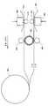
도 1과 관련하여, 양면 또는 이중 염료 확산 서멀 전사 프린팅을 위해, 통상의 방법은 두 개의 서멀 프린트 헤드들(thermal print heads)(102,109)을 이용하는 것이며, 롤(106) 상에 모터 드라이브(도시되지 않음)와 함께, 드라이브 롤러(또는 캡스턴 롤러)(105) 및 핀치 롤러(104)를 통해 말린(rolled) 프린트 매체(106)를 플래턴 롤러(platen roller)(112)와 하나의 서멀 프린트 헤드(102) 사이에서 먼저 구동하고(프린트 매체의 이동 경로는 실선으로 도시됨), 염료 도너(101)를 이용하여 프린트 매체의 일 면(면 A)에 프린팅한다. 상기 드라이브 롤러(105) 및 핀치 롤러(104)를 통해 구동된 프린트 매체 롤(106)로부터 수용된 프린트 매체의 한 길이는 드라이브 롤러의 표면 질감에 접촉되는 상태가 되도록 면 B를 노출시켜서, 다음 프린팅을 위한 면 B 표면을 손상시킨다. 상기 면 B 표면은 상기 질감이 나는 드라이브 롤러(105)를 통해 손상되어서, 면 B 표면의 최외곽 층, 또는 더 많은 층들에 구멍이 뚫리게 하고, 함몰부들을 형성하고, 흠집을 내고, 또는 옴폭 패게 한다. 그 다음에 상기 프린트 매체는 롤(106) 상에 모터 드라이브와 협동하여 드라이브 롤러(105) 및 핀치 롤러(104)를 반전시킴으로써 재-위치시키며, 종이의 선두 가장자리가 공급 롤(106)을 향해 집어 넣어지고 그 다음에 상기 파선 라인에 의해 표시되는 경로로 전환되도록 한다. 상기 말린 프린트 매체(106)는 롤(106) 상에 모터 드라이브와 협동하여, 드라이브 롤러(또는 캡스턴 롤러)(105), 핀치 롤러(107)를 통해 플래턴 롤러(111)와 제2 서멀 프린트 헤드(109) 사이로 구동된다. 상기 프린트 매체의 프린트되지 않은 표면(면 B)은 염료 도너(donor)(110)를 이용하여 그 다음에 프린트된다.With reference to Figure 1, for double-sided or dual dye diffusion thermal transfer printing, the usual method is to use two thermal print heads 102,109 and a motor drive Rolled
본 특허 출원의 바람직한 실시예는 프린터 내에 양면 매체를 수용하는 단계, 상기 매체의 제1 면상에 프린팅하는 단계, 상기 제1 면을 프린팅한 후 그리고, 상기 매체가 상기 프린터 내에 유지되는 동안 상기 매체의 제2 면을 매끄럽게 하는 단계, 상기 매체의 상기 제2 면 상에 프린팅하는 단계를 포함하는 프린팅 방법을 포함한다. 상기 매끄럽게 하는 단계는 가열된 롤러로써 이행될 수 있는 가열된 표면에 대해 상기 매체를 압축함(compressing)으로써 상기 매체의 상기 제2 면을 가열함에 의해 수행된다. 복수의 롤러들이 사용될 수 있으며 상기 복수의 롤러들 중 적어도 하나는 가열되고 상기 프린트 매체는 상기 가열된 롤러에 대해 가압된다. 전자사진식(electrophotographic) 프린터에서 퓨저(fuser)와 같이, 가열된 롤러는 열을 발생시키기 위해 전류가 상기 롤러를 통하는 것과 유사하게 이행될 수 있다.A preferred embodiment of the present patent application is directed to a method of printing on a medium comprising the steps of receiving a double-sided medium in a printer, printing on a first side of the medium, after printing the first side, Smoothing the second surface, and printing on the second surface of the medium. The smoothing step is performed by heating the second side of the medium by compressing the medium against a heated surface that can be transferred with the heated roller. A plurality of rollers may be used and at least one of the plurality of rollers is heated and the print medium is pressed against the heated roller. Like a fuser in an electrophotographic printer, heated rollers can be implemented similar to the way current flows through the rollers to generate heat.
본 발명의 다른 바람직한 실시예는 프린팅 매체를 상기 프린터로 끌어당기기 위해 상기 이중 프린팅 매체의 제1 면에 대해 가압되는 질감이 나는 롤러를 이용하는 것을 포함하여, 프린터 내부로 상기 이중 프린팅 매체를 수용함에 의한 프린팅 방법을 포함한다. 상기 프린팅 매체의 제2 면은 서멀 프린트 헤드를 이용하는 것을 포함하여 프린트된다. 상기 이중 프린팅 매체의 상기 제2 면 상에 프린팅하는 단계 후에, 상기 이중 프린팅 매체의 상기 제1 면을 매끄럽게 하는 단계는 상기 이중 프린팅 매체의 상기 제1 면의 오목부들의 크기를 줄어들게 한다. 함몰부 감소 후에, 상기 이중 프린팅 매체의 제1 면이 프린트된다.Another preferred embodiment of the present invention includes using textured rollers which are pressed against the first side of the double printing medium to draw printing medium to the printer, And a printing method. The second side of the printing medium is printed including using a thermal print head. After printing on the second side of the double printing medium, smoothing the first side of the double printing medium reduces the size of the recesses on the first side of the double printing medium. After reduction of the depression, the first side of the double printing medium is printed.
본 발명의 다른 바람직한 실시예는 핀치 롤러 및 질감이 나는 캡스턴 롤러 사이에 형성된 닙(nip)을 통해 상기 프린팅 매체를 당기는 단계를 포함하는 프린팅 매체를 취급하는 방법을 포함하며, 상기 캡스턴 롤러는 상기 프린팅 매체의 일 면상에 복수의 오목부들을 형성함으로써 상기 프린팅 매체의 일 면에 서멀 프린트 헤드에 의해 도포된 도너 염료를 수용하는 상기 프린팅 매체의 일 면의 능력을 손상시킨다. 상기 프린팅 매체의 일 면은 상기 프린팅 매체의 일 면을 가열함으로써 상기 프린팅 매체를 당기는 단계 후에 매끄러워진다. 이것은 핀치 롤러 및 가열된 롤러에 의해 형성된 닙을 통해 상기 프린팅 매체를 당김으로써 수행된다.Another preferred embodiment of the present invention includes a method of handling a printing medium comprising the steps of pulling the printing medium through a nip formed between a pinch roller and a textured capstock roller, The formation of a plurality of recesses on one side of the medium impairs the ability of one side of the printing medium to receive the donor dye applied by the thermal print head on one side of the printing medium. One side of the printing medium is smoothed after the step of pulling the printing medium by heating one side of the printing medium. This is done by pulling the printing medium through the nip formed by the pinch roller and the heated roller.
본 발명의 이들, 및 다른, 측면들 및 목적들은 다음의 설명 및 첨부 도면들과 함께 고려될 때 더 잘 인식되고 이해될 것이다. 그러나, 다음의 설명은, 본 발명의 바람직한 실시예들 및 그것들의 수많은 구체적인 세부 사항들을 지시하지만, 제한이 아니라 설명으로서 주어진다는 것이 이해되어야 한다. 예를 들어, 위의 요약 설명들은 요소들이 교환될 수 없는 개별적인 구분된 실시예들을 설명하기 위한 의도가 아니다. 사실, 특정 실시예에 관하여 설명된 많은 요소들은 다른 설명된 실시예들의 구성요소와 함께 사용되고, 가능한 교환될 수 있다. 많은 변화들 및 변형들이 본 발명의 사상에서 벗어나지 않고 본 발명의 범위 내에서 만들어질 수 있고, 본 발명은 모든 그러한 변형들을 포함한다. 아래의 도면들은 상대적인 크기, 각도 관계, 또는 상대적인 위치에 관한 임의의 정확한 스케일 또는 호환성, 대용, 또는 실제 구현의 대표에 관한 임의의 결합의 관계가 그려진 것으로 의도되지 않는다.These and other aspects and objects of the present invention will be better understood and understood when considered in conjunction with the following description and the accompanying drawings. However, it should be understood that the following description, while indicating the preferred embodiments of the invention and numerous specific details thereof, is given by way of illustration and not of limitation. For example, the above summary is not intended to describe separate discrete embodiments in which the elements can not be exchanged. In fact, many of the elements described with respect to particular embodiments are used with, and possibly interchangeable with, components of other described embodiments. Many changes and modifications may be made without departing from the spirit of the invention, and the invention includes all such modifications. The figures below are not intended to depict any exact scale or relative, substitute, or any combination of representations of representations of actual implementations with respect to relative size, angular relationship, or relative position.
본 발명의 바람직한 실시예들은 첨부된 도면들과 함께 고려되어 아래에 나타낸 예시적인 실시예들의 상세한 설명으로부터 더 쉽게 이해될 것이다.
도 1은 서멀 프린터 장치에서 이중 프린팅을 도시한다.
도 2는 변경된 서멀 프린터 장치에 위치된 프린트 매체를 도시한다.
도 3은 다른 변경된 서멀 프린터 장치에 위치된 프린트 매체를 도시한다.
도 4은 테스트 퓨저에 이용된 시험 조건들 및 염료 수용 층들의 표면의 품질의 대응하는 관찰들을 도시한다.
도 5는 본 발명의 실시예들에 따라 가열 처리 하에서 염료 수용 층의 테스트 결과들을 도시한다.
도 6은 두께들을 갖는 이중 수용기 층 구조를 도시한다.BRIEF DESCRIPTION OF THE DRAWINGS The preferred embodiments of the present invention will be more readily understood from the following detailed description of exemplary embodiments taken in conjunction with the accompanying drawings.
1 shows a double printing in a thermal printer apparatus.
Fig. 2 shows a print medium placed in a modified thermal printer device.
Fig. 3 shows a print medium placed in another modified thermal printer device.
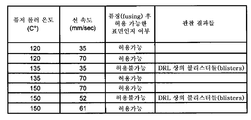
Figure 4 shows corresponding observations of the test conditions used in the test fuser and the quality of the surface of the dye receiving layers.
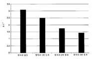
Figure 5 shows test results of a dye receiving layer under heat treatment according to embodiments of the present invention.
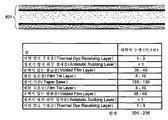
Figure 6 shows a dual receiver layer structure with thicknesses.
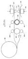
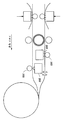
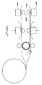
프린팅을 위한 바람직한 방법 및 장치가 본원에 상세히 설명되어 있고, 도 2에 도시되어 있으며, 도 1에 공통된 구성요소들은 상술한 것처럼 작동 가능하다. 상술한 것처럼 프린트 매체 면 A 상에 프린팅을 완료한 후, 상기 프린트 매체가 상기 공급 롤(106)을 향해 집어 넣어지면서, 가압 롤러(103a)는 가열된 롤러(108)에 대해 상기 프린트 매체를 가압할 것이고 열과 압력의 조합은 상기 드라이브 롤러(105)에 의해 남겨진 면 B 표면의 함몰된 점들의 크기를 감소시킬 것이다. 또한 상기 프린터는 본원에 설명된 것과 같이 반전 시퀀스에서 작동 가능하며 면 B가 먼저 프린트되고 드라이브 롤러(105)에 의해 형성된 면 A 함몰부들은 가압 롤러(103b) 및 가열된 롤러(108) 사이에서 압축에 의해 감소된다. 도 2는 가열된 롤러(108)와 닙을 형성하는 가압 롤러(103a)를 도시하나, 가압 롤러들(103a, 103b)은 모두 필요에 따라 그것과 함께 닙을 형성하기 위해 가열된 롤러(108)에 대한 위치로 그리고 상기 위치로부터 이동 가능하다. 상기 가열 롤러는 가열을 위해 상기 롤러를 통해 통과하는 전류를 이용하는 전자사진식 프린터들에서 이용되는 퓨저 롤러(fuser roller)와 유사하며 또는, 다른 바람직한 실시예(도 3a 및 도 3b)에서, 상기 가열 장치들은 유일한 목적이 프린팅 매체 표면을 매끄럽게 하는 플래턴 롤러들(203) 및 2개의 추가적인 서멀 프린트 헤드들(208)을 포함한다. 만약 도 3a에 도시된 것과 같이 또는 도 3b에 도시된 것과 같이 배치된 경우 상기 가열 장치들은 본 발명에 따라 상기 프린팅 매체를 치유(heal)하기 위해 작동 가능하다.Preferred methods and apparatus for printing are described in detail herein, and are shown in Figure 2, and the components common to Figure 1 are operable as described above. After completion of printing on the print medium surface A as described above, the pressurizing roller 103a presses the print medium against the
도 3b를 참조로, 상술한 것과 같이 프린트 매체 면A 상에 프린팅이 완료된 후, 앞서와 같이 상기 프린트 매체는 상기 공급 롤을 향해 집어 넣어지고, 그 다음에 파선에 의해 표시된 경로를 따라 전환된다. 상기 캡스턴 및 핀치 롤러는 상기 프린트 매체의 한 길이가 상기 프린트 헤드를 넘어 연장하도록 상기 프린트 헤드 및 플래턴 롤러 사이에서 상기 프린트 매체를 구동한다. 이것은 서멀 프린팅 단계 동안, 상기 프린트 매체가, 도면들에서 도시된 바와 같이, 왼쪽에서 오른쪽으로 당겨지기 때문이다. 이 시점에서, 상기 프린트 매체가 상기 프린트헤드 및 플래턴 롤러를 넘어 연장되고 프린팅을 위해 상기 프린트헤드를 향해 당겨지는 동안, 상기 가압 롤러(303b)는 가열된 롤러(308b)에 대해 상기 프린트 매체를 가압할 것이고 열과 압력의 조합은 상기 드라이브 롤러에 의해 남겨진 면 B 표면의 함몰된 점들의 크기를 감소시킬 것이다. 또한 상기 프린터는 반전 시퀀스(reverse sequence)에서 작동 가능하며 면 B가 먼저 프린트되고 상기 드라이브 롤러에 의해 형성된 면 A 함몰부들은 면 A를 프린팅하기 전에 가압 롤러(303a) 및 가열된 롤러(308a) 사이에서 압축에 의해 감소된다. Referring to FIG. 3B, after the printing on the print medium surface A is completed as described above, the print medium is pushed toward the supply roll as described above, and then switched along the path indicated by the dashed line. The capstan and pinch roller drive the print media between the print head and the platen roller such that a length of the print media extends beyond the print head. This is because during the thermal printing step, the print medium is pulled from left to right, as shown in the figures. At this point, while the print medium extends past the print head and the planar rollers and is pulled toward the print head for printing, the pressure roller 303b is rotated about the print medium 308b against the heated roller 308b And the combination of heat and pressure will reduce the size of the recessed points of the surface B left by the drive roller. The printer is also operable in an inverse sequence and the surface B is printed first and the surface A depressions formed by the drive roller are placed between the pressure roller 303a and the heated roller 308a before printing the surface A. [ Lt; / RTI >
상술한 프린팅 동작 동안, 구멍들, 함몰부들, 천공부들, 또는 오목부들이 프린트되는 면에 대향하는 면 상에 상기 캡스턴 롤러에 의해 생성되는 것이 실험을 통해 알려져 있다. 이러한 구멍들은 외곽의 염료 수용기 층(dye receiver layer;DRL)에 초승달 형상의 오목부들이다. 매체의 유형에 따라, 이러한 구멍들은 DRL을 관통할 수 있어서 DRL에 천공부들을 야기한다. 상기 DRL은 유연한 층이어서, 상기 드라이브 롤러에 의해 오목해지거나 천공될 수 있다. 상기 DRL이 상기 드라이브 롤러에 의해 오목해지거나 천공되거나, 상기 가열하는 단계는 상기 염료 도너를 수용하기 위한 상기 DRL 표면을 개선시키고 개선된 프린트 품질이 된다. 일부 이중 서멀 프린터 디자인들은 질감이 나는 드라이브 롤러가 없이 구상된다는 것을 주목해야 한다. 오히려, 상기 드라이브 롤러 상에 거친 질감의 결여 때문에 상실한 견인력을 보상하기 위해 매끄러운 드라이브 롤러가 상기 핀치 롤러에 대해 증가된 압력으로 이용된다. 이러한 증가된 압력은 또한 이중 수용기에 함몰부들 또는 오목부들, 즉 자국들(tracks),을 유발할 수 있어서 페이지를 가로질러 밀도 차이들의 결과가 된다. 본원에 개시된 발명의 실시예들은 또한 이러한 차이들을 정정하는 역할을 한다.It has been experimentally known that during the printing operation described above, holes, depressions, perforations, or recesses are produced by the capstan roller on a surface facing the side to be printed. These holes are crescent-shaped recesses in the outer dye receiver layer (DRL). Depending on the type of media, these holes can penetrate the DRL and cause the DRL to be punched. The DRL is a flexible layer, which can be recessed or perforated by the drive roller. The DRL is recessed or perforated by the drive roller and the heating improves the DRL surface for receiving the dye donor and provides improved print quality. It should be noted that some dual thermal printer designs are visualized without textured drive rollers. Rather, a smooth drive roller is used at an increased pressure on the pinch roller to compensate for the lost traction force due to lack of coarse texture on the drive roller. This increased pressure can also cause depressions or depressions, or tracks, in the dual receiver, resulting in density differences across the page. Embodiments of the invention disclosed herein also serve to correct for these differences.
도 6을 참조로, 본 발명의 바람직한 실시예로 고려된 상기 이중 수용기 구조(601)에서 다양한 층들의 두께들이 도시되어 있다. 다른 이중 수용기 재료들은 본 발명의 실시예들을 이용하여 유사하게 개선될 수 있다. 상기 질감이 나는 드라이브 롤러는 일반적으로 그 실린더형 표면으로부터 약 25미크론(micron)의 거리로 연장된 돌출부들을 포함한다.Referring to Figure 6, the thicknesses of the various layers in the
이러한 손상된 DRL 표면이 프린트될 때 상기 캡스턴 롤러에 대응하는 영역들에서 상기 프린트 밀도는 상기 프린트의 나머지에서 발견되는 프린트 밀도보다 낮다. 그것은 상기 구멍들이 서멀 프린팅 단계에 의해 의도대로 염료로 채워지지 않고 그런 이유로 하프톤 효과(half tone effect)가 가시적으로 낮은 프린트 밀도의 결과가 된다고 추측(되었고 현미경으로 관찰)되었다. 공백이 있는(voided) 두 개의 축으로 지향된 폴리프로필렌 라미네이트(polypropylene laminate)를 포함하는 양면 서멀 수용기 (매체)는 테스트 목적들을 위해 한 번만 사용하였다. 한번 사용은 상기 수용기가 프린팅 없이 한번 상기 캡스턴 롤러들을 통해 당겨지거나 구동되었다는 것을 의미한다. 실험들은 상기 캡스턴 롤러에 노출된 프린트되지 않은 DRL 표면 상에 열 처리의 효과를 평가하였다. 상기 열처리는 전자사진식 퓨저 브레드보드(electrophotographic fuser breadboard)를 이용하여 적용되었다. 이러한 브레드보드는 온도 및 라인 속도(line speed)를 상기 가열된 롤러(108) 및 가압 롤러(103a 또는 103b)에 의해 형성된 닙, 탄성중합체 닙(elastomer nip), 사이에서 일정한 압력에서 변화시킬 수 있도록 허용한다. 압력 감응 매체를 이용하여 상기 측정된 닙 폭은 5mm였다. 이러한 폭은 상기 프린트 매체를 따라 길이방향으로(lengthwise) 측정되고 순응 가압 롤러에 대한 상기 가열된 롤러의 압력에 의해 그 사이에 상기 프린트 매체를 갖고 형성된다. 증가된 압력은 더 큰 직경의 가열된 롤러, 더 큰 직경의 순응 가압 롤러, 또는 만약 롤러가 더 순응되도록 만들어지는 것과 같이 닙 폭을 증가시킨다. 증가된 닙 폭은 상기 프린트 매체로 전달된 열량을 증가시킨다. 일반적인 가압 롤러들은 두꺼운 실리콘 러버 층, 및 외곽 층으로서 얇은 테플론 코팅을 갖는 스틸 코어이다. 상기 가열된 롤러는 대부분의 전자사진식 프린터들에서 이용되는 퓨저 롤러와 디자인이 유사하다.The print density in areas corresponding to the capstan roller when such a damaged DRL surface is printed is lower than the print density found in the remainder of the print. It was hypothesized that the holes would not be filled with the dye as intended by the thermal printing step and that the half tone effect would result in a visually low print density (and was observed under a microscope). Two-sided thermal receptors (media) containing two axially oriented polypropylene laminates with voided voids were used only once for testing purposes. One use means that the receptacle was pulled or driven through the capstan rollers once without printing. Experiments have evaluated the effect of heat treatment on unprinted DRL surfaces exposed to the capstan rollers. The heat treatment was applied using an electrophotographic fuser breadboard. This breadboard can be used to change the temperature and line speed at a constant pressure between the nip formed by the
각각의 변화의 10 피트는 상기 프린터에서 가열된 캡스턴 롤러에 노출된 DRL 면을 테스팅하는 것이 가능하도록 생성되었다. 관찰들은 도 4에 도시된 것과 같이 기록되었다. 주어진 온도 및 라인 속도 조건(예를 들어, 150 C, 70 mm/sec)에 대해 상기 프린트 매체(수용기)는 두 번 움직였고 세 번 상기 닙을 지났다. 우리는 상기 매체를 10 mm 닙 폭에 노출시키는 것과 동등하도록 상기 매체를 5mm 닙을 두 번 지나는 것(상기 수용기를 가열 단계들 사이에서 냉각시켜야 하기 때문에 비연속 방법을 통해)과 15mm 닙 폭에 노출시키는 것과 동등하도록 세 번 지나는 것(상술한 것과 같이 비연속 방법을 통해)을 고려한다. 도 5는 상기 프린트 매체의 캡스턴 롤러로 손상된 영역과 상기 프린트 매체의 캡스턴-접촉되지 않은 부분 사이에서 델타 L* (ΔL*)의 차이를 강조한다. L*는 밝기의 임의의 상대 측정이고 도 5의 그래프에서 도시된 L*의 변화들은 다른 측정된 규모들에 대해 해석되어야 한다. 상기 규모들은 농도계(densitometer)를 이용하여 측정된다. 열 처리된 샘플들(150℃, 70 mm/s)은 더 낮은 ΔL*을 보인다는 것, 즉 접촉되지 않은 매체와 캡스턴 손상된 매체 사이의 가시적 차이가 더 적음이 관찰된다.Ten feet of each change was created to allow testing of the DRL surface exposed to the heated capstan rollers in the printer. Observations were recorded as shown in FIG. For a given temperature and line speed conditions (e.g., 150 C, 70 mm / sec), the print medium (receiver) moved twice and passed the nip three times. We used the medium to pass through the 5mm nip twice (through the discontinuous process because the receiver had to be cooled between the heating steps) to expose the medium to a 15mm nip width to equal the exposure of the medium to 10mm nip width (Through the non-continuous method as described above) to be equal to the number of times it is performed. Figure 5 highlights the difference in delta L * ([Delta] L *) between the area damaged by the capstan rollers of the print medium and the capstan-free part of the print medium. L * is an arbitrary relative measurement of brightness and the changes in L * shown in the graph of Figure 5 should be interpreted for different measured magnitudes. The scales are measured using a densitometer. It is observed that the heat treated samples (150 캜, 70 mm / s) show lower ΔL *, ie, less visible difference between untouched media and capstan-damaged media.
열 처리는 상기 캡스턴 롤러 표시들을 치유하고 ΔL*을 최소화하는 가능성을 보여준다. 이 과정에서의 개선들은 치유 공정들이 가능하게 상기 닙에서 압력을 변화시키는, 또는 상기 구멍들을 치유하는 서멀 헤드를 이용하는 능력을 포함할 수 있다(도 3). 다른 가열 방법들은 상기 캡스턴 롤러와 상기 공급 롤 사이에 위치된 가열 영역을 포함한다. 상기 가열 영역은 DRL에 밀착하지 않는 가열된 밴드를 포함할 수 있다. 상기 가열 영역은 또한 비-접촉 가열원을 포함할 수 있다.The heat treatment shows the possibility of healing the capstan roller marks and minimizing? L *. Improvements in this process may include the ability to utilize the thermal head to change the pressure in the nip, or to heal the holes, so that healing processes are possible (FIG. 3). Other heating methods include a heating zone positioned between the capstan roller and the feed roll. The heating zone may comprise a heated band that is not in intimate contact with the DRL. The heating region may also include a non-contact heating source.
상기 서멀 염료 수용기 매체는 이중 서멀 수용기들을 위해 다양한 잘 알려진 기술들 및 재료들에 의해 제조될 수 있다. 바람직한 발명 및 재료들은 상기 프린트 매체의 비-이미지 반전 면의 설명들에 대한 것을 제외하고 그 전체로서 참조로 본원에 병합되는, 미국 특허 출원공개 제 2011/0091667호 A1에 설명되어 있다.The thermal dye receptor medium can be made by a variety of well known techniques and materials for dual thermal receptors. Preferred inventions and materials are described in U.S. Patent Application Publication No. 2011/0091667 Al, incorporated herein by reference in its entirety, except for the descriptions of non-image reversal surfaces of the print media.
101 도너 (Donor)
102 서멀 프린트 헤드
103a 순응 가압 롤러
103b 순응 가압 롤러
104 핀치 롤러
105 캡스턴 롤러
106 종이 (매체) 롤
107 핀치 롤러
108 가열된 롤러
109 서멀 프린트 헤드
110 도너
111 플래턴 롤러
112 플래턴 롤러
203 플래턴 롤러들
208 서멀 헤드들101 Donor
102 Thermal Print Head
103a conforming pressure roller
103b conforming pressure roller
104 Pinch roller
105 capstan rollers
106 paper (medium) rolls
107 Pinch roller
108 Heated roller
109 Thermal Print Head
110 donor
111 Platen roller
112 Platen roller
203 Platen Roller
208 Thermal heads
Claims (20)
상기 프린터를 이용하여 상기 매체의 제1 면 상에 프린팅하는 단계와,
상기 매체의 제2 면을 매끄럽게 하는 단계(smoothing)와,
상기 프린터를 이용하여 상기 매체의 상기 제2 면 상에 프린팅하는 단계를 포함하는,
프린팅 방법.Receiving a double-sided medium in a printer,
Printing on the first side of the medium using the printer;
Smoothing the second side of the medium,
And printing on the second side of the medium using the printer.
Printing method.
상기 매끄럽게 하는 단계는 상기 제1 면 상에 프린팅하는 단계 후에 그리고 상기 매체가 상기 프린터 내에 유지되는 동안 상기 매체의 상기 제2 면을 가열하는 단계를 포함하는,
프린팅 방법.The method according to claim 1,
Wherein the smoothing step comprises heating the second side of the medium after printing on the first side and while the medium is held in the printer.
Printing method.
상기 가열하는 단계는 가열된 표면에 대해 상기 매체를 압축하는 단계(compressing)를 포함하는,
프린팅 방법.3. The method of claim 2,
Wherein said heating comprises compressing said medium against a heated surface.
Printing method.
상기 압축하는 단계는 가열된 롤러를 이용하는 단계를 포함하는,
프린팅 방법.The method of claim 3,
Wherein said compressing comprises using a heated roller.
Printing method.
상기 가열된 롤러를 이용하는 단계는 복수의 롤러들을 이용하는 단계를 포함하며, 상기 복수의 롤러들 중 적어도 하나는 가열되는,
프린팅 방법.5. The method of claim 4,
Wherein the step of using the heated roller includes using a plurality of rollers, at least one of the plurality of rollers being heated,
Printing method.
상기 복수의 롤러들을 이용하는 단계는 상기 복수의 롤러들 중 적어도 두 개 사이에서 상기 매체를 압축하는 단계를 포함하며, 상기 적어도 두 개의 롤러들 중 적어도 하나는 가열되는,
프린팅 방법.6. The method of claim 5,
Wherein using the plurality of rollers comprises compressing the medium between at least two of the plurality of rollers, at least one of the at least two rollers being heated,
Printing method.
상기 가열된 표면을 통해 전류를 통과시킴에 의해 가열하는 단계를 더 포함하는,
프린팅 방법.The method of claim 3,
And heating by passing an electric current through the heated surface.
Printing method.
상기 매체가 상기 가열된 표면에 대해 압축되는 동안 상기 가열된 표면을 통해 전류를 통과시키는 단계를 더 포함하는,
프린팅 방법.8. The method of claim 7,
Further comprising passing current through the heated surface while the medium is compressed against the heated surface,
Printing method.
서멀 프린트 헤드를 이용하는 것을 포함하여 상기 이중 프린팅 매체의 제2 면 상에 프린팅하는 단계와,
상기 질감이 나는 롤러에 의해 유발된 상기 이중 프린팅 매체의 상기 제1 면에 오목부들의 크기가 감소되는, 상기 이중 프린팅 매체의 상기 제1 면을 매끄럽게 하는 단계와,
상기 매끄럽게 하는 단계 후에 상기 이중 프린팅 매체의 상기 제1 면 상에 프린팅하는 단계를 포함하는,
프린팅 방법.Receiving the dual printing medium within the printer, including using a textured roller that is pressed against a first side of the double printing medium to draw the dual printing medium into the printer,
Printing on a second side of the double printing medium, including using a thermal print head;
Smoothing the first surface of the double-printing medium, wherein the size of the recesses on the first surface of the double-printing medium caused by the textured roller is reduced,
And printing on the first side of the double-printing medium after the smoothing step.
Printing method.
상기 매끄럽게 하는 단계는 상기 이중 프린팅 매체의 상기 제2 면 상에 프린팅하는 단계 후에 상기 이중 프린팅 매체의 상기 제1 면을 가열하는 단계를 포함하는,
프린팅 방법.10. The method of claim 9,
Wherein the smoothing step comprises heating the first side of the double printing medium after printing on the second side of the double printing medium.
Printing method.
상기 가열하는 단계는 가열된 표면에 대해 상기 이중 프린팅 매체를 압축하는 단계를 포함하는,
프린팅 방법.11. The method of claim 10,
Wherein said heating comprises compressing said double printing medium against a heated surface.
Printing method.
상기 압축하는 단계는 가열된 롤러를 이용하는 단계를 포함하는,
프린팅 방법.12. The method of claim 11,
Wherein said compressing comprises using a heated roller.
Printing method.
가열된 롤러를 이용하는 단계는 복수의 롤러들을 이용하는 단계를 포함하며, 상기 복수의 롤러들 중 적어도 하나는 가열되는,
프린팅 방법.13. The method of claim 12,
Wherein the step of using heated rollers comprises using a plurality of rollers, at least one of the plurality of rollers being heated,
Printing method.
상기 가열된 표면을 통해 전류를 통과시킴에 의해 상기 가열된 표면을 가열하는 단계를 더 포함하는,
프린팅 방법.12. The method of claim 11,
Heating the heated surface by passing an electric current through the heated surface,
Printing method.
상기 이중 프린팅 매체가 상기 가열된 표면에 대해 압축되는 동안 상기 가열된 표면을 통해 전류를 통과시키는 단계를 더 포함하는,
프린팅 방법.15. The method of claim 14,
Further comprising passing current through the heated surface while the double printing medium is compressed against the heated surface,
Printing method.
상기 프린팅 매체를 당기는 단계 후에 상기 프린팅 매체의 일 면을 매끄럽게 하는 단계를 포함하는,
프린팅 매체 취급 방법.A nip formed between the textured capstan roller and the pinch roller which impairs the ability of one side of the printing medium to receive the donor dye applied by the thermal print head by forming a plurality of recesses on one side of the printing medium. Pulling the printing medium through the printing medium,
And smoothing one side of the printing medium after the step of pulling the printing medium.
Printing medium handling method.
상기 매끄럽게 하는 단계는 상기 프린팅 매체의 상기 일 면을 가열하는 단계를 포함하는,
프린팅 매체 취급 방법.17. The method of claim 16,
Wherein the smoothing step comprises heating the one side of the printing medium.
Printing medium handling method.
상기 가열하는 단계는 핀치 롤러 및 가열된 롤러에 의해 형성된 닙을 통해 상기 프린팅 매체를 당기는 단계를 포함하는,
프린팅 매체 취급 방법.18. The method of claim 17,
Wherein the heating step includes pulling the printing medium through a nip formed by a pinch roller and a heated roller.
Printing medium handling method.
상기 가열된 롤러는 그것을 통해 전류를 통과시킴에 의해 가열되는,
프린팅 매체 취급 방법.19. The method of claim 18,
The heated roller being heated by passing an electric current therethrough,
Printing medium handling method.
상기 핀치 롤러 및 상기 가열된 롤러에 의해 형성된 상기 닙을 통해 상기 프린팅 매체를 당기는 단계 동안 상기 가열된 롤러를 통해 전류를 통과시키는 단계를 더 포함하는,
프린팅 매체 취급 방법.20. The method of claim 19,
Further comprising passing current through the heated roller during the step of pulling the printing medium through the nip formed by the pinch roller and the heated roller.
Printing medium handling method.
Applications Claiming Priority (3)
| Application Number | Priority Date | Filing Date | Title |
|---|---|---|---|
| US13/422,045 | 2012-03-16 | ||
| US13/422,045 US8743163B2 (en) | 2012-03-16 | 2012-03-16 | Printing method for reducing printer artifacts |
| PCT/US2013/031135 WO2013138543A1 (en) | 2012-03-16 | 2013-03-14 | Printing method for reducing printer artifacts |
Publications (1)
| Publication Number | Publication Date |
|---|---|
| KR20140136038A true KR20140136038A (en) | 2014-11-27 |
Family
ID=48048198
Family Applications (1)
| Application Number | Title | Priority Date | Filing Date |
|---|---|---|---|
| KR20147028713A KR20140136038A (en) | 2012-03-16 | 2013-03-14 | Printing method for reducing printer artifacts |
Country Status (7)
| Country | Link |
|---|---|
| US (2) | US8743163B2 (en) |
| EP (1) | EP2825390B1 (en) |
| JP (1) | JP2015511898A (en) |
| KR (1) | KR20140136038A (en) |
| CN (2) | CN104169096B (en) |
| IN (1) | IN2014DN07546A (en) |
| WO (1) | WO2013138543A1 (en) |
Families Citing this family (5)
| Publication number | Priority date | Publication date | Assignee | Title |
|---|---|---|---|---|
| US8749604B2 (en) * | 2012-03-16 | 2014-06-10 | Kodak Alaris Inc. | Printing system for reducing printer artifacts |
| US8743163B2 (en) * | 2012-03-16 | 2014-06-03 | Kodak Alaris Inc. | Printing method for reducing printer artifacts |
| US8599229B1 (en) * | 2012-06-26 | 2013-12-03 | Kodak Alaris Inc. | Roll-fed duplex thermal printing system |
| JP5996469B2 (en) * | 2013-03-28 | 2016-09-21 | シチズンホールディングス株式会社 | Printer |
| KR102405721B1 (en) * | 2015-10-02 | 2022-06-03 | 아싸 아블로이 아베 | Card substrate laminating device |
Family Cites Families (19)
| Publication number | Priority date | Publication date | Assignee | Title |
|---|---|---|---|---|
| GB2117707B (en) * | 1982-02-17 | 1985-07-10 | Tokyo Shibaura Electric Co | Thermal transfer type printing apparatus |
| JPS58140275A (en) * | 1982-02-17 | 1983-08-19 | Toshiba Corp | Printer |
| JPS59155081A (en) * | 1983-02-23 | 1984-09-04 | Hitachi Ltd | Thermal recorder |
| JPS61173957A (en) * | 1985-01-29 | 1986-08-05 | Citizen Watch Co Ltd | Thermal transfer printer |
| JPS61206683A (en) * | 1985-03-12 | 1986-09-12 | Yokogawa Electric Corp | Thermal transfer printer |
| US5284816A (en) * | 1992-11-19 | 1994-02-08 | Eastman Kodak Company | Two-sided thermal printing system |
| JP2000296607A (en) * | 1999-04-16 | 2000-10-24 | Mutoh Ind Ltd | Ink jet printer |
| US6361228B1 (en) * | 1999-05-27 | 2002-03-26 | Printronix, Inc. | Thermal printer with improved ribbon transport |
| US6784906B2 (en) * | 2001-12-18 | 2004-08-31 | Ncr Corporation | Direct thermal printer |
| EP1557266A4 (en) * | 2003-04-18 | 2005-07-27 | Mimaki Eng Kk | Ink jet printer |
| CN1880097A (en) * | 2005-06-15 | 2006-12-20 | 金宝电子工业股份有限公司 | Paper feeding module for double face printing, and double face printing method |
| US20070120942A1 (en) * | 2005-11-30 | 2007-05-31 | Ncr Corporation | Dual-sided two color thermal printing |
| CN2925872Y (en) * | 2006-07-25 | 2007-07-25 | 李新忠 | Satellite printer with double printing |
| US8848010B2 (en) * | 2007-07-12 | 2014-09-30 | Ncr Corporation | Selective direct thermal and thermal transfer printing |
| WO2010055923A1 (en) * | 2008-11-14 | 2010-05-20 | 大日本印刷株式会社 | Duplex printing method, bookbinding method, printer for use in duplex printing method |
| JP2011046156A (en) * | 2009-08-28 | 2011-03-10 | Sinfonia Technology Co Ltd | Thermal printer and printing method |
| JP5043984B2 (en) * | 2010-05-10 | 2012-10-10 | キヤノン株式会社 | Printing apparatus and installation method of printing apparatus |
| US8743163B2 (en) * | 2012-03-16 | 2014-06-03 | Kodak Alaris Inc. | Printing method for reducing printer artifacts |
| US8749604B2 (en) * | 2012-03-16 | 2014-06-10 | Kodak Alaris Inc. | Printing system for reducing printer artifacts |
-
2012
- 2012-03-16 US US13/422,045 patent/US8743163B2/en active Active
-
2013
- 2013-03-14 CN CN201380014723.0A patent/CN104169096B/en not_active Expired - Fee Related
- 2013-03-14 CN CN201710030812.4A patent/CN107053865B/en not_active Expired - Fee Related
- 2013-03-14 EP EP13714395.4A patent/EP2825390B1/en active Active
- 2013-03-14 KR KR20147028713A patent/KR20140136038A/en not_active Application Discontinuation
- 2013-03-14 IN IN7546DEN2014 patent/IN2014DN07546A/en unknown
- 2013-03-14 WO PCT/US2013/031135 patent/WO2013138543A1/en active Application Filing
- 2013-03-14 JP JP2015500587A patent/JP2015511898A/en active Pending
-
2014
- 2014-04-22 US US14/258,697 patent/US9056487B2/en active Active
Also Published As
| Publication number | Publication date |
|---|---|
| CN107053865B (en) | 2018-12-21 |
| JP2015511898A (en) | 2015-04-23 |
| US8743163B2 (en) | 2014-06-03 |
| US20130242027A1 (en) | 2013-09-19 |
| EP2825390A1 (en) | 2015-01-21 |
| CN104169096B (en) | 2017-02-22 |
| US9056487B2 (en) | 2015-06-16 |
| WO2013138543A1 (en) | 2013-09-19 |
| EP2825390B1 (en) | 2016-03-09 |
| CN104169096A (en) | 2014-11-26 |
| IN2014DN07546A (en) | 2015-04-24 |
| CN107053865A (en) | 2017-08-18 |
| US20140267532A1 (en) | 2014-09-18 |
Similar Documents
| Publication | Publication Date | Title |
|---|---|---|
| US20140267536A1 (en) | Printing system for reducing printer artifacts | |
| US9056487B2 (en) | Printing method for reducing printer artifacts | |
| KR20170044083A (en) | Intermediate transfer film having substantially transparent alignment marks | |
| JP2018126925A (en) | Printer and printer control program | |
| US10603897B2 (en) | Ink splitting multi-roll cleaner for a variable data lithography system | |
| JP4649758B2 (en) | Inkjet recording device | |
| US10668716B2 (en) | Transfer film having a roller cleaning section | |
| EP1947529A3 (en) | Fusing Device and Image Forming Apparatus using the Same | |
| JP2004188694A (en) | Ink sheet for image printing device, laminated sheet and image printing device | |
| JP2003241561A (en) | Method and apparatus for forming image | |
| EP1752294A3 (en) | Printer | |
| JP2010058445A (en) | Stamping apparatus | |
| JP4343422B2 (en) | Heating apparatus and image forming apparatus | |
| JP2017077927A (en) | Medium transportation mechanism | |
| JP2011081237A (en) | Fixing device | |
| JPH08192547A (en) | Printing paper carrying device for printer | |
| JP5901309B2 (en) | Printing device | |
| JP2007260768A (en) | Embossing equipment | |
| JP2005162470A (en) | Roll paper feeder and recording apparatus | |
| JP2004243738A (en) | Stencil printing device | |
| JP2022013374A (en) | Cleaning cassette and thermal printer | |
| JP2007307861A5 (en) | ||
| JP2001138557A (en) | Method and apparatus for imaging | |
| JP2016087950A (en) | Double-side stencil printing device and ink adjustment method of the same | |
| JP2006189635A (en) | Fixing device |
Legal Events
| Date | Code | Title | Description |
|---|---|---|---|
| WITN | Application deemed withdrawn, e.g. because no request for examination was filed or no examination fee was paid |