JP2015500778A - Plastic container for pressure-packing filled products and method of manufacturing the same - Google Patents
Plastic container for pressure-packing filled products and method of manufacturing the same Download PDFInfo
- Publication number
- JP2015500778A JP2015500778A JP2014545048A JP2014545048A JP2015500778A JP 2015500778 A JP2015500778 A JP 2015500778A JP 2014545048 A JP2014545048 A JP 2014545048A JP 2014545048 A JP2014545048 A JP 2014545048A JP 2015500778 A JP2015500778 A JP 2015500778A
- Authority
- JP
- Japan
- Prior art keywords
- container
- pressure
- preform
- pressure vessel
- plastic
- Prior art date
- Legal status (The legal status is an assumption and is not a legal conclusion. Google has not performed a legal analysis and makes no representation as to the accuracy of the status listed.)
- Pending
Links
Images


Classifications
-
- B—PERFORMING OPERATIONS; TRANSPORTING
- B65—CONVEYING; PACKING; STORING; HANDLING THIN OR FILAMENTARY MATERIAL
- B65D—CONTAINERS FOR STORAGE OR TRANSPORT OF ARTICLES OR MATERIALS, e.g. BAGS, BARRELS, BOTTLES, BOXES, CANS, CARTONS, CRATES, DRUMS, JARS, TANKS, HOPPERS, FORWARDING CONTAINERS; ACCESSORIES, CLOSURES, OR FITTINGS THEREFOR; PACKAGING ELEMENTS; PACKAGES
- B65D11/00—Containers having bodies formed by interconnecting or uniting two or more rigid, or substantially rigid, components made wholly or mainly of plastics material
- B65D11/02—Containers having bodies formed by interconnecting or uniting two or more rigid, or substantially rigid, components made wholly or mainly of plastics material of curved cross-section
- B65D11/04—Bottles or similar containers with necks or like restricted apertures designed for pouring contents
-
- B—PERFORMING OPERATIONS; TRANSPORTING
- B65—CONVEYING; PACKING; STORING; HANDLING THIN OR FILAMENTARY MATERIAL
- B65D—CONTAINERS FOR STORAGE OR TRANSPORT OF ARTICLES OR MATERIALS, e.g. BAGS, BARRELS, BOTTLES, BOXES, CANS, CARTONS, CRATES, DRUMS, JARS, TANKS, HOPPERS, FORWARDING CONTAINERS; ACCESSORIES, CLOSURES, OR FITTINGS THEREFOR; PACKAGING ELEMENTS; PACKAGES
- B65D83/00—Containers or packages with special means for dispensing contents
- B65D83/14—Containers or packages with special means for dispensing contents for delivery of liquid or semi-liquid contents by internal gaseous pressure, i.e. aerosol containers comprising propellant for a product delivered by a propellant
- B65D83/60—Contents and propellant separated
- B65D83/66—Contents and propellant separated first separated, but finally mixed, e.g. in a dispensing head
- B65D83/663—Contents and propellant separated first separated, but finally mixed, e.g. in a dispensing head at least a portion of the propellant being separated from the product and incrementally released by means of a pressure regulator
-
- B—PERFORMING OPERATIONS; TRANSPORTING
- B29—WORKING OF PLASTICS; WORKING OF SUBSTANCES IN A PLASTIC STATE IN GENERAL
- B29D—PRODUCING PARTICULAR ARTICLES FROM PLASTICS OR FROM SUBSTANCES IN A PLASTIC STATE
- B29D22/00—Producing hollow articles
- B29D22/003—Containers for packaging, storing or transporting, e.g. bottles, jars, cans, barrels, tanks
-
- B—PERFORMING OPERATIONS; TRANSPORTING
- B65—CONVEYING; PACKING; STORING; HANDLING THIN OR FILAMENTARY MATERIAL
- B65D—CONTAINERS FOR STORAGE OR TRANSPORT OF ARTICLES OR MATERIALS, e.g. BAGS, BARRELS, BOTTLES, BOXES, CANS, CARTONS, CRATES, DRUMS, JARS, TANKS, HOPPERS, FORWARDING CONTAINERS; ACCESSORIES, CLOSURES, OR FITTINGS THEREFOR; PACKAGING ELEMENTS; PACKAGES
- B65D11/00—Containers having bodies formed by interconnecting or uniting two or more rigid, or substantially rigid, components made wholly or mainly of plastics material
- B65D11/16—Containers having bodies formed by interconnecting or uniting two or more rigid, or substantially rigid, components made wholly or mainly of plastics material with double walls
-
- B—PERFORMING OPERATIONS; TRANSPORTING
- B65—CONVEYING; PACKING; STORING; HANDLING THIN OR FILAMENTARY MATERIAL
- B65D—CONTAINERS FOR STORAGE OR TRANSPORT OF ARTICLES OR MATERIALS, e.g. BAGS, BARRELS, BOTTLES, BOXES, CANS, CARTONS, CRATES, DRUMS, JARS, TANKS, HOPPERS, FORWARDING CONTAINERS; ACCESSORIES, CLOSURES, OR FITTINGS THEREFOR; PACKAGING ELEMENTS; PACKAGES
- B65D11/00—Containers having bodies formed by interconnecting or uniting two or more rigid, or substantially rigid, components made wholly or mainly of plastics material
- B65D11/20—Details of walls made of plastics material
- B65D11/22—Reinforcing for strengthening parts of members
- B65D11/26—Local reinforcements, e.g. adjacent to closures
-
- B—PERFORMING OPERATIONS; TRANSPORTING
- B65—CONVEYING; PACKING; STORING; HANDLING THIN OR FILAMENTARY MATERIAL
- B65D—CONTAINERS FOR STORAGE OR TRANSPORT OF ARTICLES OR MATERIALS, e.g. BAGS, BARRELS, BOTTLES, BOXES, CANS, CARTONS, CRATES, DRUMS, JARS, TANKS, HOPPERS, FORWARDING CONTAINERS; ACCESSORIES, CLOSURES, OR FITTINGS THEREFOR; PACKAGING ELEMENTS; PACKAGES
- B65D83/00—Containers or packages with special means for dispensing contents
- B65D83/14—Containers or packages with special means for dispensing contents for delivery of liquid or semi-liquid contents by internal gaseous pressure, i.e. aerosol containers comprising propellant for a product delivered by a propellant
- B65D83/38—Details of the container body
-
- B—PERFORMING OPERATIONS; TRANSPORTING
- B65—CONVEYING; PACKING; STORING; HANDLING THIN OR FILAMENTARY MATERIAL
- B65D—CONTAINERS FOR STORAGE OR TRANSPORT OF ARTICLES OR MATERIALS, e.g. BAGS, BARRELS, BOTTLES, BOXES, CANS, CARTONS, CRATES, DRUMS, JARS, TANKS, HOPPERS, FORWARDING CONTAINERS; ACCESSORIES, CLOSURES, OR FITTINGS THEREFOR; PACKAGING ELEMENTS; PACKAGES
- B65D83/00—Containers or packages with special means for dispensing contents
- B65D83/14—Containers or packages with special means for dispensing contents for delivery of liquid or semi-liquid contents by internal gaseous pressure, i.e. aerosol containers comprising propellant for a product delivered by a propellant
- B65D83/42—Filling or charging means
-
- B—PERFORMING OPERATIONS; TRANSPORTING
- B65—CONVEYING; PACKING; STORING; HANDLING THIN OR FILAMENTARY MATERIAL
- B65D—CONTAINERS FOR STORAGE OR TRANSPORT OF ARTICLES OR MATERIALS, e.g. BAGS, BARRELS, BOTTLES, BOXES, CANS, CARTONS, CRATES, DRUMS, JARS, TANKS, HOPPERS, FORWARDING CONTAINERS; ACCESSORIES, CLOSURES, OR FITTINGS THEREFOR; PACKAGING ELEMENTS; PACKAGES
- B65D83/00—Containers or packages with special means for dispensing contents
- B65D83/14—Containers or packages with special means for dispensing contents for delivery of liquid or semi-liquid contents by internal gaseous pressure, i.e. aerosol containers comprising propellant for a product delivered by a propellant
- B65D83/60—Contents and propellant separated
- B65D83/62—Contents and propellant separated by membrane, bag, or the like
-
- B—PERFORMING OPERATIONS; TRANSPORTING
- B65—CONVEYING; PACKING; STORING; HANDLING THIN OR FILAMENTARY MATERIAL
- B65D—CONTAINERS FOR STORAGE OR TRANSPORT OF ARTICLES OR MATERIALS, e.g. BAGS, BARRELS, BOTTLES, BOXES, CANS, CARTONS, CRATES, DRUMS, JARS, TANKS, HOPPERS, FORWARDING CONTAINERS; ACCESSORIES, CLOSURES, OR FITTINGS THEREFOR; PACKAGING ELEMENTS; PACKAGES
- B65D83/00—Containers or packages with special means for dispensing contents
- B65D83/14—Containers or packages with special means for dispensing contents for delivery of liquid or semi-liquid contents by internal gaseous pressure, i.e. aerosol containers comprising propellant for a product delivered by a propellant
- B65D83/60—Contents and propellant separated
- B65D83/64—Contents and propellant separated by piston
-
- B—PERFORMING OPERATIONS; TRANSPORTING
- B29—WORKING OF PLASTICS; WORKING OF SUBSTANCES IN A PLASTIC STATE IN GENERAL
- B29C—SHAPING OR JOINING OF PLASTICS; SHAPING OF MATERIAL IN A PLASTIC STATE, NOT OTHERWISE PROVIDED FOR; AFTER-TREATMENT OF THE SHAPED PRODUCTS, e.g. REPAIRING
- B29C2949/00—Indexing scheme relating to blow-moulding
- B29C2949/30—Preforms or parisons made of several components
- B29C2949/3032—Preforms or parisons made of several components having components being injected
-
- B—PERFORMING OPERATIONS; TRANSPORTING
- B29—WORKING OF PLASTICS; WORKING OF SUBSTANCES IN A PLASTIC STATE IN GENERAL
- B29C—SHAPING OR JOINING OF PLASTICS; SHAPING OF MATERIAL IN A PLASTIC STATE, NOT OTHERWISE PROVIDED FOR; AFTER-TREATMENT OF THE SHAPED PRODUCTS, e.g. REPAIRING
- B29C2949/00—Indexing scheme relating to blow-moulding
- B29C2949/30—Preforms or parisons made of several components
- B29C2949/3041—Preforms or parisons made of several components having components being extruded
-
- B—PERFORMING OPERATIONS; TRANSPORTING
- B29—WORKING OF PLASTICS; WORKING OF SUBSTANCES IN A PLASTIC STATE IN GENERAL
- B29K—INDEXING SCHEME ASSOCIATED WITH SUBCLASSES B29B, B29C OR B29D, RELATING TO MOULDING MATERIALS OR TO MATERIALS FOR MOULDS, REINFORCEMENTS, FILLERS OR PREFORMED PARTS, e.g. INSERTS
- B29K2101/00—Use of unspecified macromolecular compounds as moulding material
-
- B—PERFORMING OPERATIONS; TRANSPORTING
- B65—CONVEYING; PACKING; STORING; HANDLING THIN OR FILAMENTARY MATERIAL
- B65D—CONTAINERS FOR STORAGE OR TRANSPORT OF ARTICLES OR MATERIALS, e.g. BAGS, BARRELS, BOTTLES, BOXES, CANS, CARTONS, CRATES, DRUMS, JARS, TANKS, HOPPERS, FORWARDING CONTAINERS; ACCESSORIES, CLOSURES, OR FITTINGS THEREFOR; PACKAGING ELEMENTS; PACKAGES
- B65D83/00—Containers or packages with special means for dispensing contents
- B65D83/14—Containers or packages with special means for dispensing contents for delivery of liquid or semi-liquid contents by internal gaseous pressure, i.e. aerosol containers comprising propellant for a product delivered by a propellant
- B65D83/38—Details of the container body
- B65D83/384—Details of the container body comprising an aerosol container disposed in an outer shell or in an external container
Abstract
充填製品連続体、とりわけ半液状流体、及び泡、ペースト、クリーム又は粉等の不連続充填製品を加圧包装するための容器であり、注入用開口部(24)を上側に有する首部(23)、容器(1)の本体を形成する隣接する鞘部(22)、及び容器の下部(21)を含み、容器は実質的にプラスチックポリマーから成り、上記上部(23)上に閉塞体(5)で閉塞可能な容器であって、上記上部と対向して配置される下部(21)は、接合部(13)を用いて上記本体(22)に取着される別に加えられる下部(21)によって閉塞される点、及び上記本体(22)は、補強手段(30)群を備える点で注目に値する包装容器、及び該包装容器(1)を製造する方法。【選択図】図9Neck (23), which is a container for pressure-packing a filling product continuum, in particular a semi-liquid fluid, and a discontinuous filling product such as foam, paste, cream or powder, with an infusion opening (24) on the upper side An adjacent sheath (22) that forms the body of the container (1), and a lower part (21) of the container, the container consisting essentially of a plastic polymer, on which the closure (5) is placed. The lower part (21) disposed opposite to the upper part is closed by a lower part (21) added separately to the main body (22) using the joint part (13). A packaging container that is notable in that it is closed and the main body (22) includes a group of reinforcing means (30), and a method of manufacturing the packaging container (1). [Selection] Figure 9
Description
本発明は、充填製品、特に流体、即ち、液体又は気体、又はペースト、クリーム、ジェル等の準液体を、加圧包装するよう意図された容器に関し、該圧力容器は、補強体を有する。 The present invention relates to a container intended to pressure-pack a filled product, in particular a fluid, i.e. a liquid or gas, or a quasi-liquid such as a paste, cream, gel, etc., said pressure container having a reinforcement.
プラスチック製圧力容器は、金属製のものと比べて、とりわけ、エネルギー費用や輸送費用が安く、その結果二酸化炭素排出量を軽減でき、環境や耐久性の面で若干有利である。その上、プラスチック製圧力容器は、非腐食性で、軽量であり、必要に応じて透明にもできる。しかしながら、逆に、プラスチック製圧力容器は、圧力が作用すると僅かに変形する可能性があり、これは殆どの場合、望ましくない。 Compared with metal ones, the pressure vessel made of plastic is particularly low in energy cost and transportation cost. As a result, carbon dioxide emission can be reduced, and it is slightly advantageous in terms of environment and durability. In addition, the plastic pressure vessel is non-corrosive, lightweight, and can be transparent as required. Conversely, however, plastic pressure vessels can be slightly deformed when pressure is applied, which in most cases is undesirable.
結果的に、プラスチック体から作製された圧力容器は、確実に安全に機能するために、作用圧力の結果発生する可能性がある事故に対処するために、該容器が実際に耐えられるはずの許容可能な圧力までに制限されており、圧力容器は、当初比較的厚い壁で提案されたため、かかる容器の重量は重く、費用も高かった。 As a result, a pressure vessel made from a plastic body is tolerable that it should actually be able to withstand in order to cope with accidents that may occur as a result of working pressure in order to function reliably and securely. Limited to possible pressures, and pressure vessels were originally proposed with relatively thick walls, so the weight of such vessels was heavy and expensive.
これを解消するために、KUTIC氏の米国特許第3837527号(特許文献1)で開示されたように、補強容器が提案され、特許文献1では、補強構造により、薄壁の本体を有する容器が、記載されている。該構造は、本質的に、かなり複雑な補強用リブパターンとなっている。これは、実際には、外壁と更なる内壁との間で容器長の大半に及び延在する、径方向の補強リブ群から成る。しかしながら、これには、外壁の重さに関して、外壁を薄くした設計で得られた利益が、更なる内壁及び多数の径方向補強リブに必要な追加材料によって相殺されてしまうという短所がある。ここで記載される圧力容器は、二重壁が、径方向のリブによって接合される極めて複雑な壁構造から成る。その結果、そうして得られた容器は、実質的には同じ重さとなり、かなり広範囲に及ぶ複雑な補強リブ構造という更なる短所を有する。
In order to solve this problem, a reinforcing container is proposed as disclosed in U.S. Pat. No. 3,837,527 (Patent Document 1) by Mr. KUTIC. In
同様に、Charles MEYERS氏の米国特許第3327907号(特許文献2)では、加圧製品用補強プラスチック容器について記載している。同様に、特許文献2に記載された補強要素も、長手方向に並べられた補強リブ群から成る。しかしながら、提示された容器は、本質的に壁に関して、本明細書で求められる材料の減少を達成できないままである。同様に、かかる長手方向リブは、圧力作用の影響による本体壁の変形を十分に抑制するのに有意に寄与しない。
Similarly, Charles MEYERS US Pat. No. 3,327,907 describes a reinforced plastic container for pressurized products. Similarly, the reinforcing element described in
同様に、KOLDYBAEV氏の国際特許出願第WO2005/071306号(特許文献3)では、半透明の複合材料から作製される圧力容器について記載されており、該圧力容器の周りには、より複雑な籠構造が嵌合されるため、実際には全重量が増大し、そのため、本明細書で求められる目的には合致しない。このように、この圧力容器は、外的影響に対して圧力容器を保護する外籠を使用する。しかしながら、籠は、容器の内圧に対する耐性を高めるものではなく、そのため、技術的課題に関して現在求められている解決に全く資するものではない。 Similarly, KOLDYBAEV's International Patent Application No. WO2005 / 071306 describes a pressure vessel made from a translucent composite material, around which a more complex soot is placed. Since the structure is fitted, the overall weight actually increases and therefore does not meet the objectives sought herein. Thus, the pressure vessel uses an outer casing that protects the pressure vessel against external influences. However, sputum does not increase the resistance of the container to internal pressure and therefore does not contribute at all to the solution currently required for technical issues.
HYDAC Technology社の独国特許第102006004120号(特許文献4)に記載された装置は、包装体ではないが、油圧アキュムレータであり、全く異なる機能を有する。 The device described in German Patent No. 102006004120 (patent document 4) of HYDAC Technology is a hydraulic accumulator, but has a completely different function.
また、VALOIS SAS社の仏国特許第2852301号(特許文献5)には、何処にも機械的補強手段を備えていない圧力容器について記載している。同特許は、高圧ガスに対して十分耐性がある高品質なプラスチック材料から作製される圧力容器を含み、該容器は、金属容器に関する既知の短所を防ぐこと、即ち、基本的に、手頃な価格で、且つ環境にだけでなく、容器の内容物に対して起こり得る影響にも配慮して、特定形状の容器を得るのが困難な点を防ぐことを意図している。 In addition, French Patent No. 2852301 (Patent Document 5) of VALOIS SAS describes a pressure vessel that is not provided with any mechanical reinforcing means. The patent includes a pressure vessel made from a high-quality plastic material that is sufficiently resistant to high pressure gas, which prevents the known disadvantages associated with metal containers, i.e., basically affordable. In consideration of not only the environment but also the possible effects on the contents of the container, it is intended to prevent the difficulty of obtaining a container of a specific shape.
ABPLANALP氏の米国特許第2799435号(特許文献6)に記載の圧力容器は、ナイロンだけから作製されている。しかしながら、ナイロンは、吸湿性や加水分解感度が高いため、圧力容器用材料としては不適当である。そのため、同特許は、ナイロン容器に対しては完全に制限を設けており、同材料を使用するのに特有な、多数の特徴的な技術仕様について記載されている。この技術仕様により、比較的薄い壁が可能になり、該壁は、薄いにもかかわらず、圧力容器にかかる高圧に耐性があるものの、急速に硬化するという短所があり、実際にあまりに急速なため、空洞に液状で添加されるナイロンは、空洞が完全に充填される前に固化する傾向があり、その結果得られる最終製品は、未完成又は不完全になってしまうという欠点がある。上記制限は、本発明では、発生しない、又は発生してはならない。 The pressure vessel described in U.S. Pat. No. 2,799,435 to ABPLANALP is made only from nylon. However, nylon is unsuitable as a pressure vessel material because of its high hygroscopicity and hydrolysis sensitivity. As such, the patent is completely restrictive for nylon containers and describes a number of characteristic technical specifications that are unique to using the material. This technical specification allows a relatively thin wall, which is resistant to the high pressures on the pressure vessel, despite its thinness, but has the disadvantage that it hardens quickly and is actually too rapid. Nylon, which is added in a liquid form to the cavities, has the disadvantage that it tends to solidify before the cavities are completely filled, resulting in an unfinished or incomplete final product. The above limitations do not occur or should not occur in the present invention.
Han Sang氏の米国特許第5133701号(特許文献7)に記載された圧力容器は、何処にも補強手段を備えていないが、高圧を受ける容器壁に必要な耐性を提供するために、補強体が必要である。 The pressure vessel described in Han Sang US Pat. No. 5,133,701 is not provided with any reinforcing means anywhere, but in order to provide the necessary resistance to the vessel wall subjected to high pressure, is necessary.
L´OREAL社の欧州特許第0778225号(特許文献8)では、特にサンプル用のエアゾール容器について記載しており、プラスチック製圧力容器は、同特許で記載されたように、最大8mlの少量だけに使用可能である。プラスチック製の容器が提案されてはいるが、極めて高価な解決方法だと考えられる。いずれにせよ、同特許では、高圧ガスによって発生する高内圧が原因で、より厚いプラスチックが、対象壁が要求される剛性を備え、このプラスチックの選択を正当化するために、使用される必要がある。 European Patent No. 0778225 of L'OREAL (Patent Document 8) describes in particular an aerosol container for a sample, and a plastic pressure container can only be used in a small amount of up to 8 ml as described in the patent. It can be used. Although plastic containers have been proposed, they are considered an extremely expensive solution. In any case, due to the high internal pressure generated by the high pressure gas, the patent requires that a thicker plastic has the required rigidity to be used and justifies the choice of this plastic. is there.
最後に、Roy STINER氏らの米国特許6484900号(特許文献9)では、液化ガス燃料用の透明容器を記載しているが、圧力の使用については全く開示されていない。そのため、同特許は圧力容器を対象に含めてはいない。同特許では、多くの構造要素が記載されているが、開示された容器に使用するのが最適であり、該容器は、本質的に、且つ潜在的に爆発する危険性がある所謂「キャンプ用ガス」といったエネルギー源用として特に意図されている。その結果、この容器は、爆発性流体を含む危険性が高い内容物に対して完全に耐性がある必要があるのに対し、本明細書で検討する用途では、可食物、化粧品、他の非爆発性流体又は不連続充填製品だけがとりわけ想定されており、いずれにせよ全く爆発の危険性を伴わない流体が想定されている。従って、この場合では、本開発によると、単に容器本体の厚さを出来るだけ薄くすることを目的にして、決定要因としているため、容器壁に関する基本条件は、完全に異なる。 Finally, Roy STINER et al., US Pat. No. 6,484,900, describes a transparent container for liquefied gas fuel, but does not disclose the use of pressure at all. Therefore, the patent does not include pressure vessels. Although the patent describes a number of structural elements, it is best suited for use with the disclosed container, which is inherently and potentially dangerously explosive so-called “camping” It is specifically intended for energy sources such as “gas”. As a result, the container must be completely resistant to high-risk contents, including explosive fluids, whereas in the applications discussed herein, edible, cosmetic, and other non- Only explosive fluids or discontinuously filled products are specifically envisaged, in any case fluids without any explosion risk. Therefore, in this case, according to the present development, the basic condition regarding the container wall is completely different because it is a determinant for the purpose of simply reducing the thickness of the container body as much as possible.
要約すると、そのために、連続形質を有する連続的な充填製品、即ち気体又は液体等の流体、場合によっては準液体を包装するよう意図された、又は容器に対して押圧動作を行った後に放出される泡、ペースト、クリーム、ジェル、粉等の不連続な流体を包装するために意図された、圧力包装用の一層軽量なプラスチック容器に対するニーズが存在する。 In summary, for this purpose, a continuous filling product with a continuous character, i.e. a fluid such as a gas or a liquid, possibly a quasi-liquid is intended to be packaged or released after a pressing action on the container. There is a need for a lighter weight plastic container for pressure packaging that is intended for packaging discontinuous fluids such as foams, pastes, creams, gels, powders and the like.
容器の本体を形成するマンテルの上側に、少なくとも片方の開口端部を含み、該開口端部は、キャップタイプの閉塞体で上部を閉塞可能な、そうしたプラスチックポリマー容器が存在する。 There is such a plastic polymer container that includes at least one open end on the upper side of the mantel that forms the body of the container, the open end being able to close the top with a cap-type closure.
本発明の目的は、充填製品を入れる包装体として機能するプラスチック容器を、とりわけ大気圧から約50バール以上に加圧、約100バールまで、又は場合によってはそれより高く300バールに昇圧することにある。 The object of the present invention is to pressurize a plastic container that functions as a package for containing a filled product, in particular from atmospheric pressure to about 50 bar or higher, to about 100 bar, or in some cases higher to 300 bar. is there.
この目的を達成するために、本発明によると、主クレームで定義されるように、プラスチックポリマー製容器が提案される。この容器は、少なくとも1つの開口端部、特に2つの開口端部を、容器の本体を形成するスリーブの上側と基部側に含み、基部側は、特別に加えられるベースによって閉塞され、該ベースは、上記容器本体に、接合部を用いて取着され、閉塞体で上から閉塞される点で、注目に値する。加えて、補強要素群が、少なくとも本体上に設けられ、それにより容器に高内圧に対する耐性を持たせている。 To achieve this object, according to the invention, a plastic polymer container is proposed as defined in the main claim. This container comprises at least one open end, in particular two open ends, on the upper side and the base side of the sleeve forming the body of the container, the base side being closed by a specially added base, It is noteworthy in that it is attached to the container body using a joint and is closed from above with a closing body. In addition, a reinforcing element group is provided at least on the body, thereby making the container resistant to high internal pressures.
本発明の更なる好適実施形態によると、プラスチックポリマー製容器は、以下の請求項で定義されるように、提案されるが、該容器は、内容体が同容器内に設けられる点で注目に値する。従って、本発明の更に詳細に定義された実施形態によるかかる二重容器システムを用いた、特に有利な用途は、内ボトルにおいて加圧包装体を作製し、20〜50バール以上、場合によっては100バールまで、又は300バールまでの圧力に耐えられるようにして、容器内で問題が発生しても、外容体が全てを吸収し、それにより一種の結合安全容器として機能させることにある。 According to a further preferred embodiment of the present invention, a plastic polymer container is proposed, as defined in the following claims, which is notable in that the contents are provided in the container. Deserve. Thus, a particularly advantageous application using such a double container system according to a more specifically defined embodiment of the present invention is to produce a pressure package in an inner bottle, 20-50 bar or more, in some cases 100 It is intended to withstand pressures up to bar or up to 300 bar, so that even if problems occur in the container, the outer container absorbs everything and thereby functions as a kind of combined safety container.
本発明のかなり注目に値する実施形態によると、パスカルの原理が適用され、完全に充填され密閉された容器内に存在する液体にかかる圧力が、低減せずに全方向に伝達される状態になる。パスカルの原理は、ここでは、内容体を含む圧力容器に適用され、該圧力容器は、内容体が高圧状態となり、外容体が低圧状態となった場合に、実質的に全体的な外容体として内容体を完全に密閉し、両圧力は、大気圧より高く、内容体への残圧は、内容体の高圧から外容体の低圧(逆圧)を引いた差に等しくなる。これには、内容体について、高圧に耐えるために、通常見込まれるより軽量に設計できるという効果がある。外容体で常に逆圧が増大するため、内容体は、更に薄く且つ軽量に、設計されることができる。 According to a rather remarkable embodiment of the present invention, the Pascal principle is applied, so that the pressure on the liquid present in a fully filled and sealed container is transmitted in all directions without being reduced. . Pascal's principle is applied here to a pressure vessel containing a content, which is substantially as an overall content when the content is in a high pressure state and the content is in a low pressure state. The contents are completely sealed, both pressures are higher than atmospheric pressure, and the residual pressure on the contents is equal to the difference between the high pressure of the contents minus the low pressure (back pressure) of the outer container. This has the effect that the contents can be designed to be lighter than would normally be expected to withstand high pressures. Since the back pressure always increases in the outer container, the contents can be designed to be thinner and lighter.
また、上記内容体を組込む目的は、有利には、負圧がもう片方の容器、即ち、外容体に対して生成されるという条件で、所謂「相補的容器」を作成することにある。そのため、圧力調整器を構成する圧力制御装置として、PCV式の容器タイプが作成される。この2容器システムでは、内容体が加圧状態となり、2つの異なる圧力が、両容器に対して制御される。 The purpose of incorporating the contents is advantageously to create a so-called “complementary container” on the condition that negative pressure is generated on the other container, ie the outer container. Therefore, a PCV type container type is created as a pressure control device constituting the pressure regulator. In this two container system, the contents are in a pressurized state and two different pressures are controlled for both containers.
本発明の好適な実施形態によると、補強手段は、内容体を組込み、次に該内容体が接合部で底部に取着されることによって、実装され、この内圧状態の内容体は、容器によって更に支持され、上記内容体は、場合によっては接合部なしに、接着又は溶着によって容器に接合される。リングは、接着又は溶着によって固定されることができる。従って、用途の1つは、内容体における圧力包装体を、二重容器システムを用いて、20バールまで、及びそれ以上でも使用可能にし、その結果、結合容器(fuse container)として機能する外容体が、結合容器内で発生した問題に対処するようになることとしてもよい。 According to a preferred embodiment of the present invention, the reinforcing means is implemented by incorporating the contents, and then the contents are attached to the bottom at the joint, the contents of this internal pressure being Further supported, the contents are joined to the container by adhesion or welding, possibly without joints. The ring can be fixed by gluing or welding. Thus, one of the applications is the use of a pressure package in the contents, up to 20 bar and above, using a double container system, so that the outer container functions as a fuse container. However, it is also possible to deal with problems that occur in the coupling container.
本発明の更なる実施形態によると、容器を更なる高内圧に対しても耐性を持たせるために、特定の補強要素群が、互いに離間されて、設けられる。圧力容器の内側及び/又は外側其々で、互いに離間して配置される補強要素群を設けることによって、補強要素群は、高内圧に一層の耐性を持たせることができる。 According to a further embodiment of the invention, certain reinforcing element groups are provided spaced apart from one another in order to make the container resistant to further internal pressures. By providing reinforcing element groups that are spaced apart from each other on the inner side and / or outer side of the pressure vessel, the reinforcing element groups can be made more resistant to high internal pressures.
特に、上記補強要素は、容器の周りでフィルムを巻着及び/又は収縮させて得られる。より詳細には、上記補強要素は、容器に接合される内側支持リング群を含む。 In particular, the reinforcing element is obtained by winding and / or shrinking a film around a container. More specifically, the reinforcing element includes an inner support ring group joined to the container.
本発明の他の実施形態によると、補強要素は、直接容器の材料内に存在させる肥厚部群又は補強リブ群から成る。更に他のこの実施形態によると、上記補強要素は、外側支持リング群から成り、該リングは、有利には、容器のブロー工程中に直接嵌合させることができる。また更に他の実施形態によると、上記外側支持リングは、網目及び/又は格子及び/又は格子が既に組込まれている収縮包装フィルムで、置換えられる。 According to another embodiment of the invention, the reinforcing element consists of thickened groups or reinforcing ribs which are present directly in the container material. According to yet another embodiment, the reinforcing element comprises a group of outer support rings, which can advantageously be fitted directly during the container blowing process. According to yet another embodiment, the outer support ring is replaced with a mesh and / or a shrink wrap film that already incorporates a lattice and / or lattice.
本発明の特定の実施形態によると、上記外側支持リングは、金属製であり、上記外側又は内側支持リングは、プラスチック製とすることもできる。 According to a particular embodiment of the invention, the outer support ring can be made of metal and the outer or inner support ring can be made of plastic.
本発明による圧力容器の更なる有利な実施形態によると、内容体又は外容体の片方又は両方を、透明にする。 According to a further advantageous embodiment of the pressure vessel according to the invention, one or both of the contents and / or the outer body is transparent.
本発明の有利な実施形態によると、上記プラスチックは、PET(ポリエチレンテレフタレート)から成る。しかしながら、上記プラスチックは、ポリオレフィン、ポリエステル、PETG、PBT等の異なるプラスチックから成ることもできる。プラスチックを適切に選択することで、より効果的に不適当な変形を抑制した状態に保てる。考えられる適切な材料として、異なるプラスチック、又はポリオレフィン、特にポリプロピレン若しくはポリエチレン、ポリスチレン、PETG若しくはPBT等のポリエステル、ポリカーボネート、ポリアミド等、又はそれらの共重合体があり、その材料が、製品に関する要求、特に高い耐圧性、場合によっては高い耐化学薬品性、高い耐温度性に適合させられるという更なる効果を有し、それにより上記問題に対する解決方法の向上に一層好都合な貢献ができる。このように、様々な材料が提案され、有利には、上記物理的補強手段と組み合わされてもよい化学的補強手段を設け、その結果、本体の強度を適度に増強できる。 According to an advantageous embodiment of the invention, the plastic consists of PET (polyethylene terephthalate). However, the plastic can also be made of different plastics such as polyolefin, polyester, PETG, PBT. By appropriately selecting the plastic, it is possible to keep the state in which inappropriate deformation is suppressed more effectively. Possible suitable materials include different plastics, or polyolefins, in particular polyesters such as polypropylene or polyethylene, polystyrene, PETG or PBT, polycarbonates, polyamides, etc., or copolymers thereof, which material is a product requirement, in particular It has the further effect of being adapted to high pressure resistance, in some cases high chemical resistance and high temperature resistance, thereby making it possible to make a more advantageous contribution to improving the solution to the above problems. Thus, various materials have been proposed and advantageously provided with chemical reinforcement means that may be combined with the physical reinforcement means, so that the strength of the body can be increased moderately.
本発明による圧力容器の更なる実施形態によると、圧力容器は、少なくとも1つの開口端部、容器の本体を形成するマンテル又はスリーブの上側と基部側にある、特に2つの開口端部を含み、基部側の開口端部は、別に加えられるベースによって閉塞され、該ベースは、容器本体に、接合部を用いて取着され、閉塞体で上から閉塞される。 According to a further embodiment of the pressure vessel according to the invention, the pressure vessel comprises at least one open end, in particular two open ends on the upper side and the base side of the mantel or sleeve forming the body of the vessel, The opening end on the base side is closed by a separately added base, and the base is attached to the container body using a joint portion and is closed from above with a closing body.
他の欠点として、プラスチックに長期間応力がかかった場合、クリープが現れる点がある。しかしながら、これは、プラスチックを適切に選択することで、略改善されることができる。 Another disadvantage is that creep occurs when the plastic is stressed for a long time. However, this can be substantially improved by appropriate selection of plastic.
本発明の更なる有利な実施形態によると、容器は、2軸方向に延伸可能な材料、特にPETによって形成される一次プラスチック材料製のプリフォームから出来る。より詳細には、容器は、内側から、場合によっては外側からも、場合によってはPETを使用するために、特にアクリルで、コーティングされる。 According to a further advantageous embodiment of the invention, the container is made of a preform made of a biaxially stretchable material, in particular a primary plastic material formed by PET. More particularly, the container is coated from the inside, in some cases even from the outside, in particular with acrylic, in order to use PET.
特に、容器は、より高圧及び/又は高温に対して耐性があるように、プラスチック、即ち改質PETから成る。 In particular, the container is made of plastic, i.e. modified PET, so that it is resistant to higher pressures and / or higher temperatures.
本発明の特定の実施形態によると、上記プラスチックは、特に、ここでは、バリアを組込んだ‘PBA’と呼ばれる、所謂「ポリマーバイオ凝集体(Polymer bio−aggregate)」であり、より詳細には、胞子を組込んだPETGである。この種のポリマーバイオ凝集体は、ポリマーマトリックスにバイオカプセル化することで得られ、包装材料や、織物繊維、粒状物等の工業製品を製造する工程に、特に適用可能であり、特定のライフステージとポリマーが、ポリマーが流体である間、即ちポリマー融点より高温である間の短時間内に、凝集される。 According to a particular embodiment of the invention, the plastic is in particular a so-called “polymer bio-aggregate”, referred to herein as 'PBA', which incorporates a barrier, and more particularly , PETG with embedded spores. This type of polymer bioaggregate is obtained by bioencapsulation in a polymer matrix and is particularly applicable to the process of manufacturing industrial products such as packaging materials, textile fibers, and granular materials, and has a specific life stage. And the polymer is agglomerated within a short period of time while the polymer is fluid, i.e., above the polymer melting point.
本発明の更なる実施形態による容器は、開口端部を備え、下部で切断されていない。 A container according to a further embodiment of the invention comprises an open end and is not cut at the bottom.
本発明の特定の実施形態によると、弁が、容器包装体の追加ベースに組込まれる。 According to a particular embodiment of the invention, a valve is incorporated into the additional base of the container package.
本発明の更なる実施形態によると、上記接合部は、接着接合部、場合によっては巻締接合部、又は溶着接合部も含む。より具体的には、溶着接合部は、レーザ接合部、誘導接合部又は超音波接合部を含むことができる。 According to a further embodiment of the invention, the joint also comprises an adhesive joint, optionally a wound joint, or a weld joint. More specifically, the weld joint can include a laser joint, an induction joint, or an ultrasonic joint.
本発明の容器の更なる実施形態によると、容器は、プリフォームから作製され、特に、化粧品、洗剤といった感光及び/又は感ガス製品等の感放射線製品を収容するよう意図され、上記ベース層に組込まれる特定量の添加物を有する一次プラスチック系材料から成る少なくとも1つのベース層から構成され、該プリフォームは、その熱収縮が、所定の使用温度設定値で、特定の設定値を超えないような、特に上記収縮設定値が、最大4〜5%、特に、最大3.5%、好適には1%までとなるような、熱特性を持つ点で注目に値する。 According to a further embodiment of the container of the present invention, the container is made from a preform and is particularly intended to contain a radiation sensitive product such as a cosmetic and / or a photosensitive and / or gas sensitive product such as a detergent, on the base layer. Consists of at least one base layer of a primary plastic-based material with a specific amount of additive incorporated, the preform so that its thermal shrinkage does not exceed a certain set value at a given service temperature set point In particular, it is noteworthy in that it has thermal characteristics such that the shrinkage set value is 4 to 5% at the maximum, particularly 3.5% and preferably 1% at the maximum.
特に、上記一次ベース層は、容器内部を、外部放射線、特に電磁放射線、より詳細には、光線から保護するために、1〜20重量%、特に5〜15重量%、より詳細には、約10重量%の特定量の一次添加物を、所謂混合物の形で含み、より詳細には、添加物は、ポリマー添加物、特に熱可塑性ポリマー添加物によって形成され、場合によってはポリカーボネート混合物の形でのポリカーボネートによっても、又はPEN、PETN05、又はポリプロピレン若しくはPET添加物によっても形成され、こうした材料は、高耐圧性、高耐化学薬品性、高耐温度性等の製品要件に最も適合させられるという更なる効果を有する。 In particular, the primary base layer is used in order to protect the interior of the container from external radiation, in particular electromagnetic radiation, more particularly from light rays, 1-20% by weight, in particular 5-15% by weight, more particularly about A specific amount of 10% by weight of primary additive is included in the form of a so-called mixture, more particularly the additive is formed by a polymer additive, in particular a thermoplastic polymer additive, optionally in the form of a polycarbonate mixture. Of polycarbonate, or PEN, PETN05, or polypropylene or PET additives, and these materials are most adapted to product requirements such as high pressure resistance, high chemical resistance, high temperature resistance, etc. It has the effect.
プリフォームは、単層構造、場合によっては多層構造、特に、上記一次ベース層から成る三層構造を有してもよく、該三層構造には、中間層が組込まれ、該中間層は、バリア層として、より詳細には、光及び/又は酸素バリアとして機能し、実質的に全ての透過光及び/酸素が除去されることができる二次プラスチック材料から構成される。 The preform may have a single-layer structure, in some cases a multilayer structure, in particular a three-layer structure composed of the primary base layer, in which the intermediate layer is incorporated, The barrier layer is more particularly composed of a secondary plastic material that functions as a light and / or oxygen barrier and from which substantially all transmitted light and / or oxygen can be removed.
本発明の更なる実施形態によると、ガスバリアは、対応する気体を吸収するバリア材料から成る壁の層の1層、特に中間層に組込まれる、及び/又は、添加物は、壁においてアクティブバリア又はパッシブバリアを形成して、容器内に収容される製品に悪影響を与える反応物に対する中和作用を有する、及び/又は、添加物は、上記製品の劣化から生じるガス発生に対して中和作用を有する、及び/又は、添加物は、壁において関連ガスバリアを形成した状態で、外部物質に対して、特に、酸素及び/又は二酸化炭素に対して中和作用を有する、及び/又は、酸素バリアは、1層又は複数層におけるPETを、酸素を吸収するポリエステルバリアと交換することによって、容器壁内に、又はプリフォーム壁内に組込まれる。 According to a further embodiment of the invention, the gas barrier is incorporated in one of the layers of the wall, in particular the intermediate layer, which comprises a corresponding gas-absorbing barrier material, and / or the additive is active barrier or It forms a passive barrier and has a neutralizing action on reactants that adversely affect the product contained in the container, and / or the additive has a neutralizing action on gas generation resulting from deterioration of the product. And / or the additive has a neutralizing action on external substances, in particular on oxygen and / or carbon dioxide, in the form of an associated gas barrier at the wall, and / or the oxygen barrier is One or more layers of PET are incorporated into the container wall or into the preform wall by replacing the polyester barrier to absorb oxygen.
本発明の更なる実施形態によると、圧力包装体は、少なくとも2つのチャンバから成るマルチチャンバシステムによって形成され、かかる2室型システムの場合、関連する下位請求項で定義されるように、容器は、下部で閉塞され、チャンバ区画体が、容器内で異なるチャンバを作成するために、嵌合され、この場合、チャンバ区画体は、少なくとも1つの圧力制御弁又はガス抜き弁を備えることができる。特に、この圧力制御弁は、一方のチャンバの内容物が、他方のチャンバの内容物と接触できるように、圧力制御弁を用いて外部から間接的に開けられる閉塞体としてもよく、チャンバは、加圧状態又は非加圧状態であってもよく、場合によっては、下側及び上側の両方は、同じ閉塞片、とりわけ閉塞体を用いて閉塞され、特に、上記カバーは、投与弁から成る、又は場合によってはねじキャップ又は他の閉塞体から成る。 According to a further embodiment of the invention, the pressure package is formed by a multi-chamber system consisting of at least two chambers, in which case the container is defined as defined in the associated subclaims Closed at the bottom, the chamber compartments are fitted to create different chambers within the container, in which case the chamber compartments may comprise at least one pressure control valve or vent valve. In particular, the pressure control valve may be a closure that can be indirectly opened from the outside using a pressure control valve so that the contents of one chamber can come into contact with the contents of the other chamber. It may be pressurized or non-pressurized, in some cases both the lower and upper sides are closed using the same closing piece, in particular the closing body, in particular the cover consists of a dosing valve, Or possibly a screw cap or other closure.
特に有利な実施形態によると、圧力容器は、一方では、上述したような組み合わせ実装した二重容器から成り、他方では、マルチチャンバシステムから成る。 According to a particularly advantageous embodiment, the pressure vessel consists on the one hand of a double vessel mounted in combination as described above and on the other hand of a multi-chamber system.
また、本発明は、上記で特定されたような圧力容器包装体を製造する方法にも関し、ここで使用される容器は、一段階工程によって作製され、その後管を得るために、容器は切断され、充填製品を入れた容器包装体を、特に大気圧から約20バール以上に、場合によっては100バールまで、ガス抜きによって加圧するために、圧力手段が、該容器内に嵌合される。また、容器は、二段階工程によって形成されることもできる。容器は、切断されずに、射出成形によって直接形成されることができ、その後切断されることもできる。 The present invention also relates to a method of manufacturing a pressure vessel package as specified above, wherein the container used here is made by a one-step process, after which the container is cut to obtain a tube. In order to pressurize the container package containing the filled product, particularly from atmospheric pressure to about 20 bar or higher, in some cases up to 100 bar, by degassing, a pressure means is fitted into the container. The container can also be formed by a two-step process. The container can be directly formed by injection molding without being cut, and can also be cut thereafter.
本発明の方法に関する特定の実施形態によると、充填製品が外壁と、又は圧力ガス(気体、空気)と接触することを防止するために、軟質内容体又はバッグが、容器内に挿入され、特に、軟質内容体は、ブローによって容器内に組込まれる。 According to a particular embodiment relating to the method of the invention, in order to prevent the filled product from coming into contact with the outer wall or with pressure gas (gas, air), a soft body or bag is inserted into the container, in particular The soft contents are incorporated into the container by blowing.
容器内での加圧は、シールを用いて自閉可能な開口部を介して、閉塞可能な下側の弁によって、実行されることができ、このシールは、軟質プラスチック製の管状要素から成り、特に、容器内での加圧は、閉塞可能な上側の弁を介して、とりわけ、自閉可能な所謂「傘プラグ(umbrella plug)」を介して、又は所謂「ニコルソンプラグ(Nicholson plug)」を介して行うことができる。 Pressurization in the container can be performed by means of a lower valve which can be closed through an opening which can be closed using a seal, which seal consists of a flexible plastic tubular element. In particular, the pressurization in the container is effected via an upper valve which can be closed, in particular via a so-called “umbrella plug” which can be closed, or a so-called “Nicholson plug”. Can be done through.
本発明の方法に関するより詳細な実施形態によると、容器は、熱寸法安定性を高くするために、結晶化度の高い射出成形プリフォームを延伸及びブローすることによって、プラスチックから作製され、上記結晶化度は、実質的に、配向結晶化度であり、特に、結晶化度は、30%より高く、より詳細には、35〜40%である。 According to a more detailed embodiment of the method of the present invention, the container is made from plastic by stretching and blowing a high crystallinity injection-molded preform to increase thermal dimensional stability, and the crystal The degree of crystallinity is substantially the orientation crystallinity, and in particular, the degree of crystallinity is higher than 30%, more specifically 35-40%.
より詳細には、上記容器は、特に、ポリエステルが極めて低濃度でも、高熱に耐性がある異なるポリエステルを有するPET混合物又は共重合体から作製され、より詳細には、上記ポリエステルは、ポリエチレンナフタレート、ポリトリメチレンナフタレートによって、又はPETN−5型400105として知られるプラスチック材料によって形成される。 More particularly, the container is made from a PET mixture or copolymer having different polyesters that are resistant to high heat, especially at very low concentrations of polyester, more particularly the polyester comprises polyethylene naphthalate, Formed by polytrimethylene naphthalate or by a plastic material known as PETN-5 type 400105.
本発明に関する更なる特殊性及び特徴については、更なる従属請求項で定義される。更なる詳細については、本発明の幾つかの実施形態に関して、添付の図面を参照して、以下で示される。同じ参照記号は、本明細書における同一又は類似の要素を指す。 Further particularities and features relating to the invention are defined in the further dependent claims. Further details are given below with reference to the accompanying drawings for some embodiments of the present invention. The same reference signs refer to the same or similar elements herein.
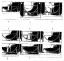
図1乃至図15等は、其々、本発明による容器の実施形態について示しており、いずれの場合にも、変形例を複数の図、全体図及び/又は部分図で、示している。 FIGS. 1 to 15 and the like show embodiments of the container according to the present invention, and in each case, a modification is shown in a plurality of views, an overall view and / or a partial view.
概して、本発明は、上部、中心部及び下部を有する、包装体として機能する圧力容器に関し、該容器の上部は、圧力容器が充填されることができる開口部を備え、弁又は閉塞体が組込まれることができ、包装体は、約20バールまで、更に100バールまで、又は特に温度約55°Cでは、更に300バールまでの範囲で加圧状態になる。 In general, the present invention relates to a pressure vessel that functions as a package having an upper portion, a center portion, and a lower portion, the upper portion of the vessel having an opening that can be filled with a pressure vessel and incorporating a valve or closure. The package can be under pressure in the range up to about 20 bar, even up to 100 bar, or even up to 300 bar, especially at a temperature of about 55 ° C.
基部は、容器下に配置される別の構成要素を形成する一方で、容器を加圧するために弁を備える。中心部は、例えば筒状又は角柱状の外形を有する。 The base comprises a valve to pressurize the container while forming another component located under the container. The central portion has, for example, a cylindrical or prismatic outer shape.
圧力容器は、接合部13を用いて容器1に取着されるベース2によって底部で密閉される。接合部13は、接着、巻締(seaming)又は溶着によって得ることができる。或いは、容器は、閉塞用カバーベース18によって閉塞される。また、容器1は、カバー5で閉塞され、該カバーは、投与弁17又はねじキャップ又は別の閉塞体としてもよい。
The pressure vessel is sealed at the bottom by a
このように、容器は、別々に嵌合されるベースを有することがある、又は本明細書では、一体として作製される可能性もある。 Thus, the container may have a base that is fitted separately, or may be made herein as one piece.
一次容器1は、長手方向軸lに沿って延在する略筒状体22、上部にある閉塞体5、及び分離の如何に関わらず、以下に提示するように様々な形状を取ることができる追加ベース21を含む。好適には、略筒状体22は、容器内に充填された製品の高さがユーザに視認可能に保てるように、特に透明な、プラスチックから作製される。これは、半透明、透き通った、又は単に透明な壁を含むと理解されるべきである。略筒状体22を形成するのに選択される特定の材料は、容器内に収容される充填製品に関して化学的に不活性でなければならない、且つ連続又は不連続充填製品を加圧包装するという使用目的に応じて、十分な強度及び耐久性も提供しなければならない。適当な材料の例を、以下に挙げる。
The
対応する容器製造方法と共に以下で詳述するように、筒状体又は角柱体は、射出成形技術を使用して、又は押出成形によって、作製されることができる。 As detailed below with the corresponding container manufacturing method, the cylindrical body or prismatic body can be made using injection molding techniques or by extrusion.
圧力容器壁22に十分な強度を与えるために、補強要素が、少なくとも圧力容器の壁22に設けられる。そうした補強要素としては、第1例の機械的補強要素30があり、該要素は、有利には、容器本体の壁22周りに配設される周縁補強要素の形で設けられる。筒状壁の場合は、円形リングとなり、該リングは、有利には、容器の長手方向軸lと直交して延伸する領域内に延伸し、それにより壁に対するリングの補強作用を最大限活用できる。
In order to give the
好適には、複数の補強リングが、容器壁に沿って設けられ、該補強リングは、特に奇数の場合、圧力容器の内側及び/又は外側其々で、互いに離間して配置され、真ん中にあるリングが、容器壁22の中間高さで、適切に嵌合されるようにするが、該中間高さは、確実に補強リングが互いに等距離で設けられた場合、基本的に容器の中で最も必要とされる領域である。
Preferably, a plurality of reinforcing rings are provided along the container wall, the reinforcing rings being arranged in the middle and spaced apart from one another, respectively inside and / or outside the pressure vessel, especially in the case of odd numbers The ring is properly fitted at the intermediate height of the
しかしながら、補強リングは、異なる長手方向配分に従い、特に本体上端部及び下端部から其々、中心部に向かい距離を減少させて、嵌合させることもでき、その結果、連続する補強リング間の中間領域は、本体の中央に向かい減少する。確かに、これにより、容器の中で強度が最も要求される部分、つまり中間部で強度を増強できる。 However, the reinforcing rings can also be fitted according to different longitudinal distributions, in particular from the upper and lower ends of the body, reducing the distance towards the central part, respectively, so that the intermediate between successive reinforcing rings The area decreases towards the center of the body. Certainly, this makes it possible to increase the strength in the most demanding portion of the container, that is, the intermediate portion.
補強要素31、32は、特に外向きの頂部を有する略準円形の断面図を持つ、丸みを帯びた外形にすると有利である。この外形パターンのために、局所的な張力が、最適に結合され、合わさって、容器壁に対して最大張力を印加でき、それにより外方に曲折又は隆起する可能性が高くなる傾向が、抑制される。
It is advantageous if the reinforcing
好適には、補強リングの幅は、図49に示された連続リング間の間隔の半分より狭く、好適には大幅に狭く、又はそれ以下に保ち、それにより容器壁の平均厚が、比較的小さい値となるようにする。 Preferably, the width of the reinforcing ring is less than half of the spacing between the continuous rings shown in FIG. 49, preferably much less or less, so that the average thickness of the container wall is relatively Try to make it smaller.
上記補強リングは、本質的に、外壁に設けられるが、内壁に嵌合されることもでき、場合によっては、例えば、少なくとも壁の弱い箇所で、確実に要求される壁の強度を得るために、外壁上の補強リングと組み合わせて設けることも可能である。 The reinforcing ring is essentially provided on the outer wall, but can also be fitted to the inner wall, and in some cases, for example, at least in weak areas of the wall to ensure the required wall strength. It can also be provided in combination with a reinforcing ring on the outer wall.
長手方向の又は径方向のリブといった他の種類のリブは、ここでは意図的に使用されない。内側から作用する圧力の影響で容器壁が変形するのを防ぐリブの効果は、いずれにせよかなり小さい。従って、長手方向軸lに直交する領域内に延伸する周縁補強リブ又はリングは、圧力が作用して容器壁を膨張し得る傾向を打ち消す際に、かなり効果的であり、圧力の作用は、上記他の種類の補強リブの場合よりも、僅かに又はかなり小さくなる。そのため、これらの補強要素は、高内圧に対して耐性を持たせるのに役立つ。また、補強要素は、容器周りにフィルムを巻装する及び/又はフィルムを収縮させることによって、容器に接合される内側支持リング群によっても、得られる。 Other types of ribs, such as longitudinal or radial ribs, are not intentionally used here. In any case, the effect of the ribs to prevent the container wall from being deformed by the influence of pressure acting from the inside is quite small. Thus, peripheral reinforcing ribs or rings extending in a region perpendicular to the longitudinal axis l are quite effective in counteracting the tendency for pressure to act and expand the vessel wall, the effect of pressure being Slightly or considerably smaller than with other types of reinforcing ribs. Therefore, these reinforcing elements help to withstand high internal pressures. The reinforcing element is also obtained by a group of inner support rings joined to the container by wrapping the film around the container and / or shrinking the film.
或いは、上記補強要素は、直接容器の材料に存在させる肥厚部群又は補強リブ群で;有利には容器のブロー工程中に直接嵌合させられる外側支持リング群で、網目及び/又は格子及び/又は格子が既に組込まれている収縮包装フィルムによって、構成してもよい。 Alternatively, the reinforcing element is a thickened group or reinforcing rib group which is present directly in the container material; preferably an outer support ring group which is fitted directly during the container blowing process, with a mesh and / or grid and / or Or you may comprise by the shrink-wrap film in which the grating | lattice is already integrated.
場合によっては、上記外側支持リングは、金属製とすることもでき、上記外側又は内側支持リングは、プラスチック製としてもよい。 In some cases, the outer support ring may be made of metal, and the outer or inner support ring may be made of plastic.
好適には、補強手段は、内容体を挿入して、次に該内容体が接合部でベースに取着されることによって、実装され、この内容体を内圧状態にすることで、一次容器によって更に支持され、場合によっては接合部なしに、接着又は溶着によって該一次容器に接合される。リングは、接着又は溶着によって取着されることもできる。 Preferably, the reinforcing means is implemented by inserting the content body and then attaching the content body to the base at the joint and bringing the content body into an internal pressure state, thereby allowing the primary container to Further supported and optionally joined to the primary container by bonding or welding without a joint. The ring can also be attached by gluing or welding.
試験し易い実施例は、例えば、6バールで容器内を加圧し、変形を測定し、上部に沿って2.5バールを加え、再び変形を測定することから成る。そうすると、上記容器は、6バールに耐え得る必要があるが、上記容器が、2.5バールの加圧状態である場合、この2.5バールの圧力は、内容体で反対方向に作用すると考えられ、その結果、内容体が耐えねばならない圧力、又は実際に容器の壁が感じる圧力は、実際は3.5バール、即ち6−2.5バールとなる。主な用途は、内容体を軽量化することである。確かに、該容器の壁は、3.5バールだけに耐えるだけでよくなるため、内容体は6バールに耐える必要はなく、その結果壁が薄くされてもよくなる。従って、二重容器の更なる利点は、パスカルの原理を適用して得られ、これに関連する両容体の片方が、低圧に耐えられればよいという効果が得られ、これは、特定用途でかなり有用となるかも知れない。そのために、上記内容体には、基本的に、あまり機械的な応力が加えられない。その結果、この容器を更に軽量化できる。これは、重要な利点である、即ち、容器内で発生される逆圧のために一層軽量な容器が作製されることができる。この実施例では、内容体は、圧力容器として機能し、加圧状態の内容体が、該内容体を囲む外容体を実際に保護し、それにより実際に、相補的容器として機能する。そのため、上記内容体は、減圧してベース容器に負圧を加える、即ち、上記二重容器システムにおいて、片方の容体には、もう片方の容体が作用して、低圧が加わる。ボトル容器の場合、ボトル中のボトルが、1チャンバとなり、内側ボトルが、外側ボトルの更なる補強手段として機能する。従って、内容体は、圧力調整器を介して加圧され、それによって異なる2圧力が、圧力勾配DPを生成して、制御されるが、該圧力勾配DPは、内容体とベース容器との差であり、特定の圧力差、DPを有する。このDPによって、上記内容体は、軽量化されることができる。これは、このパスカルの原理を適用したものである。 An easy-to-test example consists, for example, of pressurizing the container at 6 bar, measuring the deformation, adding 2.5 bar along the top and measuring the deformation again. Then the container needs to be able to withstand 6 bar, but if the container is under pressure of 2.5 bar, this 2.5 bar pressure will act in the opposite direction on the contents. As a result, the pressure that the contents must withstand, or the pressure that the container wall actually feels, is actually 3.5 bar, ie 6-2.5 bar. The main use is to reduce the weight of the contents. Indeed, since the container wall need only withstand 3.5 bar, the contents need not withstand 6 bar, so that the wall may be thinned. Thus, a further advantage of the double container is obtained by applying Pascal's principle, with the effect that one of the two associated volumes only has to withstand low pressures, which is quite significant in certain applications. May be useful. Therefore, mechanical stress is not applied to the contents body basically. As a result, this container can be further reduced in weight. This is an important advantage, i.e. a lighter container can be made due to the counter pressure generated in the container. In this embodiment, the contents function as a pressure vessel, and the pressurized contents actually protect the outer body surrounding the contents, thereby actually functioning as a complementary container. For this reason, the content is decompressed and negative pressure is applied to the base container. That is, in the double container system, the other container acts on one container and a low pressure is applied. In the case of a bottle container, the bottle in the bottle becomes one chamber, and the inner bottle functions as a further reinforcing means for the outer bottle. Thus, the contents are pressurized via a pressure regulator, whereby two different pressures are controlled, producing a pressure gradient DP, which is the difference between the contents and the base container. And has a specific pressure difference, DP. The content body can be reduced in weight by this DP. This is an application of this Pascal principle.
上述した機械的補強要素の他に、場合によっては、化学的補強手段も、後述するように使用されてもよい。容器壁に対して補強作用を累積させ、それにより作用圧力に関する剛性を大幅に高めるために、上記化学的補強要素は、場合によっては、上記機械的補強要素と組み合わせて使用され、その結果、容器に作用する圧力に関わらず、容器壁を完璧に補強可能にしてもよい。 In addition to the mechanical reinforcement elements described above, in some cases chemical reinforcement means may also be used as described below. In order to accumulate the reinforcing action on the container wall and thereby greatly increase the stiffness with respect to the working pressure, the chemical reinforcing element is sometimes used in combination with the mechanical reinforcing element, so that the container Regardless of the pressure acting on the container wall, the container wall may be perfectly reinforced.
目的は、とりわけ気体、充填製品を入れた包装体を、約20バールに、それより高く100バール以上に、又は特に約55°Cで、300バールにまで昇圧させて、少なくとも加圧包装するが、この加圧包装は、とりわけ、軟質プラスチック製の細管であるシール4を用いて自閉可能な開口部3を介して、閉塞可能な上側弁17及び/又は閉塞可能な下側弁を介して、行われ、及び/又は、上記自閉可能な「傘プラグ(umbrella plug)」6を介して、又は上記二段階の「ニコルソンプラグ(Nicholson plug)」7を介して行われるが、両プラグは、市販部品である。
The purpose is to pack, at least under pressure, a package containing, inter alia, gas, a filled product, to a pressure of about 20 bar, higher than 100 bar, or in particular at about 55 ° C. up to 300 bar. The pressure packaging is, in particular, via the
容器1若しくは1’が高内圧に対する耐性を持つために、本発明は、様々な方法で該容器を補強することにある。例えば、互いに離間して配置され、例えば、接着又は溶着によって容器に接合される内側支持リング8及び8’を用いて補強する。8と8’との間の距離、及び配置される支持リングの数は、要求される容器の強度に応じて決まる。及び/又は、容器1の材料内に直接存在させる肥厚部又は補強リブ9及び9’によって補強する。9と9’との間の距離及び配置される支持リングの数は、要求される容器の強度に応じて決まる。及び/又は、互いに離間して配置され、接着若しくは溶着によって、又は単に接合部なしに接合される外側支持リング10及び10’によって補強する。10と10’との間の距離及び配置される支持リングの量は、要求される容器の強度に応じて決まる。これらの外側支持リング10は、容器のブロー工程中に直接嵌合されることが可能である。本発明は、これらの外側支持リングに限定されない−図示したのみ−が、網目又は格子としてもよい。これらの支持リングの材料は、金属とプラスチックの両方としてもよい。及び/又は、接合部でベース2に取着される内容体14を挿入することで容器を補強する。接合部12は、例えば、接着、巻締又は溶着によって得てもよい。その後、この内容体14は内圧状態で、容器1によって更に支持される。
In order for the
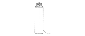
容器包装体23は、1つの開口端部を有する、即ち、下部を切断していない。また、容器包装体は、例えば改質PET等のプラスチックから成り、それにより高圧及び/又は高温に耐性を有する点で注目に値する。ベースの下部は、略偏平に、場合によっては内側に向かい僅かに湾曲して設計される。
The
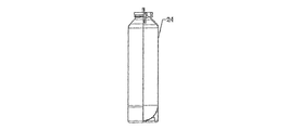
1つの開口端部を有する、即ち、下部で切断していない容器包装体24は、例えば改質PET等のプラスチック材料から成り、それにより高圧に耐性を有する点で注目に値する。ベースの下部は、ここでは、半球に設計されているが、これは、この形状が、容器内の高圧に耐えられるためである。この実施形態では、ベースカップ25が必要で、該ベースカップ25は、包装体を、立ち向き姿勢のために直立に保持可能にし、容器に、特に容器底面で、より詳細には、底部21と本体22との間の移行領域の高さで、取着される。ベースカップ25は、接着又は溶着によって容器に取着される。
The
容器包装体24の形状は、必ずしも筒状とするわけではなく、他の形状、例えば角柱、特に丸みを帯びた角部を有する三角形とすることもできる。
The shape of the
容器包装体26は、3段階の工程により製造される点で、注目に値する。まず、プリフォーム射出成形を行い、次にプリフォームを膨張によってブロー成形して、ボトルを形成し、その後ボトルを切断する。容器は、該容器に接着又は溶着によって取着されるフルカバー28によって下部で閉塞される。
The
容器包装体29は、PET材料から作製され、内容体30は、上記切断によって作成された外容体29の下にある開口部を通して挿入される。内容体30は、必ずしも外容体29と同じ材料から作製されなくてもよく、必ずしも円筒形としなくてもよい。外容体29の下側開口部は、カバー又はベースカップ25’を介して閉塞され、該ベースカップ25’は、接着又は溶着によって容器に取着される。内容体30は、上から弁5’で閉塞される。内容体30の壁は、外容体によって高内圧で支持され、その結果、こうした容器包装体は、高圧、例えば最高20バールに対して、耐性が高くなる。
The
容器包装体29’は、外容体29の変形例であり、弁5’が、容器包装体に組込まれており、そのため移動可能でなくなり、外部から離隔され、更なる安全対策として、外容体29’の内壁を通して弁を保持している。
The container package 29 'is a modified example of the
容器包装体29”は、外容体29の更なる変形例であり、外容体が2回、すなわち、上下で、切断されている点で、注目に値する。
The
容器包装体30は、1つの開口端部を有する、即ち、下部で切断しておらず、特に改質PETといったプラスチックから成り、それにより高圧に耐性を有する点で注目に値する。
The
大気包装及び/又は加圧包装の場合、容器は、閉塞用カバーベース18で閉塞されることができ、上記方法により、加圧又は非加圧されることができる。これは、1チャンバシステムと呼ばれる。
In the case of atmospheric packaging and / or pressurized packaging, the container can be closed with the
図22は、2チャンバシステムを示しており、容器は、上記の様々な方法により、下部で閉塞され、2チャンバは、容器内でチャンバ区画体19を嵌合させることによって、得られる。チャンバ区画体19は、圧力制御弁20を備えても、又は備えなくてもよいが、この圧力制御弁20は、例えば、外部から開けられる閉塞体としてもよく、それにより、チャンバ21の内容物が、チャンバ22と接触するようにしてもよい。チャンバは、加圧状態でも、又は非加圧状態でもよい。
FIG. 22 shows a two-chamber system where the container is closed at the bottom and the two chambers are obtained by fitting the
上記本発明による3チャンバシステム又はマルチチャンバシステム(図示せず)では、1つ又は複数のチャンバ区画体19及び19’が嵌合される。チャンバ区画体19’が嵌合されるだけで、第3チャンバ23が、得られる。チャンバ区画体は、圧力制御弁20、又は例えば、チャンバ21の内容物がチャンバ22と接触するように外部から開けられる閉塞体を備えられる。チャンバは、加圧状態でも、又は非加圧状態でもよい。
In the above three-chamber system or multi-chamber system (not shown) according to the present invention, one or more chamber compartments 19 and 19 'are fitted. The
多数のチャンバは、異なるチャンバ区画体を嵌合することによって、作成されることができる。異なるチャンバで、充填製品は、液体、粉体又は気体で構成してもよい。チャンバは、加圧状態でも、又は非加圧状態でもよい。従って、圧力包装体は、少なくとも2チャンバから成るマルチチャンバシステムによって形成されることができ、2チャンバシステムの場合、容器の下部は、特定したように閉塞され、チャンバ区画体は、容器内に異なるチャンバを作成するために、嵌合される。この場合、チャンバ区画体は、少なくとも1つの圧力制御弁又はガス抜き弁(gassing valve)を備えられる。特に、この圧力制御弁は、該圧力制御弁を用いて外側から間接的に開けられる閉塞体としてもよく、それにより1チャンバの内容物が、他のチャンバと接触できるようにし、チャンバは、加圧されても、又は加圧されなくてもよく、場合によっては、基部側及び上側の両方が、同一の閉塞用片体、即ち閉塞体を用いて閉塞され、特に、このカバーは、投与弁、又は場合によっては、ねじキャップ若しくは他の閉塞体から成る。 Multiple chambers can be created by fitting different chamber compartments. In different chambers, the filled product may consist of liquid, powder or gas. The chamber may be pressurized or unpressurized. Thus, the pressure package can be formed by a multi-chamber system consisting of at least two chambers, in which case the lower part of the container is closed as specified and the chamber compartments are different within the container. Fit to create a chamber. In this case, the chamber compartment is provided with at least one pressure control valve or gassing valve. In particular, the pressure control valve may be a closure that can be opened indirectly from the outside using the pressure control valve, thereby allowing the contents of one chamber to contact another chamber, It may or may not be pressurized, and in some cases both the base side and the upper side are occluded with the same occlusion piece, i.e. the occlusion body, in particular this cover is a dosing valve Or, in some cases, a screw cap or other closure.
また、本発明は、一段階若しくは二段階工程1によって形成される、プラスチック製、例えばPET製の容器から成る、又は管を得るために、一段階若しくは二段階工程後に、容器を切断することによって形成される容器から成る圧力包装マルチチャンバシステムにも関する。或いは、容器Vは、押出し法によっても形成される。
The invention also consists of a container made of plastic, for example PET, formed by a one-step or two-
容器は、接合部13を用いて容器1に取着されるベース2によって下部で閉塞される。接合部13は、例えば、接着、巻締又は溶着によって得られる。或いは、これは、閉塞用カバーベース18によって下部で閉塞される。
The container is closed at the bottom by a
上部で、容器1は、カバー5で上から閉塞され、このカバーは、投与弁17、ねじキャップ又は他の閉塞体としてもよい。
At the top, the
容器1が、押出し法によって作製される場合、上側は、接合部12を用いて容器1に取着される容器ヘッド11で閉塞される。接合部12は、例えば、接着、巻締又は溶着によって得られる。
When the
次に、容器ヘッド11は、カバー5で閉塞されることができ、該カバーは、投与弁17又はねじキャップ又は他の閉塞体としてもよい。
The
液体、ペースト、クリーム等の充填製品が、外壁と、また圧力ガス(気体、空気等)と接触するのを防ぐために、軟質内容体16は、例えばブローによって、容器内に挿入される。
In order to prevent filling products such as liquids, pastes, creams, etc. from coming into contact with the outer wall and with pressure gases (gas, air, etc.), the
また、本発明は、容器包装体、特に、上記で定義されたような圧力容器包装体を製造する方法にも関し、本明細書で使用される容器は、一段階工程の後に、管を得るために容器を切断して形成され、本明細書では、圧力手段は、ガス抜きによって、特に大気圧から約100バールに、充填製品を入れた容器包装体を加圧するように配設される。 The present invention also relates to a method for producing a container package, in particular a pressure container package as defined above, wherein the container used herein obtains a tube after a one-step process. For this purpose, it is formed by cutting the container, in which the pressure means are arranged to depressurize the container package containing the filled product, particularly from atmospheric pressure to about 100 bar, by venting.
また、容器は、一段階工程の代わりに二段階工程によって形成されてもよく、本明細書で使用される容器は、射出成形によって、切断されることなく直接形成されることができる。 Also, the container may be formed by a two-step process instead of a one-step process, and the container used herein can be directly formed without being cut by injection molding.
本明細書での加圧は、シールを用いて自閉可能な開口部を介して、閉塞可能な下側の弁を通じて行われることができ、このシールは、軟質プラスチック製の管要素から成り、特に、本明細書での加圧は、閉塞可能な上側の弁を介して行う。 The pressurization herein can be performed through a lower valve that can be closed through an opening that is self-closable using a seal, which consists of a tube element made of soft plastic, In particular, the pressurization herein is performed via an upper valve that can be closed.
圧力包装体を製造する特定の方法によると、圧力包装体は、押出し法によって形成された容器を用いて、又は少なくとも1回、特に2回切断される押出成形された管を用いて形成され、その結果得られた本体の両開口端部は、同一の片体、閉塞体又はカバーによって閉塞される;特に、上縁部は、接合部を用いて容器に取着される容器ヘッドで閉塞され、より詳細には、容器ヘッドは、次に、カバーによって閉塞され、このカバーは、投与弁、又はねじキャップ又は他の閉塞体である。 According to a particular method of producing a pressure package, the pressure package is formed using a container formed by an extrusion method or using an extruded tube that is cut at least once, especially twice, The resulting open ends of the body are closed by the same piece, closure or cover; in particular, the upper edge is closed by a container head attached to the container using a joint. More particularly, the container head is then closed by a cover, which is a dosing valve, or a screw cap or other closure.
纏めると、本発明の圧力容器1に組込まれる主要な点は、物理的補強手段、特に金属ホイル、補強リング及び/又はリブ、内部及び/又は外部スロット、及び/又は、特に、結晶化度、ガラス転移温度を高めること、PENの使用を含む、結晶化度を高めるポリマーを混合することによる化学的補強手段、及び/又は、特に、混合、内部コーティングを含むコーティングを用いた、耐化学性、及び/又は、特に、補強手段として「ボトル内ボトル」タイプ、「ボトル内バッグ」、1チャンバ又は2チャンバシステム、又は「ベースカップを有する球体基部」といった特別な構造タイプの圧力容器である。
In summary, the main points incorporated into the
Claims (66)
方法。 The pressure vessel is formed using an extruded tube (3) that is cut at least once, in particular twice, so that both open ends of the body (22 ′) thus formed are 45. Method according to claim 44, for producing a pressure vessel, in particular as defined in one of claims 1 to 43, sealed by a piece, valve or cover (5).
Method.
第1ステップ(A)で、プリフォームが、射出成形によって半製品として押出されるが、射出成形では、プラスチック粒状物が乾燥され、押出機で溶融され、次に射出金型に押込まれるステップ、
次のステップ(B)で、前記半製品が、ブロー金型にブローされて、更なる中間製品(3)として、ボトル形状、特に管(3)状にされるステップ、
更なる次のステップ(C)で、前記更なる中間製品(3)の下部が、特定の長さで切断され、その後、別に加えられる射出成形ベース(21)が、前記更なる中間製品(3)に組込まれるステップによって実行されることを特徴とする、請求項44乃至51の何れか一項に記載の方法。 It is a method of manufacturing the pressure vessel package according to any one of claims 1 to 43, and the manufacturing process of the pressure vessel includes the following steps:
In the first step (A), the preform is extruded as a semi-finished product by injection molding, in which the plastic granules are dried, melted in an extruder, and then pressed into an injection mold. ,
In the next step (B), the semi-finished product is blown into a blow mold to form a further intermediate product (3) into a bottle shape, in particular a tube (3),
In a further next step (C), the lower part of the further intermediate product (3) is cut to a specific length and then added separately, an injection molding base (21) is added to the further intermediate product (3). 52. The method according to any one of claims 44 to 51, wherein the method is carried out by the steps incorporated in.
Applications Claiming Priority (5)
| Application Number | Priority Date | Filing Date | Title |
|---|---|---|---|
| BE2011/0705 | 2011-12-05 | ||
| BE201100705A BE1020615A5 (en) | 2011-12-05 | 2011-12-05 | CONTAINER PACKAGING FOR PACKAGING PRESSURE OF FILLED GOODS I.H.B. HALF LIQUID, AND METHOD FOR THIS. |
| BE2012/0681 | 2012-10-10 | ||
| BE2012/0681A BE1025052B1 (en) | 2012-10-10 | 2012-10-10 | CONTAINER FOR PACKAGING UNDER PRESSURE OF CONTINUOUS FILL PRODUCT, AND PRODUCTION METHOD FOR THIS |
| PCT/BE2012/000053 WO2013082680A2 (en) | 2011-12-05 | 2012-12-05 | Plastic container for packing of filling product under pressure, and method for the manufacture thereof |
Related Child Applications (1)
| Application Number | Title | Priority Date | Filing Date |
|---|---|---|---|
| JP2017207754A Division JP2018030647A (en) | 2011-12-05 | 2017-10-27 | Method of manufacturing plastic container for packing of filling product under pressure |
Publications (2)
| Publication Number | Publication Date |
|---|---|
| JP2015500778A true JP2015500778A (en) | 2015-01-08 |
| JP2015500778A5 JP2015500778A5 (en) | 2016-02-04 |
Family
ID=48463648
Family Applications (2)
| Application Number | Title | Priority Date | Filing Date |
|---|---|---|---|
| JP2014545048A Pending JP2015500778A (en) | 2011-12-05 | 2012-12-05 | Plastic container for pressure-packing filled products and method of manufacturing the same |
| JP2017207754A Pending JP2018030647A (en) | 2011-12-05 | 2017-10-27 | Method of manufacturing plastic container for packing of filling product under pressure |
Family Applications After (1)
| Application Number | Title | Priority Date | Filing Date |
|---|---|---|---|
| JP2017207754A Pending JP2018030647A (en) | 2011-12-05 | 2017-10-27 | Method of manufacturing plastic container for packing of filling product under pressure |
Country Status (28)
| Country | Link |
|---|---|
| US (1) | US20150076164A1 (en) |
| EP (2) | EP3095731B1 (en) |
| JP (2) | JP2015500778A (en) |
| KR (1) | KR20140100991A (en) |
| AP (1) | AP3924A (en) |
| AU (1) | AU2012350168A1 (en) |
| BE (2) | BE1025871B1 (en) |
| BR (1) | BR112014013437A2 (en) |
| CA (1) | CA2854929C (en) |
| CY (1) | CY1118673T1 (en) |
| DK (2) | DK2791030T3 (en) |
| EA (1) | EA030100B1 (en) |
| ES (2) | ES2918973T3 (en) |
| HR (1) | HRP20161034T1 (en) |
| HU (2) | HUE059222T2 (en) |
| IL (1) | IL232962A0 (en) |
| LT (1) | LT2791030T (en) |
| ME (1) | ME02494B (en) |
| MX (1) | MX2014006524A (en) |
| PH (1) | PH12014501552A1 (en) |
| PL (2) | PL2791030T3 (en) |
| PT (2) | PT3095731T (en) |
| RS (1) | RS55197B1 (en) |
| SG (1) | SG11201402946XA (en) |
| SI (1) | SI2791030T1 (en) |
| SM (1) | SMT201600414B (en) |
| WO (1) | WO2013082680A2 (en) |
| ZA (1) | ZA201403371B (en) |
Families Citing this family (16)
| Publication number | Priority date | Publication date | Assignee | Title |
|---|---|---|---|---|
| CN104955742B (en) | 2012-11-28 | 2017-05-03 | 爱柔包装技术集团有限公司 | System and method for manufacturing pressure units |
| FR3008078B1 (en) * | 2013-07-08 | 2016-04-01 | Lablabo | DEVICE WITH RIGID CONTAINER AND FLEXIBLE CYLINDRICAL POCKET FOR PACKAGING FLUIDS. |
| FR3019803B1 (en) * | 2014-04-10 | 2016-12-23 | Fareva | AEROSOL GENERATOR OF PLASTIC MATERIAL |
| KR102153024B1 (en) * | 2014-09-03 | 2020-09-07 | 현대자동차주식회사 | Pressure vessel for cng and manufacturing method thereof |
| BE1022703B1 (en) * | 2015-02-10 | 2016-08-17 | CARDIFF GROUP,naamloze vennootschap | Barrel for CO2-containing drinks and their use |
| WO2017080685A1 (en) * | 2015-11-10 | 2017-05-18 | Gojara | Pressure control device, dispenser comprising said pressure control device and method of manufacturing |
| USD833885S1 (en) * | 2017-01-10 | 2018-11-20 | Karen Montileone | Container with detachable bottom and dispenser |
| BE1024253B1 (en) | 2017-04-03 | 2018-01-05 | Gojara Bvba | DISC PRESSURE CONTROL DEVICE FOR PRESSURE PACKAGING |
| US11851264B2 (en) * | 2017-04-03 | 2023-12-26 | Gojara Bvba | Disc-shaped pressure control device for pressure packaging |
| US20200171734A1 (en) * | 2017-08-11 | 2020-06-04 | Husky Injection Molding Systems Ltd. | Molded article, container and a method for printing thereon |
| BE1025483B1 (en) | 2018-02-12 | 2019-03-14 | Resilux N.V. | PRESSURE PACKAGING WITH IMPROVED FALL RESISTANCE AND BUMP RESISTANCE |
| CH715159A1 (en) * | 2018-07-09 | 2020-01-15 | Alpla Werke Alwin Lehner Gmbh & Co Kg | Plastic pressure vessel with a valve attachment for dispensing a gaseous, liquid, powdery or pasty filling material. |
| US10486892B1 (en) * | 2018-08-22 | 2019-11-26 | The Procter & Gamble Company | Packages and arrays of packages for plastic aerosol dispensers |
| KR102404250B1 (en) * | 2020-06-30 | 2022-06-02 | 주식회사 신광엠앤피 | Spray container with pressurized filling dispenser |
| CN113507803B (en) * | 2021-06-15 | 2022-03-01 | 杭州电子科技大学 | Preparation method of deep-sea pressure-resistant container with imitated siderite beetle bionic structure |
| BE1030302B1 (en) | 2022-02-25 | 2023-09-25 | Gojara Bv | 2K PLASTIC BASE FOR A SPRAY CAN WITH INTEGRATED AERATION PLUG |
Citations (14)
| Publication number | Priority date | Publication date | Assignee | Title |
|---|---|---|---|---|
| JPS542214U (en) * | 1977-06-08 | 1979-01-09 | ||
| JPH0195261U (en) * | 1987-12-18 | 1989-06-23 | ||
| JPH02214555A (en) * | 1989-02-14 | 1990-08-27 | Toyo Seikan Kaisha Ltd | Aerosol packing vessel made of plastic |
| JPH06144434A (en) * | 1992-11-02 | 1994-05-24 | Akio Maru | Reinforcing method for soft container made of paper, plastic or the like |
| JP2001200994A (en) * | 2000-01-19 | 2001-07-27 | Brunswick Corp | Camp type container for liquefied gas fuel |
| US20020005044A1 (en) * | 1998-03-31 | 2002-01-17 | Mahajan Gautam K. | Double walled bottle |
| JP2003040368A (en) * | 2001-07-31 | 2003-02-13 | Daizo:Kk | Discharger for a plurality of content substances |
| US20030178432A1 (en) * | 2002-03-25 | 2003-09-25 | Meiland Nico J. | Pressure container |
| JP2005059865A (en) * | 2003-08-08 | 2005-03-10 | Yoshino Kogyosho Co Ltd | Double container and molding method for the same |
| JP2008162666A (en) * | 2006-12-28 | 2008-07-17 | Yoshino Kogyosho Co Ltd | Discharging container |
| JP2009514747A (en) * | 2005-11-03 | 2009-04-09 | サザン スター コーポレイション | Plastic aerosol container with improved annular collar |
| JP2010222019A (en) * | 2009-03-23 | 2010-10-07 | Daizo:Kk | Lid body, pressure reducing structure inside container, and spray container |
| JP2011136747A (en) * | 2009-12-29 | 2011-07-14 | Daizo:Kk | Inner bag and double aerosol product using the same |
| JP2011251710A (en) * | 2010-05-31 | 2011-12-15 | Daizo:Kk | Manufacturing method of multilayer bottle product, and multilayer bottle product manufactured by the same method |
Family Cites Families (18)
| Publication number | Priority date | Publication date | Assignee | Title |
|---|---|---|---|---|
| US2766072A (en) * | 1952-08-02 | 1956-10-09 | Standard Container Inc | Aerosol sprayer with a replaceable cartridge |
| BE538645A (en) * | 1954-06-09 | |||
| US3327907A (en) | 1965-06-09 | 1967-06-27 | Meyers Frederick Charles | Reinforced plastic containers for pressurized products |
| US3837527A (en) * | 1973-03-16 | 1974-09-24 | L Kutik | Reinforced aerosol container |
| US4039103A (en) * | 1974-12-18 | 1977-08-02 | Hubert Juillet | Pressurized dispensing containers |
| US4122142A (en) | 1977-08-05 | 1978-10-24 | Owens-Illinois, Inc. | Method for blow molding a reinforced plastic bottle |
| SE417592B (en) | 1978-03-13 | 1981-03-30 | Plm Ab | CONTAINER OF THERMO-PLASTIC PLASTIC MATERIAL WITH STRENGTHS INSIDE THE CONTAINER WALL, AND PROCEDURE FOR THE PREPARATION OF SUCH A CONTAINER |
| CA2013636A1 (en) | 1989-04-06 | 1990-10-06 | Sang I. Han | Disposable pressure wound irrigation device |
| US4988399A (en) * | 1989-07-05 | 1991-01-29 | Aluminum Company Of America | Process for making a three-piece container involving stretch-blow molding, severing and attaching an end panel to the open bottom |
| EP0778225B1 (en) | 1995-11-13 | 1998-07-08 | L'oreal | Aerosol container |
| US5865350A (en) | 1997-01-24 | 1999-02-02 | Pure Vision International L.L.P. | Spray bottle with built-in pump |
| US20020166837A1 (en) | 2001-05-09 | 2002-11-14 | Gonzalez Frank C. | Container side wall with ribs causing a predefined varying thickness |
| NL1022456C2 (en) * | 2003-01-21 | 2004-07-22 | Packaging Tech Holding Sa | Pressure package system for applying a working pressure to a fluid contained in a pressure package. |
| FR2852301B1 (en) | 2003-03-13 | 2006-02-10 | Valois Sas | DEVICE FOR DISPENSING FLUID PRODUCT |
| WO2005071306A1 (en) * | 2004-01-23 | 2005-08-04 | Sergei Glebovich Koldybaev | Container with transparent liner and semitransparent wall |
| EP1725476B1 (en) | 2004-01-30 | 2007-10-31 | Intelligent Packaging Systems Group S.A. | Pressure control device |
| US20070045221A1 (en) | 2005-08-26 | 2007-03-01 | Graham Packaging Company, L.P. | Plastic container having a ring-shaped reinforcement and method of making same |
| DE102006004120A1 (en) * | 2006-01-25 | 2007-07-26 | Hydac Technology Gmbh | Hydraulic accumulator, has coaxially abutting plastics casings, with poppet valve for controlling supply and extraction of medium |
-
2012
- 2012-12-05 SI SI201230686A patent/SI2791030T1/en unknown
- 2012-12-05 DK DK12850745.6T patent/DK2791030T3/en active
- 2012-12-05 DK DK16001088.0T patent/DK3095731T3/en active
- 2012-12-05 EP EP16001088.0A patent/EP3095731B1/en active Active
- 2012-12-05 CA CA2854929A patent/CA2854929C/en active Active
- 2012-12-05 AU AU2012350168A patent/AU2012350168A1/en not_active Abandoned
- 2012-12-05 ME MEP-2016-165A patent/ME02494B/en unknown
- 2012-12-05 PT PT160010880T patent/PT3095731T/en unknown
- 2012-12-05 MX MX2014006524A patent/MX2014006524A/en unknown
- 2012-12-05 BE BE2012/0826A patent/BE1025871B1/en active IP Right Grant
- 2012-12-05 JP JP2014545048A patent/JP2015500778A/en active Pending
- 2012-12-05 HU HUE16001088A patent/HUE059222T2/en unknown
- 2012-12-05 AP AP2014007757A patent/AP3924A/en active
- 2012-12-05 EA EA201491053A patent/EA030100B1/en not_active IP Right Cessation
- 2012-12-05 US US14/362,840 patent/US20150076164A1/en not_active Abandoned
- 2012-12-05 PL PL12850745T patent/PL2791030T3/en unknown
- 2012-12-05 EP EP12850745.6A patent/EP2791030B1/en active Active
- 2012-12-05 RS RS20160669A patent/RS55197B1/en unknown
- 2012-12-05 HU HUE12850745A patent/HUE029491T2/en unknown
- 2012-12-05 SG SG11201402946XA patent/SG11201402946XA/en unknown
- 2012-12-05 ES ES16001088T patent/ES2918973T3/en active Active
- 2012-12-05 BR BR112014013437A patent/BR112014013437A2/en not_active Application Discontinuation
- 2012-12-05 LT LTEP12850745.6T patent/LT2791030T/en unknown
- 2012-12-05 PT PT128507456T patent/PT2791030T/en unknown
- 2012-12-05 ES ES12850745.6T patent/ES2585413T3/en active Active
- 2012-12-05 PL PL16001088.0T patent/PL3095731T3/en unknown
- 2012-12-05 WO PCT/BE2012/000053 patent/WO2013082680A2/en active Application Filing
- 2012-12-05 KR KR1020147018854A patent/KR20140100991A/en not_active Application Discontinuation
-
2014
- 2014-05-12 ZA ZA2014/03371A patent/ZA201403371B/en unknown
- 2014-06-05 IL IL232962A patent/IL232962A0/en unknown
- 2014-07-04 PH PH12014501552A patent/PH12014501552A1/en unknown
-
2016
- 2016-08-10 CY CY20161100792T patent/CY1118673T1/en unknown
- 2016-08-17 HR HRP20161034TT patent/HRP20161034T1/en unknown
- 2016-11-15 SM SM201600414T patent/SMT201600414B/en unknown
-
2017
- 2017-10-27 JP JP2017207754A patent/JP2018030647A/en active Pending
- 2017-12-08 BE BE2017/5917A patent/BE1024913B1/en active IP Right Grant
Patent Citations (14)
| Publication number | Priority date | Publication date | Assignee | Title |
|---|---|---|---|---|
| JPS542214U (en) * | 1977-06-08 | 1979-01-09 | ||
| JPH0195261U (en) * | 1987-12-18 | 1989-06-23 | ||
| JPH02214555A (en) * | 1989-02-14 | 1990-08-27 | Toyo Seikan Kaisha Ltd | Aerosol packing vessel made of plastic |
| JPH06144434A (en) * | 1992-11-02 | 1994-05-24 | Akio Maru | Reinforcing method for soft container made of paper, plastic or the like |
| US20020005044A1 (en) * | 1998-03-31 | 2002-01-17 | Mahajan Gautam K. | Double walled bottle |
| JP2001200994A (en) * | 2000-01-19 | 2001-07-27 | Brunswick Corp | Camp type container for liquefied gas fuel |
| JP2003040368A (en) * | 2001-07-31 | 2003-02-13 | Daizo:Kk | Discharger for a plurality of content substances |
| US20030178432A1 (en) * | 2002-03-25 | 2003-09-25 | Meiland Nico J. | Pressure container |
| JP2005059865A (en) * | 2003-08-08 | 2005-03-10 | Yoshino Kogyosho Co Ltd | Double container and molding method for the same |
| JP2009514747A (en) * | 2005-11-03 | 2009-04-09 | サザン スター コーポレイション | Plastic aerosol container with improved annular collar |
| JP2008162666A (en) * | 2006-12-28 | 2008-07-17 | Yoshino Kogyosho Co Ltd | Discharging container |
| JP2010222019A (en) * | 2009-03-23 | 2010-10-07 | Daizo:Kk | Lid body, pressure reducing structure inside container, and spray container |
| JP2011136747A (en) * | 2009-12-29 | 2011-07-14 | Daizo:Kk | Inner bag and double aerosol product using the same |
| JP2011251710A (en) * | 2010-05-31 | 2011-12-15 | Daizo:Kk | Manufacturing method of multilayer bottle product, and multilayer bottle product manufactured by the same method |
Also Published As
Similar Documents
| Publication | Publication Date | Title |
|---|---|---|
| JP2015500778A (en) | Plastic container for pressure-packing filled products and method of manufacturing the same | |
| JP2015500778A5 (en) | ||
| US4014724A (en) | Bottle-shaped containers of the one-way type and a method for the manufacture of the same | |
| TW573106B (en) | Improved pressure container | |
| JP5491514B2 (en) | Container | |
| CN105593130B (en) | The constriction container of blowing | |
| CA2531562A1 (en) | Base design for pasteurization | |
| WO2010135843A1 (en) | Polyfoil tube made from semi-rigid or rigid foil materials | |
| MX2013009222A (en) | Vacuum panel with balanced vacuum and pressure response. | |
| JP6587830B2 (en) | Stretch blow double container and manufacturing method thereof | |
| JP5964039B2 (en) | Heat-resistant laminated blow molded container made of synthetic resin | |
| EP0126575A2 (en) | Friction-welded barriered containers | |
| JP7242174B2 (en) | Synthetic resin container, preform, and synthetic resin container manufacturing method | |
| JP5507188B2 (en) | Container | |
| JP2019214417A (en) | Container body and aerosol container | |
| GB2132935A (en) | Method for manufacturing containers | |
| JP2007045451A (en) | Self-standing bag | |
| JP7462379B2 (en) | Plastic Bottles | |
| JP7446051B2 (en) | plastic bottle | |
| JP2016069032A (en) | Pouch container and method of producing the same | |
| UA112666C2 (en) | PLASTIC CONTAINER FOR PACKING OF FILLER PRODUCT UNDER PRESSURE AND METHOD OF ITS MANUFACTURING |
Legal Events
| Date | Code | Title | Description |
|---|---|---|---|
| A521 | Request for written amendment filed |
Free format text: JAPANESE INTERMEDIATE CODE: A523 Effective date: 20141021 |
|
| A521 | Request for written amendment filed |
Free format text: JAPANESE INTERMEDIATE CODE: A523 Effective date: 20151207 |
|
| A621 | Written request for application examination |
Free format text: JAPANESE INTERMEDIATE CODE: A621 Effective date: 20151207 |
|
| A977 | Report on retrieval |
Free format text: JAPANESE INTERMEDIATE CODE: A971007 Effective date: 20160722 |
|
| A131 | Notification of reasons for refusal |
Free format text: JAPANESE INTERMEDIATE CODE: A131 Effective date: 20160727 |
|
| A601 | Written request for extension of time |
Free format text: JAPANESE INTERMEDIATE CODE: A601 Effective date: 20161025 |
|
| A521 | Request for written amendment filed |
Free format text: JAPANESE INTERMEDIATE CODE: A523 Effective date: 20170127 |
|
| A02 | Decision of refusal |
Free format text: JAPANESE INTERMEDIATE CODE: A02 Effective date: 20170627 |
|
| A711 | Notification of change in applicant |
Free format text: JAPANESE INTERMEDIATE CODE: A711 Effective date: 20171002 |
|
| A521 | Request for written amendment filed |
Free format text: JAPANESE INTERMEDIATE CODE: A821 Effective date: 20171003 |