KR20140100991A - Plastic container for packing of filling product under pressure, and method for the manufacture thereof - Google Patents
Plastic container for packing of filling product under pressure, and method for the manufacture thereof Download PDFInfo
- Publication number
- KR20140100991A KR20140100991A KR1020147018854A KR20147018854A KR20140100991A KR 20140100991 A KR20140100991 A KR 20140100991A KR 1020147018854 A KR1020147018854 A KR 1020147018854A KR 20147018854 A KR20147018854 A KR 20147018854A KR 20140100991 A KR20140100991 A KR 20140100991A
- Authority
- KR
- South Korea
- Prior art keywords
- container
- pressure
- vessel
- preform
- plastic
- Prior art date
Links
Images


Classifications
-
- B—PERFORMING OPERATIONS; TRANSPORTING
- B65—CONVEYING; PACKING; STORING; HANDLING THIN OR FILAMENTARY MATERIAL
- B65D—CONTAINERS FOR STORAGE OR TRANSPORT OF ARTICLES OR MATERIALS, e.g. BAGS, BARRELS, BOTTLES, BOXES, CANS, CARTONS, CRATES, DRUMS, JARS, TANKS, HOPPERS, FORWARDING CONTAINERS; ACCESSORIES, CLOSURES, OR FITTINGS THEREFOR; PACKAGING ELEMENTS; PACKAGES
- B65D11/00—Containers having bodies formed by interconnecting or uniting two or more rigid, or substantially rigid, components made wholly or mainly of plastics material
- B65D11/02—Containers having bodies formed by interconnecting or uniting two or more rigid, or substantially rigid, components made wholly or mainly of plastics material of curved cross-section
- B65D11/04—Bottles or similar containers with necks or like restricted apertures designed for pouring contents
-
- B—PERFORMING OPERATIONS; TRANSPORTING
- B65—CONVEYING; PACKING; STORING; HANDLING THIN OR FILAMENTARY MATERIAL
- B65D—CONTAINERS FOR STORAGE OR TRANSPORT OF ARTICLES OR MATERIALS, e.g. BAGS, BARRELS, BOTTLES, BOXES, CANS, CARTONS, CRATES, DRUMS, JARS, TANKS, HOPPERS, FORWARDING CONTAINERS; ACCESSORIES, CLOSURES, OR FITTINGS THEREFOR; PACKAGING ELEMENTS; PACKAGES
- B65D83/00—Containers or packages with special means for dispensing contents
- B65D83/14—Containers or packages with special means for dispensing contents for delivery of liquid or semi-liquid contents by internal gaseous pressure, i.e. aerosol containers comprising propellant for a product delivered by a propellant
- B65D83/60—Contents and propellant separated
- B65D83/66—Contents and propellant separated first separated, but finally mixed, e.g. in a dispensing head
- B65D83/663—Contents and propellant separated first separated, but finally mixed, e.g. in a dispensing head at least a portion of the propellant being separated from the product and incrementally released by means of a pressure regulator
-
- B—PERFORMING OPERATIONS; TRANSPORTING
- B29—WORKING OF PLASTICS; WORKING OF SUBSTANCES IN A PLASTIC STATE IN GENERAL
- B29D—PRODUCING PARTICULAR ARTICLES FROM PLASTICS OR FROM SUBSTANCES IN A PLASTIC STATE
- B29D22/00—Producing hollow articles
- B29D22/003—Containers for packaging, storing or transporting, e.g. bottles, jars, cans, barrels, tanks
-
- B—PERFORMING OPERATIONS; TRANSPORTING
- B65—CONVEYING; PACKING; STORING; HANDLING THIN OR FILAMENTARY MATERIAL
- B65D—CONTAINERS FOR STORAGE OR TRANSPORT OF ARTICLES OR MATERIALS, e.g. BAGS, BARRELS, BOTTLES, BOXES, CANS, CARTONS, CRATES, DRUMS, JARS, TANKS, HOPPERS, FORWARDING CONTAINERS; ACCESSORIES, CLOSURES, OR FITTINGS THEREFOR; PACKAGING ELEMENTS; PACKAGES
- B65D11/00—Containers having bodies formed by interconnecting or uniting two or more rigid, or substantially rigid, components made wholly or mainly of plastics material
- B65D11/16—Containers having bodies formed by interconnecting or uniting two or more rigid, or substantially rigid, components made wholly or mainly of plastics material with double walls
-
- B—PERFORMING OPERATIONS; TRANSPORTING
- B65—CONVEYING; PACKING; STORING; HANDLING THIN OR FILAMENTARY MATERIAL
- B65D—CONTAINERS FOR STORAGE OR TRANSPORT OF ARTICLES OR MATERIALS, e.g. BAGS, BARRELS, BOTTLES, BOXES, CANS, CARTONS, CRATES, DRUMS, JARS, TANKS, HOPPERS, FORWARDING CONTAINERS; ACCESSORIES, CLOSURES, OR FITTINGS THEREFOR; PACKAGING ELEMENTS; PACKAGES
- B65D11/00—Containers having bodies formed by interconnecting or uniting two or more rigid, or substantially rigid, components made wholly or mainly of plastics material
- B65D11/20—Details of walls made of plastics material
- B65D11/22—Reinforcing for strengthening parts of members
- B65D11/26—Local reinforcements, e.g. adjacent to closures
-
- B—PERFORMING OPERATIONS; TRANSPORTING
- B65—CONVEYING; PACKING; STORING; HANDLING THIN OR FILAMENTARY MATERIAL
- B65D—CONTAINERS FOR STORAGE OR TRANSPORT OF ARTICLES OR MATERIALS, e.g. BAGS, BARRELS, BOTTLES, BOXES, CANS, CARTONS, CRATES, DRUMS, JARS, TANKS, HOPPERS, FORWARDING CONTAINERS; ACCESSORIES, CLOSURES, OR FITTINGS THEREFOR; PACKAGING ELEMENTS; PACKAGES
- B65D83/00—Containers or packages with special means for dispensing contents
- B65D83/14—Containers or packages with special means for dispensing contents for delivery of liquid or semi-liquid contents by internal gaseous pressure, i.e. aerosol containers comprising propellant for a product delivered by a propellant
- B65D83/38—Details of the container body
-
- B—PERFORMING OPERATIONS; TRANSPORTING
- B65—CONVEYING; PACKING; STORING; HANDLING THIN OR FILAMENTARY MATERIAL
- B65D—CONTAINERS FOR STORAGE OR TRANSPORT OF ARTICLES OR MATERIALS, e.g. BAGS, BARRELS, BOTTLES, BOXES, CANS, CARTONS, CRATES, DRUMS, JARS, TANKS, HOPPERS, FORWARDING CONTAINERS; ACCESSORIES, CLOSURES, OR FITTINGS THEREFOR; PACKAGING ELEMENTS; PACKAGES
- B65D83/00—Containers or packages with special means for dispensing contents
- B65D83/14—Containers or packages with special means for dispensing contents for delivery of liquid or semi-liquid contents by internal gaseous pressure, i.e. aerosol containers comprising propellant for a product delivered by a propellant
- B65D83/42—Filling or charging means
-
- B—PERFORMING OPERATIONS; TRANSPORTING
- B65—CONVEYING; PACKING; STORING; HANDLING THIN OR FILAMENTARY MATERIAL
- B65D—CONTAINERS FOR STORAGE OR TRANSPORT OF ARTICLES OR MATERIALS, e.g. BAGS, BARRELS, BOTTLES, BOXES, CANS, CARTONS, CRATES, DRUMS, JARS, TANKS, HOPPERS, FORWARDING CONTAINERS; ACCESSORIES, CLOSURES, OR FITTINGS THEREFOR; PACKAGING ELEMENTS; PACKAGES
- B65D83/00—Containers or packages with special means for dispensing contents
- B65D83/14—Containers or packages with special means for dispensing contents for delivery of liquid or semi-liquid contents by internal gaseous pressure, i.e. aerosol containers comprising propellant for a product delivered by a propellant
- B65D83/60—Contents and propellant separated
- B65D83/62—Contents and propellant separated by membrane, bag, or the like
-
- B—PERFORMING OPERATIONS; TRANSPORTING
- B65—CONVEYING; PACKING; STORING; HANDLING THIN OR FILAMENTARY MATERIAL
- B65D—CONTAINERS FOR STORAGE OR TRANSPORT OF ARTICLES OR MATERIALS, e.g. BAGS, BARRELS, BOTTLES, BOXES, CANS, CARTONS, CRATES, DRUMS, JARS, TANKS, HOPPERS, FORWARDING CONTAINERS; ACCESSORIES, CLOSURES, OR FITTINGS THEREFOR; PACKAGING ELEMENTS; PACKAGES
- B65D83/00—Containers or packages with special means for dispensing contents
- B65D83/14—Containers or packages with special means for dispensing contents for delivery of liquid or semi-liquid contents by internal gaseous pressure, i.e. aerosol containers comprising propellant for a product delivered by a propellant
- B65D83/60—Contents and propellant separated
- B65D83/64—Contents and propellant separated by piston
-
- B—PERFORMING OPERATIONS; TRANSPORTING
- B29—WORKING OF PLASTICS; WORKING OF SUBSTANCES IN A PLASTIC STATE IN GENERAL
- B29C—SHAPING OR JOINING OF PLASTICS; SHAPING OF MATERIAL IN A PLASTIC STATE, NOT OTHERWISE PROVIDED FOR; AFTER-TREATMENT OF THE SHAPED PRODUCTS, e.g. REPAIRING
- B29C2949/00—Indexing scheme relating to blow-moulding
- B29C2949/30—Preforms or parisons made of several components
- B29C2949/3032—Preforms or parisons made of several components having components being injected
-
- B—PERFORMING OPERATIONS; TRANSPORTING
- B29—WORKING OF PLASTICS; WORKING OF SUBSTANCES IN A PLASTIC STATE IN GENERAL
- B29C—SHAPING OR JOINING OF PLASTICS; SHAPING OF MATERIAL IN A PLASTIC STATE, NOT OTHERWISE PROVIDED FOR; AFTER-TREATMENT OF THE SHAPED PRODUCTS, e.g. REPAIRING
- B29C2949/00—Indexing scheme relating to blow-moulding
- B29C2949/30—Preforms or parisons made of several components
- B29C2949/3041—Preforms or parisons made of several components having components being extruded
-
- B—PERFORMING OPERATIONS; TRANSPORTING
- B29—WORKING OF PLASTICS; WORKING OF SUBSTANCES IN A PLASTIC STATE IN GENERAL
- B29K—INDEXING SCHEME ASSOCIATED WITH SUBCLASSES B29B, B29C OR B29D, RELATING TO MOULDING MATERIALS OR TO MATERIALS FOR MOULDS, REINFORCEMENTS, FILLERS OR PREFORMED PARTS, e.g. INSERTS
- B29K2101/00—Use of unspecified macromolecular compounds as moulding material
-
- B—PERFORMING OPERATIONS; TRANSPORTING
- B65—CONVEYING; PACKING; STORING; HANDLING THIN OR FILAMENTARY MATERIAL
- B65D—CONTAINERS FOR STORAGE OR TRANSPORT OF ARTICLES OR MATERIALS, e.g. BAGS, BARRELS, BOTTLES, BOXES, CANS, CARTONS, CRATES, DRUMS, JARS, TANKS, HOPPERS, FORWARDING CONTAINERS; ACCESSORIES, CLOSURES, OR FITTINGS THEREFOR; PACKAGING ELEMENTS; PACKAGES
- B65D83/00—Containers or packages with special means for dispensing contents
- B65D83/14—Containers or packages with special means for dispensing contents for delivery of liquid or semi-liquid contents by internal gaseous pressure, i.e. aerosol containers comprising propellant for a product delivered by a propellant
- B65D83/38—Details of the container body
- B65D83/384—Details of the container body comprising an aerosol container disposed in an outer shell or in an external container
Abstract
그 상부측의 주입 개구(24)를 구비한 목 섹션(23), 용기(1)의 몸체를 형성하는 인접한 외피 섹션(22), 및 상기 용기의 저부 섹션(21)을 포함하고, 클로저(5)로 상기 상부 섹션(21)에서 폐쇄 가능하고 본질적으로 플라스틱 폴리머로 구성되는, 반-액체 유체를 포함하는 연속성 충전 제품, 및 포옴재, 반죽, 크림, 또는 분말과 같은 각각의 불연속성 충전 제품을 압력 하에서 패키징하기 위한 용기가 개시되는 용기에 있어서, 상기 상부 섹션 반대편에 배치된 저부 섹션(21)은 조인트(13)에 의해 상기 몸체(22)에 부착되는 별개로 추가되는 저부(21)에 의해 폐쇄되고, 상기 몸체(22)는 보강재(30)의 세트를 구비하는 용기, 및 용기(1)를 제조하기 위한 방법이 개시된다.A neck section 23 with an injection opening 24 at its upper side, an adjacent shell section 22 forming the body of the container 1 and a bottom section 21 of the container, A continuous packed product comprising a semi-liquid fluid, which is enclosed in the upper section (21) and consists essentially of a plastic polymer, and a plurality of discontinuous filled products, such as foam, dough, cream, Wherein a bottom section (21) disposed opposite the upper section is closed by a separately added bottom section (21) attached to the body (22) by a joint (13) Wherein the body (22) is provided with a set of stiffeners (30), and a method for manufacturing the container (1).
Description
본 발명은 압력 하에 충전 제품, 특히, 유체, 즉 액체 또는 가스, 또는 반죽, 크림, 겔 등과 같은 반-액체의 패키징을 위해 의도된 용기에 관한 것이며, 압력 용기는 보강체를 갖는다. The present invention relates to a container intended for the packaging of semi-liquid products such as fluids, i.e. liquids or gases, or doughs, creams, gels, etc., under pressure, the pressure vessel having a reinforcement.
플라스틱 압력 용기는 에너지 및 수송 비용에서 저렴한 비용때문에 금속으로 만들어진 것과 비교하여, 즉 환경 및 내구성에서 일부 이점을 나타내고, 그 결과 C02 배출을 감소시킨다. 더욱이, 플라스틱은 비부식성이며, 저중량이며 필요하면 투명할 수 있다. 그러나, 역으로, 플라스틱은 압력의 작용 하에서 약간 변형될 수 있으며, 이는 대부분의 경우에 바람직하지 않다. Plastic pressure vessels exhibit some advantages in terms of environmental and durability as compared to those made of metal due to their low cost in terms of energy and transportation costs, thereby reducing CO 2 emissions. Moreover, plastics are noncorrosive, lightweight and transparent if necessary. Conversely, however, plastic can be slightly deformed under the action of pressure, which is undesirable in most cases.
그 결과, 플라스틱 몸체로 만들어진 압력 용기는 안전한 작업을 보장하기 위하여 실제로 저항할 수 있어야만 하는 허용 가능한 압력으로 제한된다. 작용 압력으로부터 초래되는 가능한 사고에 대처하기 위하여, 압력 용기는 먼저 비교적 두꺼운 벽이 제안되었고, 이러한 용기에 대해 더욱 고중량 및 더욱 고비용을 유발한다. As a result, pressure vessels made of plastic bodies are limited to acceptable pressures that must be able to resist in order to ensure safe operation. In order to cope with possible accidents resulting from working pressure, the pressure vessel has first been suggested to be relatively thick walls, resulting in higher weight and higher cost for such vessels.
이러한 것을 해결하기 위해, 보강된 용기가 KUTIC의 US 3 837 527에 제안되었으며, 여기에서, 용기의 보강된 구조때문에 더욱 얇은 벽을 갖는 몸체를 갖는 용기가 제안된다. 이것은 본질적으로 오히려 복잡한 보강 리브 패턴으로 이루어진다. 이러한 것은 사실 방사상 보강 리브의 세트로 이루어지고, 방사상 보강 리브 세트는 외벽과 추가의 내벽 사이에서 용기의 길이의 대부분에 걸쳐서 연장한다. 그러나, 이러한 것은, 더욱 얇은 디자인때문에 외벽의 중량이라는 관점에서 얻어진 이득이 추가의 내벽과 다수의 방사상 보강 리브에 요구되는 추가의 재료에 의해 균형이 잡혀지는 결점을 갖는다. 여기에 기술된 압력 용기는 이중벽이 반경 리브에 의해 결합되는 고도로 복잡한 벽 구조로 이루어진다. 그 결과, 얻어진 용기는 사실상 동일한 중량을 갖으며, 오히려 비싸고 복잡한 보강 리브 구조의 추가의 결점이 있다. To solve this problem, a reinforced container is proposed in US 3 837 527 of KUTIC, wherein a container with a thinner walled body is proposed due to the reinforced structure of the container. This is in essence made up of rather complex reinforcing rib patterns. This actually consists of a set of radial reinforcing ribs, wherein the set of radially reinforcing ribs extends over most of the length of the vessel between the outer wall and the additional inner wall. However, this has the disadvantage that the gain obtained from the viewpoint of the weight of the outer wall due to the thinner design is balanced by the additional material required for the additional inner wall and the plurality of radially reinforcing ribs. The pressure vessel described herein consists of a highly complex wall structure in which the double wall is joined by a radial rib. As a result, the resulting containers have substantially the same weight, and have the additional drawback of rather expensive and complicated reinforcing rib structures.
마찬가지로, Charles MEYERS의 US 3,327,907은 압력 하의 제품을 위한 보강 플라스틱 용기를 기술한다. 유사하게, 여기에 기술된 보강 요소는 종방향으로 정렬된 보강 리브의 세트로 이루어진다. 그러나, 제시된 용기는 여기에서 추구하는 재료 감소, 본질적으로 벽의 재료 감소를 여전히 달성할 수 없다. 유사하게, 이러한 종방향 리브는 압력 작용의 영향 하에서 몸체 벽의 변형에 대해 충분히 대응하는데 크게 기여하지 못한다.Similarly, US 3,327,907 to Charles MEYERS describes reinforced plastic containers for products under pressure. Similarly, the reinforcing elements described herein consist of a set of longitudinally aligned reinforcing ribs. However, the container presented can not still achieve the reduction of the material pursued here, essentially the material reduction of the wall. Similarly, such longitudinal ribs do not contribute significantly to the deformation of the body wall under the influence of the pressure action.
유사하게, KOLDYBAEV의 문헌 WO2005/071306은 그 주위에 복잡한 케이지 구조가 끼워지는, 반투명 복합재로 만들어지는 압력 용기를 기술하며, 이는 실제로 전체적인 중량을 증가시키며, 그러므로 여기에서 추구하는 목적과 맞지않는다. 그러므로, 이러한 압력 용기는 외부의 영향에 대해 압력 용기를 보호하는 외부 케이지를 사용한다. 그러나, 케이지는 용기의 내부 압력 저항을 증가시키지 않아서, 현재 기술적인 문제의 해결책을 제공하는데 기여하지 못한다. Similarly, WO 2005/071306 of KOLDYBAEV describes a pressure vessel made of a translucent composite in which a complex cage structure fits around it, which in fact increases the overall weight and therefore does not fit the purpose pursued here. Therefore, these pressure vessels use an outer cage that protects the pressure vessel against external influences. However, the cage does not increase the internal pressure resistance of the vessel and thus does not contribute to providing a solution to the present technical problem.
HYDAC Technology의 DE 102006004120에 베이스 재료된 디바이스는 패키징이 아니고 유압 어큐뮬레이터이며, 전체적으로 다른 기능을 갖는다. The device based on HYDAC Technology DE 102006004120 is a hydraulic accumulator, not packaging, and has a different overall functionality.
VALOIS SAS의 문헌 FR 2 852 301은 어디에도 기계적 보강재가 장비되지 않은 압력 용기를 기술한다. 이것은 본질적으로 금속 용기의 공지된 단점, 즉 기본적으로 타당한 가격으로 용기의 특정 형상을 얻는 곤란성, 또한 환경적 고려 뿐만 아니라 용기의 내용물에 가능한 영향에 관한 곤란성을 방지하도록 의도되는 추진 가스에 대해 충분한 저항을 갖는 고품질 플라스틱 재료로 만들어진 압력 용기를 포함한다. The
ABPLANALP의 US 2.799.435에 기술된 압력 용기는 오직 나일론으로만 이루어진다. 그러나, 나일론은 상당한 흡수 및 가수 분해 민감성으로 인하여 압력 용기를 위한 재료로서 적합하지 않다. 그러므로, 이러한 재료의 사용에 특정되는 기술 사양을 특징화하는 다수가 기술되는 이러한 것은 나일론 용기에 전적으로 제한되며; 이러한 것은 비교적 얇은 벽을 가능하게 하며, 이는 그럼에도 압력 용기에 적용되는 높은 압력에 대한 저항이 있지만, 신속히 굳는, 실제로 캐비티 내로 액체 형태로 부가되는 나일론이 캐비티가 완전히 충전되기 전에 고화하는 경향을 갖도록 빨리 굳는 결점이 있으며, 그러므로 달성되는 최종 제품이 불완전하고 결함이 있다는 결점이 있다. 상기 제한은 본 발명에서 발생하지 않아야 하거나 또는 일어나지 않아야만 할 것이다.The pressure vessel described in USP 2,799,435 of ABPLANALP consists solely of nylon. However, nylon is not suitable as a material for pressure vessels due to its considerable absorption and hydrolysis sensitivity. Therefore, many of those characterizing technical specifications that are specific to the use of such materials are described are entirely limited to nylon containers; This enables a relatively thin wall, which is nevertheless resistant to the high pressure applied to the pressure vessel, but it is fast enough to quickly solidify, nylon, which is actually added in liquid form into the cavity, There is a drawback that there is a hardening defect, and therefore there is a defect that the final product to be achieved is incomplete and defective. Such limitations should not or should not occur in the present invention.
Han Sang의 미국 특허 제5.133.701호에 기술된 압력 용기는 보강재를 어디에도 구비하지 않지만, 이러한 보강재는 보다 높은 압력을 받는 용기 벽에 필요한 저항을 제공하기 위하여 필요하다. The pressure vessel described in Han Sang U.S. Patent No. 5,133,701 does not have a stiffener anywhere, but such a stiffener is necessary to provide the necessary resistance to the vessel wall subjected to higher pressure.
비록 L'OREAL의 EP 0778225도 특별히 샘플을 위해 의도된 에어로졸 용기를 또한 기술하였을지라도, 플라스틱 압력 용기는 기술된 바와 같이 8 ㎖까지의 오직 작은 체적에 대해 사용할 수 있다. 그러므로, 상기에서 극히 비싼 해결책으로서 간주되는 플라스틱제 용기가 제안된다. 여하튼, 추진 가스에 의해 높은 내부 압력으로 인하여, 관련 벽이 필요한 강도가 제공되도록 허용하기 위하여 보다 두꺼운 플라스틱 두께의 사용이 요구되며, 그러므로 플라스틱의 이러한 선택에 대한 주장을 제공하는 것을 보여준다. Although EP 0778225 of L'OREAL also describes an aerosol container specifically intended for the sample, a plastic pressure vessel can be used for only a small volume of up to 8 ml as described. Therefore, a plastic container which is regarded as an extremely expensive solution is proposed above. In any case, due to the high internal pressure by the propellant gas, the use of a thicker plastic thickness is required to allow the associated wall to be provided with the requisite strength, thus showing the assertion of this choice of plastic.
마지막으로, Roy STINER 등의 US 6.484.900은 액화 가스 연료를 위해 의도된 투명 용기를 기술하지만, 압력의 사용은 전혀 개시되어 있지 않다. 그래서, 이러한 문헌은 압력 용기를 다루지 않는다. 다수의 구조적 요소가 기술되었으며, 이것들은 개시된 용기를 위해 가장 잘 사용되며, 용기는 특별히 폭발의 본질적이고 잠재적인 위험성을 갖는 소위 '캠핑 가스(camping gas)'를 위한 에너지원으로서 의도된다. 결과적으로, 이러한 용기는 폭발성 유체를 포함하는 고위험성 내용물에 대해 완벽하게 저항이 있어야만 하는 반면에, 상기 특허에서 고려된 적용에서, 단지 식자재, 화장품 및 다른 비폭발성 유체 또는 불연속성 충전 제품, 및 여하튼 어떠한 폭발의 위험성을 수반하지 않는 유체가 예상된다. 그러므로, 용기 벽에 부과되는 기본적인 조건은 완전히 다르고, 이는 이 경우에 현재의 전개에 따라서 주어지는 결정 요인이며, 단순히 가능한 용기의 몸체의 두께를 감소시킬 수 있는 것을 목적으로 한다. Finally, US 6.484.900, such as Roy STINER, describes a transparent container intended for liquefied gas fuel, but the use of pressure is not disclosed at all. Thus, these documents do not address pressure vessels. A number of structural elements have been described, which are best used for the disclosed container, and the container is intended as an energy source for a so-called 'camping gas' which has an inherent and potential hazard of explosion in particular. As a result, such containers must be completely resistant to high-risk contents, including explosive fluids, while in applications considered in this patent, only containers, cosmetics and other non-explosive fluids or discontinuous filling products, Fluids that do not involve the risk of explosion are expected. Therefore, the basic conditions imposed on the container wall are totally different, which is a determining factor given in this case according to the present development, and is aimed at simply being able to reduce the thickness of the body of the container as much as possible.
그러므로, 요약하면, 용기 상의 압축 작용의 발휘 후에 방출되도록, 연속성 충전 제품, 즉 연속성 특징을 구비한 가스 또는 액체와 같은 유체, 또는 포옴재, 반죽, 크림, 겔 및 심지어 분말 등과 같은 불연속성 유체를 패키징하기 위해 의도된 압축 패키징을 위한 보다 경량의 플라스틱 용기를 위한 필요성이 존재한다. Thus, in summary, a continuous filling product, i.e., a fluid such as a gas or liquid with continuity features, or a discontinuous fluid such as a foam, a paste, a cream, a gel and even a powder, There is a need for a lighter plastic container for compression packaging intended to do so.
캡 형태의 클로저로 상부에서 폐쇄 가능한 용기의 몸체를 형성하는 맨틀(mantel)의 상측 상의 적어도 하나의 단부 개구를 포함하는 이러한 플라스틱 폴리머 용기가 있다.There is such a plastic polymer container that comprises at least one end opening on the upper side of the mantle forming a body of the container which can be closed at the top with a cap-shaped closure.
본 발명의 목적은 충전 제품을 패키징하는 것으로서 기능하는 플라스틱 용기를, 특히 대기압으로부터 약 50 bar 이상, 대략 100 bar 또는 가능하게 심지어 300 bar까지 상승하는 압력까지 압축하는 것으로 이루어진다. The object of the invention consists in compressing a plastic container which functions as a packed product packaging, in particular from atmospheric pressure up to a pressure of up to about 50 bar, up to about 100 bar, or possibly even up to 300 bar.
이러한 목적을 달성하도록, 제1항에서 한정된 바와 같은 플라스틱 폴리머로 만들어진 용기가 본 발명에 따라서 제안된다. 용기가 상기 용기의 몸체를 형성하는 슬리브의 상부측 및 베이스측에 적어도 하나의 개구, 특히 2개의 개구를 포함하며, 상기 슬리브의 베이스측이 조인트의 수단에 의해 상기 용기에 부착되는 특별히 추가된 베이스에 의해 폐쇄되며, 상기 슬리브가 클로저에 의해 상부에서 폐쇄되는 것에 주목한다. 부가하여, 보강 요소의 세트는 적어도 상기 몸체에 제공되고, 높은 내부 압력에 대한 용기 저항을 만든다. To achieve this object, a container made of a plastic polymer as defined in
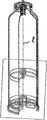
본 발명의 다른 바람직한 실시예에 따라서, 그러므로, 플라스틱 폴리머로 만들어진 용기가 다음의 청구항에서 한정된 바와 같이 제안되며, 내부 용기가 이러한 용기에 제공되는 것에 주목한다. 그러므로, 본 발명의 보다 구체적으로 한정된 실시예에 따른 이러한 이중 용기의 수단에 의해, 특히 유익한 적용은 20 내지 50 bar, 및 더욱 가능하게 100 bar까지, 또는 심지어 300 bar까지의 압력에 견디는 내부 보틀에서 압력 패키징을 만드는 것으로 이루어져서, 용기 내에서 문제가 일어나면, 외부 용기는 모든 것을 흡수하고, 이에 의해 퓨즈 안전 용기의 종류로서 기능한다. According to another preferred embodiment of the present invention, therefore, a container made of a plastic polymer is proposed as defined in the following claims, and an internal container is provided in such a container. Therefore, by means of this double container according to a more specific and definite embodiment of the invention, a particularly advantageous application is that of an inner bottle which withstands a pressure of from 20 to 50 bar, and more preferably up to 100 bar, or even up to 300 bar Pressure packaging, so that when a problem occurs in the container, the outer container absorbs everything, thereby acting as a kind of fuse safety container.
본 발명의 매우 주목할만한 실시예에 따라서, 완전히 충전되고 밀폐된 용기에 존재하는 액체에 발휘되는 압력은 모든 방향으로 줄지 않고 전송될 것이라는 파스칼의 법칙이 적용된다. 이러한 법칙은 여기에서 내부 용기를 포함하는 압력 용기에 적용되며, 압력 용기는 실제의 포괄적인 외부 용기로서 내부 용기를 완전히 밀폐한다. 내부 용기가 고압 하에 배치되고 외부 용기가 저압 하에 배치되면, 두 압력은 대기압보다 높고, 내부 용기 상의 잔류 압력은 내부 용기의 고압과 외부 용기의 저압(반대) 압력 사이의 차이와 동등하다. 이러한 것은 내부 용기가 정상적으로 높은 압력에 견딜 수 있도록 예상되는 것보다 가벼운 것으로 설계될 수 있다는 이점을 갖는다. 외부 용기에서 반대 압력을 일정하게 만들어내기 때문에, 내부 용기는 더욱 얇고 가벼운 것으로서 설계될 수 있다.According to a very noteworthy embodiment of the present invention, Pascal's law is applied that the pressure exerted on the liquid present in a fully charged and enclosed vessel will be transmitted without decreasing in all directions. This rule applies here to a pressure vessel containing an inner vessel, which completely encloses the inner vessel as an actual comprehensive outer vessel. When the inner vessel is placed under high pressure and the outer vessel is placed under low pressure, both pressures are higher than atmospheric pressure and the residual pressure on the inner vessel is equivalent to the difference between the high pressure of the inner vessel and the low pressure (negative) pressure of the outer vessel. This has the advantage that the inner vessel can be designed to be lighter than expected to withstand high pressures normally. Because the opposite pressure is constant in the outer container, the inner container can be designed to be thinner and lighter.
상기 내부 용기를 통합하는 목적은 음압이 다른 용기, 즉 외부 용기에 관계하여 생성된다는 조건 하에 소위 '대응-용기'의 생성으로 또한 유익하에 이루어질 수 있다. 그래서, 압력 조정기를 구성하는 압력 제어 디바이스로서 PVC형 용기 형태가 생성된다. 이러한 2개의 용기-시스템에서, 내부 용기는 압력 하에 배치되고, 2개의 차압은 두 용기를 위해 제어된다. The purpose of incorporating the inner vessel may also be beneficial in creating a so-called " counter-vessel " under the condition that the negative pressure is produced in relation to the other vessel, i.e. the outer vessel. Thus, a PVC type container shape is generated as a pressure control device constituting the pressure regulator. In these two vessel-systems, the inner vessel is placed under pressure and the two differential pressures are controlled for both vessels.
본 발명의 바람직한 실시예에 따라서, 보강재는 조인트가 차례로 부착되는 내부 용기를 저부에 통합하는 것에 의해 실행되고, 내부 압력 하에 있는 이러한 내부 용기는 추가로 용기에 의해 지지되고, 상기 내부 용기는 접착 또는 용접에 의해 가능하게 조인트없이 저부에 연결된다. 링들은 접착 또는 용접에 의해 고정될 수 있다. 그러므로, 적용 중 하나는 이중 용기 시스템의 수단에 의해 20 bar, 및 심지어 그 이상까지 작동하는 내부 용기에서 압력 패키징을 만드는 것으로 이루어지며, 퓨즈 용기로서 기능하는 외부 용기가 퓨즈 용기 내의 어떠한 고장을 제거하게 될 것이다. According to a preferred embodiment of the present invention, the stiffener is implemented by incorporating an inner container to which the joints are sequentially attached in the bottom, wherein such inner container under internal pressure is additionally supported by the container, Possibly connected to the bottom without joint by welding. The rings may be fixed by gluing or welding. Therefore, one of the applications consists in making pressure packaging in an internal vessel operating up to 20 bar, and even more, by means of a dual-vessel system, so that an external vessel functioning as a fuse container removes any failure in the fuse container Will be.
본 발명의 추가의 실시예에 따라서, 한층 더 높은 내부 압력에 저항하는 용기를 만들기 위해 서로로부터 일정 거리에 배치되는 특별한 보강 요소의 세트가 제공된다. 압력 용기의 내부 및/또는 외부에 서로로부터 일정 거리에 배치되는 보강 요소의 세트를 제공하는 것에 의해, 이것들은 점점 더 높은 내부 압력에 저항할 수 있다. According to a further embodiment of the invention, there is provided a set of special reinforcing elements arranged at a distance from each other to make a container resistant to a higher internal pressure. By providing a set of reinforcing elements that are arranged at a distance from each other inside and / or outside the pressure vessel, they can resist increasingly higher internal pressures.
특히, 상기 보강 요소는 용기의 주위에 필름을 권취 및/또는 수축시키는 것에 의해 얻어진다. 보다 상세하게, 상기 보강 요소는 용기에 연결되는 내부 지지링의 세트를 포함한다. In particular, the reinforcing element is obtained by winding and / or shrinking the film around the container. More particularly, the reinforcing element comprises a set of inner support rings connected to the container.
그 대안적인 실시예에 따라서, 보강 요소는 직접적으로 용기의 재료에 있는 두꺼운 부분 또는 보강 리브의 세트로 이루어지거나; 이 실시예의 또 다른 대안에 따라서, 상기 보강 요소는 유익하게 용기 블로잉 공정으로 직접 끼워질 수 있는 외부 지지링의 세트로 이루어지거나; 또는 그 추가의 대안적인 실시예에 따라서, 상기 외부 지지링은 메쉬 및/또는 그리드 및/또는 이미 통합된 그리드를 구비한 수축성 패키징 필름으로 대체될 수 있다.According to that alternative embodiment, the reinforcing element may consist of a set of thickened portions or reinforcing ribs directly in the material of the container; According to a further alternative of this embodiment, the reinforcing element advantageously consists of a set of external support rings that can be fitted directly into the container blowing process; Or according to a further alternative embodiment thereof, the outer support ring can be replaced by a shrinkable packaging film with a mesh and / or grid and / or an already integrated grid.
그 특정 실시예에 따라서, 상기 외부 지지링은 금속으로 만들어지고, 상기 외부 또는 내부 지지링은 또한 플라스틱으로 만들어질 수 있다. According to that particular embodiment, the outer support ring is made of metal, and the outer or inner support ring can also be made of plastic.
본 발명에 따른 압력 용기의 추가의 유익한 실시예에 따라서, 내부 또는 외부 용기 중 하나 또는 둘 모두는 투명하게 만들어진다. According to a further advantageous embodiment of the pressure vessel according to the invention, one or both of the inner or outer vessel is made transparent.
본 발명의 유익한 실시예에 따라서, 상기 플라스틱은 PET(폴리에틸렌 테레프탈레이트)로 이루어진다. 그러나, 플라스틱은 또한 폴리올레핀, 폴리에스테르, PETG, PBT 등과 같은 다른 플라스틱으로 이루어질 수 있다, 플라스틱의 적절한 선택으로, 부적절한 변형은 제어 하에서 보다 효과적으로 유지될 수 있다. 적절하게 고려되는 재료는, 재료가 제품의 필요조건, 특히 고압 저항, 가능하게 보다 높은 화학적 저항, 보다 높은 온도 저항에 적응될 수 있는 추가의 이점과 함께, 다른 플라스틱, 또는 폴리올레핀, 특히 폴리프로필렌 또는 폴리에틸렌, 폴리스티렌, PETG 또는 PBT와 같은 폴리에스테르, 폴리카보네이트, 폴리아미드 등, 또는 그 공중합체로 이루어지고, 이는 상기된 문제에 대해 개선된 해결책에 한층 더욱 좋게 기여한다. 그러므로, 상기 물리적 강도와 유익하게 결합될 수 있는 화학적 보강을 제공하여 몸체 강도에서 측정 가능한 증가를 이끄는 다양한 재료가 제안된다. According to an advantageous embodiment of the present invention, the plastic is made of PET (polyethylene terephthalate). However, plastics can also be made of other plastics, such as polyolefins, polyesters, PETG, PBT, etc. With a suitable choice of plastics, improper deformation can be maintained more effectively under control. A material considered appropriately is a plastic or polyolefin, especially polypropylene or polypropylene, with the added benefit that the material can be adapted to the requirements of the product, in particular high pressure resistance, possibly higher chemical resistance, Such as polyethylene, polystyrene, PETG or PBT, polycarbonate, polyamide, etc., or a copolymer thereof, which contributes even better to the improved solution to the above-mentioned problems. Therefore, a variety of materials are proposed that lead to measurable increases in body strength by providing chemical reinforcement that can be beneficially combined with the physical strength.
본 발명에 따른 압력 용기의 다른 실시예에 따라서, 용기는 용기의 몸체를 형성하는 맨틀 또는 슬리브의 상부 및 베이스 상의 적어도 하나의 단부 개구, 특히 2개의 단부 개구를 포함하며, 슬리브의 베이스측은 조인트의 수단에 의해 용기의 몸체에 부착되는 별개로 부가된 베이스에 의해 폐쇄되고, 슬리브는 클로저에 의해 상부에서 폐쇄된다.According to another embodiment of the pressure vessel according to the invention, the container comprises at least one end opening, in particular two end openings, on the top of the mantle or sleeve forming the body of the container and on the base, By means of a separately attached base attached to the body of the container, and the sleeve is closed at the top by a closure.
또 다른 제한은 이것들이 플라스틱 상의 장기간의 응력의 경우에 크리프를 보인다는 것이다. 그러나, 이러한 것은 플라스틱의 적절한 선택에 의해 상당히 해결될 수 있다. Another limitation is that they exhibit creep in the case of long-term stresses on the plastic. However, this can be largely solved by proper selection of plastics.
본 발명의 추가의 유익한 실시예에 따라서, 용기는 2축성으로 늘려질 수 있는 재료, 특히 주로 PET로 형성된 플라스틱 재료로 만들어진 예비 성형체로부터 기원하고; 보다 구체적으로, 이러한 것은 가능하게 PET를 사용하기 위하여 특히 아크릴이 내부로부터, 가능하게 또한 외부로부터 코팅된다. According to a further advantageous embodiment of the invention, the container originates from a pre-formed body made of a material which can be biaxially stretched, in particular a plastic material formed mainly of PET; More specifically, this is possibly coated from the inside, possibly also from the outside, for the use of PET, especially for acrylic.
보다 상세하게, 용기는 점차 보다 높은 압력 및/또는 온도에 저항하도록 플라스틱, 즉 변성 PET로 이루어진다. More specifically, the container is made of plastics, i.e. modified PET, to resist increasingly higher pressures and / or temperatures.
본 발명의 특정 실시예에 따라서, 상기 플라스틱은 배리어가 통합된 "PBA", 특히 통합된 포자(spore)를 가진 PETG로 지칭되는 소위 '폴리머 바이오 집합체(polymer bio-aggregate)'이다. 이러한 형태의 폴리머 바이오 집합체는 패키징 재료, 직물 섬유, 과립과 같은 산업용 제품의 제조 공정에서 특히 적용 가능한 폴리머 매트릭스에서 바이오-캡슐화를 통해 얻어지며, 특정 수명 스테이지 및 폴리머는 폴리머가 즉 그 용융점 이상의 온도에서 유체로 있는 짧은 시간 간극 내에 응집된다.According to a particular embodiment of the invention, the plastic is a so-called " polymer bio-aggregate " referred to as PETG with a barrier integrated PBA, in particular an integrated spore. This type of polymer bio-aggregate is obtained through bio-encapsulation in a polymer matrix, which is particularly applicable in the production process of industrial products such as packaging materials, textile fibers, granules, and certain lifetime stages and polymers, Lt; RTI ID = 0.0 > fluid < / RTI >
본 발명의 다른 실시예에 따른 용기는 단부 개구를 구비하고, 아래에서 절단되지 않는다. A container according to another embodiment of the present invention has an end opening and is not cut at the bottom.
본 발명의 특정 실시예에 따라서, 밸브는 용기 패키징의 추가된 베이스에 통합된다.According to a particular embodiment of the invention, the valve is incorporated in an added base of the container packaging.
본 발명의 또 다른 실시예에 따라서, 상기 조인트는 접착 조인트, 가능하게 또한 봉합 또는 용접 조인트를 또한 포함한다. 보다 구체적으로, 용접 조인트는 레이저, 유도 또는 초음파 조인트를 포함할 수 있다.According to another embodiment of the invention, the joint also comprises an adhesive joint, possibly also a sealing or welding joint. More specifically, the weld joint may comprise a laser, an induction or an ultrasonic joint.
본 발명의 용기의 추가의 실시예에 따라서, 용기는 예비 성형체로 만들어지고 용기는 감광성 및/또는 가스 민감성 제품, 특히 화장품, 세제 등과 같은 방사선 민감성 제품을 포함하도록 의도되며, 베이스 층 내로 통합되는 특정량의 첨가제와 함께 주로 플라스틱 베이스 재료로 이루어진 상기 적어도 하나의 베이스 층으로 만들어지며, 예비 성형체는 그 열 수축이 작업 온도의 사전 결정된 설정값에서 특정 설정값을 초과하지 않는 정도의 열 특성을 가지는 것으로 주목할 만하며, 특히, 상기 수축 설정값은 4% 내지 5%의 최대, 특히 3.5%의 최대, 바람직하게 1%까지 이른다. According to a further embodiment of the container of the present invention, the container is made of a preform and the container is intended to include radiation sensitive products such as photosensitive and / or gas sensitive products, especially cosmetics, detergents and the like, Said preform being made of said at least one base layer consisting predominantly of a plastic base material, said preform having a thermal characteristic such that its heat shrinkage does not exceed a specified set point at a predetermined set point of the working temperature Notably, in particular, the shrinkage setting value reaches a maximum of 4% to 5%, in particular a maximum of 3.5%, preferably up to 1%.
특히, 상기 주 베이스 층은, 외부 방사선, 특히 전자기 방사선, 더욱 특히 광에 대해 그 내부를 보호하기 위하여 소위 블렌드의 형성과 함께, 1wt% 내지 20wt%, 특히 5 내지 15wt%, 더욱 특히 대략 10wt%의 특정량의 주 첨가제를 포함하며, 특히 첨가제는 폴리머 첨가제, 특히 열가소성 폴리머 첨가제에 의해, 가능하게 폴리카보네이트 블렌드의 형성과 함께 폴리카보네이트에 의해, 또는 PEN, PETN05에 의해, 또는 심지어 폴리프로필렌 또는 PET 첨가제에 의해 형성되고; 재료가 고 내압성, 고 내화학성, 고 내온성과 같은 제품의 요구조건에 가장 잘 적응될 수 있다는 추가의 이점을 갖는다. In particular, the main base layer can comprise from 1 wt% to 20 wt%, in particular from 5 to 15 wt%, more particularly from about 10 wt% to about 10 wt%, with the formation of so-called blends to protect the interior against external radiation, In particular the additive, by means of a polymer additive, in particular a thermoplastic polymer additive, possibly by polycarbonate with the formation of a polycarbonate blend, or by PEN, PETNO5, or even by polypropylene or PET Formed by an additive; The material has the additional advantage that it can best be adapted to product requirements such as high pressure resistance, high chemical resistance and high temperature resistance.
예비 성형체는 단층 구조, 가능하게 또한 다층 구조, 특히 상기 주 베이스 층으로 이루어진 3층 구조를 가질 수 있으며, 배리어 층, 특히 광 및/산소 배리어로서 작용하는 중간층이 통합되고, 중간층은 사실상 모든 전송된 광 및/또는 산소를 여과할 수 있는 2차 플라스틱 재료로 만들어진 된다. The preform may have a single-layer structure, possibly also a multi-layer structure, in particular a three-layer structure consisting of the main base layer, in which the intermediate layer, which in particular acts as a light and / It is made of a secondary plastic material capable of filtering light and / or oxygen.
본 발명의 또 다른 실시예에 따라서, 가스 배리어는 대응하는 가스 흡수를 갖는 배리어 재료로 이루어진 벽의 층 중 하나, 특히 중간층 내로 통합되며; 및/또는 첨가제는 벽에 있는 능동 또는 수동적 배리어 형성으로 용기에 수용된 제품에 악영향을 시약으로 중화하는 효과를 가지며; 및/또는 첨가제는 상기 제품의 열화로부터 기원하는 가스 형성에서 중화 효과를 가지며; 및/또는 상기 첨가제는 외부 물질, 특히 벽에 있는 관련 가스 배리어의 형성 하에서 산소 및/또는 이산화탄소 모두 중화하는 효과를 갖고; 및/또는 산소 배리어는 산소 흡수로 하나 이상의 층에 있는 PET를 폴리에스테르 배리어로 대체하는 것에 의해 용기 벽 또는 예비 성형체 벽으로 통합된다.According to another embodiment of the present invention, the gas barrier is incorporated into one of the layers of the wall made of a barrier material with a corresponding gas absorption, in particular into the intermediate layer; And / or the additive has the effect of neutralizing the adverse effect on the product contained in the container with the reagent by active or passive barrier formation on the wall; And / or the additive has a neutralizing effect in the gas formation originating from the deterioration of said product; And / or said additive has the effect of neutralizing both oxygen and / or carbon dioxide under the formation of an external material, particularly the associated gas barrier in the wall; And / or the oxygen barrier is incorporated into the vessel wall or preform wall by replacing the PET in one or more layers with a polyester barrier with oxygen absorption.
본 발명의 추가의 실시예에 따라서, 압축 패키징은 적어도 2개의 챔버로 이루어진 다중 챔버 시스템에 의해 형성된다. 이러한 이원 시스템의 경우에, 용기는 관련 종속항에서 한정된 바와 같이 아래에서 폐쇄되고, 챔버 파티션은 용기에 다른 챔버들을 생성하도록 끼워지고, 이 경우에, 챔버 파티션은 적어도 하나의 압력 제어 밸브 또는 가스 처리 밸브를 구비할 수 있다. 특히, 이러한 압력 제어 밸브는 압력 제어 밸브에 수단에 의해 외부로부터 간접적으로 개방될 수 있는 클로저일 수 있어서, 하나의 챔버의 내용물은 다른 챔버와 접촉할 수 있으며, 챔버들은 압력하에 있을 수 있거나 또는 압력하에 있지 않을 수 있고, 가능하게, 저부측 및 상부측은 동일한 폐쇄편, 특히 클로저의 수단에 의해 폐쇄되고, 특히 상기 커버는 도우징 밸브(dosing valve), 또는 가능하게 스크루 캡 또는 다른 클로저로 이루어진다. According to a further embodiment of the invention, the compression packaging is formed by a multi-chamber system consisting of at least two chambers. In the case of such a binary system, the vessel is closed down as defined in the relevant subclause, and the chamber partitions are fitted to create other chambers in the vessel, in which case the chamber partitions are subjected to at least one pressure control valve or gas treatment A valve may be provided. In particular, such a pressure control valve may be a closure that can be opened indirectly from the outside by means to the pressure control valve such that the contents of one chamber may be in contact with another chamber, and the chambers may be under pressure, And possibly the bottom side and the top side are closed by means of the same closing piece, in particular by a closure, in particular the cover is made up of a dosing valve, or possibly a screw cap or other closure.
특히 유익한 실시예에 따라서, 압력 용기는 한편으로는 상기된 바와 같은 이중 용기의 조합된 실시로, 다른 한편으로는 다중 챔버 시스템으로 이루어진다.According to a particularly advantageous embodiment, the pressure vessel consists of a combined implementation of a double vessel on the one hand, as described above, on the other hand, a multi-chamber system.
본 발명은 또한 상기된 압력 용기 패키징의 제조 방법에 관한 것이며, 여기에서 사용된 용기는 튜브를 얻기 위하여 용기의 연속적인 절단으로 하나의 단계 공정에 의해 만들어지며, 압력 수단은 특히 가스 처리를 통해 대기압으로부터 대략 20 bar, 보다 가능하게 100 bar까지 충전 제품으로 패키징 용기를 압축하도록 용기에 끼워진다. 용기는 2-단계 공정에 의해 형성될 수 있다. 용기는 절단 없이 사출성형에 의해 직접 형성될 수 있다. 용기는 그 후에 여전히 절단될 수 있다. The present invention also relates to a method of manufacturing a pressure vessel packaging as described above wherein the container used is made by a one step process with successive cutting of the container to obtain a tube, To about 20 bar, more preferably to about 100 bar, of the packaging container. The vessel may be formed by a two-step process. The container can be formed directly by injection molding without cutting. The container may then still be severed.
본 발명의 방법의 특정 실시예에 따라서, 가요성 내부 용기 또는 백은 충전 제품이 외벽 또는 압력 가스(가스, 공기)와 접촉하는 것을 방지하도록 용기 내에 삽입되고, 특히 가요성 내부 용기는 블로잉에 의해 용기 내에 통합된다. According to a particular embodiment of the method of the present invention, the flexible inner container or bag is inserted into the container to prevent the filling product from contacting the outer wall or the pressurized gas (gas, air), and in particular, Lt; / RTI >
용기 내에서의 압축은 밀봉구의 수단에 의해 자기 페쇄 가능한 개구를 통해 폐쇄 가능한 하부 밸브를 통해 수행될 수 있고, 이러한 밀봉구는 가요성 플라스틱으로 만들어진 튜브 요소로 이루어지며, 특히 용기 내에서의 압축은 폐쇄 가능한 상부 밸브를 통해, 특히 자기 페쇄 가능한인 소위 "엄브렐러 플러그(umbrella plug)", 또는 소위 "니콜슨 플러그(Nichelson plug)"를 통해 일어날 수 있다.The compression in the container can be carried out by means of a seal through a self-closing capable opening through a lower valve, which consists of a tubular element made of flexible plastic, in particular compression in the container, Through a possible upper valve, in particular via a so-called "umbrella plug" which is self-closing, or a so-called " Nichelson plug ".
본 발명의 방법의 보다 특별한 실시예에 따라서, 용기는 사출 성형 예비 성형체를 스트레칭 및 블로잉에 의해 플라스틱으로 만들어지며, 예비 성형체는 높은 열 치수 안정성을 갖기 위하여 높은 결정화도를 갖고, 상기 결정화도는 배향 유도 결정화도를 형성하며, 특히 결정화도는 30%보다 높고, 특히 35 내지 40%이다. According to a more particular embodiment of the method of the present invention, the container is made of plastic by stretching and blowing the injection-molded preform, the preform has a high degree of crystallinity to have high thermal dimensional stability, And particularly the degree of crystallinity is higher than 30%, especially 35 to 40%.
특히, 상기 용기는 PET 블렌드 또는 특히 그 극히 낮은 레벨에 따라서 보다 큰 열에 대해 저항하는 상이한 폴리에스테르를 가진 공중합체로 만들어지고, 특히, 상기 폴리에스테르는 폴리에틸렌 나프탈레이트; 폴리트리메틸렌 나프탈레이트에 의해; 또는 PETN-5형 400105로서 공지된 플라스틱 재료에 의해 형성된다. In particular, the container is made of a PET blend or a copolymer with different polyesters which are resistant to greater heat, in particular according to their extremely low level, and in particular the polyester is selected from the group consisting of polyethylene naphthalate; By polytrimethylene naphthalate; Or a plastic material known as PETN-5 type 400105.
또한, 본 발명의 특이성 및 특징은 추가의 종속항에서 한정된다. 추가의 상세는 첨부된 도면을 참조하여 본 발명의 일부 실시예에 대해 다음에 도시된다. 동일한 도면부호는 본 명세서에서 동일 또는 유사한 요소를 인용한다. The specificity and characteristics of the present invention are further defined in the dependent claims. Additional details are set forth below in some embodiments of the invention with reference to the accompanying drawings. The same reference numerals refer to the same or similar elements in this specification.
도 1 내지 도 15는 몇개의 도면, 전체 및/또는 부분적인 도면에서 변형을 가진 각 경우에서, 본 발명에 따른 용기의 실시예를 각각 도시하고,
도 1은 본 발명에 따른 용기의 제1 실시예의 저부 섹션의 혼합 결합된 부분적인 단면 사시도;
도 2는 도 1에 도시된 본 발명에 따른 용기의 실시예의 도시의 완료된 측면도;
도 3은 선행의 도면에 도시된 용기의 실시예와 유사한 결합도이지만 그 상부를 도시한 도면;
도 4는 본 발명에 따른 용기의 제2 실시예의 저부 섹션의 부분 단면 결합 사시도;
도 5는 도 4에 도시된 본 발명에 따른 용기의 실시예의 도 2와 유사한 측면도;
도 6은 본 발명에 따른 용기의 제3 실시예의 도 1과 에서와 유사한 도면;
도 7은 도 4에 도시된 본 발명에 따른 용기의 제3 실시예의 도 5와 유사한 측면도;
도 8은 본 발명에 다른 제4 실시예의 도 1에 따른 상세도에 관하여 도 2와 유사한 완료된 측면도;
도 9는 그 종방향 측부가 측면으로 제거된 선행 도면에 도시된 완료 용기의 추가의 완료 혼합된 측면 사시도;
도 10 및 도 11은 본 발명에 따른 용기의 여전히 추가의 실시예의 선행의 도 8 및 도 9에서와 유사한 도면;
도 12 및 도 13은 본 발명에 따른 용기의 추가의 실시예의 도 8 및 도 9와 유사한 도면;
도 14는 도 15에서 측면으로 도시된 바와 같은, 본 발명에 따른 용기의 추가 실시예의 도 3과 유사한 평면도;
도 16은 본 발명에 따른 용기의 추가의 실시예의 각각 도 2 및 도 3에 도시된 바와 같은 상기 저부 및 상부의 표현과 유사한 혼합도;
도 17은 선행의 도 16에서 도시된 바와 같은 용기의 추후 실시예의 도 15와 유사한 도면;
도 18 및 도 19는 각각 선행의 도 16 및 도 17에 도시된 바와 같은 용기의 추가 실시예의 유사한 도면;
도 20 및 도 21은 본 발명에 다른 용기의 추가 실시예의 각각 도 5 및 도 4에 도시된 바와 유사한 부분 절단 저부 섹션의 도면;
도 22 및 도 23은 다중 챔버 시스템을 구비한 본 발명에 따른 용기의 추가 실시예의 선행의 도 20 및 도 21에서와 유사한 도면;
도 24 및 도 25는 도 25에서 도시도니 제1 연속 저부를 각각 구비하는 도 9 및 도 8에서와 차례로 유사한 도면;
도 26 및 도 27은도 27에 도시된 다른 저부 마감을 가진 선행의 도 24 및 도 25와 유사한 도면;
도 28 및 도 29 도 29에 도시된 다른 플로어 마감을 구비한 도 24 및 도 25와 유사한 도면;
도 30은 도 26에 도시된 바와 같은 용기의 추가 실시예의 단면도;
도 31은 저부 및 상부를 구비한 선행의 도 30에 도시된 용기의 상세 확대 분해도;
도 32 및 도 33은 본 발명에 따른 용기의 추가의 실시예의 도 30 및 도 31과 각각 유사한 도면이며, 도 34는 그 확대 상세도;
도 35 및 도 36은 본 발명에 따른 용기의 추가 실시예의 도 28 및 도 29와 각각 유사한 도면;
도 37은 2-챔버 시스템을 구비한 도 23에 도시된 본 발명에 따른 용기의 완료된 도면;
도 38은 도 23과 유사한 도 37의 확대 상세도;
도 39는 끝에서 두번째의 도 37에 도시된 바와 같은 상기 2-챔버 시스템 용기의 부분 단면도;
도 40은 이중 용기 시스템을 구비한 추가의 실시예에 따른 도 37에 도시된 바와 같은 용기를 도시한 도면;
도 41은 선행의 도면에 따른 다중 챔버 시스템을 구비한 이중 용기의 바로 앞의 도면과 유사한 도면;
도 42는 도 23과 유사한 도 41의 확대 상세도;
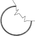
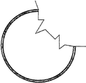
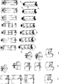
끝으로, 도 43 내지 도 48은 상이한 표현의 보강 요소를 각각 구비하는 본 발명에 따른 보강된 용기 벽의 특정 실시예를 쌍으로 각각 도시하며, 각각 도 43, 도 45 및 도 47에 있는 선 A-A, B-B 및 C-C에 따른 단면도;
도 49는 상기에서 설정된 바와 같은 당양한 실시예에 대한 종합적인 변형을 위한 요약을 도시하며;
도 50은 본 발명에 따른 용기의 시리즈의 종합된 현실적 도면을 도시하며;
도 51a 내지 도 50i는 본 발명에 따른 상기 용기의 현실적으로 도시된 저부 부분의 다수의 종합적인 도면을 도시한다.1 to 15 show an embodiment of a container according to the invention, respectively, in each case with modifications in several figures, in whole and / or partial drawings,
BRIEF DESCRIPTION OF THE DRAWINGS Figure 1 is a cross-sectional, partially sectional, perspective view of a bottom section of a first embodiment of a container according to the present invention;
Figure 2 is a side view of a completed embodiment of a container according to the invention shown in Figure 1;
Figure 3 is a top view of a coupling similar to but similar to the embodiment of the container shown in the preceding figures;
4 is a partial cross-sectional perspective view of a bottom section of a second embodiment of a container according to the present invention;
Figure 5 is a side view similar to Figure 2 of the embodiment of the container according to the invention shown in Figure 4;
Figure 6 is a view similar to that of Figure 1 of a third embodiment of a container according to the invention;
Figure 7 is a side view similar to Figure 5 of a third embodiment of the container according to the invention shown in Figure 4;
Fig. 8 is a side view similar to Fig. 2 of a fourth embodiment according to the present invention, in relation to the detail view according to Fig. 1;
Figure 9 is a further finished mixed side perspective view of the finished vessel shown in the preceding figure with its longitudinal sides removed laterally;
Figs. 10 and 11 are diagrams similar to the previous Figs. 8 and 9 of still further embodiments of a container according to the invention; Fig.
Figures 12 and 13 are views similar to Figures 8 and 9 of a further embodiment of a container according to the invention;
Figure 14 is a plan view similar to Figure 3 of a further embodiment of a container according to the present invention, as viewed sideways in Figure 15;
Figure 16 is a blend similar to the representation of the bottom and top as shown in Figures 2 and 3, respectively, of a further embodiment of a container according to the invention;
Figure 17 is a view similar to Figure 15 of a later embodiment of the container as shown in the preceding Figure 16;
Figures 18 and 19 are similar views of further embodiments of the container as shown in Figures 16 and 17, respectively, preceding;
Figures 20 and 21 are views of a partial cut bottom section similar to that shown in Figures 5 and 4, respectively, of a further embodiment of a container according to the present invention;
Figures 22 and 23 are similar to previous Figures 20 and 21 of a further embodiment of a container according to the invention with a multi-chamber system;
FIGS. 24 and 25 are views similar to FIG. 9 and FIG. 8, respectively, which respectively have a first continuous bottom in the view of FIG. 25;
Figs. 26 and 27 are similar to Figs. 24 and 25 of the preceding figures with another bottom end shown in Fig. 27;
Figures 28 and 29 are similar to Figures 24 and 25 with the other floor finishes shown in Figure 29;
Figure 30 is a cross-sectional view of a further embodiment of a container as shown in Figure 26;
31 is a detail enlarged exploded view of the container shown in the preceding FIG. 30 with a bottom and an upper portion;
Figures 32 and 33 are views similar to Figures 30 and 31, respectively, of a further embodiment of a container according to the present invention, and Figure 34 is an enlarged detail view thereof;
Figures 35 and 36 are views similar to Figures 28 and 29, respectively, of a further embodiment of a container according to the present invention;
Figure 37 is a completed view of a container according to the present invention shown in Figure 23 with a two-chamber system;
Figure 38 is an enlarged detail view of Figure 37, similar to Figure 23;
FIG. 39 is a partial cross-sectional view of the two-chambered system container as shown in FIG. 37, second from the end; FIG.
Figure 40 illustrates a container as shown in Figure 37 according to a further embodiment with a dual container system;
Figure 41 is a view similar to the preceding figure of a dual vessel with a multi-chamber system according to the preceding figures;
Figure 42 is an enlarged detail view of Figure 41, similar to Figure 23;
Finally, FIGS. 43-48 illustrate, in pairs, a specific embodiment of a reinforced vessel wall according to the present invention, each having a different representation of the reinforcing elements, Sectional views along BB and CC;
FIG. 49 shows a summary for a general variation on a variant embodiment as set forth above; FIG.
Figure 50 shows an integrated realistic view of a series of containers according to the present invention;
Figures 51A-50I illustrate a number of general views of the bottom portion of the container shown in accordance with the present invention.
일반적으로, 본 발명은 상부, 중앙부 및 저부를 구비한 패키징으로서 기능하는 압축 용기에 관한 것으로, 그 상부 부분은 개구를 구비하고, 압력 용기는 개구를 통해 충전될 수 있으며, 밸브 또는 클로저는 통합될 수 있고, 패키징은 특히 대략 55℃의 온도에서 약 20 bar 및 100 bar 이상, 또는 심지어 300 bar까지의 범위의 압력 하에 있다. In general, the present invention relates to a compression vessel that functions as a package with top, middle and bottom portions, the top portion of which has an opening, the pressure vessel can be filled through an opening, And the packaging is particularly under pressure at a temperature of about 55 DEG C of about 20 bar and at least 100 bar, or even up to 300 bar.
베이스 부분은 용기의 아래에 배치되는 별도의 구성 요소를 형성하는 한편, 용기를 압축하기 위해 밸브를 구비한다. 중앙부는 예를 들어 원통형 또는 각기둥 프로파일을 갖는다.The base portion forms a separate component disposed under the container, while having a valve to compress the container. The central portion has, for example, a cylindrical or prismatic profile.
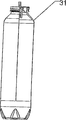
압력 용기는 조인트(13)에 의해 용기(1)에 부착되는 베이스(2)에 의해 저부에서 밀봉된다. 조인트(13)는 접착, 봉합 또는 용접에 의해 얻어질 수 있다. 또는 용기는 폐쇄 커버 베이스(18)에 의해 저부에서 폐쇄된다. 또한, 용기(1)는 도우징 밸브(17) 또는 스크류 캡 또는 다른 클로저일 수 있는 커버(5)로 폐쇄된다.The pressure vessel is sealed at the bottom by a
용기는 별도로 끼워지는 베이스를 가질 수 있거나, 또는 가능하게 이와 원피스로 만들어질 수 있다.The container may have a base to be fitted separately, or possibly be made of a one-piece with it.
주 용기(1)는 종방향 축선(ℓ)을 따라서 연장하는 실질적으로 원통형인 몸체(22), 상부에 있는 클로저(5), 분리 또는 분리되지 않던간에 아래에 준비된 바와 같은 다양한 형상을 취할 수 있는 추가 베이스(21)를 포함한다. 원통형 몸체(22)는 바람직하게 플라스틱, 특히 투명 플라스틱으로 만들어져서, 용기에 충전된 제품의 레벨은 사용자에게 보여질 수 있다. 이러한 것은 반투명, 맑은 또는 투명한 벽으로서 이해되어야 한다. 몸체(22)를 형성하도록 선택된 특정 재료는 용기에 수용된 충전 제품에 대하여 화학적으로 비활성이어야 하며, 또한 연속성 또는 불연속성 충전 제품의 압축 패키징으로 이루어진 의도된 사용을 위하여 충분한 강도 및 내구성을 제공하여야 한다.The
적합한 재료의 예는 아래에 주어진다.Examples of suitable materials are given below.
원통형 또는 각기둥형 몸체는 상기 용기를 제조하는 대응 방법과 함께 추가로 기술되는 바와 같은 사출 성형 기술을 사용하는 것에 의해 또는 압출에 의해 제조될 수 있다. 압력 용기 벽(22)에 충분한 강도를 주도록, 보강 요소는 압력 용기의 벽(22)에 적어도 제공된다. 보강 요소는 유익하게 용기 몸체 벽(22) 주위에 배열되는 주변 보강 요소의 형태로 제공될 수 있는 기계적 보강 요소(30)의 제1 예로 이루어진다. 그러므로, 원통형 벽을 위하여, 보강 요소들은 용기의 종방향 축(ℓ)에 대해 직각으로 연장하는 영역 내로 유익하게 연장하는 원형 링들이며, 이에 의해 벽 상에서 링의 보강 효과의 최적의 사용을 만든다. The cylindrical or prismatic body can be manufactured by using an injection molding technique as described further with the corresponding method of making the container or by extrusion. The reinforcing element is provided at least in the
바람직하게, 몇개의 보강 링은 용기 벽을 따라 제공되며, 특히 홀수에 따라서, 압력 용기의 내부 및/또는 외부에서 각각 서로로부터 상호 거리를 두고 배치되어서, 특히 보강 링들이 서로로부터 등거리에 배제공되면, 중앙의 링은 기본적으로 용기에서 가장 바라던 영역인 용기 벽(22)의 중간 높이에 적절하게 끼워질 수 있다. Preferably, some of the reinforcing rings are provided along the wall of the container, and, in particular, according to the odd number, are arranged at mutual distance from one another, both inside and / or outside the pressure vessel, especially when the reinforcing rings are provided equidistantly from each other , The center ring can be suitably fitted at the middle height of the
그러나, 보강 링은 특히 몸체 상부 및 저부 단부로부터 각각 그 중앙 섹션을 향하여 감소하는 거리로 상이한 종방향 분포에 따라서 또한 끼워질 수 있고, 그러므로, 연속되는 보강 링들 사이의 중간 공간은 몸체의 중간을 향하여 감소한다. 실제로, 이러한 것은 용기의 가장 바라던 섹션, 즉 중간 섹션에서 증가된 강도를 만든다. However, the reinforcing ring can also be fitted also in accordance with different longitudinal distributions, in particular with decreasing distances from the upper and lower ends of the body, respectively, towards its central section, and therefore the intermediate space between successive reinforcing rings is directed towards the middle of the body . In practice, this creates increased strength in the most desired section of the vessel, the middle section.
보강 요소(31, 32)는 유익하게 특히 외향하는 상부를 가진 실질적으로 반원형 단면을 구비한 둥근 프로파일을 가진다. 이러한 프로파일 패턴 때문에, 국부적 장력이 용기 벽과 관계하여 최대 장력을 발휘하도록 서로 추가되어서, 가능하게 바깥쪽으로 굽혀지거나 또는 팽창하는 그 경향이 억제된다. The reinforcing
보강 링은 바람직하게 도 49에 도시된 바와 같이 연속적인 링들 사이의 공간의 절반보다 작은, 바람직하게 심지어 상당히 작은, 또는 더욱 작은 공간에 머무르는 폭을 가져서, 평균 용기 벽 두께는 상대적으로 작은 값을 갖는다.The reinforcing ring preferably has a width that is less than half, preferably even significantly less, or smaller than the space between successive rings, as shown in Figure 49, so that the average vessel wall thickness has a relatively small value .
상기 보강 링은 본질적으로 외벽에 제공되지만, 예를 들어 적어도 그 약한 지점에서, 필요한 벽의 강도를 보장하기 위하여 가능하게 외벽에 있는 것들과 결합하여 내벽에 또한 끼워질 수 있다.The reinforcing ring is provided essentially in the outer wall, but can also be fitted, for example at least in its weakest point, to the inner wall in combination with those on the outer wall, possibly in order to ensure the strength of the required wall.
종방향 또는 방사상 리브와 같은 다른 형태의 리브는 의도적으로 본 발명에서 사용되지 않는다. 내부로부터 작용하는 압력의 영향 하에서 용기 벽의 비 변형의 관점에서 그 효율은 실제로 어쨌든 상당히 적다. 그러므로, 종방향 축선(ℓ)에 대해 직각인 영역 내로 연장하는 주변 보강 리브 또는 링은, 상기된 다른 형태의 보강 리브보다 단지 약간 또는 상당히 적은 압력의 작용 하에서 용기 벽의 가능한 팽창에 대한 경향을 방해하는데 상당히 더욱 효과적이다. 그러므로, 이러한 보강 요소는 높은 내부 압력에 대한 용기 저항을 만드는 역할을 한다. 보강 요소는 또한 용기에 조인트되는 내부 지지링의 세트에 의해 용기 주위에 필름을 감싸고 및/또는 수축시키는 것에 의해 얻어질 수 있다. 대안적으로, 상기 보강 요소는 용기의 재료에 직접적으로 두꺼운 부분 또는 보강 리브의 세트로; 용기 블로잉 공정에서 유익하게 직접 끼워질 수 있는 외부 지지링의 세트; 메쉬 및/또는 그리드 및/또는 그리드가 이미 통합된 수축 패키징 필름에 의해 이루어질 수 있다.Other types of ribs such as longitudinal or radial ribs are not intentionally used in the present invention. The efficiency in terms of deformation of the vessel wall under the influence of the pressure acting from the inside is actually quite small anyway. Therefore, peripheral reinforcement ribs or rings that extend into a region orthogonal to the longitudinal axis (l) interfere with the tendency for the container wall to expand possible under the action of pressure that is only slightly or significantly less than the other types of reinforcing ribs described above Which is considerably more effective. Thus, these reinforcing elements serve to create a container resistance to a high internal pressure. The reinforcing element can also be obtained by wrapping and / or shrinking the film around the container by means of a set of inner support rings which are jointed to the container. Alternatively, the reinforcing element may be provided as a set of thickened portions or reinforcing ribs directly in the material of the container; A set of external support rings that can be advantageously directly fitted in the container blowing process; Mesh and / or grid and / or grid may be made by already incorporated shrink packaging films.
가능하게, 상기 외부 지지링은 금속으로 만들어 질 수 있으며, 상기 외부 또는 내부 지지링은 마찬가지로 플라스틱으로 만들어질 수 있다. Possibly, the outer support ring can be made of metal, and the outer or inner support ring can likewise be made of plastic.
보강은 바람직하게 차례로 조인트로 베이스에 부착되는 내부 용기를 삽입하는 것에 의해 실행되고, 내부 압력 하에 있는 내부 용기는 주 용기에 의해 추가로 지지되고, 내부 용기는 가능하게 조인트없이 접착 또는 용접에 의해 주 용기에 연결된다. 링은 접착 또는 용접에 의해 부착될 수 있다.The reinforcement is preferably carried out by inserting an inner container, which in turn is attached to the base with a joint, wherein the inner container under internal pressure is additionally supported by the main container, Lt; / RTI > The ring may be attached by gluing or welding.
테스트가 용이한 예는 예를 들어 내부적으로 용기를 6 bar로 압축하는 단계, 상부를 따라서 2.5 bar를 더하여 변형을 측정하는 단계, 및 다시 변형을 측정하는 단계로 이루어진다. 그런 다음, 상기 용기가 6 bar를 견디는 것이 필요하지만, 상기 용기가 2.5 bar 하에 있으면, 나중의 2.5 bar 압력은 결과적으로 내부 용기에서 반대 방향으로 작용하는 것으로 고려될 수 있고, 그 결과, 내부 용기가 견뎌야만 하거나 또는 그 벽 주위에서 실제로 느끼는 압력은 실제로 3.5 bar, 즉 6-2.5이다. 주요한 적용은 내부 용기가 보다 가볍게 만들어질 수 있다는 것이다. 실제로, 그 벽은 내부 용기가 더 이상 6 bar에 견디지 못하고 단지 3.5 bar만 견뎌야만 하여, 벽이 더욱 얇아질 수 있다. 그러므로, 이중 용기의 또 다른 이점은 파스칼의 법칙의 적용이라는 것이며, 두 용기 중 하나가 견뎌야만 하는 저압이 수반된다는 효과가 얻어지며, 이는 특정 적용에 아주 유용하다. 그러므로, 내부 용기는 기본적으로 기계적으로 적은 응력을 받는다. 이러한 용기는 또한 더욱 가벼워질 수 있다. 이는 상당한 장점이며, 즉, 보다 가벼운 용기는 그 안에 생성된 반대 압력 때문에 만들어질 수 있다. 이 예에서, 내부 용기는 압력 용기로서 작용하며, 압력 하에 있는 내부 용기는 이를 둘러싸는 외부 용기를 실제로 보호하고, 이에 의해, 대응 용기로서 실제로 작용하고; 그래서, 상기 내부 용기는 베이스 용기를 위하여 감소된 압력으로 베이스 용기 상에 음압을 발휘하고, 즉 다른 용기의 작용 하에서 한 용기를 위하여 보다 낮은 압력으로 상기 이중 용기 시스템에 음압을 발휘한다.Examples of ease of testing include, for example, compressing the container internally to 6 bar, adding 2.5 bar along the top to measure the deformation, and measuring the deformation again. Then, if it is necessary for the vessel to withstand 6 bar, if the vessel is below 2.5 bar, the latter 2.5 bar pressure can consequently be considered to act in the opposite direction in the inner vessel, The pressure actually felt around or around the wall is actually 3.5 bar, or 6-2.5. The main application is that the inner container can be made lighter. In fact, the wall can not withstand the internal vessel anymore than 6 bar and only withstands 3.5 bar, so that the wall can become thinner. Therefore, another advantage of the double vessel is that it is the application of Pascal's law, which has the effect of involving a low pressure that one of the two vessels must endure, which is very useful for certain applications. Therefore, the inner container is basically subjected to a mechanical stress. Such containers can also be lighter. This is a significant advantage, i.e. a lighter container can be made due to the opposite pressure created therein. In this example, the inner vessel acts as a pressure vessel, and the inner vessel under pressure physically protects the outer vessel surrounding it, thereby actually acting as a corresponding vessel; Thus, the inner container exerts a negative pressure on the base container at a reduced pressure for the base container, i.e., exerts a negative pressure on the double container system at a lower pressure for one container under the action of another container.
병 용기의 경우에, 병 안에 있는 병은 하나의 챔버이며, 내부 병은 외부 병의 추가의 보강으로서 역할을 한다. 그러므로, 내부 용기는 압력 조정기를 통해 압축되고, 이에 의해, 2개의 다른 압력은 압력 경도(pressure gradient)(ΔΡ), 특정 압력차(ΔΡ)인 내부 용기와 베이스 용기 사이의 차이의 생성과 함께 지금 제어된다. 이 ΔΡ에 의해, 상기 내부 용기는 보다 가볍게 만들어질 수 있다. 이러한 것은 파스칼의 법칙의 이러한 응용이다.In the case of a bottle container, the bottle in the bottle is one chamber, and the inner bottle serves as an additional reinforcement of the outer bottle. Therefore, the inner vessel is compressed through the pressure regulator, whereby two different pressures are created with the generation of the difference between the inner vessel and the base vessel, that is, the pressure gradient (DELTA P), the specific pressure difference Respectively. By this? P, the inner container can be made lighter. This is the application of Pascal's law.
상기된 기계적 보강 요소에 더하여, 후술하는 바와 같이, 화학적 보강재가 가능하게 마찬가지로 사용될 수 있다. 용기 벽에 축적된 보강 효과를 달성하고, 이에 의해 작용하는 압력에 관하여 강성을 상당히 증가시키기 위하여, 상기 화학적 보강 요소는 가능하게 상기 기계적 보강 요소와 결합하여 사용되고, 작용하는 압력에도 불구하고 용기 벽의 가능한 완벽한 보강을 이끈다. In addition to the mechanical reinforcement elements described above, chemical reinforcements may also be used as possibly as described below. In order to achieve the reinforcing effect accumulated on the container wall and to considerably increase the stiffness with respect to the pressure acting thereby, the chemical reinforcing element is preferably used in combination with the mechanical reinforcing element, It leads to perfect reinforcement as much as possible.
목표는, 그 중에서도 밀봉구(4)에 의해 자기 폐쇄 가능한 개구(3)를 통해 폐쇄 가능한 상부 밸브(17) 및/또는 폐쇄 가능한 하부 밸브를 통해 일어나는, 특히 55℃의 온도에서, 대략 20 bar, 및 100 bar 이상, 또는 심지어 300 bar까지의 범위에 있는 압력 하에서 패키징하기 위한 충전 제품을 가진 패키징, 특히 가스로 적어도 압축하는 것이며, 밀봉구(4)는 가요성 플라스틱으로 만들어진 작은 튜브; 및/또는 모두 상업적으로 시판중인 상기 자기 폐쇄 가능한 "엄브렐러 플러그"(6); 또는 상기 2-단계 "니콜슨 플러그"(7)이다. The target is at least about 20 bar, preferably at least about 20 bar, at a temperature of 55 [deg.] C, which occurs via the
용기(1 또는 1')가 높은 내부 압력에 저항하도록 하기 위하여, 본 발명은 다양한 방식으로;In order for the container (1 or 1 ') to withstand a high internal pressure, the present invention may be applied in various ways;
서로로부터 일정 거리에 위치되고 접착 또는 용접에 의해 용기에 연결되는 내부 지지링(8 및 8')에 의해; 및/또는 By internal support rings 8 and 8 'located a certain distance from each other and connected to the vessel by gluing or welding; And / or
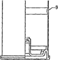
용기(1)의 재료에 직접적으로 있는 두꺼운 부분 또는 보강 리브(9 및 9')에 의해; 및/또는 By thickened portions or reinforcing
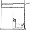
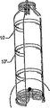
서로로부터 일정 거리에 위치되고 접착 또는 용접에 의해 또는 간단히 조인트없이 연결되는 외부 지지링(10 및 10')에 의해; 및/또는 By external support rings 10 and 10 'which are located a certain distance from each other and which are connected by adhesive or welding or simply without joints; And / or
차례로 조인트에 의해 베이스(2)에 부착되는 내부 용기(14)를 삽입하는 것에 의해, 용기를 보강하는 것으로 이루어지며; And reinforcing the container by inserting an inner container (14) which in turn is attached to the base (2) by a joint;
8과 8' 사이의 거리 및 위치되는 지지링의 양이 요구되는 용기 강도에 의존한다. 9와 9' 사이의 거리 및 위치되는 그 양은 요구되는 용기 강도에 의존한다. 10과 10' 사이의 거리 및 위치되는 지지링의 양은 요구되는 용기 강도에 의존한다. 외부 지지링(10)이 용기 블로잉 공정동안 직접 끼워지는 것이 가능하다. 본 발명은 이러한 외부 지지링(단지 도시만 됨)에 한정되지 않고, 메쉬 또는 그리드일 수 있다. 이러한 지지링의 재료는 금속과 플라스틱 모두 일 수 있다. 조인트(12)는, 예를 들어, 접착, 봉합 또는 용접에 의해 얻어질 수 있다. 압력 하에서 이러한 내부 용기(14)는 용기(1)에 의해 추가적으로 지지된다.The distance between 8 and 8 ' and the amount of support ring that is positioned depends on the vessel strength required. The distance between 9 and 9 'and its amount to be positioned depends on the vessel strength required. The distance between 10 and 10 ' and the amount of support ring positioned is dependent on the vessel strength required. It is possible for the
용기 패키징(23)은 하나의 단부 개구를 갖고, 즉 이것은 아래에서 절단되지 않으며, 예를 들어 변성 PET와 같은 플라스틱으로 이루어져서, 보다 높은 압력 및/또는 온도에 저항하는 것이 주목할 만하다. 베이스는 실질적으로 평면으로서, 가능하게 안쪽을 향해 약간 굽어진 것으로서 설계된다.It is noteworthy that the
하나의 단부 개구를 구비한, 즉 저부가 절단되지 않은 용기 패키징(24)은 플라스틱 재료, 즉 변성 PET로 이루어져서, 용기에서 이러한 기하학적 형태가 보다 높은 압력에 저항할 수 있기 때문에, 아래에 있는 베이스는 본 발명에서 반구형으로 디자인되는 것이 주목할만 하다. 이 실시예는 베이스-컵(25)을 요구하며, 베이스-컵은 패키징이 그 수직 위치를 위해 서있는 것을 가능하게 하고, 용기에, 특히 그 저부측에, 보다 구체적으로 저부(21)와 몸체(22) 사이의 천이 영역의 레벨에 부착된다. 베이스-컵(25)은 접착 또는 용접 용기에 부착된다.Since the
용기 패키징(24)은 형상에 있어서 반드시 원통형이 아니며, 다른 형상, 예를 들어 각기둥, 특히 둥근 모서리를 갖는 삼각형을 취할 수 있다.The
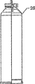
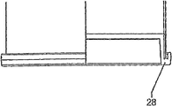
용기 패키징(26)은, 먼저 예비 성형체 사출 성형, 그런 다음 병을 형성하도록 팽창에 의한 예비 성형체의 블로잉, 그 후 이를 절단하는 3-단계 공정에 따라서 제조된다는 점에서 주목할만 하다. 용기는 접착 또는 용접에 의해 용기에 부착되는 풀 커버(28)에 의해 아래에서 폐쇄된다.The
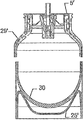
용기 패키징(29)은 PET 재료로 만들어지고, 내부 용기(30)는 상기 절단에 의해 만들어진 외부 용기(29) 아래에 있는 개구를 통해 삽입된다. 내부 용기(30)는 반드시 외부 용기(29)와 동일한 재료로 만들어지지 않으며, 반드시 원통형이지 않는 형상을 가질 수 있다. 외부 용기(29)의 하부 개구는 접착 또는 용접에 의해 용기에 부착되는 베이스 컵(25')을 통해 폐쇄된다. 내부 용기(30)는 밸브(5')에 의해 상부에서 폐쇄된다. 내부 용기(30)의 벽은 외부 용기에 의해 보다 높은 압력으로 지지되며, 그 결과, 용기 패키징은 보다 높은 압력, 예를 들어 20 bar까지 저항한다. The
용기 패키징(29')은 외부 용기(29)의 변형이며, 밸브(5')는 용기 패키징 내로 통합되고, 그러므로 외부로부터 격리되고 외부 용기(29')의 내벽을 통하여 밸브를 홀딩하기 위한 추가의 안전성으로서 더이상 제거 가능하지 않다. The
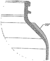
용기 패키징(29")은 외부 용기가 상부 및 저부에서 2번 절단되는 것에서 주목할만한 외부 용기(29)의 추가의 변형이다. The
용기 패키징(30)은 하나의 단부 개구를 가지며, 즉 그 저부에서 절단되지 않고, 플라스틱, 특히 변성 PET로 이루어져서, 보다 높은 압력에 저항하는 점에서 주목할만 하다. The
대기압 패키징 및/또는 압력 패키징의 경우에, 용기는 폐쇄 커버베이스(18)로 폐쇄될 수 있고, 상기된 방법에 따라서 또는 압축되거나 또는 압축되지 않을 수 있다. 이것한 것은 1-챔버 시스템으로 지칭된다.In the case of atmospheric packaging and / or pressure packaging, the container may be closed with a
도 22는 상기된 다양한 각종 방법에 따라서 용기가 아래에서 폐쇄되는 2-챔버 시스템을 도시하고, 2개의 챔버는 용기에 챔버 파티션(19)을 끼우는 것에 의해 얻어진다. 챔버 파티션(19)은 압력 제어 밸브(20)를 구비하거나 또는 구비하지 않을 수 있지만, 이러한 압력 제어 밸브(20)는 예를 들어 외부로부터 또한 개방될 수 있는 클로저일 수 있어서, 챔버(21)의 내용물은 챔버(22)와 접촉할 수 있다. 챔버들은 압력 하에 있거나 또는 그러하지 않을 수 있다.Figure 22 illustrates a two-chamber system in which the vessel is closed from below in accordance with various of the various methods described above, and two chambers are obtained by sandwiching the
상기의 본 발명에 따른 3-챔버 또는 다중 챔버 시스템(도시되지 않음)에서, 하나 이상의 챔버(19) 및 파티션(19')이 끼워진다. 단지 챔버 파티션(19')만이 끼워지면, 제3 챔버(23)가 얻어진다. 챔버 파티션은 압력 제어 밸브(20), 또는 예를 들어 챔버(21)의 내용물이 챔버(22)와 접촉하도록 외부로부터 개방될 수 있는 클로저를 구비할 수 있다. 챔버들은 압력 하에 있거나 또는 그러하지 않을 수 있다.In the three-chamber or multi-chamber system (not shown) according to the invention, one or
다수의 챔버는 상이한 챔버 파티션을 끼우는 것에 의해 생성될 수 있다. 상이한 챔버에서, 충전 제품은 액체, 분말 또는 가스로 이루어질 수 있다. 챔버는 압력 하에 있거나 또는 그러하지 않을 수 있다. 그러므로, 압력 패키징은 적어도 2개의 챔버로 이루어진 다중 챔버 시스템에 의해 형성될 수 있으며, 2-챔버 시스템의 경우에, 아래에 있는 챔버는 특정된 것으로서 폐쇄되고, 챔버 파티션은 용기에서 상이한 챔버를 생성하기 위하여 끼워진다. 이러한 경우에, 챔버 파티션은 적어도 하나의 압력 제어 밸브 또는 가스 처리 밸브를 구비할 수 있다. 특히, 이러한 압력 제어 밸브는, 하나의 챔버의 내용물이 다른 챔버와 접촉할 수 있도록 압력 제어 밸브에 의해 외부로부터 간접적으로 개방될 수 있는 클로저일 수 있으며, 챔버들은 압축되거나 또는 압축되지 않을 수 있으며, 가능하게, 베이스 및 상부측 모두는 동일한 폐쇄부, 즉 클로저에 의해 폐쇄되고, 특히 이러한 커버는 도우징 밸브, 또는 가능하게 스크루 캡, 또는 다른 클로저로 이루어진다.Multiple chambers may be created by sandwiching different chamber partitions. In a different chamber, the filling product may be composed of liquid, powder or gas. The chamber may or may not be under pressure. Thus, the pressure packaging may be formed by a multi-chamber system of at least two chambers, in the case of a two-chamber system, the underlying chamber is closed as specified, and the chamber partition creates a different chamber in the vessel To be inserted. In this case, the chamber partitions may have at least one pressure control valve or gas treatment valve. In particular, such a pressure control valve may be a closure that can be opened indirectly from the outside by a pressure control valve such that the contents of one chamber may be in contact with another chamber, the chambers may be compressed or uncompressed, Possibly, both the base and the upper side are closed by the same closure, i.e. a closure, and in particular such a cover consists of a dosing valve, or possibly a screw cap, or other closure.
본 발명은 또한 1-단계 또는 2-단계 공정(1)에 의해 형성된 플라스틱, 예를 들어 PET로 만들어진 용기, 또는 튜브를 얻기 위하여 용기의 절단에 의해 따르게 되는 1-단계 또는 2-단계 공정에 의해 형성된 용기로 이루어진 압력 패키징 다중 챔버 시스템에 관한 것이다. 어느 하나의 용기(1')는 압출 공정에 의해 형성된다. The invention also relates to a process for the preparation of a plastic, for example a PET made by a one- or two-step process (1), or a one- or two-step process followed by cutting of the container to obtain a tube To a pressure packaging multi-chamber system comprised of a formed vessel. One of the containers 1 'is formed by an extrusion process.
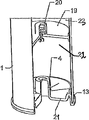
용기는 조인트(13)에 의해 용기(1)에 부착되는 베이스(2)에 의해 아래에서 폐쇄된다. 조인트(13)는, 예를 들어, 접착, 봉합 또는 용접에 의해 얻어질 수 있다. 또는 용기는 폐쇄 커버 베이스(18)에 의해 아래에서 폐쇄되는 것이다. The container is closed at the bottom by a base (2) which is attached to the container (1) by a joint (13). The joint 13 can be obtained, for example, by gluing, sealing or welding. Or the container is closed from below by the
상부에서, 용기(1)는 커버(5)에 의해 위에서 폐쇄되며, 이러한 커버는 도우징 밸브(17) 또는 스크루 캡 또는 다른 클로저일 수 있다.At the top, the
용기(1)가 압출 공정에 의해 제조되면, 상부 측은 조인트(12)에 의해 용기(1)에 부착되는 용기 헤드(11)로 폐쇄된다. 조인트(12)는 예를 들어 접착, 봉합 또는 용접에 의해 얻어질 수 있다. When the
용기 헤드(11)는 차례로 커버(5)로 폐쇄될 수 있으며, 커버는 도우징 밸브(17) 또는 스크루 캡 또는 다른 클로저일 수 있다.The
액체, 반죽, 크림 등과 같은 충전 제품이 외벽 및 고압 가스(가스, 공기 등)와 접촉하는 것을 방지하기 위하여, 가요성 내부 용기(16)는 예를 들어 블로잉에 의해 용기 내로 삽입된다. The flexible
또한, 본 발명은 또한 용기의 패키징, 특히 상기에서 정의된 바와 같은 압축 용기를 제조하는 방법에 관한 것이며, 본 발명에서 사용된 용기는 튜브를 얻기 위하여 용기의 절단이 이어지는 1-단계 공정에 의해 형성되며, 압력 수단은 충전 제품을 패키징하는 용기를 특히 가스 처리에 의해 대기압으로부터 대략 100 bar까지 압축하도록 용기에 배열된다. The present invention also relates to the packaging of containers, in particular to a method of producing compressed containers as defined above, wherein the containers used in the present invention are formed by a one-step process followed by cutting of the containers to obtain tubes And the pressure means is arranged in the vessel to compress the container for packaging the packed product, in particular by gas treatment, from atmospheric pressure to about 100 bar.
용기는 1-단계 공정 대신에 2-단계 공정에 의해 또한 형성될 수 있으며, 가능하게 본 발명에서 사용되는 용기는 절단없이 사출 성형에 의해 직접 형성될 수 있다. 압축은 밀봉구에 의해 자기 폐쇄 가능한 개구를 통해 폐쇄 가능한 하부 밸브를 통해 행해질 수 있으며, 이러한 밀봉구는 가요성 플라스틱으로 만들어진 튜브 요소로 이루어지고; 특히 본 발명에서 압축은 폐쇄 가능한 상부 밸브를 통해 일어난다. The container may also be formed by a two-step process instead of the one-step process, and possibly the container used in the present invention may be formed directly by injection molding without cutting. Compression can be done through a self-closing opening by means of a seal and through a closeable lower valve, said seal comprising a tube element made of flexible plastic; Particularly in the present invention, the compression takes place via the closable upper valve.
압력 용기 패키징을 제조하기 위한 특정 방법에 따라서, 압력 용기 패키징은 압출 공정에 의해 형성된 용기에 의해, 또는 적어도 한번, 특히 두번 절단되는 압출 튜브에 의해 형성되며, 결과적인 몸체의 두 개방 단부는 동일편, 클로저 또는 커버에 의해 폐쇄되고; 특히 상부 가장자리는 조인트에 의해 용기에 부착되는 용기 헤드로 폐쇄되며, 더욱 특히 용기 헤드는 차례로 커버로 폐쇄되고, 이러한 커버는 도우징 밸브, 또는 스크루 캡 또는 다른 클로저이다. According to a particular method for producing pressure vessel packaging, the pressure vessel packaging is formed by a container formed by an extrusion process, or by an extruded tube which is cut at least once, in particular twice, and the two open ends of the resulting body , Closed by a closure or cover; In particular, the top edge is closed with a container head which is attached to the container by means of a joint, more particularly the container head is in turn closed with a cover, which is a dosing valve, or a screw cap or other closure.
요약하면, 본 발명의 압력 용기(1)에 통합되는 주요 초석은 물리적인 보강재, 특히 포일, 보강 링 및/또는 리브, 내부 및/또는 외부 슬롯이며; 및/또는 화학적인 보강재, 특히 결정화도, 유리 전이 온도, PEN의 사용을 포함하고 결정화도를 증가시키는 폴리머 블렌드; 및/또는 특히 블렌드, 내부 코팅을 포함하는 코팅의 수단에 의한 화학적 저항; 및/또는 특별한 구조 형태, 특히 보강재, '병에 있는 백', 1-챔버 또는 2-챔버 시스템, 또는 '베이스 컵을 구비한 구형 베이스'이다. In summary, the main cornerstone incorporated in the
Claims (66)
상기 상부 섹션 반대편에 배치된 상기 저부 섹션(21)은, 조인트(13)에 의해 상기 몸체(22)에 부착되는 별도의 추가 바닥부(21)에 의해 폐쇄되고, 상기 몸체(22)는 보강재(30) 세트를 구비하는 것을 특징으로 하는 용기.A container for packaging under pressure a respective continuous discontinuous filling product, such as a liquid or semi-liquid, or each discontinuous filling product such as a foam, dough, cream, or powder, having a neck section 23 ), An adjacent shell section (22) forming the body of the container, and a bottom section (21) of the container, essentially consisting of a plastic polymer and closable by a closure (5) As a result,
The bottom section 21 disposed on the opposite side of the upper section is closed by a separate additional bottom 21 attached to the body 22 by a joint 13, 30). ≪ / RTI >
상기 용기(1) 내에 완전히 포함되고 상기 용기(1)가 받는 압력(p1)과 다른 자체 압력(p2)을 받는 내부 용기(2)를 포함하며, p2 > p1이며, 적어도 p2 > 대기압이며, 상기 내부 용기(2)의 높은 압력과 상기 용기(1)의 낮은 압력 사이의 차압인 상기 내부 용기(2)의 잔류 압력을 산출하는 것을 특징으로 하는 용기.The method according to claim 1,
The container is fully contained in the (1) an internal container (2) receiving the container (1) the pressure (p 1) and the other self-pressure (p 2) receiving, p 2 > p 1 , and at least p 2 Wherein the internal pressure of the inner vessel (2) is atmospheric pressure and is a pressure difference between the high pressure of the inner vessel (2) and the low pressure of the vessel (1).
상기 용기(1) 내부에는 내부 압력 p2 인 내부 용기(2)가 제공되며, 상기 내부 용기는 압력 p1 하에 있는 상기 용기(1) 내에 완전히 포함되고 상기 용기(1)의 베이스(21)에 부착되어 이중 용기 시스템(12)을 형성하며, 상기 내부 용기(2)는 상기 용기(1)에 의해 추가적으로 지지되는 것을 특징으로 하는 용기.A container for packaging under pressure a respective continuous discontinuous filling product, such as a continuous filling product comprising a fluid, or a foam, cream, or powder, comprising a neck portion (23) having an injection opening (24) A sleeve portion (22) adjacent the neck portion and forming a body of the container, and a base portion (21), wherein the container is essentially comprised of a plastic polymer,
An internal vessel 2 with an internal pressure p 2 is provided inside the vessel 1 and the internal vessel is completely contained in the vessel 1 under a pressure p 1 and in the base 21 of the vessel 1 (2) is additionally supported by said container (1). ≪ RTI ID = 0.0 > 11. < / RTI >
상기 내부 용기(2)는 상기 용기(1)가 받는 압력(p1)과 다른 자체 압력(p2)을 받고, 상기 내부 용기(2)는 상기 용기(1)보다 높은 압력 하에 있으며, 적어도 상기 압력 p2는 대기압보다 높고, 상기 내부 용기(2) 상의 잔류 압력(Δp)은 상기 내부 용기(2)의 높은 압력과 상기 용기(1)의 낮은 압력 사이의 양의 차이값과 같은 것을 특징으로 하는 용기.The method of claim 3,
It said inner container (2) is the pressure (p 1) and the other self-pressure (p 2) receiving the inner container (2) when the container (1) receives is under higher pressure than the vessel (1), at least the the pressure p 2 is higher than atmospheric pressure, the residual pressure (Δp) on the inside of the container (2) is characterized as positive difference value between the lower pressure of the high pressure and the container (1) of the inner container (2) The courage to.
상기 내부 용기(2)는 상기 용기(1)보다 얇은 벽 두께로서 상기 내부 용기(2)의 압력 p2 특성을 견디는 벽 두께를 가지며, 상기 이중 용기 시스템(12)은 내부 보상 압력을 가진 버퍼로서 작용하는 것을 특징으로 하는 용기.5. The method according to any one of claims 2 to 4,
Said inner container (2) is a buffer with the double container system 12 is internally compensated pressure has a wall thickness to withstand the pressure p 2 properties of the inner container (2), a thin wall thickness than that of the container (1) ≪ / RTI >
상기 이중 용기 시스템(12)은 압력 조정기, 특히 PCD형의 압력 조정기를 구성하는 것을 특징으로 하는 용기.6. The method according to any one of claims 3 to 5,
Characterized in that the dual-container system (12) constitutes a pressure regulator, in particular a pressure regulator of the PCD type.
최대 약 20 bar, 특히 최대 100 bar 까지 견딜 수 있는 압력 하의 패키징을 특징으로 하는 용기. 7. The method according to any one of claims 1 to 6,
A container characterized by a pressure-resistant packaging capable of withstanding up to about 20 bar, in particular up to 100 bar.
물리적 또는 기계적 보강재(30; 31, 32; 8'; 9, 9'; 10') 세트를 구비하는 것을 특징으로 하는 용기.8. The method according to any one of claims 1 to 7,
Characterized in that it comprises a set of mechanical or mechanical stiffeners (30; 31, 32; 8 '; 9, 9'; 10 ').
상기 보강재는 연결부에 의해 상기 바닥부(21)에 부착되는 내부 용기(2)에 의해 형성되고, 상기 용기(1)는 상기 내부 압력 p2 상태 하에 있는 내부 용기(2)에 추가적인 지지를 제공하는 것을 특징으로 하는 용기.9. The method of claim 8,
The reinforcement is formed by an inner container (2) is attached to the bottom portion 21 by a connecting portion, the container 1 is to provide additional support to the inner container (2) under the condition that the internal pressure p 2 ≪ / RTI >
압력 용기(1 또는 1')의 내부 및/또는 외부 측에서 상호 거리 d1에 보강 요소 세트(31, 32)가 제공되는 것을 특징으로 하는 용기.10. The method according to claim 8 or 9,
Characterized in that a set of reinforcing elements (31, 32) is provided at a mutual distance d 1 on the inside and / or the outside of the pressure vessel (1 or 1 ').
상기 보강 요소(31, 32)는 가장자리에, 특히 실질적으로 일정한 단면으로, 특히 회전 대칭 프로파일로 제공되는 것을 특징으로 하는 용기.11. The method according to any one of claims 8 to 10,
Characterized in that the reinforcing elements (31, 32) are provided at the edges, in particular with a substantially constant cross-section, in particular with a rotationally symmetrical profile.
상기 보강 요소(31, 32)는 둥근 프로파일로, 특히 외향으로 배향된 상부를 가진 실질적으로 반원형 단면을 가지는 것을 특징으로 하는 용기. 12. The method of claim 11,
Characterized in that the reinforcing elements (31, 32) have a substantially semicircular cross-section with a rounded profile, in particular with an outwardly directed top.
상호 인접한 보강 요소들(31, 32) 사이의 상기 거리 d1은 종방향 몸체 단부로부터 몸체(22)의 종방향 중간 섹션으로 갈수록 감소하며, 특히 중간 섹션에 대해 균일하게 감소하는 것을 특징으로 하는 용기.13. The method according to any one of claims 10 to 12,
Mutually adjacent reinforcing elements of the distance d 1 between 31 and 32 and decreasing in the longitudinal direction middle section of the body 22 from the longitudinal body end, in particular the container, characterized in that to uniformly decrease with respect to the intermediate section .
홀수의 보강 요소, 특히 링(31, 32)이 제공되고, 중간 보강 요소가 상기 중간 섹션 둘레에 배치되는 것을 특징으로 하는 용기.14. The method of claim 13,
Characterized in that an odd number of reinforcing elements, in particular rings (31, 32), are provided and an intermediate reinforcing element is arranged around said middle section.
상기 보강 요소(32)는 두꺼운 부분, 또는 보강 리브(9)의 세트로 구성되며, 특히 압력 용기(1)의 재료와 직접 일 부품(9')으로 일체로 형성되는 것을 특징으로 하는 용기.15. The method according to any one of claims 10 to 14,
Characterized in that the reinforcing element (32) consists of a thicker part, or a set of reinforcing ribs (9), in particular integrally formed by a part (9 ') directly with the material of the pressure vessel (1).
상기 보강 요소(31)는 상기 압력 용기(1)와 연결되는 일 세트의 내부 지지링(31 및 8'), 및/또는 일 세트의 외부 지지링(32 및 10')으로 이루어지는 것을 특징으로 하는 용기. 16. The method according to any one of claims 10 to 15,
Characterized in that the reinforcing element (31) comprises a set of inner support rings (31 and 8 ') connected to the pressure vessel (1) and / or a set of outer support rings (32 and 10') Vessel.
상기 보강 링은 각각 접착 또는 용접 재료에 의해 상기 용기(1)와 연결되는 것을 특징으로 하는 용기. 17. The method of claim 16,
Characterized in that the reinforcing ring is connected to the container (1) by adhesive or welding material, respectively.
상기 보강 링은 각각 재료 링크 없이, 특히 클램핑 또는 수축 등에 의해 기계적으로 상기 용기(1)와 견고하게 연결되는 것을 특징으로 하는 용기. 17. The method of claim 16,
Characterized in that said reinforcing rings are each mechanically connected rigidly to said container (1) without a material link, in particular by clamping or shrinking.
상기 보강 요소(32)는, 상기 용기(1) 둘레의 수축된 포일, 메쉬 및/또는 그리드 및/또는 수축 필름으로 이루어지고, 상기 그리드는 통합되는 것을 특징으로 하는 용기. 19. The method of claim 18,
Characterized in that the reinforcing element (32) consists of a shrunk foil, mesh and / or grid and / or shrink film around the container (1), and the grid is integrated.
상기 보강 요소는, 특히 유리 섬유, 복합재, 또는 유리선으로 이루어진 용기 벽(22) 둘레의 권선으로 이루어지는 것을 특징으로 하는 용기. 20. The method according to claim 18 or 19,
Characterized in that said reinforcing element comprises a winding around a container wall (22), in particular made of glass fibers, composites or glass wires.
상기 내부 지지 링(31)은 플라스틱으로 구성되고 및/또는 상기 외부 지지 링(32)은 플라스틱 및/또는 금속으로 이루어지는 것을 특징으로 하는 용기. 21. The method according to any one of claims 10 to 20,
Characterized in that the inner support ring (31) is made of plastic and / or the outer support ring (32) is made of plastic and / or metal.
특히 상기 용기(1)의 용기 벽(22)에 있는 화학적 보강재를 포함하는 것을 특징으로 하는 용기. 22. The method according to any one of claims 10 to 21,
In particular a chemical reinforcement in the vessel wall (22) of the vessel (1).
특히 용기 몸체 벽에서, 특히 적어도 일 부분에서, 투명한 것을 특징으로 하는 용기. 23. The method according to any one of claims 1 to 22,
In particular in the container body wall, in particular in at least one part.
용기를 만드는 상기 플라스틱 재료는 2축 신축성 재료, 특히 PET(폴리에틸렌 테레프탈레이트)로 이루어지는 것을 특징으로 하는 용기. 24. The method according to any one of claims 1 to 23,
Wherein the plastic material for making the container is made of biaxial stretchable material, in particular PET (polyethylene terephthalate).
특히 목 섹션(23)이 바닥부에 단부 개구를 구비하고 바닥부에서 절단되지 않으면, 보다 높은 압력 및/또는 온도에 저항하도록, 합성 재료, 특히 변성 PET로 이루어지는 것을 특징으로 하는 용기. 25. The method according to any one of claims 1 to 24,
Characterized in that the neck section (23) is made of synthetic material, in particular modified PET, so as to withstand higher pressures and / or temperatures if the neck section (23) is provided with an end opening in the bottom and is not cut at the bottom.
상기 용기(1)는 플라스틱 재료로 사출성형 예비 성형체의 스트레칭 및 블로잉에 의해 구성되고, 상기 예비 성형체는 보다 높은 열치수 안정성을 갖도록 높은 결정화도를 가지며, 상기 결정화도는 배향 유도 결정화도를 형성하며, 특히 결정화도는 30% 초과, 특히 35 내지 40%인 것을 특징으로 하는 용기. 25. The method according to any one of claims 1 to 24,
The container (1) is constituted by stretching and blowing of an injection-molded preform with a plastic material, and the preform has a high degree of crystallinity so as to have higher thermal dimensional stability, the degree of crystallization forms an orientation-induced crystallinity, Is greater than 30%, especially 35 to 40%.
상기 용기는 다른 플라스틱 재료, 특히 폴리올레핀, 특히 폴리프로필렌 또는 폴리에틸렌, 폴리스티렌, 폴리에스테르, 특히 PETG 또는 PBT, 폴리카보네이트, 폴리아미드, 또는 그 공중합체 또는 그 블렌드, 특히 극히 낮은 레벨에 따라서 보다 높은 열에 대해 저항하는 다른 폴리에스테르를 가진 공중합체로 만들어지고, 특히, 상기 폴리에스테르는 폴리에틸렌 나프탈레이트; 폴리트리메틸렌 나프탈레이트에 의해; 또는 PETN-5형 400105로서 공지된 플라스틱 재료에 의해 형성되는 것을 특징으로 하는 용기. 27. The method of claim 26,
The container may be made of other plastic materials, especially polyolefins, especially polypropylene or polyethylene, polystyrene, polyester, especially PETG or PBT, polycarbonate, polyamide or a copolymer or blend thereof, Resistant polyester, and in particular, the polyester is selected from the group consisting of polyethylene naphthalate; By polytrimethylene naphthalate; Or PETN-5 type 400105. < Desc / Clms Page number 13 >
상기 플라스틱은, 특히 배리어의 통합, 특히 화학적, 또는 가스 또는 광 배리어의 통합을 갖는 소위 '폴리머 바이오 집합체'로 이루어지는 것을 특징으로 하는 용기. 28. The method according to any one of claims 1 to 27,
The plastic is characterized in that it consists, in particular, of a so-called " polymer bio-assembly " with integration of the barrier, in particular chemical or gas or light barrier integration.
상기 용기(1)가 제조되는 예비 성형체는, 열 수축이 작업 온도의 사전 결정된 설정값에서 특정 설정값을 초과하지 않는 정도의 열 특성을 가지며, 특히 상기 수축 설정값은 4% 내지 5% 초과하지 않도록, 특히 3.5% 이하, 바람직하게 1% 이하인 것을 특징으로 하는 용기. 1. A container for receiving radiation sensitive products such as photosensitive and / or gas sensitive products, in particular foods, cosmetics, detergents and the like, comprising at least one base layer (11) of base plastic base material (11) 1)
The preform in which the container (1) is manufactured has a thermal characteristic to such an extent that the heat shrinkage does not exceed a specific set value at a predetermined set value of the working temperature, and in particular, the shrinkage setting value is not more than 4% to 5% , In particular not more than 3.5%, preferably not more than 1%.
상기 첨가제는 PET 첨가제로 이루어지는 것을 특징으로 하는 용기. 30. The method of claim 29,
Wherein said additive comprises a PET additive.
상기 예비 성형체(20)는 단층 구조를 가지는 것을 특징으로 하는 용기. 32. The method according to claim 29 or 30,
Wherein the preform (20) has a single layer structure.
상기 용기(1)는 다층 구조를 가지며, 특히 배리어 층, 특히 2차 플라스틱 재료로 구성되어 사실상 모든 전송된 광 및/또는 산소가 차단될 수 있는 광 및/또는 산소 배리어로서 작용하는 중간층이 포함되는 상기 기본 베이스 층으로 이루어진 3-층 구조를 가지는 것을 특징으로 하는 용기. 32. The method according to any one of claims 29 to 31,
The container 1 has a multilayer structure, in particular a barrier layer, in particular an intermediate layer which is composed of a secondary plastic material and which acts as light and / or oxygen barrier in which virtually all transmitted light and / or oxygen can be blocked Wherein the base layer has a three-layer structure consisting of the basic base layer.
상기 용기는 특히 아크릴레이트로 내부 및/또는 외부가 코팅되는 것을 특징으로 하는 용기. 33. The method according to any one of claims 1 to 32,
Characterized in that the container is coated internally and / or externally, in particular with acrylate.
상기 용기(1)는 고정 연결부에 의해 상기 용기에 고정적으로 부착되는 풀 커버(28)에 의해 바닥부 측에서 폐쇄되는 것을 특징으로 하는 용기. 34. The method according to any one of claims 1 to 33,
Wherein the container (1) is closed at the bottom side by a pull cover (28) fixedly attached to the container by a fixed connection.
복합체는 용접된 조인트(13), 특히 레이저, 유도, 초음파 복합체, 또는 접착 조인트에 의해 형성되는 것을 특징으로 하는 용기. 35. The method of claim 34,
Characterized in that the composite is formed by a welded joint (13), in particular a laser, induction, ultrasonic composite, or adhesive joint.
상기 용기(1)는 보다 높은 압력을 허용하기 위하여 반구형 프로파일을 갖는 바닥부(21)를 구비하고, 바닥부 홀더(25)가 제공되는 것을 특징으로 하는 용기. 6. The method according to any one of claims 1 to 5,
Characterized in that the container (1) is provided with a bottom part (21) having a hemispherical profile to allow a higher pressure and a bottom part holder (25) is provided.
추가된 베이스(21')에 밸브가 포함되는 것을 특징으로 하는 용기. 37. The method according to any one of claims 1 to 36,
Characterized in that a valve is included in the added base (21 ').
상기 용기(1)는 적어도 하나의 챔버(51), 특히 두 개의 챔버(52)로 이루어진 다중 챔버 시스템으로 형성되며, 상기 압력 용기(1)는 바닥부에서 폐쇄되고, 상기 용기의 챔버들 사이에는 챔버 파티션(59)이 제공되는 것을 특징으로 하는 용기. 37. The method according to any one of claims 1 to 37,
The container 1 is formed of a multi-chamber system consisting of at least one chamber 51, in particular two chambers 52, the pressure vessel 1 being closed at the bottom and between the chambers of the vessel A chamber partition (59) is provided.
상기 챔버 파티션(59)은 클로저로서 적어도 하나의 압력 제어 밸브(50), 또는 가스 밸브를 구비하는 것을 특징으로 하는 용기. 39. The method of claim 38,
Characterized in that the chamber partitions (59) comprise at least one pressure control valve (50), or a gas valve, as a closure.
상기 클로저는 압력 제어 밸브(50)에 의해 개방 또는 폐쇄 위치에서 외부로부터 간접적으로 조정 가능하여서, 상기 챔버(51)의 내용물은 챔버가 압력하에 있든지 없든지 상관없이 챔버(52)와 접촉할 수 있는 것을 특징으로 하는 용기. 40. The method of claim 39,
The closure is indirectly adjustable from the outside in the open or closed position by means of the pressure control valve 50 so that the contents of the chamber 51 can be in contact with the chamber 52 whether the chamber is under pressure or not Lt; / RTI > container.
상기 저부측 및 상부측(21 및 23)은 단일 폐쇄 부품, 특히 차단 밸브(58)에 의해 폐쇄되는 것을 특징으로 하는 용기. 41. The method of claim 40,
Characterized in that the bottom and upper sides (21 and 23) are closed by a single closing part, in particular a shut-off valve (58).
상기 차단 밸브(58)는 도우징 밸브(57) 또는 스크루 캡으로 형성되는 것을 특징으로 하는 용기. 42. The method of claim 41,
Characterized in that the shut-off valve (58) is formed by a dosing valve (57) or a screw cap.
상기 용기는 물리적 보강재, 특히 포일, 보강 링 및/또는 리브, 내부 및/또는 외부 슬롯; 및/또는 특히 증가된 결정화도, 유리 전이 온도의 화학적 보강재, PEN의 사용을 포함하고 결정화도를 증가시키는 폴리머 블렌드; 및/또는 특히 블렌드, 내부 코팅을 포함하는 코팅에 의한 화학적 저항재; 및/또는 특별한 형태, 특히 보강재로서 '병 내부의 병', '병 내부의 백', 1-챔버 또는 2-챔버 시스템, 또는 '베이스 컵을 가진 구형 베이스' 등의 구조형의 압축 용기를 포함하는 것을 특징으로 하는 용기. 43. The method according to any one of claims 1 to 42,
The container may comprise a physical stiffener, in particular a foil, a reinforcing ring and / or rib, an inner and / or outer slot; And / or polymer blends that include increased crystallinity, chemical reinforcements of glass transition temperature, use of PEN and increase crystallinity; And / or chemical resistance materials by coating, especially including blends, inner coatings; Chambered or two-chamber system, or a 'spherical base with a base cup', in particular in the form of a container, ≪ / RTI >
종방향 축(ℓ)을 갖는 용기 몸체 프로파일(90)을 먼저 형성하고, 요구되는 종방향 치수(L)로 튜브 요소(91)를 형성하도록 상기 몸체 프로파일(90)을 절단하며, 압력 수단이 충전 제품을 가진 용기 패키징(1)을 가스에 의해 대기압으로부터 대략 100 bar의 범위 내의 압력 p1으로 압축하도록 배열되며, 상기 용기 패키징(1)은 압출 공정에 의해 형성된 용기 몸체(91)에 의해 형성되고, 특히 용기 헤드(11) 또는 몸체 상부 섹션(22')은 커버(5)로 폐쇄되고, 특히 상기 커버는 도우징 밸브(17), 스크루 캡 또는 다른 클로저인 것을 특징으로 하는 용기 제조 방법.43. A method of manufacturing a container in the form of a pressure vessel packaging according to any one of claims 1 to 43,
The body profile 90 having the longitudinal axis l is first formed and the body profile 90 is cut to form the tube element 91 with the required longitudinal dimension L, The container packaging 1 is arranged to be compressed by the gas at atmospheric pressure to a pressure p 1 in the range of about 100 bar, the container packaging 1 being formed by a container body 91 formed by an extrusion process , In particular the container head (11) or the body upper section (22 ') is closed with a cover (5), in particular the cover is a dosing valve (17), a screw cap or other closure.
상기 상부 섹션은 압축된 용기(1)에 대한 연결부(12)에 의해 고정되는 용기 헤드(11)로 밀폐되는 것을 특징으로 하는 용기 제조 방법.46. The method according to claim 44 or 45,
Characterized in that the upper section is sealed with a container head (11) which is fixed by a connection (12) to a compressed container (1).
상기 연결부(12)는 접착, 크림핑 또는 용접, 특히 레이저 용접, 특히 레이저, 유도 또는 초음파 용접에 의해 형성되는 것을 특징으로 하는 용기 제조 방법.55. The method according to any one of claims 44 to 53,
Characterized in that the connection (12) is formed by gluing, crimping or welding, in particular by laser welding, in particular by laser, inductive or ultrasonic welding.
링들의 고정부는 서로 접착 또는 용접되는 것을 특징으로 하는 용기 제조 방법.47. The method of claim 46,
Wherein the fixing portions of the rings are bonded or welded to each other.
상기 외부 지지링(10)은 상기 용기를 블로잉할 때 직접 통합되는 것을 특징으로 하는 용기 제조 방법.49. The method according to any one of claims 44 to 48,
Wherein the outer support ring (10) is directly integrated when blowing the container.
충전 제품이 외벽 및, 공기 또는 다른 가스로 이루어진 압축 가스와 접촉하는 것을 방지하기 위하여, 상기 용기 내에 가요성 내부 용기(16) 또는 백이 삽입되는 것을 특징으로 하는 용기 제조 방법.A method according to any one of claims 44 to 49,
Characterized in that a flexible inner container (16) or bag is inserted in the container to prevent the filling product from contacting the outer wall and a compressed gas comprising air or other gas.
상기 가요성 내부 용기(16)는 주 용기로서 작용하는 상기 용기(1) 내에 블로잉에 의해 통합되는 것을 특징으로 하는 용기 제조 방법.51. The method of claim 50,
Characterized in that the flexible inner container (16) is integrated by blowing into the container (1) acting as a main container.
상기 압축 용기의 제조 공정은,
제1 단계(A)에서, 예비 성형체가 사출 성형에 의해 반완성 제품으로서 압출되고, 플라스틱 과립이 압출기에서 건조되고 용융되며, 이어서 사출 몰드에서 구동되며;
이어지는 단계(B)에서, 상기 반완성 제품이 추가 중간 제품(3)으로서 병 형상, 특히 관형체(3)로 블로잉 몰드에서 블로잉되며;
추가의 다음 단계(C)에서, 상기 추가 중간 제품(3)의 저부 사이가 특정 길이로 절단되고, 별도의 추가 사출 성형 베이스(21)가 상기 추가 중간 제품(3)에 통합되는 것에 의해 실행되는 것을 특징으로 하는 용기 제조 방법.45. A method according to any one of claims 44 to 51 for producing a compressed-container packaging according to any one of claims 1 to 43,
The manufacturing process of the compression vessel includes:
In a first step (A), the preform is extruded as a semi-finished product by injection molding, the plastic granules are dried and melted in an extruder and then driven in an injection mold;
In a subsequent step (B), the semi-finished product is blown in a bottle mold, in particular as a further intermediate product (3), in a blowing mold with a tubular body (3);
In a further subsequent step (C), the bottom part of the additional intermediate product (3) is cut to a certain length and a further additional injection molding base (21) is carried out by being incorporated into the additional intermediate product ≪ / RTI >
상기 용기(1) 내에 충전 제품의 압축은, 밀봉구(44)에 의해 자기 폐쇄 가능한 개구(43)를 통해 록킹 가능한 저부 밸브를 통해 실행되며, 상기 밀봉구(44)는 가요성 플라스틱으로 제조되는 관형 요소로 이루어지는 것을 특징으로 하는 용기 제조 방법.53. The method of claim 52,
The compression of the filling product in the container 1 is carried out through a sealable opening 44 through a self-closable opening 43 and the seal 44 is made of flexible plastic Wherein the tubular element comprises a tubular element.
상기 용기(1) 내의 압축은 밀봉 가능한 상부 밸브(47)를 통해, 특히 자기 록킹 요소, 특히 소위 "엄브렐러 플러그(46)", 또는 2-단계 요소, 특히 소위 "니콜슨 플러그(47)"를 통해 실행되는 것을 특징으로 하는 용기 제조 방법.54. The method of claim 53,
The compression in the container 1 is carried out via the sealable upper valve 47, in particular via a self-locking element, in particular the so-called "umbrella plug 46," Is performed.
상기 예비 성형체는 사출 가능한 기본 플라스틱 재료(11)에 특정 비율의 첨가제(12)를 추가하고, 소위 유리 전이 온도값(Tg)을 증가시키기 위해 소위 블렌드(13)를 형성하며, 상기 블렌드(13)는 상기 예비 성형체를 생성하도록 사출되고, 그런 다음 외부 방사선 및 가스, 특히 전자기 방사선, 특히 광에 대해 내부(9)를 보호하기 위하여, 상기 방사선이 사실상 절단되도록 상기 기본 재료의 굴절율이 영향을 받는 방식으로, 상기 Tg값으로 용기로부터 송풍되는 것을 특징으로 하는 용기 제조 방법.A method for producing a container for encapsulating an article containing a dairy product in a container by injection molding of a preform by blowing the preform to a container according to any one of the preceding claims,
The preforms form a so-called blend 13 to add a certain proportion of additive 12 to the injectable base plastic material 11 and increase the so-called glass transition temperature value T g , and the blend 13 ) Is injected to produce the preform, and then, in order to protect the interior 9 against external radiation and gases, in particular electromagnetic radiation, in particular light, the refractive index of the base material is influenced Wherein the T g value is blown out of the vessel.
상기 용기의 결정화도를 증가시키기 위하여 상기 공중합체에 첨가제가 추가로 첨가되는 것을 특징으로 하는 용기 제조 방법.56. The method of claim 55,
Wherein an additive is additionally added to the copolymer to increase the crystallinity of the container.
상기 유리 전이 온도는 적어도 95℃의, 바람직하게 100℃ 이하의 목표값으로 증가되는 것을 특징으로 하는 용기 제조 방법.58. The method of claim 57,
Wherein the glass transition temperature is increased to a target value of at least 95 ° C, preferably less than or equal to 100 ° C.
폴리머 첨가제는, 상기 블렌드(13)의 상기 Tg값이 상기 기본 플라스틱 재료(11)의 값보다 높은 값으로 증가되도록 선택되는 것을 특징으로 하는 용기 제조 방법.58. The method of claim 57 or 58,
Polymer additives, a container manufacturing method is characterized in that the T g value for the blend (13) is selected to be increased to a value higher than the value of the basic plastic material (11).
상기 예비 성형체(10)는 상기 기본 베이스 재료(11)에 중화 시약 또는 중화제의 첨가에 의해 중화되어, 결정 격자를 형성하는 것을 특징으로 하는 용기 제조 방법.35. The method according to any one of claims 33 to 34,
Wherein the preform (10) is neutralized by adding a neutralizing reagent or a neutralizing agent to the base material (11) to form a crystal lattice.
상기 예비 성형체는 상기 폴리머의 결정화 효과를 발생시키도록 특정 가열 온도로 가열되고, 상기 베이스 재료의 증가된 결정화도는 적절한 시약의 작용에 의해 생기는 것을 특징으로 하는 용기 제조 방법.64. The method of claim 60,
Wherein the preform is heated to a specific heating temperature to produce a crystallizing effect of the polymer and the increased crystallinity of the base material is caused by the action of a suitable reagent.
동시 사출에 의한 다층 예비 성형체의 사출 성형 후에 용기로 예비 성형체를 블로잉하는 것을 특징으로 하는 용기 제조 방법.62. The method of claim 44 or claim 61,
Wherein the preform is blown into a container after injection molding of the multilayer preform by simultaneous injection.
용기는 상기 재료로 만들어진, 사출 성형된 예비 성형체로부터 시작되고, 상기 예비 성형체가 블로잉 작업을 위하여 가열되는 온도는 상기 더욱 고열의 폴리에스테르 부분의 유리 전이 온도보다 높고, 상기 블로잉 성형 작업은 상기 온도에 도달되자마자 수행되는 것을 특징으로 하는 용기 제조 방법.43. A process for making a container according to any one of claims 1 to 43, which is made from a PET copolymer, and a higher high temperature polyester,
Wherein the container is made from an injection molded preform made of the material and the temperature at which the preform is heated for the blowing operation is higher than the glass transition temperature of the higher temperature polyester portion, Wherein the method is performed as soon as it is reached.
상기 예비 성형체는 상기 폴리에스테르 부분의 유리 전이 온도보다 높은 온도로 가열되며, 그런 다음 스트레칭할 때 블로잉 및 사출 성형 작업에서 즉시 블로잉되는 것을 특징으로 하는 용기 제조 방법.64. The method of claim 63,
Wherein the preform is heated to a temperature above the glass transition temperature of the polyester portion and then immediately blown in a blowing and injection molding operation when stretching.
상기 온도는 약 125℃ 내지 130℃ 사이에서 설정되고, 특히 상기 예비 성형체는 125℃ 내지 130℃ 사이의 범위의 온도로 가열되며, 그런 다음 스트레칭할 때 블로잉 및 사출 성형 작업에서 즉시 블로잉되는 것을 특징으로 하는 용기 제조 방법.65. The method of claim 64,
The temperature is set between about 125 ° C and 130 ° C, and in particular the preform is heated to a temperature in the range of between 125 ° C and 130 ° C and is then immediately blown in the blowing and injection molding operations when stretching Lt; / RTI >
Applications Claiming Priority (5)
| Application Number | Priority Date | Filing Date | Title |
|---|---|---|---|
| BE2011/0705 | 2011-12-05 | ||
| BE201100705A BE1020615A5 (en) | 2011-12-05 | 2011-12-05 | CONTAINER PACKAGING FOR PACKAGING PRESSURE OF FILLED GOODS I.H.B. HALF LIQUID, AND METHOD FOR THIS. |
| BE2012/0681 | 2012-10-10 | ||
| BE2012/0681A BE1025052B1 (en) | 2012-10-10 | 2012-10-10 | CONTAINER FOR PACKAGING UNDER PRESSURE OF CONTINUOUS FILL PRODUCT, AND PRODUCTION METHOD FOR THIS |
| PCT/BE2012/000053 WO2013082680A2 (en) | 2011-12-05 | 2012-12-05 | Plastic container for packing of filling product under pressure, and method for the manufacture thereof |
Publications (1)
| Publication Number | Publication Date |
|---|---|
| KR20140100991A true KR20140100991A (en) | 2014-08-18 |
Family
ID=48463648
Family Applications (1)
| Application Number | Title | Priority Date | Filing Date |
|---|---|---|---|
| KR1020147018854A KR20140100991A (en) | 2011-12-05 | 2012-12-05 | Plastic container for packing of filling product under pressure, and method for the manufacture thereof |
Country Status (28)
| Country | Link |
|---|---|
| US (1) | US20150076164A1 (en) |
| EP (2) | EP3095731B1 (en) |
| JP (2) | JP2015500778A (en) |
| KR (1) | KR20140100991A (en) |
| AP (1) | AP3924A (en) |
| AU (1) | AU2012350168A1 (en) |
| BE (2) | BE1025871B1 (en) |
| BR (1) | BR112014013437A2 (en) |
| CA (1) | CA2854929C (en) |
| CY (1) | CY1118673T1 (en) |
| DK (2) | DK2791030T3 (en) |
| EA (1) | EA030100B1 (en) |
| ES (2) | ES2918973T3 (en) |
| HR (1) | HRP20161034T1 (en) |
| HU (2) | HUE059222T2 (en) |
| IL (1) | IL232962A0 (en) |
| LT (1) | LT2791030T (en) |
| ME (1) | ME02494B (en) |
| MX (1) | MX2014006524A (en) |
| PH (1) | PH12014501552A1 (en) |
| PL (2) | PL2791030T3 (en) |
| PT (2) | PT3095731T (en) |
| RS (1) | RS55197B1 (en) |
| SG (1) | SG11201402946XA (en) |
| SI (1) | SI2791030T1 (en) |
| SM (1) | SMT201600414B (en) |
| WO (1) | WO2013082680A2 (en) |
| ZA (1) | ZA201403371B (en) |
Cited By (2)
| Publication number | Priority date | Publication date | Assignee | Title |
|---|---|---|---|---|
| KR20160028260A (en) * | 2014-09-03 | 2016-03-11 | 현대자동차주식회사 | Pressure vessel for cng and manufacturing method thereof |
| KR20220001604A (en) * | 2020-06-30 | 2022-01-06 | (주)신광엠앤피 | Spray container with pressurized filling dispenser |
Families Citing this family (14)
| Publication number | Priority date | Publication date | Assignee | Title |
|---|---|---|---|---|
| CN104955742B (en) | 2012-11-28 | 2017-05-03 | 爱柔包装技术集团有限公司 | System and method for manufacturing pressure units |
| FR3008078B1 (en) * | 2013-07-08 | 2016-04-01 | Lablabo | DEVICE WITH RIGID CONTAINER AND FLEXIBLE CYLINDRICAL POCKET FOR PACKAGING FLUIDS. |
| FR3019803B1 (en) * | 2014-04-10 | 2016-12-23 | Fareva | AEROSOL GENERATOR OF PLASTIC MATERIAL |
| BE1022703B1 (en) * | 2015-02-10 | 2016-08-17 | CARDIFF GROUP,naamloze vennootschap | Barrel for CO2-containing drinks and their use |
| WO2017080685A1 (en) * | 2015-11-10 | 2017-05-18 | Gojara | Pressure control device, dispenser comprising said pressure control device and method of manufacturing |
| USD833885S1 (en) * | 2017-01-10 | 2018-11-20 | Karen Montileone | Container with detachable bottom and dispenser |
| BE1024253B1 (en) | 2017-04-03 | 2018-01-05 | Gojara Bvba | DISC PRESSURE CONTROL DEVICE FOR PRESSURE PACKAGING |
| US11851264B2 (en) * | 2017-04-03 | 2023-12-26 | Gojara Bvba | Disc-shaped pressure control device for pressure packaging |
| US20200171734A1 (en) * | 2017-08-11 | 2020-06-04 | Husky Injection Molding Systems Ltd. | Molded article, container and a method for printing thereon |
| BE1025483B1 (en) | 2018-02-12 | 2019-03-14 | Resilux N.V. | PRESSURE PACKAGING WITH IMPROVED FALL RESISTANCE AND BUMP RESISTANCE |
| CH715159A1 (en) * | 2018-07-09 | 2020-01-15 | Alpla Werke Alwin Lehner Gmbh & Co Kg | Plastic pressure vessel with a valve attachment for dispensing a gaseous, liquid, powdery or pasty filling material. |
| US10486892B1 (en) * | 2018-08-22 | 2019-11-26 | The Procter & Gamble Company | Packages and arrays of packages for plastic aerosol dispensers |
| CN113507803B (en) * | 2021-06-15 | 2022-03-01 | 杭州电子科技大学 | Preparation method of deep-sea pressure-resistant container with imitated siderite beetle bionic structure |
| BE1030302B1 (en) | 2022-02-25 | 2023-09-25 | Gojara Bv | 2K PLASTIC BASE FOR A SPRAY CAN WITH INTEGRATED AERATION PLUG |
Family Cites Families (32)
| Publication number | Priority date | Publication date | Assignee | Title |
|---|---|---|---|---|
| US2766072A (en) * | 1952-08-02 | 1956-10-09 | Standard Container Inc | Aerosol sprayer with a replaceable cartridge |
| BE538645A (en) * | 1954-06-09 | |||
| US3327907A (en) | 1965-06-09 | 1967-06-27 | Meyers Frederick Charles | Reinforced plastic containers for pressurized products |
| US3837527A (en) * | 1973-03-16 | 1974-09-24 | L Kutik | Reinforced aerosol container |
| US4039103A (en) * | 1974-12-18 | 1977-08-02 | Hubert Juillet | Pressurized dispensing containers |
| JPS572067Y2 (en) * | 1977-06-08 | 1982-01-13 | ||
| US4122142A (en) | 1977-08-05 | 1978-10-24 | Owens-Illinois, Inc. | Method for blow molding a reinforced plastic bottle |
| SE417592B (en) | 1978-03-13 | 1981-03-30 | Plm Ab | CONTAINER OF THERMO-PLASTIC PLASTIC MATERIAL WITH STRENGTHS INSIDE THE CONTAINER WALL, AND PROCEDURE FOR THE PREPARATION OF SUCH A CONTAINER |
| JP2598348Y2 (en) * | 1987-12-18 | 1999-08-09 | 誠一 北林 | Pressure-resistant container for aerosol injection |
| JPH02214555A (en) * | 1989-02-14 | 1990-08-27 | Toyo Seikan Kaisha Ltd | Aerosol packing vessel made of plastic |
| CA2013636A1 (en) | 1989-04-06 | 1990-10-06 | Sang I. Han | Disposable pressure wound irrigation device |
| US4988399A (en) * | 1989-07-05 | 1991-01-29 | Aluminum Company Of America | Process for making a three-piece container involving stretch-blow molding, severing and attaching an end panel to the open bottom |
| JPH06144434A (en) * | 1992-11-02 | 1994-05-24 | Akio Maru | Reinforcing method for soft container made of paper, plastic or the like |
| EP0778225B1 (en) | 1995-11-13 | 1998-07-08 | L'oreal | Aerosol container |
| US5865350A (en) | 1997-01-24 | 1999-02-02 | Pure Vision International L.L.P. | Spray bottle with built-in pump |
| US6209344B1 (en) * | 1998-03-31 | 2001-04-03 | Gautam K. Mahajan | Multi-walled container |
| US6484900B1 (en) * | 2000-01-19 | 2002-11-26 | W. C. Bradley Company | Transparent fuel canister |
| US20020166837A1 (en) | 2001-05-09 | 2002-11-14 | Gonzalez Frank C. | Container side wall with ribs causing a predefined varying thickness |
| JP4805489B2 (en) * | 2001-07-31 | 2011-11-02 | 株式会社ダイゾー | Multi-content discharge device |
| US7017772B2 (en) * | 2002-03-25 | 2006-03-28 | S.C. Johnson & Son, Inc. | Pressure container |
| NL1022456C2 (en) * | 2003-01-21 | 2004-07-22 | Packaging Tech Holding Sa | Pressure package system for applying a working pressure to a fluid contained in a pressure package. |
| FR2852301B1 (en) | 2003-03-13 | 2006-02-10 | Valois Sas | DEVICE FOR DISPENSING FLUID PRODUCT |
| JP4281461B2 (en) * | 2003-08-08 | 2009-06-17 | 株式会社吉野工業所 | Double container and method for forming double container |
| WO2005071306A1 (en) * | 2004-01-23 | 2005-08-04 | Sergei Glebovich Koldybaev | Container with transparent liner and semitransparent wall |
| EP1725476B1 (en) | 2004-01-30 | 2007-10-31 | Intelligent Packaging Systems Group S.A. | Pressure control device |
| US20070045221A1 (en) | 2005-08-26 | 2007-03-01 | Graham Packaging Company, L.P. | Plastic container having a ring-shaped reinforcement and method of making same |
| AU2006308781B2 (en) * | 2005-11-03 | 2012-03-29 | Salameh Holdings Limited | Plastic aerosol container with improved annular collar |
| DE102006004120A1 (en) * | 2006-01-25 | 2007-07-26 | Hydac Technology Gmbh | Hydraulic accumulator, has coaxially abutting plastics casings, with poppet valve for controlling supply and extraction of medium |
| JP4883506B2 (en) * | 2006-12-28 | 2012-02-22 | 株式会社吉野工業所 | Discharge container |
| JP2010222019A (en) * | 2009-03-23 | 2010-10-07 | Daizo:Kk | Lid body, pressure reducing structure inside container, and spray container |
| JP5560035B2 (en) * | 2009-12-29 | 2014-07-23 | 株式会社ダイゾー | Inner bag and double aerosol product using the same |
| JP5487011B2 (en) * | 2010-05-31 | 2014-05-07 | 株式会社ダイゾー | Multi-layer bottle product manufacturing method and multi-layer bottle product manufactured by the manufacturing method |
-
2012
- 2012-12-05 SI SI201230686A patent/SI2791030T1/en unknown
- 2012-12-05 DK DK12850745.6T patent/DK2791030T3/en active
- 2012-12-05 DK DK16001088.0T patent/DK3095731T3/en active
- 2012-12-05 EP EP16001088.0A patent/EP3095731B1/en active Active
- 2012-12-05 CA CA2854929A patent/CA2854929C/en active Active
- 2012-12-05 AU AU2012350168A patent/AU2012350168A1/en not_active Abandoned
- 2012-12-05 ME MEP-2016-165A patent/ME02494B/en unknown
- 2012-12-05 PT PT160010880T patent/PT3095731T/en unknown
- 2012-12-05 MX MX2014006524A patent/MX2014006524A/en unknown
- 2012-12-05 BE BE2012/0826A patent/BE1025871B1/en active IP Right Grant
- 2012-12-05 JP JP2014545048A patent/JP2015500778A/en active Pending
- 2012-12-05 HU HUE16001088A patent/HUE059222T2/en unknown
- 2012-12-05 AP AP2014007757A patent/AP3924A/en active
- 2012-12-05 EA EA201491053A patent/EA030100B1/en not_active IP Right Cessation
- 2012-12-05 US US14/362,840 patent/US20150076164A1/en not_active Abandoned
- 2012-12-05 PL PL12850745T patent/PL2791030T3/en unknown
- 2012-12-05 EP EP12850745.6A patent/EP2791030B1/en active Active
- 2012-12-05 RS RS20160669A patent/RS55197B1/en unknown
- 2012-12-05 HU HUE12850745A patent/HUE029491T2/en unknown
- 2012-12-05 SG SG11201402946XA patent/SG11201402946XA/en unknown
- 2012-12-05 ES ES16001088T patent/ES2918973T3/en active Active
- 2012-12-05 BR BR112014013437A patent/BR112014013437A2/en not_active Application Discontinuation
- 2012-12-05 LT LTEP12850745.6T patent/LT2791030T/en unknown
- 2012-12-05 PT PT128507456T patent/PT2791030T/en unknown
- 2012-12-05 ES ES12850745.6T patent/ES2585413T3/en active Active
- 2012-12-05 PL PL16001088.0T patent/PL3095731T3/en unknown
- 2012-12-05 WO PCT/BE2012/000053 patent/WO2013082680A2/en active Application Filing
- 2012-12-05 KR KR1020147018854A patent/KR20140100991A/en not_active Application Discontinuation
-
2014
- 2014-05-12 ZA ZA2014/03371A patent/ZA201403371B/en unknown
- 2014-06-05 IL IL232962A patent/IL232962A0/en unknown
- 2014-07-04 PH PH12014501552A patent/PH12014501552A1/en unknown
-
2016
- 2016-08-10 CY CY20161100792T patent/CY1118673T1/en unknown
- 2016-08-17 HR HRP20161034TT patent/HRP20161034T1/en unknown
- 2016-11-15 SM SM201600414T patent/SMT201600414B/en unknown
-
2017
- 2017-10-27 JP JP2017207754A patent/JP2018030647A/en active Pending
- 2017-12-08 BE BE2017/5917A patent/BE1024913B1/en active IP Right Grant
Cited By (2)
| Publication number | Priority date | Publication date | Assignee | Title |
|---|---|---|---|---|
| KR20160028260A (en) * | 2014-09-03 | 2016-03-11 | 현대자동차주식회사 | Pressure vessel for cng and manufacturing method thereof |
| KR20220001604A (en) * | 2020-06-30 | 2022-01-06 | (주)신광엠앤피 | Spray container with pressurized filling dispenser |
Also Published As
Similar Documents
| Publication | Publication Date | Title |
|---|---|---|
| KR20140100991A (en) | Plastic container for packing of filling product under pressure, and method for the manufacture thereof | |
| US9969543B2 (en) | Plastic aerosol container | |
| JP2015500778A5 (en) | ||
| JP5260749B2 (en) | Material distribution system and manufacturing method thereof | |
| US7780025B2 (en) | Plastic container base structure and method for hot filling a plastic container | |
| CA1146312A (en) | Method for the manufacture of packing containers and packing containers manufactured according to the method | |
| CN105593130B (en) | The constriction container of blowing | |
| CA2531562A1 (en) | Base design for pasteurization | |
| US20170326779A1 (en) | Preform for biaxial stretching blow molding, and container | |
| JP5656941B2 (en) | Storage container for puncture repair agent | |
| CN112930306A (en) | Plastic container | |
| JP5964039B2 (en) | Heat-resistant laminated blow molded container made of synthetic resin | |
| WO2005066027A1 (en) | Preform assembly, lightweight container and method of manufacture | |
| JP2007045451A (en) | Self-standing bag | |
| JP2019214417A (en) | Container body and aerosol container | |
| UA112666C2 (en) | PLASTIC CONTAINER FOR PACKING OF FILLER PRODUCT UNDER PRESSURE AND METHOD OF ITS MANUFACTURING | |
| JP7322492B2 (en) | Containers and their preforms | |
| KR20230086666A (en) | Double container and its manufacturing method, preform, container manufacturing method |
Legal Events
| Date | Code | Title | Description |
|---|---|---|---|
| E902 | Notification of reason for refusal | ||
| E601 | Decision to refuse application |