JP2015217618A - Rubber extrudate, rubber winder, and rubber extrusion device - Google Patents
Rubber extrudate, rubber winder, and rubber extrusion device Download PDFInfo
- Publication number
- JP2015217618A JP2015217618A JP2014103626A JP2014103626A JP2015217618A JP 2015217618 A JP2015217618 A JP 2015217618A JP 2014103626 A JP2014103626 A JP 2014103626A JP 2014103626 A JP2014103626 A JP 2014103626A JP 2015217618 A JP2015217618 A JP 2015217618A
- Authority
- JP
- Japan
- Prior art keywords
- rubber
- extrudate
- rubber extrudate
- tire
- groove
- Prior art date
- Legal status (The legal status is an assumption and is not a legal conclusion. Google has not performed a legal analysis and makes no representation as to the accuracy of the status listed.)
- Pending
Links
Images


Landscapes
- Extrusion Moulding Of Plastics Or The Like (AREA)
- Tyre Moulding (AREA)
Abstract
【課題】タイヤ成形ドラムに対するゴム押出物の向きを容易に識別可能とするゴム押出物を提供する。【解決手段】タイヤ成形ドラム上に巻き付けられて生タイヤを形成するためのゴム押出物1は、押出方向Xに垂直な断面で、幅方向Yの中心線CLに対して、厚さの分布が非対称に押し出される。中心線CLによって隔てられる幅方向Yの一方側3に、押出方向Xに連続し、タイヤ成形ドラムに対するゴム押出物1の向きを識別するための溝2が形成されている。【選択図】 図1To provide a rubber extrudate capable of easily identifying the direction of a rubber extrudate with respect to a tire molding drum. A rubber extrudate 1 wound on a tire forming drum to form a green tire has a cross section perpendicular to the extrusion direction X and a thickness distribution with respect to a center line CL in the width direction Y. Extruded asymmetrically. On one side 3 of the width direction Y separated by the center line CL, a groove 2 is formed which is continuous in the extrusion direction X and for identifying the direction of the rubber extrudate 1 with respect to the tire molding drum. [Selection] Figure 1
Description
本発明は、幅方向に非対称な形状に押し出されるゴム押出物等に関する。 The present invention relates to a rubber extrudate extruded into an asymmetric shape in the width direction.
タイヤの製造に用いられるゴム押出物は、プリフォーマー及び口金を備えたゴム押出装置によって押し出し成形される。 A rubber extrudate used for manufacturing a tire is extruded by a rubber extrusion apparatus equipped with a preformer and a die.
例えば、下記特許文献1では、プリフォーマー内の押出ゴムの流速の均一化を図るために、プリフォーマーのゴム流路の内面に突起が設けられたゴム押出装置が開示されている。 For example, Patent Document 1 below discloses a rubber extrusion apparatus in which protrusions are provided on the inner surface of a rubber flow path of a preformer in order to make the flow rate of the extruded rubber in the preformer uniform.
ゴム押出装置によって押し出されたゴム押出物は、タイヤ成形ドラム上に巻き付けられて生タイヤを形成する。ゴム押出物の断面形状は、タイヤのプロファイルに応じて決定される。例えば、ゴム押出物が、タイヤのサイドウォール部の外面をなすサイドウォールゴムに適用される場合、通常、ゴム押出物の厚さの分布は、押出方向に垂直な幅方向の中心線に対して非対称となる。 The rubber extrudate extruded by the rubber extruding device is wound on a tire forming drum to form a green tire. The cross-sectional shape of the rubber extrudate is determined according to the tire profile. For example, when the rubber extrudate is applied to a side wall rubber that forms the outer surface of the side wall portion of a tire, the thickness distribution of the rubber extrudate usually has a width center line perpendicular to the extruding direction. Asymmetric.
このような非対称形状のゴム押出物は、タイヤ成形ドラムに対して正しい向きで巻き付けられる必要がある。このため、ゴム押出物のタイヤ成形ドラムに対する向きが、容易に識別可能であることが望ましい。 Such an asymmetric rubber extrudate needs to be wound in the correct orientation with respect to the tire molding drum. For this reason, it is desirable that the orientation of the rubber extrudate with respect to the tire molding drum can be easily identified.
本発明は、以上のような実状に鑑み案出されたもので、タイヤ成形ドラムに対するゴム押出物の向きを容易に識別可能とするゴム押出物等を提供することを主たる目的としている。 The present invention has been devised in view of the above circumstances, and has as its main object to provide a rubber extrudate and the like that can easily identify the direction of the rubber extrudate with respect to the tire molding drum.
本発明の第1発明は、押出方向に垂直な断面で、幅方向の中心線に対して、厚さの分布が非対称に押し出され、タイヤ成形ドラム上に巻き付けられて生タイヤを形成するためのゴム押出物であって、前記中心線によって隔てられる前記幅方向の一方側に、前記押出方向に連続し、前記タイヤ成形ドラムに対する前記ゴム押出物の向きを識別するための溝が形成されていることを特徴とする。 The first invention of the present invention is a cross section perpendicular to the extrusion direction, the thickness distribution is extruded asymmetrically with respect to the center line in the width direction, and wound on a tire molding drum to form a raw tire A rubber extrudate, on one side of the width direction separated by the center line, is formed with a groove that is continuous in the extruding direction and identifies the orientation of the rubber extrudate with respect to the tire molding drum. It is characterized by that.
本発明に係る前記ゴム押出物において、前記押出物は、前記一方側に、前記幅方向の他方側の最大厚さより厚さの大きい厚肉部を有し、前記溝は、前記厚肉部に設けられていることが望ましい。 In the rubber extrudate according to the present invention, the extrudate has, on the one side, a thick part having a thickness larger than the maximum thickness on the other side in the width direction, and the groove is formed on the thick part. It is desirable to be provided.
本発明に係る前記ゴム押出物において、前記ゴム押出物は、タイヤのサイドウォール部の外面をなすサイドウォールゴムを含むことが望ましい。 In the rubber extrudate according to the present invention, it is preferable that the rubber extrudate includes a side wall rubber that forms an outer surface of a side wall portion of a tire.
本発明に係る前記ゴム押出物において、前記ゴム押出物は、タイヤのビード部の外面をなすクリンチゴムを含むことが望ましい。 In the rubber extrudate according to the present invention, it is preferable that the rubber extrudate includes a clinch rubber forming an outer surface of a bead portion of a tire.
本発明に係る前記ゴム押出物において、前記溝の前記押出方向に垂直な断面は、円弧状であることが望ましい。 In the rubber extrudate according to the present invention, it is preferable that a cross section of the groove perpendicular to the extrusion direction is an arc shape.
本発明に係る前記ゴム押出物において、前記断面の曲率半径は、0.5〜0.7mmであることが望ましい。 In the rubber extrudate according to the present invention, the curvature radius of the cross section is preferably 0.5 to 0.7 mm.
本発明の第2発明は、前記ゴム押出物がリールに巻き取られてなることを特徴とするゴム巻取体である。 According to a second aspect of the present invention, there is provided a rubber wound body in which the rubber extrudate is wound around a reel.
本発明の第3発明は、前記ゴム押出物を吐出するための吐出口を有する口金を備えたゴム押出装置であって、前記口金は、前記押出方向に連続して前記吐出口の内方に突出し、前記厚肉部に前記溝を形成する突条部を有することを特徴とする。 3rd invention of this invention is a rubber extrusion apparatus provided with the nozzle | cap | die which has the discharge outlet for discharging the said rubber extrudate, Comprising: The said nozzle | cap | die is continuously inward of the said extrusion direction, and the inside of the said discharge outlet. It has a protrusion part which protrudes and forms the said groove | channel in the said thick part.
本発明に係る前記ゴム押出装置において、前記突条部の表面には、めっき層が形成されていることが望ましい。 In the rubber extrusion device according to the present invention, it is desirable that a plating layer is formed on the surface of the protrusion.
本発明の第1発明は、押出方向に垂直な断面で、幅方向の中心線に対して、厚さの分布が非対称に押し出され、中心線によって隔てられる幅方向の一方側に、押出方向に連続し、タイヤ成形ドラムに対するゴム押出物の向きを識別するための溝が形成されている。従って、例えば、上記溝がタイヤ成形ドラムの軸方向の内側又は外側に位置されながら、ゴム押出物がタイヤ成形ドラム上に巻き付けられることにより、非対称形状のゴム押出物はタイヤ成形ドラムに対して正しい向きで巻き付けられ、設計目標に対して正しい断面形状のタイヤが製造可能となる。 The first invention of the present invention is a cross section perpendicular to the extrusion direction, and the thickness distribution is extruded asymmetrically with respect to the center line in the width direction, and in the extrusion direction on one side of the width direction separated by the center line. A continuous groove is formed to identify the orientation of the rubber extrudate relative to the tire molding drum. Thus, for example, when the rubber extrudate is wound on the tire forming drum while the groove is positioned inside or outside in the axial direction of the tire forming drum, the asymmetrically shaped rubber extrudate is correct with respect to the tire forming drum. It is possible to manufacture a tire having a correct cross-sectional shape with respect to the design target.
上記溝は、ゴム押出物の表面から陥没して形成されているので、ゴム押出物が、押し出された後、その厚さ方向に圧力を受けた場合であっても、溝自体には圧力は生じないため、溝の形状は潰れることなく維持される。これにより、タイヤ成形ドラムに対するゴム押出物の向きの識別性は、十分に維持される。 Since the groove is formed to be depressed from the surface of the rubber extrudate, even if the rubber extrudate is subjected to pressure in the thickness direction after being extruded, the pressure is not applied to the groove itself. Since it does not occur, the shape of the groove is maintained without being crushed. Thereby, the distinguishability of the direction of the rubber extrudate with respect to the tire molding drum is sufficiently maintained.
本発明の第2発明では、ゴム押出物の巻き取り時及び引き出し時に、ゴム押出物が、その厚さ方向に圧力を受ける。このような場合であっても、上記溝は、ゴム押出物の表面から陥没して形成されているので、溝の形状は潰れることなく維持される。これにより、タイヤ成形ドラムに対するゴム押出物の向きの識別性は、十分に維持される。 In the second invention of the present invention, the rubber extrudate is subjected to pressure in the thickness direction when the rubber extrudate is wound and pulled out. Even in such a case, since the groove is formed to be depressed from the surface of the rubber extrudate, the shape of the groove is maintained without being crushed. Thereby, the distinguishability of the direction of the rubber extrudate with respect to the tire molding drum is sufficiently maintained.
本発明の第3発明は、ゴム押出物を吐出するための吐出口を有する口金を備える。口金は、押出方向に連続して吐出口の内方に突出し、厚肉部に溝を形成する突条部を有するので、ゴムの押し出し時、ゴム押出物の表面に容易に溝を形成することが可能となる。 3rd invention of this invention is equipped with the nozzle | cap | die which has a discharge outlet for discharging a rubber extrudate. The base protrudes inward of the discharge port continuously in the extrusion direction, and has a ridge that forms a groove in the thick part, so that when the rubber is extruded, the groove can be easily formed on the surface of the rubber extrudate. Is possible.
以下、本発明の実施の一形態が図面に基づき説明される。
図1は、本実施形態のゴム押出物1の斜視図である。図1に示されるように、本実施形態のゴム押出物1は、押出方向Xに垂直な断面で、幅方向Yの中心線CLに対して、厚さの分布が非対称に押し出される。ゴム押出物1は、タイヤ成形ドラム上に巻き付けられて生タイヤを形成するためのゴム押出物である。
Hereinafter, an embodiment of the present invention will be described with reference to the drawings.
FIG. 1 is a perspective view of a rubber extrudate 1 according to this embodiment. As shown in FIG. 1, the rubber extrudate 1 of the present embodiment has a cross section perpendicular to the extrusion direction X, and the thickness distribution is extruded asymmetrically with respect to the center line CL in the width direction Y. The rubber extrudate 1 is a rubber extrudate that is wound on a tire forming drum to form a green tire.
ゴム押出物1は、タイヤ成形ドラムに対するゴム押出物1の向きを識別するための溝2を有している。溝2は、ゴム押出物1の中心線CLによって隔てられる幅方向Yの一方側3に、押出方向Xに連続して形成されている。本実施形態では、3本の溝2が形成されている。
The rubber extrudate 1 has a
ゴム押出物1は、溝2をタイヤ成形ドラムの軸方向の内側又は外側に位置させながら、タイヤ成形ドラム上に巻き付けられる。これにより、幅方向Yに非対称形状のゴム押出物1は、タイヤ成形ドラムに対して正しい向きで巻き付けられ、設計目標に対して正しい断面形状のタイヤが製造可能となる。
The rubber extrudate 1 is wound on the tire molding drum while the
溝2は、ゴム押出物1の表面1Aから陥没して形成されている。従って、ゴム押出物1が、厚さ方向Zに圧力を受けた場合であっても、溝2自体には圧力は生じない。これにより、溝2の形状は潰れることなく維持され、タイヤ成形ドラムに対するゴム押出物1の向きの識別性は、十分に維持される。
The
本実施形態では、タイヤのサイドウォール部の外面をなすサイドウォールゴム11及びタイヤのビード部の外面をなすクリンチゴム12を含むゴム押出物1が例示されている。サイドウォールゴム11は、ゴム押出物1の幅方向Yの一方側3から他方側4に亘って形成されている。クリンチゴム12は、ゴム押出物1の幅方向Yの他方側4に形成されている。
In the present embodiment, a rubber extrudate 1 including a sidewall rubber 11 that forms the outer surface of the sidewall portion of the tire and a
サイドウォールゴム11とクリンチゴム12とは、異なる配合のゴムによってなる。例えば、通常走行時での乗り心地性能を考慮して、サイドウォールゴム11は、複素弾性率E*が1〜10MPaのゴムで構成されるのが望ましい。一方、ビード部のビード外表面におけるリムとの接触による摩耗や損傷を防止するために、クリンチゴム12は、複素弾性率E*が3〜20MPaのゴムで構成されるのが望ましい。なお、本明細書において、ゴムの複素弾性率E*は、粘弾性スペクトロメータを用い、温度70℃、周波数10Hz、初期伸張歪10%、動歪の振幅±1%の条件で測定した値である。
The side wall rubber 11 and the
本実施形態では、溝2によって、ゴム押出物1がタイヤ成形ドラムに対して正しい向きで巻き付けられるので、サイドウォールゴム11及びクリンチゴム12は、タイヤのサイドウォール部及びビード部に配設される。
In the present embodiment, the rubber extrudate 1 is wound around the tire molding drum in the correct direction by the
ゴム押出物1は、サイドウォールゴム11、クリンチゴム12に限られることなく、幅方向Yに非対称な断面を有するゴム押出物に広く適用可能である。例えば、ゴム押出物1は、タイヤのトレッド部の外面をなすトレッドゴムにも適用できる。
The rubber extrudate 1 is not limited to the sidewall rubber 11 and the
ゴム押出物1は、一方側3に、他方側4の最大厚さより厚さの大きい厚肉部5を有している。本実施形態では、溝2は、厚肉部5に設けられている。これにより、ゴム押出物1に溝2が形成されることによる局所的なゴムボリュームの減少を抑制でき、設計通りの断面形状のタイヤを得ることができる。
The rubber extrudate 1 has a thick portion 5 on one side 3 that is thicker than the maximum thickness on the other side 4. In the present embodiment, the
本実施形態では、溝2の内部の空気を生タイヤの外部に効率よく排出するために、溝2の押出方向Xに垂直な断面は、図1に示されるように、円弧状に形成されている。
In the present embodiment, in order to efficiently discharge the air inside the
溝2の上記断面の曲率半径は、0.5〜0.7mmが望ましい。上記曲率半径が、0.5mm未満の場合、溝2の視認性が悪化するおそれがある。一方、上記曲率半径が、0.7mmを超える場合、タイヤの加硫成形時に、溝2の内部の空気の排出に影響を及ぼし、タイヤの外観品質が悪化するおそれがある。上記曲率半径は、一定値に限られず、連続的又は離散的に変化するものであってもよい。
The radius of curvature of the cross section of the
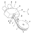
図2は、ゴム押出装置50によって押し出されたゴム押出物1を示している。ゴム押出装置50は、サイドウォールゴム11を押し出す筒状のゴム押出機51Aとクリンチゴム12を押し出す筒状のゴム押出機51Bと、ゴム押出機51A,51Bの先端に設けられた押出ヘッド52とを備えている。
FIG. 2 shows the rubber extrudate 1 extruded by the
ゴム押出機51Aの内部には、サイドウォールゴム11をゴム押出ヘッド52の側に押し出すためのスクリューが設けられている。同様に、ゴム押出機51Bの内部には、クリンチゴム12をゴム押出ヘッド52の側に押し出すためのスクリューが設けられている。ゴム押出ヘッド52の押出方向Xの先端には、ゴム押出物1を押出成形するためのプリフォーマー53と口金54とが設けられている。
Inside the
口金54は、プリフォーマー53の先端すなわち押出方向Xの下流側に装着されている。口金54には、ゴム押出物を吐出するための吐出口54aが形成されている。吐出口54aは、ゴム押出物1の目標とする断面形状に応じて、口金54を押出方向Xに貫通して開口されている。
The
ゴム押出装置50によって押し出されたゴム押出物1は、リール70によって巻き取られ、ゴム巻取体10として保管される。本実施形態では、リール70の径方向に隣り合うゴム押出物1の密着を防止するための樹脂フィルム15等が、貼り付けられている。樹脂フィルム15は、リール70によって巻き取られる前のゴム押出物1の裏面に、貼り付けられる。
The rubber extrudate 1 extruded by the
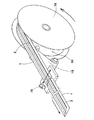
図3は、リール70及びゴム巻取体10の断面を示している。リール70は、ゴム押出装置50によって押し出されたゴム押出物1が巻き付けられるリール芯71と、ゴム押出物1をリール芯71に案内するためのフランジ72とを有している。
FIG. 3 shows a cross section of the
ゴム巻取体10では、図2に示されるゴム押出物1の巻き取り時に、ゴム押出物1に張力がかかり、ゴム押出物1の厚肉部5が、リール70に巻き取られている部分で、厚さ方向Z(リール径方向)に圧力を受ける。このような場合であっても、溝2は、ゴム押出物1の表面1Aから陥没して形成されているので、溝2自体には圧力は生じない。これにより、溝2の形状は潰れることなく維持され、タイヤ成形ドラムに対するゴム押出物の向きの識別性は、十分に維持される。
In the rubber wound
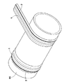
図4は、リール70から引き出されたゴム押出物1を示している。ゴム押出物1は、リール70から引き出され、樹脂フィルム15が剥離された後、カッター75によって予め定められた長さに裁断される。ゴム押出物1がリール70から引き出される際にも、上記の巻き取り時と同様に、ゴム押出物1に張力がかかり、ゴム押出物1の厚肉部5が、リール70に巻き取られている部分で、厚さ方向Zに圧力を受ける。このような場合であっても、溝2は、ゴム押出物1の表面1Aから陥没して形成されているので、上記と同様に、溝2の形状は潰れることなく維持される。
FIG. 4 shows the rubber extrudate 1 drawn from the
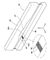
図5は、タイヤ成形ドラム80に巻き付けられる一対のゴム押出物1を示している。本実施形態では、溝2がタイヤ成形ドラム80の軸方向の外側に位置するように、ゴム押出物1の向きが決定される。これにより、ゴム押出物1は、タイヤ成形ドラム80に対して正しい向きで巻き付けられる。図5では、ゴム押出物1がタイヤ成形ドラム80の上に直接巻き付けられている例が示されているが、タイヤ成形ドラム80の上にインナーライナーゴム及びカーカスプライが巻き付けられ、さらにその上にゴム押出物1が巻き付けられていてもよい。
FIG. 5 shows a pair of rubber extrudates 1 wound around the
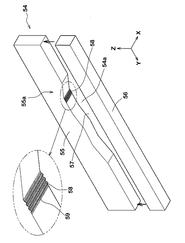
図6は、図2に示されるプリフォーマー53の先端に装着される口金54の一実施形態を示している。口金54は、第1口金55と第2口金56とを有している。第1口金55と第2口金56とは、ゴム押出物1の厚さ方向Zに併設されている。第1口金55には、ゴム押出物1に対応する断面形状の開口57が形成されている。開口57は、第1口金55を押出方向Xに貫通して形成されている。第1口金55の開口57と第2口金56の側面とによって、ゴム押出物1を吐出するための吐出口54aが形成される。
FIG. 6 shows an embodiment of a base 54 attached to the tip of the
第1口金55は、ゴム押出物1の厚肉部5に溝2を形成するための突条部58を有している。突条部58は、ゴム押出物1の一方側3に対応する第1口金55の一方側55aに形成されている。突条部58は、押出方向Xに連続して吐出口54aの内方に突出して形成されている。これにより、ゴム押出物1の押し出し時に、表面1Aに容易に溝2を形成することが可能となる。
The
突条部58及びその周辺部の表面には、めっき層59が形成されている。めっき層59は、ゴム押出物1の押し出し時に、表面1Aと突条部58等との摩擦を低減し、突条部58の摩耗を抑制する。
A
図7は、図2に示されるプリフォーマー53の先端に装着される口金54の別の実施形態である口金64を示している。口金64は、第1口金65と第2口金66とを有している。第1口金65には、ゴム押出物1に対応する断面形状の開口67が形成されている。第1口金65の開口67と第2口金66の側面とによって、ゴム押出物1を吐出するための吐出口64aが形成される。
FIG. 7 shows a base 64 which is another embodiment of the base 54 attached to the tip of the
本実施形態の口金64では、第2口金66は、ゴム押出物1の厚肉部5に溝2を形成するための突条部68を有している。突条部68は、ゴム押出物1の一方側3に対応する第2口金66の一方側66aに形成されている。突条部68は、押出方向Xに連続して吐出口64aの内方に突出して形成されている。これにより、ゴム押出物1の押し出し時に、ゴム押出物1の裏面に容易に溝2を形成することが可能となる。
In the
突条部68及びその周辺部の表面には、めっき層69が形成されている。めっき層69は、ゴム押出物1の押し出し時に、ゴム押出物1の裏面と突条部68等との摩擦を低減し、突条部68の摩耗を抑制する。
A
図6に示される口金54において、第1口金55又は第2口金56が、図2に示されるプリフォーマー53と一体的に形成されていてもよい。同様に、図7に示される口金64において、第1口金65又は第2口金66が、図2に示されるプリフォーマー53と一体的に形成されていてもよい。
In the base 54 shown in FIG. 6, the
以上、本発明のゴム押出物1、ゴム巻取体10、及びゴム押出装置50が詳細に説明されたが、本発明は上記の具体的な実施形態に限定されることなく種々の態様に変更して実施される。
As described above, the rubber extrudate 1, the
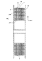
図1の基本構造をなし、サイズ11R22.5の重荷重用タイヤのサイドウォールゴムに適用されるゴム押出物が、表1の仕様に基づき試作され、巻付方向の識別手段の視認性及びタイヤの外観品質がテストされた。テスト方法は、以下の通りである。 A rubber extrudate that has the basic structure shown in FIG. 1 and is applied to the side wall rubber of a heavy-duty tire of size 11R22.5 is manufactured on the basis of the specifications shown in Table 1, and the visibility of the means for identifying the winding direction and the tire Appearance quality was tested. The test method is as follows.
<巻付方向の識別手段の視認性>
リールによって巻き取られた各ゴム押出物について、リール芯の近傍での巻付方向の識別手段の視認性が、作業者の官能により評価された。結果は、比較例1を100とする評点であり、数値が大きい程、視認性に優れていることを示す。
<Visibility of the means for identifying the winding direction>
For each rubber extrudate wound by the reel, the visibility of the means for identifying the winding direction in the vicinity of the reel core was evaluated by the operator's sensuality. A result is a score which sets the comparative example 1 to 100, and shows that it is excellent in visibility, so that a numerical value is large.
<タイヤの外観品質>
各ゴム押出物を用いて試作されたタイヤの外観品質が、作業者の官能により評価された。結果は、比較例1を100とする評点であり、数値が大きい程、外観品質に優れていることを示す。
<Tire appearance quality>
The appearance quality of the tires trial manufactured using each rubber extrudate was evaluated by the operator's sensuality. A result is a score which sets comparative example 1 to 100, and shows that it is excellent in appearance quality, so that a numerical value is large.
非対称形状のゴム押出物にあっては、比較例1に示されるように、ゴム押出物の巻付方向の識別手段として、押出方向に連続して突出する突条を適用することも可能である。しかしながら、表1から明らかなように、比較例1の突条は、ゴム押出物の厚さ方向にかかる圧力によって潰れるため、突条の視認性が悪化するおそれがある。 In the asymmetrically shaped rubber extrudate, as shown in Comparative Example 1, it is also possible to apply a ridge that continuously protrudes in the extruding direction as means for identifying the winding direction of the rubber extrudate. . However, as apparent from Table 1, the protrusion of Comparative Example 1 is crushed by the pressure applied in the thickness direction of the rubber extrudate, so that the visibility of the protrusion may be deteriorated.
これに対して各実施例の溝は、比較例に比べてゴム押出物の厚さ方向にかかる圧力によって潰れることがないため、溝の視認性が有意に向上することが確認できた。 On the other hand, since the groove | channel of each Example was not crushed by the pressure concerning the thickness direction of a rubber extrudate compared with a comparative example, it has confirmed that the visibility of a groove | channel improved significantly.
さらにまた、比較例の突条は、口金に溝を形成することによって、ゴムの押し出し時に成形できる。しかしながら、口金に形成された溝にゴムが詰まると、突条の突出高さが減少するため、突条の視認性が悪化するおそれがある。 Furthermore, the protrusion of the comparative example can be formed at the time of rubber extrusion by forming a groove in the base. However, if the groove formed in the base is clogged with rubber, the protrusion height of the protrusion is reduced, so that the visibility of the protrusion may be deteriorated.
これに対して各実施例では、口金に突条を形成することによって、ゴムの押し出し時に成形できる。このような口金では、ゴムの詰まりが発生しないので、溝の深さは維持されるため、溝の視認性が有意に向上することが確認できた。 On the other hand, in each Example, it can shape | mold at the time of extrusion of rubber | gum by forming a protrusion on a nozzle | cap | die. In such a base, since clogging of rubber does not occur, the depth of the groove is maintained, and it has been confirmed that the visibility of the groove is significantly improved.
1 ゴム押出物
2 溝
3 一方側
4 他方側
5 厚肉部
10 ゴム巻取体
11 サイドウォールゴム
12 クリンチゴム
50 ゴム押出装置
54 口金
54a 吐出口
58 突条部
59 めっき層
64 口金
64a 吐出口
68 突条部
69 めっき層
70 リール
80 タイヤ成形ドラム
CL 中心線
X 押出方向
Y 幅方向
DESCRIPTION OF SYMBOLS 1
Claims (9)
前記中心線によって隔てられる前記幅方向の一方側に、前記押出方向に連続し、前記タイヤ成形ドラムに対する前記ゴム押出物の向きを識別するための溝が形成されていることを特徴とするゴム押出物。 A rubber extrudate for forming a raw tire by being asymmetrically extruded with a thickness distribution with respect to a center line in the width direction in a cross section perpendicular to the extrusion direction and wound on a tire molding drum,
A rubber extrusion characterized in that, on one side of the width direction separated by the center line, a groove is formed continuously in the extrusion direction and for identifying the direction of the rubber extrudate with respect to the tire molding drum. object.
前記溝は、前記厚肉部に設けられている請求項1記載のゴム押出物。 The extrudate has a thick part on the one side that is thicker than the maximum thickness on the other side in the width direction,
The rubber extrudate according to claim 1, wherein the groove is provided in the thick part.
前記口金は、前記押出方向に連続して前記吐出口の内方に突出し、前記厚肉部に前記溝を形成する突条部を有することを特徴とするゴム押出装置。 A rubber extrusion apparatus comprising a die having a discharge port for discharging the rubber extrudate according to any one of claims 1 to 6,
The rubber extrusion device according to claim 1, wherein the die has a protruding portion that protrudes inward of the discharge port continuously in the extrusion direction and forms the groove in the thick portion.
The rubber extrusion device according to claim 8, wherein a plating layer is formed on a surface of the protruding portion.
Priority Applications (1)
| Application Number | Priority Date | Filing Date | Title |
|---|---|---|---|
| JP2014103626A JP2015217618A (en) | 2014-05-19 | 2014-05-19 | Rubber extrudate, rubber winder, and rubber extrusion device |
Applications Claiming Priority (1)
| Application Number | Priority Date | Filing Date | Title |
|---|---|---|---|
| JP2014103626A JP2015217618A (en) | 2014-05-19 | 2014-05-19 | Rubber extrudate, rubber winder, and rubber extrusion device |
Publications (1)
| Publication Number | Publication Date |
|---|---|
| JP2015217618A true JP2015217618A (en) | 2015-12-07 |
Family
ID=54777429
Family Applications (1)
| Application Number | Title | Priority Date | Filing Date |
|---|---|---|---|
| JP2014103626A Pending JP2015217618A (en) | 2014-05-19 | 2014-05-19 | Rubber extrudate, rubber winder, and rubber extrusion device |
Country Status (1)
| Country | Link |
|---|---|
| JP (1) | JP2015217618A (en) |
Cited By (2)
| Publication number | Priority date | Publication date | Assignee | Title |
|---|---|---|---|---|
| CN105818351A (en) * | 2016-03-29 | 2016-08-03 | 江苏通用科技股份有限公司 | Curvilinear tread combined prefabricated opening model |
| US20230294460A1 (en) * | 2020-09-01 | 2023-09-21 | Sumitomo Rubber Industries, Ltd. | Pneumatic tire |
Citations (5)
| Publication number | Priority date | Publication date | Assignee | Title |
|---|---|---|---|---|
| JPH10109367A (en) * | 1996-10-08 | 1998-04-28 | Bridgestone Corp | Method for detecting pasting condition of tire constituent member |
| JPH10249955A (en) * | 1997-03-10 | 1998-09-22 | Bridgestone Corp | Rubber extruding member and member-sticking method |
| JP2004284165A (en) * | 2003-03-20 | 2004-10-14 | Bridgestone Corp | Pneumatic tire manufacturing method |
| JP2008126649A (en) * | 2006-11-27 | 2008-06-05 | Sumitomo Rubber Ind Ltd | Pneumatic tire manufacturing method |
| JP2013043317A (en) * | 2011-08-23 | 2013-03-04 | Sumitomo Rubber Ind Ltd | Rubber extrusion molding apparatus |
-
2014
- 2014-05-19 JP JP2014103626A patent/JP2015217618A/en active Pending
Patent Citations (5)
| Publication number | Priority date | Publication date | Assignee | Title |
|---|---|---|---|---|
| JPH10109367A (en) * | 1996-10-08 | 1998-04-28 | Bridgestone Corp | Method for detecting pasting condition of tire constituent member |
| JPH10249955A (en) * | 1997-03-10 | 1998-09-22 | Bridgestone Corp | Rubber extruding member and member-sticking method |
| JP2004284165A (en) * | 2003-03-20 | 2004-10-14 | Bridgestone Corp | Pneumatic tire manufacturing method |
| JP2008126649A (en) * | 2006-11-27 | 2008-06-05 | Sumitomo Rubber Ind Ltd | Pneumatic tire manufacturing method |
| JP2013043317A (en) * | 2011-08-23 | 2013-03-04 | Sumitomo Rubber Ind Ltd | Rubber extrusion molding apparatus |
Cited By (2)
| Publication number | Priority date | Publication date | Assignee | Title |
|---|---|---|---|---|
| CN105818351A (en) * | 2016-03-29 | 2016-08-03 | 江苏通用科技股份有限公司 | Curvilinear tread combined prefabricated opening model |
| US20230294460A1 (en) * | 2020-09-01 | 2023-09-21 | Sumitomo Rubber Industries, Ltd. | Pneumatic tire |
Similar Documents
| Publication | Publication Date | Title |
|---|---|---|
| JP2008213773A (en) | Pneumatic tire and vulcanization molding apparatus for producing the same | |
| JP4375864B2 (en) | Pneumatic tire manufacturing method | |
| JP2017209958A (en) | Tire vulcanization mold | |
| JP6487758B2 (en) | Tire vulcanization mold, method for manufacturing pneumatic tire using the same, and pneumatic tire | |
| JP2006051711A (en) | Manufacturing method of rubber member for tire. | |
| CN101678625A (en) | Rubber member for tire, process for producing the same and process for manufacturing pneumatic tire | |
| JP6821953B2 (en) | Tire manufacturing method | |
| JP2015217618A (en) | Rubber extrudate, rubber winder, and rubber extrusion device | |
| KR101664873B1 (en) | Extruding mold die for tire sidewall extruding | |
| JP4904054B2 (en) | Manufacturing method of rubber member for tire | |
| JP2013043317A (en) | Rubber extrusion molding apparatus | |
| JP6587207B2 (en) | Tread, mold for tread molding, tread molding method, and green tire molding method | |
| JP5066220B2 (en) | Pneumatic tire and manufacturing method thereof | |
| JP5964209B2 (en) | Pneumatic tire manufacturing method and pneumatic tire | |
| JP7211786B2 (en) | Pneumatic tire manufacturing apparatus and manufacturing method | |
| JP4718215B2 (en) | Pneumatic tire manufacturing method | |
| JP6575342B2 (en) | Pneumatic tire manufacturing method and rubber strip | |
| JP6081153B2 (en) | Pneumatic tire manufacturing method and pneumatic tire | |
| JP5989380B2 (en) | Pneumatic tire manufacturing method and bead manufacturing apparatus | |
| JP5000276B2 (en) | Pneumatic tire manufacturing method | |
| JP2017056596A (en) | Tire vulcanization mold and method for manufacturing pneumatic tire using the same | |
| CN102371695B (en) | Airtyred manufacture method and shaped device | |
| KR102040038B1 (en) | Manufacturing method of pneumatic tire using tread rubber producing extrusion die non-final die | |
| JP2019001099A (en) | Pneumatic tire manufacturing method, tire vulcanizing mold, and pneumatic tire | |
| JP2002002224A (en) | Pneumatic tire and vulcanization die therefor |
Legal Events
| Date | Code | Title | Description |
|---|---|---|---|
| A621 | Written request for application examination |
Free format text: JAPANESE INTERMEDIATE CODE: A621 Effective date: 20170405 |
|
| A977 | Report on retrieval |
Free format text: JAPANESE INTERMEDIATE CODE: A971007 Effective date: 20171110 |
|
| A131 | Notification of reasons for refusal |
Free format text: JAPANESE INTERMEDIATE CODE: A131 Effective date: 20171205 |
|
| A521 | Request for written amendment filed |
Free format text: JAPANESE INTERMEDIATE CODE: A523 Effective date: 20180112 |
|
| A02 | Decision of refusal |
Free format text: JAPANESE INTERMEDIATE CODE: A02 Effective date: 20180220 |