JP2015202101A5 - - Google Patents
Download PDFInfo
- Publication number
- JP2015202101A5 JP2015202101A5 JP2014084915A JP2014084915A JP2015202101A5 JP 2015202101 A5 JP2015202101 A5 JP 2015202101A5 JP 2014084915 A JP2014084915 A JP 2014084915A JP 2014084915 A JP2014084915 A JP 2014084915A JP 2015202101 A5 JP2015202101 A5 JP 2015202101A5
- Authority
- JP
- Japan
- Prior art keywords
- clutch
- operation unit
- spool
- movable
- side plate
- Prior art date
- Legal status (The legal status is an assumption and is not a legal conclusion. Google has not performed a legal analysis and makes no representation as to the accuracy of the status listed.)
- Granted
Links
- 210000003813 Thumb Anatomy 0.000 description 14
- 239000002184 metal Substances 0.000 description 11
- 241000276420 Lophius piscatorius Species 0.000 description 8
- 238000004804 winding Methods 0.000 description 7
- 210000003811 Fingers Anatomy 0.000 description 5
- 239000007787 solid Substances 0.000 description 4
- 238000005452 bending Methods 0.000 description 3
- 229920003002 synthetic resin Polymers 0.000 description 3
- 239000000057 synthetic resin Substances 0.000 description 3
- XLYOFNOQVPJJNP-UHFFFAOYSA-N water Substances O XLYOFNOQVPJJNP-UHFFFAOYSA-N 0.000 description 3
- 230000002093 peripheral Effects 0.000 description 2
- 238000007747 plating Methods 0.000 description 2
- 241000251468 Actinopterygii Species 0.000 description 1
- 230000000694 effects Effects 0.000 description 1
- 210000004936 left thumb Anatomy 0.000 description 1
- 230000004048 modification Effects 0.000 description 1
- 238000006011 modification reaction Methods 0.000 description 1
- 229910052755 nonmetal Inorganic materials 0.000 description 1
- 230000000414 obstructive Effects 0.000 description 1
- 229920002866 paraformaldehyde Polymers 0.000 description 1
Images
Description
本発明は、操作部材、特に、釣り糸を前方に繰り出す両軸受リールのリール本体の後部に設けられ、クラッチ機構をクラッチオフ状態からクラッチオン状態に戻すための両軸受リールのクラッチ操作部材に関する。 The present invention relates to a clutch operating member for a dual-bearing reel that is provided at the rear part of a reel body of a dual-bearing reel that feeds fishing line forward and returns a clutch mechanism from a clutch-off state to a clutch-on state.
両軸受リールのリール本体の後部にクラッチ機構を操作するためのクラッチ操作部材を有するものが従来知られている。このようなクラッチ操作部材において、クラッチオン操作用の第1及び第2操作部と、クラッチオフ操作用の第3操作部とを有するものが従来知られている(例えば、特許文献1参照)。従来のクラッチ操作部材は、クラッチ機構をクラッチオン状態に操作するための第1操作部及び第2操作部を有する。第1操作部及び第2操作部は、スプールの両端の外周側に間隔を隔てて湾曲して配置される。第1操作部及び第2操作部は、クラッチオフ操作用の第3操作部によって連結される。したがって、クラッチ操作部材におおむねU字状に形成される。従来の両軸受リールのクラッチ操作部材では、リールを握る手の親指の先端をフランジ部に接触させてサミングを行うことができるとともに、第1操作部及び第2操作部の少なくともいずれか一方を親指の先端によって押圧してクラッチオン操作を行うことができる。 2. Description of the Related Art One having a clutch operating member for operating a clutch mechanism at the rear part of a reel body of a dual-bearing reel is conventionally known. Among such clutch operation members, those having first and second operation parts for clutch-on operation and third operation parts for clutch-off operation are conventionally known (see, for example, Patent Document 1). A conventional clutch operation member has a first operation part and a second operation part for operating the clutch mechanism to a clutch-on state. The first operation portion and the second operation portion are curvedly arranged at intervals on the outer peripheral sides of both ends of the spool. The first operation unit and the second operation unit are connected by a third operation unit for clutch-off operation. Accordingly, the clutch operating member is generally U-shaped. With the conventional clutch operating member of a dual-bearing reel, it is possible to perform summing by bringing the tip of the thumb of the hand gripping the reel into contact with the flange portion, and at least one of the first operating portion and the second operating portion is the thumb. The clutch-on operation can be performed by pressing with the tip of the.
従来のクラッチ操作部材では、サミングを行う際に、親指の先端を第1及び第2操作部のいずれかと湾曲してつながっている部分を滑らすだけで、スプールのフランジ部に到達させることができる。 In the conventional clutch operation member, when summing is performed, it is possible to reach the flange portion of the spool only by sliding the portion where the tip of the thumb is curved and connected to one of the first and second operation portions.
しかしながら、従来のクラッチ操作部材では、指をサミングするために、湾曲してつながっている部分から、第1操作部若しくは第2操作部の少なくともいずれか一方に、再び、滑らせて操作する必要がある。このため、クラッチ操作部材をクラッチオン位置に戻すクラッチ戻し操作を瞬時に行いにくい。 However, in the conventional clutch operation member, it is necessary to slide and operate again from at least one of the first operation unit and the second operation unit from the curved and connected portion in order to summing the fingers. is there. For this reason, it is difficult to instantaneously perform the clutch return operation for returning the clutch operation member to the clutch-on position.
本発明の課題は、サミング動作中であっても、クラッチ戻し操作を瞬時に行えるクラッチ操作部材を提供することにある。 An object of the present invention is to provide a clutch operating member capable of instantaneously performing a clutch return operation even during a summing operation.
本発明に係る両軸受リールのクラッチ操作部材は、釣り糸を前方に繰り出す両軸受リールのリール本体の後部に設けられる。クラッチ操作部材は、クラッチ機構をクラッチオフ状態からクラッチオン状態に戻すためのものである。クラッチ操作部材は、可動部と、第1操作部と、を備える。可動部は、クラッチ機構をクラッチオフ状態にするクラッチオフ位置とクラッチオン状態にするクラッチオン位置との間でリール本体に移動可能に設けられる。第1操作部は、可動部に両端が揺動可能に連結され、クラッチオフ位置からクラッチオン位置に可動部を戻すために設けられる。 The clutch operating member for a dual-bearing reel according to the present invention is provided at the rear part of the reel body of the dual-bearing reel for feeding fishing line forward. The clutch operating member is for returning the clutch mechanism from the clutch-off state to the clutch-on state. The clutch operation member includes a movable part and a first operation part. The movable portion is provided movably on the reel unit between a clutch-off position where the clutch mechanism is in a clutch-off state and a clutch-on position where the clutch mechanism is in a clutch-on state. The first operation unit is swingably coupled at both ends to the movable unit, and is provided to return the movable unit from the clutch-off position to the clutch-on position.
この両軸受リールのクラッチ操作部材では、クラッチ機構をクラッチオフ状態にして釣り糸を繰り出す場合には、可動部をクラッチオン位置からクラッチオフ位置に移動させる。また、クラッチ機構をクラッチオフ状態からクラッチオン状態に戻すときには、第1操作部を操作して可動部をクラッチオフ位置からクラッチオン位置に戻す。この第1操作部は、可動部に両端が揺動可能に連結される。このため、指(親指)を第1操作部に当てた状態で、第1操作部をスプールに近づく方向に揺動させてサミング動作を行うことができる。これによって、サミング動作から、クラッチ戻し操作を瞬時に行えるようになる。 In the clutch operating member of the dual- bearing reel, the movable portion is moved from the clutch-on position to the clutch-off position when the fishing line is fed out with the clutch mechanism in the clutch-off state. Further, when the clutch mechanism is returned from the clutch-off state to the clutch-on state, the first operating portion is operated to return the movable portion from the clutch-off position to the clutch-on position. Both ends of the first operation unit are swingably coupled to the movable unit. Therefore, the summing operation can be performed by swinging the first operation unit in a direction approaching the spool while the finger (thumb) is applied to the first operation unit. As a result, the clutch return operation can be instantaneously performed from the summing operation.
第1操作部は、弾性を有する金属線材製であってもよい。この場合には、金属線材を倒立U字状に湾曲させ、その両端を可動部に揺動可能に連結することによって、第1操作部を外観上目立たなくすることができる。また、第1操作部を、例えばめっき加工などの装飾加工することによって、外観上の特徴を強調することもできる。 The first operation unit may be made of a metal wire having elasticity. In this case, the first operating portion can be made inconspicuous by curving the metal wire in an inverted U shape and connecting both ends of the metal wire to the movable portion so as to be swingable. Further, the appearance feature can be emphasized by decorating the first operation unit, for example, by plating.
リール本体は、前後方向と交差する左右方向に間隔を隔てて配置される第1側板及び第2側板を有する。可動部は、第1側板と第2側板との間に移動可能に配置されてもよい。この場合には、可動部が両端で案内されるので、可動部が左右に傾きにくくなる。 The reel body has a first side plate and a second side plate that are spaced apart in the left-right direction intersecting the front-rear direction. The movable part may be arranged to be movable between the first side plate and the second side plate. In this case, since the movable part is guided at both ends, the movable part is less likely to tilt left and right.
第1操作部の長さは、第1側板と第2側板の間隔よりも長くてもよい。この場合には、第1操作部を容易に湾曲させることができる。 The length of the first operation unit may be longer than the distance between the first side plate and the second side plate. In this case, the first operation unit can be easily bent.
第1操作部は、湾曲して配置されてもよい。この場合には、両軸受リールを握っている手の親指で第1操作部を操作しやすくなる。 The first operation unit may be curved and arranged. In this case, it becomes easy to operate the first operation unit with the thumb of the hand holding the both bearing reels.
第1操作部は、可動部に着脱可能に設けられてもよい。この場合には、第1操作部を用いずにクラッチオン操作を行う釣り人の場合には、第1操作部を外すことができ、釣り人の好みに合わせて第1操作部を選択できる。例えば、可動部によってクラッチオン位置への操作を行う釣り人、又はハンドルの糸巻き取り方向の回転によってクラッチ機構をクラッチオフ状態からクラッチオン状態に戻す操作を行う釣り人などは、第1操作部を外してもよい。 The 1st operation part may be provided in a movable part so that attachment or detachment is possible. In this case, in the case of an angler who performs a clutch-on operation without using the first operation unit, the first operation unit can be removed, and the first operation unit can be selected according to the preference of the angler. For example, an angler who operates the clutch on position with the movable part, or an angler who performs an operation to return the clutch mechanism from the clutch off state to the clutch on state by rotating the handle in the line winding direction, etc. May be removed.
第1操作部は、両端が前後方向に回動可能に可動部に連結されてもよい。この場合には、第1操作部が前後方向に回動するので、前方に配置することによってクラッチオン操作を行え、後方に配置することによって、バックラッシュに対処しやすくなる。 The first operation unit may be coupled to the movable unit so that both ends thereof are rotatable in the front-rear direction. In this case, since the first operation portion rotates in the front-rear direction, the clutch-on operation can be performed by arranging the first operation unit in the front direction, and the backlash can be easily dealt with by arranging the first operation unit in the rear direction.
クラッチ操作部材は、可動部に設けられ、クラッチオン位置からクラッチオフ位置に可動部を移動させるための第2操作部をさらに備えてもよい。この場合には、第2操作部によって、クラッチオン位置からクラッチオフ位置に操作しやすくなる。 The clutch operation member may further include a second operation unit that is provided on the movable unit and moves the movable unit from the clutch-on position to the clutch-off position. In this case, the second operation unit facilitates operation from the clutch-on position to the clutch-off position.
本発明によれば、指(親指)を第1操作部に当てた状態で、第1操作部をスプールに近づく方向に揺動させてサミング動作を行うことができる。これによって、サミング動作から、クラッチ戻し操作を瞬時に行えるようになる。 According to the present invention, it is possible to perform a summing operation by swinging the first operation unit in a direction approaching the spool while the finger (thumb) is applied to the first operation unit. As a result, the clutch return operation can be instantaneously performed from the summing operation.
<第1実施形態>
図1において、本発明の第1実施形態を採用した両軸受リールは、釣り糸を前方に外部電源から供給された電力により駆動されるとともに、手巻きのリールとして使用するときの電源を内部に有する小型の電動リール100である。また、電動リール100は糸繰り出し長さ又は糸巻取長さに応じて仕掛けの水深を表示する水深表示機能を有する。
<First Embodiment>
In FIG. 1, a dual-bearing reel adopting the first embodiment of the present invention is driven by electric power supplied from an external power source to a fishing line forward, and has a power source for use as a manually wound reel. This is a small
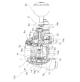
電動リール100は、リール本体1と、ハンドル2と、仕掛けの水深を表示可能な水深表示部4と、糸巻用のスプール10と、クラッチ操作部材11と、モータ(図示せず)と、スプール駆動機構13と、クラッチ機構16と、を備える。ハンドル2は、リール本体1に回転可能に設けられる。スプール10は、リール本体1に回転可能に設けられる。クラッチ操作部材11は、クラッチ機構16をオンオフ操作するためのものであり、リール本体1の後部に移動可能に設けられる。モータは、リール本体1に設けられ、スプール10を回転駆動する。クラッチ機構16は、ハンドル2の回転をスプール10に伝達可能なクラッチオン状態と、ハンドル2の回転をスプール10に伝達不能なクラッチオフ状態と、にクラッチ操作部材11の操作によって切換可能である。
The
<リール本体>
リール本体1は、フレーム7と、第1側カバー8aと、第2側カバー8bと、を備える。フレーム7は、図2及び図3に示すように、例えば合成樹脂又は金属製の一体形成された部材である。フレーム7は、第1側板7aと、第2側板7bと、第1側板7aと第2側板7bとを連結する複数の連結部材7cと、を有する。下部に配置された連結部材7cには、釣り竿に電動リール100を装着するための釣り竿装着部7gが設けられる。第2側板7bは、第1側板7aと左右方向(図2左右方向)に間隔を隔てて配置される。図1に示すように、第1側カバー8aは、フレーム7のハンドル2装着側を覆う。第2側カバー8bは、フレーム7のハンドル2装着側と逆側を覆う。
<Reel body>
The reel body 1 includes a
図2に示すように、第1側板7aは、側板本体19aと、側板本体19aと間隔を隔てて配置され、各種の機構を装着するための機構装着板19bを有する。機構装着板19bは、側板本体19aの外側面にネジ止め固定されている。側板本体19aと第1側カバー8aとの間に、スプール駆動機構13と、クラッチ機構16を制御するクラッチ制御機構20と、スプール10の糸繰り出し方向の回転を制動するドラグ機構23(図3参照)と、が設けられる。
As shown in FIG. 2, the
第2側板7bには、図2に示すように、スプール10が通過可能な円形開口7fが形成されている。円形開口7fには、スプール10のスプール軸14の第1端(図2左端)を回転自在に支持するスプール支持部17が芯出しされて装着されている。スプール支持部17は、第2側板7bの外側面にネジ止め固定されている。スプール支持部17には、スプール軸14の第1端を支持する第1軸受18aが収納される。
As shown in FIG. 2, the
第1側カバー8a及び第1側板7aは、ハンドル2とともに回転する駆動軸30(図3参照)を回転自在に支持する。第2側カバー8bは、第2側板7bの外縁部に例えばネジ止めされる。
The
ハンドル2は、第1側カバー8a側に設けられている。ハンドル2は、図1に示すように、ハンドルアーム2aと、ハンドルアーム2aの先端に装着されたハンドル把手2bと、を有している。
The
<スプール>
スプール10は、スプール軸14に一体回転可能に装着されている。スプール軸14は、糸巻胴部10aの内周部に圧入等の適宜の固定手段により固定されている。
<Spool>
The
スプール軸14の第1端は、前述したようにスプール支持部17において第1軸受18aにより支持されている。スプール軸14の第2端(図2右端)は、第1側カバー8aに第2軸受18bにより支持されている。
The first end of the
スプール軸14のスプール固定部分より第2軸受18b側には、クラッチ機構16を構成するクラッチピン16aが径方向を貫通して装着されている。
A
<スプール駆動機構>
スプール駆動機構13は、スプール10を糸巻取方向に駆動する。また、巻取時にスプール10にドラグ力を発生させて釣り糸の切断を防止する。なお、スプール駆動機構13の説明では、モータからスプール10への駆動機構についての説明は省略する。
<Spool drive mechanism>
The
スプール駆動機構13は、図3に示すように、ハンドル2が一体回転可能に連結された駆動軸30と、駆動ギア31と、ドラグ機構23と、図示しない段付きギアと、を有している。ハンドル2の回転は、駆動軸30、ドラグ機構23及び段付きギアを介して中間ギア61に伝達される。この中間ギア61にピニオンギア32がかみ合う。
As shown in FIG. 3, the
ピニオンギア32は、図2に示すように、側板本体19aにスプール軸14回りに回転自在かつ軸方向移動自在に装着されている。ピニオンギア32は、クラッチ制御機構20により制御されて、図2に示すクラッチオン位置と、クラッチオン位置よりも図2右側のクラッチオフ位置と、の間で軸方向にスプール軸14の外周側を移動する。ピニオンギア32は、クラッチヨーク41に係合してスプール軸14方向に移動する。
As shown in FIG. 2, the
駆動軸30(図3参照)は、図示しないワンウェイクラッチにより糸繰り出し方向の回転が禁止されている。図3に示すように、駆動ギア31は、駆動軸30に回転自在に装着されている。駆動ギア31は、ドラグ機構23により糸繰り出し方向の回転が制動される。これにより、スプール10の糸繰り出し方向の回転が制動される。
The drive shaft 30 (see FIG. 3) is prohibited from rotating in the yarn drawing direction by a one-way clutch (not shown). As shown in FIG. 3, the drive gear 31 is rotatably mounted on the drive shaft 30. The drive gear 31 is braked by the drag mechanism 23 for rotation in the yarn drawing direction. As a result, the rotation of the
<クラッチ機構>
クラッチ機構16は、図2に示すように、クラッチピン16aと、ピニオンギア32の左側端面に径方向に沿って十字に凹んで形成されたクラッチ凹部16bと、を有している。ピニオンギア32は、クラッチ機構16を構成するとともに、スプール駆動機構13を構成する。ピニオンギア32は、前述したように、図2に示すクラッチオン位置とクラッチオフ位置との間で移動する。
クラッチオン位置では、クラッチピン16aがクラッチ凹部16bに係合してピニオンギア32の回転がスプール軸14に伝達され、クラッチ機構16は、クラッチオン状態になる。このクラッチオン状態では、ピニオンギア32とスプール軸14とが一体回転可能になる。また、クラッチオフ位置では、クラッチ凹部16bがクラッチピン16aから離反してピニオンギア32の回転がスプール軸14に伝達されない。このため、クラッチ機構16は、クラッチオフ状態になり、スプール10は自由回転可能になる。
<Clutch mechanism>
As shown in FIG. 2, the
At the clutch-on position, the
<クラッチ制御機構>
クラッチ制御機構20は、クラッチ操作部材11のクラッチオン位置とクラッチオフ位置との間の移動によって、クラッチ機構16をクラッチオン状態とクラッチオフ状態とに切り換えるために設けられる。クラッチ制御機構20は、図3に示すように、クラッチカム40と、クラッチヨーク41と、クラッチプレート42と、を有する。クラッチカム40は、スプール軸14回りに第1位置(クラッチオンの位置)と第2位置(クラッチオフの位置)との間で回動する。クラッチヨーク41は、クラッチカム40に係合する。クラッチプレート42は、クラッチカム40とクラッチ操作部材11とを連結する。クラッチプレート42は、クラッチカム40と一体的に回動する。クラッチカム40は、機構装着板19bに回動自在に支持される。クラッチカム40は、回動によってクラッチヨーク41を移動させるための一対のカム部40aを有する。
<Clutch control mechanism>
The
クラッチヨーク41は、ピニオンギア32をスプール軸方向にクラッチオフ位置とクラッチオン位置に移動させるために設けられる。クラッチヨーク41は、クラッチカム40のカム部40aに係合するカム受け部(図示せず)と、ピニオンギア32に係合する円弧部41aを有する。クラッチヨーク41は、クラッチカム40が第1位置から第2位置に回動すると、クラッチオン位置からスプール軸方向外方(図2右側)のクラッチオフ位置に移動する。これにより、ピニオンギア32が軸方向外方(図2右側)のクラッチオフ位置に移動し、ピニオンギア32とクラッチピン16aとの係合が解除され、クラッチ機構16がクラッチオフ状態になる。クラッチヨーク41は、図2に示す機構装着板19bに装着された一対のガイド軸49によって軸方向に案内される。図3に示すように、クラッチヨーク41は、ガイド軸49に装着された一対のコイルバネ44によってクラッチオン位置に向けて付勢される。したがって、クラッチカム40が第2位置から第1位置に回動すると、クラッチヨーク41は、クラッチオフ位置からクラッチオン位置に戻り、ピニオンギア32がクラッチオン位置に戻る。なお、クラッチカム40の第2位置から第1位置への復帰動作は、クラッチ操作部材11の後述する第1操作部52を用いた操作、又はクラッチオフ状態でのハンドル2の糸巻取方向に回転によって動作するクラッチ戻し機構60の動作、によって実現される。図3に示すように、クラッチ戻し機構60は、クラッチカム40に連結されたクラッチ爪62と、駆動軸30に一体回転可能に連結されたラチェットホイール64と、によって構成される。
The
クラッチプレート42は、クラッチ操作部材11の揺動によってクラッチカム40を回動させるために設けられる。クラッチプレート42は、例えば金属板を折り曲げて形成される。クラッチプレート42は、クラッチカム40に係合する係合部42aと、係合部42aから径方向に延びた後にクラッチ操作部材11に向けて折れ曲がる装着部42bと、を有する。係合部42aは、クラッチカム40の回動に連動して回動する。装着部42bは、クラッチ操作部材11に、例えばネジ部材によって固定される。
The clutch plate 42 is provided for rotating the clutch cam 40 by swinging of the
<クラッチ操作部材>
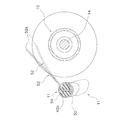
図3、図4及び図5に示すように、クラッチ操作部材11は、クラッチ機構16を、少なくもとクラッチオフ状態とクラッチオン状態に戻すために設けられる。第1実施形態では、クラッチ操作部材11は、クラッチ機構16をクラッチオン状態とクラッチオフ状態とに切り換え操作可能である。クラッチ操作部材11は、第1側板7aと第2側板7bとの間でリール本体1の後部に釣り竿装着部7gに対して接近及び離反する方向に移動可能に設けられる。第1実施形態では、クラッチ操作部材11は、スプール軸14の軸回りに揺動可能に設けられる。クラッチ操作部材11は、図5に実線で示すクラッチオン位置と、クラッチオン位置よりも釣り竿装着部7gに接近した図5に一点鎖線で示すクラッチオフ位置と、の間で揺動する。クラッチオン位置にクラッチ操作部材11を操作すると、クラッチ機構16は、クラッチオン状態になる。クラッチオフ位置にクラッチ操作部材11を操作すると、クラッチ機構16は、クラッチオフ状態になる。
<Clutch operating member>
As shown in FIGS. 3, 4 and 5, the
第1側板7aの後部及び第2側板7bの後部の内側面には、図3に示すように、第1接触板43a及び第2接触板43bが各別に装着される。第1接触板43a及び第2接触板43bは、クラッチプレート42の装着部42bが貫通かつ揺動可能な円弧状の通過孔43cをそれぞれ有する。第1接触板43a及び第2接触板43bは、ポリアセタール等の摺動性が高い合成樹脂製の部材である。第1接触板43a及び第2接触板43bは、第1側板7a及び第2側板7bに各別に着脱可能に嵌め込まれている。クラッチ操作部材11は、両端部が第1接触板43a及び第2接触板43bに接触可能な長さを有する。したがって、第1実施形態では、クラッチ操作部材11は、リール本体1に両端支持される。
As shown in FIG. 3, a first contact plate 43a and a second contact plate 43b are separately attached to the inner side surfaces of the rear portion of the
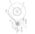
クラッチ操作部材11は、図4、図5及び図6に示すように、可動部50と、第1操作部52と、第2操作部54と、を有する。可動部50は、クラッチオン位置とクラッチオフ位置との間でリール本体1に移動可能に設けられる。第1操作部52は、可動部50に両端が揺動可能に連結される。第2操作部54は、可動部50に設けられる。可動部50は、第1側板7aと第2側板7bとの間に移動可能に配置される。可動部50は、第1接触板43a及び第2接触板43bにそれぞれ接触可能な第1接触面50a及び第2接触面50bを両端部に有する。また、可動部50は、クラッチプレート42の装着部42bに固定される矩形断面の貫通孔50cを有する。貫通孔50cは、第1接触面50aと第2接触面50bとを貫通して形成される。貫通孔50cは、クラッチプレート42の装着部42bの厚み及び幅と実質的に等しい矩形形状に形成される。クラッチプレート42の装着部42bは、第1接触板43a、貫通孔50c、及び第2接触板43bを貫通して配置される。これより、可動部50が装着部42bに装着される。したがって、第1実施形態では、可動部50は、両端が第1接触板43a及び第2接触板43bによって挟まれて装着部42bに装着されており、ネジなどの固定部材によって固定されてはいない。可動部50の上面には、中央部が僅かに凹むように湾曲して形成された第2操作部54が設けられる。第2操作部54は、クラッチオン位置からクラッチオフ位置に可動部50を下方に移動させるために設けられる。
As shown in FIGS. 4, 5, and 6, the
第1操作部52は、可動部50に両端が揺動可能に連結され、クラッチオフ位置からクラッチオン位置に可動部50を戻すために設けられる。第1操作部52は、たとえば、弾性を有する金属線材製の部材である。第1実施形態では、第1操作部52は、バネ線材を湾曲させて形成される。第1操作部52の長さは、第1側板7aと第2側板7bとの間隔よりも長い。第1操作部52は、例えば、倒立U字状に湾曲して配置される。第1操作部52は、図4に二点鎖線で示すように、可動部50に着脱可能に設けられる。第1操作部52は、図5に示すように、実線で示す初期位置と、初期位置よりもスプール10に近づいたサミング可能な揺動位置と、に揺動可能に両端が可動部50に連結される。揺動位置は、操作する指先(例えば電動リール100を握る左手の親指の指先)に力を入れて、第1操作部52をたわませることによって得られる。また、第1操作部52は、図6に示すように、前後方向に図6に実線で示す操作位置と、二点鎖線で示す開放位置と、に軸心C回りに回動可能である。軸心Cは、後述する第1環状溝50dの円形の底部の中心を通り、スプール軸14と平行な軸心である。
The
第1操作部52を回動可能、揺動可能かつ着脱可能に連結するために、可動部50の第1接触面50a及び第2接触面50bの軸方向の内側部分には、第1環状溝50d及び第2環状溝50eが設けられる。図6に示すように第1環状溝50d及び第2環状溝50eは底部が円形に形成された溝である。第1環状溝50d及び第2環状溝50eの底部には、周方向に間隔を隔てて配置された第1位置決め凹部50fと第2位置決め凹部50gがそれぞれ形成される。第1位置決め凹部50fは、第1操作部52を操作位置に位置決めするための位置決め凹部である。第2位置決め凹部50gは、第2操作部54を開放位置に位置決めするための位置決め凹部である。
In order to connect the
第1操作部52の両端部には、第1環状溝50dに係合する第1取付部52aと、第2環状溝50eに係合する第2取付部52bが形成される。第1取付部52a及び第2取付部52bは、円弧状に概ね180度を超える範囲(例えば240度程度の範囲)で湾曲して形成される。したがって、第1取付部52a及び第2取付部52bの先端部は開いている。
At both ends of the
第1取付部52aの先端部には、第1位置決め凹部50f及び第2位置決め凹部50gに係合して第1操作部52を操作位置と開放位置とに位置決めするための第1位置決め部52cが径方向内側に湾曲して形成される。第2取付部52bの先端部にも、第1位置決め凹部50f及び第2位置決め凹部50gに係合して第1操作部52を操作位置と開放位置とに位置決めするための第2位置決め部52dが径方向内側に湾曲して形成される。なお、第1位置決め凹部50fと第2位置決め凹部50g及び第1位置決め部52c及び第2位置決め部52dを両側ではなく片側だけに設けてもよい。
A first positioning portion 52c for engaging the first positioning recess 50f and the second positioning recess 50g to position the
第1位置決め部52c及び第2位置決め部52dが第1位置決め凹部50fに係合すると、第1操作部52は、図6に実線で示す操作位置に位置決めされる。第1位置決め部52c及び第2位置決め部52dが第2位置決め凹部50gに係合すると、第1操作部52は、図6に二点鎖線で示す開放位置に位置決めされる。第1操作部52が操作位置に配置されると、電動リール100を持つ手(例えば右ハンドルの場合は左手)の親指の指先で第1操作部52の湾曲した中間部52e(図4及び図5参照)を揺動位置に揺動させてサミング操作を行うことができるとともに、サミング操作に連続してクラッチ戻し操作を行うことができる。
When the first positioning portion 52c and the second positioning portion 52d are engaged with the first positioning recess 50f, the
<両軸受リールの操作>
このように構成された電動リール100では、釣りを行うときは、釣り人は釣り竿を持つ手の親指によってクラッチ操作部材11の例えば第2操作部54を押し下げ操作する。これにより、クラッチ機構16がクラッチオン状態からクラッチオフ状態に切り換わり、スプール10が自由回転状態になる。そして、仕掛けの自重によって釣り糸を繰り出し、仕掛けを魚が群れる棚位置まで下ろす。この釣り糸の繰り出し時に、スプール10に対してサミング操作を行う場合、第1操作部52に向けて親指を伸ばす。すると、親指の先端部が第1操作部52の中間部52eに接触した状態で親指の指先に力を入れることによって、第1操作部52がたわむ。これによって、第1操作部52を図5に二点鎖線で示す揺動位置に配置できる。第1操作部52が揺動位置に揺動すると、第1操作部52の中間部52eがスプール10に接近する。この結果、第1操作部52を操作する指の先端部よりも根元側がスプール10に巻き付けられた釣り糸に接触可能になる。そして、仕掛けが棚位置に到達すると、サミングしていた親指の先端部で第1操作部52の中間部52eを押し上げることによって、クラッチ操作部材11をクラッチオフ位置からクラッチオン位置に戻すことができる。したがって、サミング動作から、クラッチ戻し操作を瞬時に行えるようになる。この状態で獲物が掛かると、ハンドル2を操作することによって、釣り糸を巻き上げて獲物を釣り上げることができる。
<Operation of double-bearing reel>
In the
また、バックラッシュしたとき場合には、第1操作部52を後方に回動させる。第1操作部52を後方に回動させると、第1位置決め凹部50fに位置決めされた第1操作部52の第1位置決め部52c及び第2位置決め部52dが第1位置決め凹部50fから外れる。そして、第1位置決め部52c及び第2位置決め部52dが第2位置決め凹部50gに到達すると、弾性によって第1位置決め部52c及び第2位置決め部52dが第2位置決め凹部50gに係合し、開放位置で位置決めされる。この開放位置では、スプール10の糸巻き部分に邪魔な部材が無くなるため、スプール10をアクセスしやすくなり、バックラッシュに対処しやすくなる。さらに、第1操作部52を用いない釣りを行う場合には、第1操作部52を取り外すこともできる。第1操作部52を取り外す場合は、操作位置に配置された第1操作部52を斜め下方に移動させれば、第1取付部52a及び第2取付部52bが弾性的に拡がって、第1環状溝50d及び第2環状溝50eから第1操作部52が外れる。
Further, when backlash occurs, the
<第2実施形態> Second Embodiment
第1実施形態では、第1操作部52をたわませることによって揺動させているが、第2実施形態では、図7に示すように、軸心C回りに揺動させることによって、第1操作部152をスプール10に近づけるようにする。図7において、可動部150は、図示しない第1接触面及び第2接触面から軸方向内側に向けて環状に凹んで形成された第1取付凹部150h及び第2取付凹部150iを有する。第1取付凹部150h及び第2取付凹部150iには、第1接触面及び第2接触面から軸方向内側に延びる第1係止溝150j及び第2係止溝150kが形成される。
In the first embodiment, the
第1操作部152の両端部には、第1取付凹部150h及び第2取付凹部150iに装着される第1取付部152a及び第2取付部152bが形成される。第1取付部152a及び第2取付部152bは、渦巻き状に湾曲して形成されたゼンマイバネで構成される。第2実施形態では、第1取付部152a及び第2取付部152bは、二重の渦巻きバネによって構成される。第1取付部152a及び第2取付部152bの先端部には、径方向内側に折り曲げられて形成された第1係止部152c及び第2係止部152dが設けられる。第1係止部152cは、第1係止溝150jによって係止され、第2係止部152dは、第2係止溝150kによって係止される。
A
このような構成の第2実施形態では、第1操作部152が、たわんで揺動するのではなく、第1操作部152の中間部152eに指先で力を加えて第1操作部152をスプール10に近づけると、第1取付部152a及び第2取付部152bのゼンマイバネが伸びて中間部152eが実質的に軸心C回りに揺動する。このような構成のクラッチ操作部材111であっても、第1実施形態と同様な作用効果を奏する。
In the second embodiment having such a configuration, the
<他の実施形態>
以上、本発明の一実施形態について説明したが、本発明は上記実施形態に限定されるものではなく、発明の要旨を逸脱しない範囲で種々の変更が可能である。特に、本明細書に書かれた複数の実施形態及び変形例は必要に応じて任意に組合せ可能である。
<Other embodiments>
As mentioned above, although one Embodiment of this invention was described, this invention is not limited to the said embodiment, A various change is possible in the range which does not deviate from the summary of invention. In particular, a plurality of embodiments and modifications described in this specification can be arbitrarily combined as necessary.
(a)第1及び第2実施形態では、クラッチ操作部材11を第1側板7a及び第2側板7bで両端支持したが、本発明はこれに限定されない。クラッチ操作部材を第1側板側に片持ち支持してもよい。
(A) In the first and second embodiments, the
(b)第1及び第2実施形態では、クラッチ操作部材11がスプール軸14回りに揺動したが、クラッチ操作部材は、釣り竿装着部7gと接近及び離反する方向に移動するものであればどのように移動させてもよい。例えば、クラッチ操作部材をスプール軸と別の軸回りに揺動させてもよく、また、上下に直線的に移動させてもよい。
(B) In the first and second embodiments, the
(c)第1及び第2実施形態では、弾性を有する金属線線材製の第1操作部52を開示したが、本発明はこれに限定されない。弾性を有する合成樹脂などの非金属製の部材によって第1操作部を構成してもよい。また、弾性を有さない金属又は非金属によって第1操作部を構成してもよい。この場合、弾性部材を別に設けて弾性を付与するようにしてもよい。
(C) In 1st and 2nd embodiment, although the
(d)第1及び第2実施形態では、両軸受リールとして電動リール100を例示したが、通常の手巻きの両軸受リールにも本発明を適用できる。
(D) In the first and second embodiments, the
(e)第1実施形態では、第1操作部52を可動部50に対して着脱可能に構成したが、本発明はこれに限定されない。第1操作部を可動部に対して着脱不能に構成してもよい。
(E) In the first embodiment, the
(f)第1実施形態では、第1操作部52を操作位置と開放位置とに回動可能に構成したが、回動不能に構成してもよい。
(F) In the first embodiment, the
<特徴>
上記実施形態は、下記のように表現可能である。
<Features>
The above embodiment can be expressed as follows.
(A)電動リール100のクラッチ操作部材11は、釣り糸を前方に繰り出す電動リール100のリール本体1の後部に設けられる。クラッチ操作部材11は、クラッチ機構16をクラッチオフ状態からクラッチオン状態に戻すためのものである。クラッチ操作部材11は、可動部50と、第1操作部52と、を備える。可動部50は、クラッチ機構16をクラッチオフ状態にするクラッチオフ位置とクラッチオン状態にするクラッチオン位置との間でリール本体1に移動可能に設けられる。第1操作部52は、可動部50に両端が揺動可能に連結され、クラッチオフ位置からクラッチオン位置に可動部50を戻すために設けられる。
(A) The
この電動リール100のクラッチ操作部材11では、クラッチ機構16をクラッチオフ状態にして釣り糸を繰り出す場合には、可動部50をクラッチオン位置からクラッチオフ位置に移動させる。また、クラッチ機構16をクラッチオフ状態からクラッチオン状態に戻すときには、第1操作部52を操作して可動部50をクラッチオフ位置からクラッチオン位置に戻す。この第1操作部52は、可動部50に両端が揺動可能に連結される。このため、指(親指)を第1操作部52に当てた状態で、第1操作部52をスプール10に近づく方向に揺動させてサミング動作を行うことができる。これによって、サミング動作から、クラッチ戻し操作を瞬時に行えるようになる。
In the
(B)第1操作部52は、弾性を有する金属線材製であってもよい。この場合には、金属線材を倒立U字状に湾曲させ、その両端を可動部50に揺動可能に連結することによって、第1操作部52を外観上目立たなくすることができる。また、第1操作部52を、例えばめっき加工などの装飾加工することによって、外観上の特徴を強調することもできる。
(B) The
(C)リール本体1は、前後方向と交差する左右方向に間隔を隔てて配置される第1側板7a及び第2側板7bを有する。可動部50は、第1側板7aと第2側板7bとの間に移動可能に配置されてもよい。この場合には、可動部50が両端で案内されるので、可動部50が左右に傾きにくくなる。
(C) The reel body 1 includes a
(D)第1操作部52の長さは、第1側板7aと第2側板7bの間隔よりも長くてもよい。この場合には、第1操作部52を容易に湾曲させることができる。
(D) The length of the
(E)第1操作部52は、湾曲して配置されてもよい。この場合には、電動リール100を握っている手の親指で第1操作部52を操作しやすくなる。
(E) The
(F)第1操作部52は、可動部50に着脱可能に設けられてもよい。この場合には、第1操作部52を用いずにクラッチオン操作を行う釣り人の場合には、第1操作部52を外すことができ、釣り人の好みに合わせて第1操作部52を選択できる。例えば、可動部50によってクラッチオン位置への操作を行う釣り人、又はハンドル2の糸巻き取り方向の回転によってクラッチ機構16をクラッチオフ状態からクラッチオン状態に戻す操作を行う釣り人などは、第1操作部を外してもよい。
(F) The
(G)第1操作部52は、両端が前後方向に回動可能に可動部50に連結されてもよい。この場合には、第1操作部52が前後方向に回動するので、前方に配置することによってクラッチオン操作を行え、後方に配置することによって、バックラッシュに対処しやすくなる。
(G) The
(H)クラッチ操作部材11は、可動部50に設けられ、クラッチオン位置からクラッチオフ位置に可動部を移動させるための第2操作部54をさらに備えてもよい。この場合には、第2操作部54によって、クラッチオン位置からクラッチオフ位置に操作しやすくなる。
(H) The
1 リール本体
2 ハンドル
7a 第1側板
7b 第2側板
11 クラッチ操作部材
16 クラッチ機構
50 可動部
52 第1操作部
54 第2操作部
DESCRIPTION OF SYMBOLS 1
Priority Applications (6)
| Application Number | Priority Date | Filing Date | Title |
|---|---|---|---|
| JP2014084915A JP6368525B2 (en) | 2014-04-16 | 2014-04-16 | Clutch operating member for dual-bearing reel |
| KR1020140171962A KR102329829B1 (en) | 2014-04-16 | 2014-12-03 | Clutch operating apparatus for dual bearing reel |
| TW104100544A TWI632851B (en) | 2014-04-16 | 2015-01-08 | Clutch operating apparatus for dual bearing reel |
| US14/609,250 US9591838B2 (en) | 2014-04-16 | 2015-01-29 | Clutch operating member of a dual-bearing reel |
| CN201510065312.5A CN105028358B (en) | 2014-04-16 | 2015-02-06 | Clutch operating member for dual-bearing reel |
| MYPI2015700895A MY183972A (en) | 2014-04-16 | 2015-03-20 | Clutch operating member of a dual-bearing reel |
Applications Claiming Priority (1)
| Application Number | Priority Date | Filing Date | Title |
|---|---|---|---|
| JP2014084915A JP6368525B2 (en) | 2014-04-16 | 2014-04-16 | Clutch operating member for dual-bearing reel |
Publications (3)
| Publication Number | Publication Date |
|---|---|
| JP2015202101A JP2015202101A (en) | 2015-11-16 |
| JP2015202101A5 true JP2015202101A5 (en) | 2017-05-18 |
| JP6368525B2 JP6368525B2 (en) | 2018-08-01 |
Family
ID=54320788
Family Applications (1)
| Application Number | Title | Priority Date | Filing Date |
|---|---|---|---|
| JP2014084915A Active JP6368525B2 (en) | 2014-04-16 | 2014-04-16 | Clutch operating member for dual-bearing reel |
Country Status (6)
| Country | Link |
|---|---|
| US (1) | US9591838B2 (en) |
| JP (1) | JP6368525B2 (en) |
| KR (1) | KR102329829B1 (en) |
| CN (1) | CN105028358B (en) |
| MY (1) | MY183972A (en) |
| TW (1) | TWI632851B (en) |
Families Citing this family (7)
| Publication number | Priority date | Publication date | Assignee | Title |
|---|---|---|---|---|
| JP6649801B2 (en) * | 2016-02-26 | 2020-02-19 | 株式会社シマノ | Double bearing reel |
| JP6924116B2 (en) * | 2017-10-25 | 2021-08-25 | 株式会社シマノ | Clutch operation part and both bearing reels |
| JP7082868B2 (en) * | 2017-11-07 | 2022-06-09 | 株式会社シマノ | Double bearing reel |
| JP7262167B2 (en) * | 2017-11-22 | 2023-04-21 | 株式会社シマノ | Double bearing reel |
| JP7065598B2 (en) * | 2017-12-27 | 2022-05-12 | 株式会社シマノ | Double bearing reel |
| JP7137952B2 (en) * | 2018-03-29 | 2022-09-15 | シマノコンポネンツ マレーシア エスディーエヌ.ビーエッチディー. | Double bearing reel |
| JP7122167B2 (en) * | 2018-06-11 | 2022-08-19 | シマノコンポネンツ マレーシア エスディーエヌ.ビーエッチディー. | Double bearing reel |
Family Cites Families (20)
| Publication number | Priority date | Publication date | Assignee | Title |
|---|---|---|---|---|
| JPS5885135U (en) * | 1981-12-04 | 1983-06-09 | 株式会社東芝 | Grill attachment device for ventilation fans, etc. |
| JPS59192031A (en) * | 1983-04-13 | 1984-10-31 | ダイワ精工株式会社 | Clutch operating and thumb finger contact apparatus of fishing reel |
| JPS6094048A (en) * | 1983-10-28 | 1985-05-27 | ダイワ精工株式会社 | Clutch attaching and detaching apparatus of fishing double bearing reel |
| JPH0246294Y2 (en) * | 1985-02-15 | 1990-12-06 | ||
| JPS61242532A (en) * | 1985-04-18 | 1986-10-28 | 株式会社 オリムピツク | Double bearing reel |
| US5222995A (en) * | 1988-12-09 | 1993-06-29 | Shimano, Inc. | Fishing reel with seesaw operating clutch control member |
| JPH073860Y2 (en) * | 1989-07-11 | 1995-02-01 | 株式会社クボタ | Powder delivery device |
| US5228639A (en) * | 1990-12-19 | 1993-07-20 | Shimano, Inc. | Fishing reel with clutch control member |
| JP2966583B2 (en) * | 1991-06-27 | 1999-10-25 | 株式会社シマノ | Fishing reel |
| JPH0563276U (en) * | 1992-02-06 | 1993-08-24 | 株式会社シマノ | Fishing reel |
| US5996919A (en) * | 1994-08-23 | 1999-12-07 | Daiwa Seiko, Inc. | Fishing reel of double bearing type having improved balance and ergonomic properties |
| JP3438963B2 (en) * | 1994-10-17 | 2003-08-18 | 株式会社シマノ | Double bearing reel |
| JP3031909U (en) * | 1996-05-31 | 1996-12-13 | ダイワ精工株式会社 | Double bearing type reel for fishing |
| JP2002084936A (en) * | 2000-09-18 | 2002-03-26 | Shimano Inc | Double bearing reel |
| JP2007159427A (en) * | 2005-12-09 | 2007-06-28 | Shimano Inc | Part for fishing |
| JP4934358B2 (en) * | 2006-06-22 | 2012-05-16 | 株式会社シマノ | Reel body of double-bearing reel |
| JP4963279B2 (en) * | 2007-08-06 | 2012-06-27 | 株式会社シマノ | Clutch operating member for dual-bearing reel |
| JP4939475B2 (en) * | 2008-04-08 | 2012-05-23 | グローブライド株式会社 | Fishing reel |
| JP5746841B2 (en) * | 2010-09-22 | 2015-07-08 | 株式会社シマノ | Clutch control device for double bearing reel |
| JP4981958B2 (en) * | 2010-09-29 | 2012-07-25 | グローブライド株式会社 | Fishing reel |
-
2014
- 2014-04-16 JP JP2014084915A patent/JP6368525B2/en active Active
- 2014-12-03 KR KR1020140171962A patent/KR102329829B1/en active IP Right Grant
-
2015
- 2015-01-08 TW TW104100544A patent/TWI632851B/en active
- 2015-01-29 US US14/609,250 patent/US9591838B2/en active Active
- 2015-02-06 CN CN201510065312.5A patent/CN105028358B/en active Active
- 2015-03-20 MY MYPI2015700895A patent/MY183972A/en unknown
Similar Documents
| Publication | Publication Date | Title |
|---|---|---|
| JP6368525B2 (en) | Clutch operating member for dual-bearing reel | |
| JP2015202101A5 (en) | ||
| JP3560448B2 (en) | Reel body of dual bearing reel | |
| JP5755044B2 (en) | Double-bearing reel drag mechanism | |
| JP6295047B2 (en) | Double bearing reel | |
| JP2009038978A (en) | Clutch operation member of double bearing reel | |
| EP2749165B1 (en) | Dual-bearing reel | |
| JP6412680B2 (en) | Double bearing reel | |
| KR102004390B1 (en) | Dual-bearing reel | |
| JP2015057997A5 (en) | ||
| KR20180043167A (en) | Dual-bearing reel | |
| JP2017018068A (en) | Double bearing type reel | |
| JP6284306B2 (en) | Spool braking device for double-bearing reel | |
| JP5855954B2 (en) | Double bearing reel | |
| JP2016220570A5 (en) | ||
| JP2014212739A5 (en) | ||
| JP2016220570A (en) | Double bearing reel | |
| KR20180036518A (en) | Dual-bearing reel spool and dual-bearing reel | |
| JP2001145446A (en) | Handle mounting structure of double bearing reel | |
| JP2013153659A5 (en) | ||
| KR101946285B1 (en) | Both bearing fishing reel, and drag operation member for both bearing fishing reel | |
| JP7094690B2 (en) | Double bearing reel | |
| JP2006238746A (en) | Handle grip of fishing reel | |
| JP6267874B2 (en) | Spool braking device for double-bearing reel | |
| JP6284497B2 (en) | Double bearing type reel |