JP6284306B2 - Spool braking device for double-bearing reel - Google Patents
Spool braking device for double-bearing reel Download PDFInfo
- Publication number
- JP6284306B2 JP6284306B2 JP2013100113A JP2013100113A JP6284306B2 JP 6284306 B2 JP6284306 B2 JP 6284306B2 JP 2013100113 A JP2013100113 A JP 2013100113A JP 2013100113 A JP2013100113 A JP 2013100113A JP 6284306 B2 JP6284306 B2 JP 6284306B2
- Authority
- JP
- Japan
- Prior art keywords
- brake shoe
- spool
- brake
- fixing member
- shoe
- Prior art date
- Legal status (The legal status is an assumption and is not a legal conclusion. Google has not performed a legal analysis and makes no representation as to the accuracy of the status listed.)
- Active
Links
- 230000009977 dual effect Effects 0.000 claims description 22
- 230000002093 peripheral effect Effects 0.000 description 33
- 238000005266 casting Methods 0.000 description 6
- 241000276420 Lophius piscatorius Species 0.000 description 3
- 229920003002 synthetic resin Polymers 0.000 description 3
- 239000000057 synthetic resin Substances 0.000 description 3
- 230000007423 decrease Effects 0.000 description 2
- 230000005484 gravity Effects 0.000 description 2
- 229910052751 metal Inorganic materials 0.000 description 2
- 239000002184 metal Substances 0.000 description 2
- 229920006122 polyamide resin Polymers 0.000 description 2
- 238000004804 winding Methods 0.000 description 2
- 229910000861 Mg alloy Inorganic materials 0.000 description 1
- 229930182556 Polyacetal Natural products 0.000 description 1
- 238000013459 approach Methods 0.000 description 1
- 230000008878 coupling Effects 0.000 description 1
- 238000010168 coupling process Methods 0.000 description 1
- 238000005859 coupling reaction Methods 0.000 description 1
- 230000000149 penetrating effect Effects 0.000 description 1
- 229920006324 polyoxymethylene Polymers 0.000 description 1
- 229920005989 resin Polymers 0.000 description 1
- 239000011347 resin Substances 0.000 description 1
- 210000003813 thumb Anatomy 0.000 description 1
- 230000009466 transformation Effects 0.000 description 1
Images


Classifications
-
- A—HUMAN NECESSITIES
- A01—AGRICULTURE; FORESTRY; ANIMAL HUSBANDRY; HUNTING; TRAPPING; FISHING
- A01K—ANIMAL HUSBANDRY; CARE OF BIRDS, FISHES, INSECTS; FISHING; REARING OR BREEDING ANIMALS, NOT OTHERWISE PROVIDED FOR; NEW BREEDS OF ANIMALS
- A01K89/00—Reels
- A01K89/015—Reels with a rotary drum, i.e. with a rotating spool
- A01K89/0155—Antibacklash devices
Description
本発明は、両軸受リールのスプール制動装置、特に、リール本体に回転自在に装着されたスプールを制動する両軸受リールのスプール制動装置に関する。 The present invention relates to a dual-bearing reel spool braking device, and more particularly to a dual-bearing reel spool braking device that brakes a spool rotatably mounted on a reel body.
キャスティングに使用される両軸受リールでは、バックラッシュを防ぐために、制動力をスプールに作用させることが一般に行われている。この種のスプール制動装置として、スプールの回転により生じる遠心力を利用してスプールを制動し、かつこの制動力をリール本体の外部から調整可能なスプール制動装置が、知られている。なお、バックラッシュは、キャスティング時に、スプールの回転速度が糸繰り出し速度より速くなることによって生じる。 In a dual-bearing reel used for casting, a braking force is generally applied to a spool in order to prevent backlash. As this type of spool braking device, there is known a spool braking device that brakes a spool by utilizing centrifugal force generated by rotation of the spool and can adjust the braking force from the outside of the reel body. Note that backlash occurs when the rotation speed of the spool becomes faster than the yarn feeding speed during casting.
従来のスプール制動装置では、ブレーキシューを揺動させ、ブレーキシューをブレーキドラムに接触させることによって、スプールに制動力を作用させるスプール制動装置が、開示されている(特許文献1を参照)。 In a conventional spool braking device, a spool braking device is disclosed in which a braking force is applied to a spool by swinging a brake shoe and bringing the brake shoe into contact with a brake drum (see Patent Document 1).
具体的には、このスプール制動装置では、ブレーキシューが、スプールの回転に連動して、揺動し、ブレーキドラムに接触している。より具体的には、スプール軸にはブラケットが固定されており、このブラケットにはピンが設けられている。ブレーキシューは、このピンに揺動可能に装着されている。これにより、スプールが回転すると、その遠心力によって、ブレーキシューが、ピンまわりで揺動しブレーキドラムに接触する。このようにして、スプールには、制動力が作用する。また、ブレーキシューには凹部(切換凹部)が設けられており、ブラケットには突起(切換突起)が設けられている。ブレーキシューを作動不能にする場合は、ブレーキシューの凹部をブラケットの突起に弾性係合させる。これにより、ブレーキシューが作動しないように、ブレーキシューの姿勢を保持している。 Specifically, in this spool braking device, the brake shoe swings in conjunction with the rotation of the spool and contacts the brake drum. More specifically, a bracket is fixed to the spool shaft, and a pin is provided on the bracket. The brake shoe is swingably attached to this pin. Thus, when the spool rotates, the brake shoe swings around the pin and contacts the brake drum by the centrifugal force. In this way, the braking force acts on the spool. The brake shoe is provided with a recess (switching recess), and the bracket is provided with a protrusion (switching protrusion). When disabling the brake shoe, the recess of the brake shoe is elastically engaged with the projection of the bracket. Thereby, the posture of the brake shoe is maintained so that the brake shoe does not operate.
従来のスプール制動装置では、ブレーキシューの作動可能状態において、ブレーキシューが、ピンまわりで揺動しブレーキドラムに接触可能である。また、ブレーキシューを作動可能状態から作動不能状態に変更する場合は、ブレーキシューの凹部をブラケットの突起に弾性係合させている。具体的には、釣人が、複数のブレーキシューそれぞれの凹部を、個別にブラケットの突起に弾性係合させている。このため、釣人が作動不能状態にしたいと考えるブレーキシューの数が、多くなればなるほど、釣人がブレーキシューをブラケットに弾性係合する操作が、煩雑になるという問題があった。また、ブレーキシューは小型の部材であるので、このブレーキシューを個別に選択することが困難であるという問題もあった。さらに、ブレーキシューが小型の部材であるが故に、ブレーキシューの凹部とブラケットの突起との弾性係合が、外れやすいという問題もあった。なお、上記の操作上の問題は、ブレーキシューを作動不能状態から作動可能状態に変更する場合にも、同様に生じる問題である。 In the conventional spool brake device, Oite into the ready state of the brake shoe, the brake shoe can be brought into contact with the rocking brake drum around pin. Further, when the brake shoe is changed from the operable state to the inoperable state, the recess of the brake shoe is elastically engaged with the projection of the bracket. Specifically, the angler individually engages the recesses of the plurality of brake shoes with the projections of the brackets individually. For this reason, there has been a problem that as the number of brake shoes that the angler wants to make inoperable increases, the operation of the angler elastically engaging the brake shoes with the bracket becomes complicated. Moreover, since the brake shoe is a small member, there is a problem that it is difficult to individually select the brake shoe. Further, since the brake shoe is a small member, there is a problem that the elastic engagement between the recess of the brake shoe and the protrusion of the bracket is easily released. Note that the above operational problem is also a problem that occurs when the brake shoe is changed from an inoperable state to an operable state.
本発明は、上記のような問題に鑑みてなされたものであり、本発明の目的は、ブレーキシューの作動可能状態と作動不能状態とを、容易に設定できるようにすることにある。 The present invention has been made in view of the above problems, and an object of the present invention is to make it possible to easily set an operable state and an inoperable state of a brake shoe.
本発明の一側面に係る両軸受リールのスプール制動装置は、リール本体に回転自在に装着されたスプールを遠心力により制動する。本スプール制動装置は、回転部材と、ブレーキシューと、ブレーキドラムと、選択固定部材とを、備えている。回転部材は、スプールの回転に連動して回転する。ブレーキシューは、遠心力によってスプールを制動する制動位置、及びスプールの回転を非制動で許可する非制動位置の間を移動可能に、回転部材に支持されている。ブレーキドラムは、ブレーキシューに接触可能である。選択固定部材は、回転部材に装着される。選択固定部材は、ブレーキシューに選択的に係合することによって、ブレーキシューを非制動位置に選択的に固定する。 A spool brake device for a dual-bearing reel according to one aspect of the present invention brakes a spool rotatably mounted on a reel body by centrifugal force. The spool braking device includes a rotating member, a brake shoe, a brake drum, and a selective fixing member. The rotating member rotates in conjunction with the rotation of the spool. The brake shoe is supported by the rotating member so as to be movable between a braking position where the spool is braked by a centrifugal force and a non-braking position where the rotation of the spool is allowed without being braked. The brake drum can contact the brake shoe. The selective fixing member is attached to the rotating member. The selective fixing member selectively fixes the brake shoe to the non-braking position by selectively engaging the brake shoe.
本スプール制動装置では、ブレーキシューは、制動位置と非制動位置との間で移動可能に、回転部材に支持されている。例えば、選択固定部材がブレーキシューに非係合である場合、ブレーキシューは、制動位置において、スプール及び回転部材の回転に連動して、ブレーキドラムに接触する。一方で、選択固定部材があるブレーキシューに係合する場合、このブレーキシューは、非制動位置において固定され、ブレーキドラムに接触不能になる。また、選択固定部材があるブレーキシューに係合していても、選択固定部材が非係合である他のブレーキシューは、制動位置において、ブレーキドラムに接触可能である。 In this spool braking device, the brake shoe is supported by the rotating member so as to be movable between the braking position and the non-braking position. For example, when the selective fixing member is not engaged with the brake shoe, the brake shoe contacts the brake drum in conjunction with the rotation of the spool and the rotating member at the braking position. On the other hand, when the selective fixing member is engaged with a certain brake shoe, the brake shoe is fixed at the non-braking position and cannot contact the brake drum. Further, even if the selective fixing member is engaged with a certain brake shoe, the other brake shoes whose selective fixing member is not engaged can contact the brake drum at the braking position.
このように、本スプール制動装置では、選択固定部材を動作させることによって、ブレーキシューを、選択的に固定し、制動位置において作動不能にすることができる。また、選択固定部材を動作させることによって、ブレーキシューを、選択的に動作させ、非制動位置において作動可能にすることができる。すなわち、本スプール制動装置では、選択固定部材によって、ブレーキシューの作動可能状態と作動不能状態とを、容易に設定することができる。 Thus, in this spool braking device, by operating the selective fixing member, the brake shoe can be selectively fixed and disabled at the braking position. Further, by operating the selective fixing member, the brake shoe can be selectively operated to be operable in the non-braking position. That is, in this spool braking device, the operable state and the inoperable state of the brake shoe can be easily set by the selective fixing member.
具体的には、ブレーキシューの数が多くなっても、選択固定部材だけで、ブレーキシューを容易に固定することができる。また、ブレーキシューが小型の部材であっても、選択固定部材だけで、ブレーキシューを容易に選択することができる。さらに、選択固定部材をブレーキシューに係合することによって、ブレーキシューを回転部材に確実に固定することができる。 Specifically, even if the number of brake shoes increases, the brake shoes can be easily fixed only by the selective fixing member. Further, even if the brake shoe is a small member, the brake shoe can be easily selected only by the selective fixing member. Furthermore, by engaging the selective fixing member with the brake shoe, the brake shoe can be reliably fixed to the rotating member.
本発明の他の側面に係る両軸受リールのスプール制動装置では、選択固定部材が、回転部材に対して、回転可能に装着されている。 In the spool brake device for a dual-bearing reel according to another aspect of the present invention , the selective fixing member is rotatably attached to the rotating member.
この場合、回転部材に対して選択固定部材を回転させることによって、ブレーキシューを容易に選択的に固定することができる。言い換えると、回転部材に対して選択固定部材を回転させることによって、ブレーキシューの固定を、容易に解除することができる。 In this case, the brake shoe can be easily and selectively fixed by rotating the selective fixing member relative to the rotating member. In other words, the brake shoe can be easily released by rotating the selective fixing member relative to the rotating member.
本発明の他の側面に係る両軸受リールのスプール制動装置では、選択固定部材は、回転部材に対して、回転部材の回転軸に沿う方向に、移動可能に装着されている。 In the dual-bearing reel spool braking device according to another aspect of the present invention , the selective fixing member is movably attached to the rotating member in a direction along the rotation axis of the rotating member.
この場合、選択固定部材を回転部材の回転軸に沿う方向に移動させることによって、ブレーキシューを容易に選択的に固定することができる。言い換えると、回転部材に対して選択固定部材を上記の回転軸に沿う方向に移動させることによって、ブレーキシューの固定を、容易に解除することができる。 In this case, the brake shoe can be easily and selectively fixed by moving the selective fixing member in a direction along the rotation axis of the rotating member. In other words, fixing the brake shoe can be easily released by moving the selective fixing member in the direction along the rotation axis with respect to the rotating member.
本発明の他の側面に係る両軸受リールのスプール制動装置では、選択固定部材が、回転部材に装着される本体部と、本体部に設けられブレーキシューに選択的に係合可能な係合部とを、有している。 In the dual-bearing reel spool braking device according to another aspect of the present invention , the selective fixing member includes a main body portion attached to the rotating member, and an engaging portion provided on the main body portion and selectively engageable with the brake shoe. And have.
この場合、選択固定部材の係合部を、ブレーキシューに選択的に係合することによって、ブレーキシューを容易に作動不能にすることができる。また、選択固定部材の係合部を、ブレーキシューに非係合にすることによって、ブレーキシューを容易に作動可能にすることができる。 In this case, the brake shoe can be easily made inoperable by selectively engaging the engaging portion of the selective fixing member with the brake shoe. Further, by disengaging the engaging portion of the selective fixing member from the brake shoe, the brake shoe can be easily operated.
本発明の他の側面に係る両軸受リールのスプール制動装置では、選択固定部材を回転部材に対して、位置決めするための位置決め構造を、さらに有している。 The spool brake device for a dual-bearing reel according to another aspect of the present invention further includes a positioning structure for positioning the selective fixing member with respect to the rotating member.
この場合、位置決め構造によって、選択固定部材を容易に位置決めすることができる。すなわち、選択固定部材がブレーキシューに係合した状態を、確実に保持することができる。 In this case, the selective fixing member can be easily positioned by the positioning structure. That is, the state in which the selective fixing member is engaged with the brake shoe can be reliably held.
本発明の他の側面に係る両軸受リールのスプール制動装置では、位置決め構造が、回転部材及び選択固定部材のいずれか一方に設けられた位置決め凹部と、回転部材及び選択固定部材のいずれか他方に設けられ位置決め凹部に係合する位置決め凸部とを、有している。 In the spool braking device for a dual-bearing reel according to another aspect of the present invention , the positioning structure includes a positioning recess provided in one of the rotating member and the selective fixing member, and one of the rotating member and the selective fixing member. A positioning convex portion that is provided and engages with the positioning concave portion.
この場合、位置決め構造において、位置決め凹部と位置決め凸部とを係合することによって、選択固定部材を容易に位置決めすることができる。すなわち、選択固定部材がブレーキシューに係合した状態を、確実に保持することができる。 In this case, in the positioning structure, the selective fixing member can be easily positioned by engaging the positioning concave portion and the positioning convex portion. That is, the state in which the selective fixing member is engaged with the brake shoe can be reliably held.
本発明の他の側面に係る両軸受リールのスプール制動装置では、選択固定部材が、ブレーキシューを非制動位置に案内する案内部を、有している。 In the dual-bearing reel spool braking device according to another aspect of the present invention , the selective fixing member has a guide portion for guiding the brake shoe to the non-braking position.
この場合、係合部が、ブレーキシューを非制動位置に案内する案内部を、有しているので、選択固定部材を動作させた場合に、係合部をブレーキシューに容易に係合させることができる。 In this case, since the engaging portion has a guide portion that guides the brake shoe to the non-braking position, the engaging portion can be easily engaged with the brake shoe when the selective fixing member is operated. Can do.
本発明の他の側面に係る両軸受リールのスプール制動装置では、ブレーキシューが、第1ブレーキシュー及び第2ブレーキシューを、有している。選択固定部材は、第1ブレーキシュー及び第2のブレーキシューの少なくともいずれか一方に、選択的に係合する。 In the dual-bearing reel spool braking device according to another aspect of the present invention , the brake shoe includes a first brake shoe and a second brake shoe. The selective fixing member selectively engages with at least one of the first brake shoe and the second brake shoe.
この場合、選択固定部材が第1ブレーキシューに係合すると、第1ブレーキシューが非制動位置において固定される。また、選択固定部材が第2ブレーキシューに係合すると、第2ブレーキシューが非制動位置において固定される。さらに、選択固定部材が、第1ブレーキシュー及び第2ブレーキシューに係合すると、第1ブレーキシュー及び第2ブレーキシューが非制動位置において固定される。このように選択固定部材が係合したブレーキシューは、非制動位置において、作動不能になる。一方で、選択固定部材が非係合であるブレーキシューは、制動位置において、作動可能である。このように、本スプール制動装置では、選択固定部材によって、ブレーキシューの作動可能状態と作動不能状態とを、容易に設定することができる。 In this case, when the selective fixing member is engaged with the first brake shoe, the first brake shoe is fixed at the non-braking position. Further, when the selective fixing member is engaged with the second brake shoe, the second brake shoe is fixed at the non-braking position. Further, when the selective fixing member is engaged with the first brake shoe and the second brake shoe, the first brake shoe and the second brake shoe are fixed at the non-braking position. Thus, the brake shoe with which the selective fixing member is engaged becomes inoperable in the non-braking position. On the other hand, the brake shoe in which the selective fixing member is disengaged is operable in the braking position. Thus, in the present spool braking device, the operable state and the inoperable state of the brake shoe can be easily set by the selective fixing member.
本発明の他の側面に係る両軸受リールのスプール制動装置では、係合部が、第1係合部及び第2係合部から構成されている。第1係合部は、第1ブレーキシュー及び第2ブレーキシューの少なくともいずれか一方に、係合可能である。第2係合部は、第1ブレーキシュー及び第2ブレーキシューの少なくともいずれか他方に、係合可能である。 In the dual-bearing reel spool braking device according to another aspect of the present invention , the engaging portion includes a first engaging portion and a second engaging portion. The first engagement portion can be engaged with at least one of the first brake shoe and the second brake shoe. The second engagement portion can be engaged with at least one of the first brake shoe and the second brake shoe.
この場合、係合部(第1係合部・第2係合部)を、第1ブレーキシュー及び第2ブレーキシューに個別に係合させることによって、ブレーキシューを容易に作動不能にすることができる。係合部(第1係合部・第2係合部)とブレーキシュー(第1ブレーキシュー・第2ブレーキシュー)との係合を解除することによって、ブレーキシューを容易に作動可能にすることができる。 In this case, the brake shoe can be easily made inoperable by individually engaging the engagement portions (the first engagement portion and the second engagement portion) with the first brake shoe and the second brake shoe. it can. Disabling engagement between the engagement portion (first engagement portion / second engagement portion) and the brake shoe (first brake shoe / second brake shoe) makes the brake shoe operable easily. Can do.
本発明の他の側面に係る両軸受リールのスプール制動装置では、第1係合部は、第1ブレーキシュー及び第2ブレーキシューの両方に係合可能である。 In the dual-bearing reel spool braking device according to another aspect of the present invention , the first engagement portion can be engaged with both the first brake shoe and the second brake shoe.
この場合、1つの係合部(第1係合部)によって、2つのブレーキシュー(第1ブレーキシュー及び第2ブレーキシュー)を同時に、作動不能に固定することができる。これにより、状況に応じて、2つの係合部(第1係合部及び第2係合部)を、第1ブレーキシュー及び第2ブレーキシューに個別に係合させたり、1つの係合部(第1係合部)だけで、第1ブレーキシュー及び第2ブレーキシューの両方を同時に係合させたりすることができる。 In this case, the two brake shoes (the first brake shoe and the second brake shoe) can be simultaneously fixed to be inoperable by one engagement portion (first engagement portion). Thereby, depending on the situation, the two engaging portions (the first engaging portion and the second engaging portion) can be individually engaged with the first brake shoe and the second brake shoe, or one engaging portion. Both the first brake shoe and the second brake shoe can be engaged at the same time only by the (first engaging portion).
本発明の他の側面に係る両軸受リールのスプール制動装置では、回転部材が回転する方向において、第1係合部は第2係合部より長い。 In the dual-bearing reel spool braking device according to another aspect of the present invention , the first engaging portion is longer than the second engaging portion in the direction in which the rotating member rotates.
この場合、第1係合部が、第2係合部より長く形成されているので、例えば、第1係合部を第1ブレーキシューに係合させた状態において、選択固定部材を回転させたとしても、第1係合部と第1ブレーキシューとの係合を維持した状態で、第2係合部を第2ブレーキシューに係合させることができる。 In this case, since the first engagement portion is formed longer than the second engagement portion, for example, the selective fixing member is rotated in a state where the first engagement portion is engaged with the first brake shoe. Even so, the second engagement portion can be engaged with the second brake shoe in a state in which the engagement between the first engagement portion and the first brake shoe is maintained.
本発明の他の側面に係る両軸受リールのスプール制動装置では、回転軸に沿う方向において、第1係合部は第2係合部より長い。 In the dual-bearing reel spool braking device according to another aspect of the present invention , the first engagement portion is longer than the second engagement portion in the direction along the rotation axis.
この場合、第1係合部が、第2係合部より長く形成されているので、例えば、第1係合部を第1ブレーキシューに係合させた状態において、選択固定部材を移動させたとしても、第1係合部と第1ブレーキシューとの係合を維持した状態で、第2係合部を第2ブレーキシューに係合させることができる。 In this case, since the first engagement portion is formed longer than the second engagement portion, for example, the selective fixing member is moved in a state where the first engagement portion is engaged with the first brake shoe. Even so, the second engagement portion can be engaged with the second brake shoe in a state in which the engagement between the first engagement portion and the first brake shoe is maintained.
本発明によれば、ブレーキシューの作動可能状態と作動不能状態とを、容易に設定できる。 According to the present invention, the operable state and the inoperable state of the brake shoe can be easily set.
<第1実施形態>
1.リールの全体構成
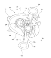
本発明の実施形態による両軸受リール10は、図1から図5に示すように、ベイトキャスト用の両軸受リールである。このリールは、リール本体11と、リール本体11の側方に配置されたスプール回転駆動用ハンドル12と、ハンドル12のリール本体11側に配置されたドラグ調整用のスタードラグ13と、糸巻用のスプール14と、スプール14が装着されるスプール軸20と、を備えている。
<First Embodiment>
1. Overall Configuration of Reel A
ハンドル12は、アーム部12aと、アーム部12aの両端に回転自在に装着された把手12bとを、有するダブルハンドル形のものである。アーム部12aは、図5に示すように、駆動軸30の先端に回転不能に装着されており、ナット28により駆動軸30に締結されている。ハンドル12は後述する第2側カバー16b側に配置される。
The
2.リール本体の構成
図4及び図5に示すように、リール本体11は、たとえばマグネシウム合金などの軽金属製の部材であり、フレーム15と、フレーム15の両側方に装着された第1側カバー16a及び第2側カバー16bと、軸支持部35と、を有している。リール本体11の内部には、スプール14が、スプール軸20を介して、回転自在に装着されている。図5に示すように、第1側カバー16aは、第1側板15aに着脱可能に装着され、第1側板15aの外側を覆う。第2側カバー16bは、第2側板15bにネジ止め固定され、第2側板15bの外側を覆う。
2. Configuration of Reel Body As shown in FIGS. 4 and 5, the
図1から図5に示すように、フレーム15内には、スプール14と、サミングを行う場合の親指の当てとなるクラッチ操作部材17と、スプール14内に均一に釣り糸を巻くためのレベルワインド機構18とが、配置されている。
As shown in FIGS. 1 to 5, a
また、図4及び図5に示すように、フレーム15と第2側カバー16bとの間には、ギア機構19と、クラッチ機構21と、クラッチ制御機構22と、ドラグ機構23と、キャスティングコントロール機構24と、が配置されている。ギア機構19は、ハンドル12からの回転力をスプール14及びレベルワインド機構18に伝えるために設けられる。クラッチ機構21は、スプール14とハンドル12とを連結及び遮断するために設けられる。クラッチ制御機構22は、クラッチ操作部材17の操作に応じてクラッチ機構21を制御するために設けられる。
As shown in FIGS. 4 and 5, between the
ドラグ機構23は、スプール14の糸繰り出し方向の回転を制動するために設けられる。キャスティングコントロール機構24は、スプール14の回転時の抵抗力を調整するために設けられる。また、フレーム15と第1側カバー16aとの間には、キャスティング時のバックラッシュを抑えるための遠心力を用いたスプール制動装置25が、配置されている。
The
図4及び図5に示すように、フレーム15は、第1側板15aと、第1側板15aと所定の間隔をあけて互いに対向するように配置された第2側板15bと、第1側板15a及び第2側板15bを前後及び下部で一体に連結する複数(例えば、3個)の連結部15cとを、有している。下側の連結部15cには、釣り竿を装着するための釣り竿装着部15dが、一体に形成される。第1側板15aは、中央部にスプール軸20の軸芯Cを中心として円形に形成された開口部15eを有する。開口部15eには、軸支持部35が着脱可能に連結される。
As shown in FIGS. 4 and 5, the
スプール14は、図4から図6に示すように、第1側板15aと第2側板15bとの間に設けられる。スプール14は、リール本体11に回転自在に支持される。スプール14は、両側部に皿状のフランジ部14aを有しており、両フランジ部14aの間に筒状の糸巻胴部14bを、有している。スプール14は、糸巻胴部14bの内周側を貫通するスプール軸20に、一体回転可能に固定されている。例えば、スプール14は、セレーション結合により、スプール軸20に一体回転可能に固定されている。
As shown in FIGS. 4 to 6, the
スプール軸20は、たとえばSUS304等の非磁性金属製である。スプール軸20は、図5に示すように、第2側板15bを貫通して第2側カバー16bの外方に延びている。スプール軸20の一端(図5左端)は、軸受38aを介して、軸受収納部35aに回転自在に支持される。スプール軸20の第2側カバー16bの外方に延びる他端(図5右端)は、軸受38bにより、第2側カバー16bに形成されたボス部16dに、回転自在に支持されている。スプール軸20の軸方向の中間部には、大径部20aが形成されている。大径部20aが第2側板15bを貫通する部分には、クラッチ機構21を構成するクラッチピン21aが、径方向に沿って貫通して設けられる。クラッチピン21aは、両端がスプール軸20の外周面に突出する。
The
クラッチ操作部材17は、図1に示すように、第1側板15a及び第2側板15bの間の後部でスプール14後方に配置されている。クラッチ操作部材17は、クラッチ制御機構22に連結されている。クラッチ操作部材17は、第1側板15a及び第2側板15bの間で上下方向にスライド可能である。このクラッチ操作部材17のスライドによって、クラッチ機構21が、連結状態と遮断状態とに切り換えられる。クラッチ操作部材17は、第1側板15aにおいてスプール14側に設けられたガイド軸(図示しない)によって、釣り竿装着部15dと接近及び離反する上下方向に案内される。
As shown in FIG. 1, the
ギア機構19は、図5に示すように、駆動軸30と、駆動軸30に固定された駆動ギア31と、駆動ギア31に噛み合う筒状のピニオンギア32とを、有している。駆動軸30は、第2側板15b及び第2側カバー16bに、回転自在に装着されている。駆動軸30は、ローラ型のワンウェイクラッチ50により、糸繰り出し方向の回転(逆転)が禁止されている。ワンウェイクラッチ50は、第2側カバー16bと駆動軸30との間に、装着されている。駆動ギア31は、駆動軸30に回転自在に装着されており、駆動軸30とドラグ機構23を介して連結されている。
As shown in FIG. 5, the
ピニオンギア32は、第2側板15bを貫通して、スプール軸方向に延びる。ピニオンギア32は、中心にスプール軸20が貫通する筒状部材である。ピニオンギア32は、第2側板15b及び第2側カバー16bに、軸受52及び軸受54によって回転自在かつ軸方向に移動自在に装着されている。ピニオンギア32の一端(図5左端)には、クラッチピン21aに係合する係合溝32aが、形成されている。このピニオンギア32とクラッチピン21aによって、クラッチ機構21が構成される。ピニオンギア32は、クラッチ制御機構22によって、図5のスプール軸20の軸芯Cの上側に示すクラッチオン位置と、軸芯Cの下側に示すクラッチオフ位置と、に移動させられる。
The
クラッチ制御機構22は、図4に示すように、ピニオンギア32をスプール軸20方向に沿って移動させるクラッチヨーク45を、有している。クラッチ操作部材17がクラッチオフ位置に操作されると、クラッチヨーク45は、ピニオンギア32をクラッチオフ位置に移動させる。また、クラッチ制御機構22は、スプール14の糸巻き取り方向の回転に連動してクラッチ機構21をクラッチオンさせる図示しないクラッチ戻し機構を、有している。
As shown in FIG. 4, the clutch control mechanism 22 has a
3.スプール制動機構
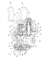
スプール制動装置25は、遠心力によってスプール14を制動するためのものである。スプール制動装置25は、スプール軸20及び軸支持部35に装着されている。スプール制動装置25は、図4から図12に示すように、ブレーキドラム66と、回転部材62と、複数(例えば、6個)のブレーキシュー64と、選択固定部材67と、移動機構68とを、備えている。
3. Spool braking mechanism The
3−1.ブレーキドラム
図4から図6に示すように、ブレーキドラム66は、ブレーキシュー64の径方向外方に配置される。ブレーキドラム66は、揺動するブレーキシュー64に接触可能である。具体的には、ブレーキドラム66の少なくとも一部は、ブレーキシュー64に対して、径方向外方に配置される。より具体的には、ブレーキドラム66は、スプール14に向かって傾斜したテーパ形状の内周面66a(テーパ面)を、有している(図6を参照)。テーパ面66aは、ブレーキシュー64の径方向外方において、ブレーキドラム66の内周面に形成されている。テーパ面66aは、スプール14に向かって縮径している。このテーパ面66aは、揺動するブレーキシュー64に接触する。
3-1. Brake Drum As shown in FIGS. 4 to 6, the
3−2.回転部材
回転部材62は、例えば、ポリアミド樹脂、ポリアセタール樹脂等の合成樹脂製の概ね円形の部材である。回転部材62は、スプール14の糸繰り出し方向の回転、例えばスプール14の回転に連動して、回転する。回転部材62は、スプール軸20に圧入等の適宜の固定手段により一体回転可能に連結されている。
3-2. Rotating member The rotating
図7に示すように、回転部材62は、内周部がスプール軸20に固定されるボス部62aと、ボス部62aの径方向外方に配置された厚肉環状のシュー取付部62bと、ボス部62aとシュー取付部62bとを接続する接続部62cと、を有している。
As shown in FIG. 7, the rotating
ボス部62aは、スプール軸20が貫通する段付きの貫通孔(図示しない)を有する筒状の部分である。貫通孔は、スプール軸20に位置決めされる。ボス部62aは、位置決め凹部69aを有している。具体的には、位置決め凹部69aが、ボス部62aの外周面に形成されている。より具体的には、3個の位置決め凹部69aが、互いに所定の間隔を隔てて、ボス部62aの外周部に形成されている。位置決め凹部69aと、後述する位置決め凸部69bとは、位置決め構造69を構成している。なお、位置決め構造69は、選択固定部材67を位置決めするための構造である。
The
図7及び図8に示すように、シュー取付部62bは、本体部63aと、本体部63aに設けられた複数(例えば、6個)のシュー支持凹部63bと、シュー支持凹部63bに設けられた複数(例えば、6個)の揺動軸部63cとを、有している。
As shown in FIGS. 7 and 8, the
本体部63aは、接続部62cの外周部に一体に形成されている。本体部63a(シュー支持凹部63bを除く)は、実質的に円筒状に形成されている。本体部63aの内周部には、選択固定部材67(後述する案内凸部87c)を回転方向に案内する案内凹部63dが、形成されている(図8を参照)。案内凹部63dは、回転方向(円周方向)に延びる溝部である。
The
シュー支持凹部63bは、周方向に間隔を隔てて設けられている。シュー支持凹部63bは、スプール14の回転方向に等間隔に配置されている。シュー支持凹部63bは、ブレーキシュー64を配置可能な幅で、凹んで形成されている。図8に示すように、揺動軸部63cは、ブレーキシュー64を、揺動可能に支持する。揺動軸部63cは、スプール軸20と食い違う方向に延びており、シュー支持凹部63bに一体に形成されている。揺動軸部63cは、円柱形状に形成されている。
The shoe support recesses 63b are provided at intervals in the circumferential direction. The shoe support recesses 63 b are arranged at equal intervals in the rotation direction of the
図7に示すように、接続部62cは、厚肉円板状の部材であり、ボス部62aの外周部に一体に形成されている。接続部62cの外周側には、シュー取付部62bの本体部63aが、一体に形成されている。
As shown in FIG. 7, the
3−3.ブレーキシュー
ブレーキシュー64は、例えば、ポリアミド樹脂等の弾性を有する合成樹脂製の部材である。図7及び図8に示すように、ブレーキシュー64は、スプール軸20と食い違う軸まわりに揺動可能に、回転部材62に装着される。具体的には、ブレーキシュー64は、回転部材62の揺動軸部63cに揺動可能に装着される。
3-3. Brake shoe The
ブレーキシュー64は、揺動可能状態及び揺動不能状態のいずれか一方の状態で、揺動軸部63cに配置される。より具体的には、揺動可能状態では、ブレーキシュー64は、遠心力によってスプール14を制動可能である。ここで、ブレーキシュー64がスプール14を制動する位置が、制動位置となる(図7を参照)。また、揺動不能状態では、ブレーキシュー64は、スプール14を制動することなく(非制動で)、スプール14の回転を許可する。ここで、ブレーキシュー64がスプール14を制動しない位置が、非制動位置となる(図8を参照)。揺動不能状態は、ブレーキシュー64に選択固定部材67が係合することによって、実現される。ブレーキシュー64と選択固定部材67との係合については、後述する。
The
図8に示すように、ブレーキシュー64は、本体部64aと、揺動軸部63cに装着される装着部64bと、本体部64aに接触して本体部64aをブレ止めするためのブレ止め部64cとを、有している。本体部64aは、第1端65aと、第1端65aと逆側の第2端65bと、を有している。本体部64aは、第1端65aから第2端65bに向かって長い部材である。第1端65aには、ブレーキドラム66に接触する接触部65fが、形成されている。接触部65fは、円弧状に形成されている。
As shown in FIG. 8, the
また、本体部64aは、一対のボス部65gを、有している。ボス部65gは、本体部64aから外方に突出するように、本体部64aに一体に形成されている。ボス部65gは、本体部64aとシュー支持凹部63bの壁部との間に配置され、回転部材62のシュー支持凹部63bの壁部に摺動可能である。
Further, the
装着部64bは、ブレーキシュー64が揺動軸部63cに装着される部分である。装着部64bは、第2端65bと重心Gとの間において、本体部64aに設けられている。装着部64bは、C字形状の装着凹部65cと、被係合部65dとを、有している。
The mounting
装着凹部65cは、揺動軸部63cに嵌合される。例えば、装着凹部65cは、揺動軸部63cにすきま嵌めで嵌合される。装着凹部65cの開口部は、揺動軸部63cの径より狭い幅に、形成されている。被係合部65dは、選択固定部材67に係合する。詳細には、被係合部65dは、後述する選択固定部材67の係合部67bに当接する。
The mounting
ブレ止め部64cは、本体部64aから外方に突出して、本体部64aに一体に形成されている。詳細には、2個のブレ止め部64cが、本体部64aの両側に一体に形成されている。ブレ止め部64cは、シュー取付部62bの本体部63aに摺動可能である。ブレ止め部64cは、シュー取付部62bの本体部63aに摺動可能である。
The
上記のような構成を有するブレーキシュー64は、スプール14が回転すると、重心Gに作用する遠心力により、揺動軸芯Pを中心として揺動する。
When the
なお、図9から図11では、6個のブレーキシュー64において径方向に互いに対向する3組のブレーキシュー64それぞれを、第1ブレーキシュー164a、第2ブレーキシュー164b、第3ブレーキシュー164cと記している。第1ブレーキシュー164a、第2ブレーキシュー164b、及び第3ブレーキシュー164cそれぞれの構成は、上述の構成と同様である。
In FIG. 9 to FIG. 11, the three
3−4.選択固定部材
図7及び図8に示すように、選択固定部材67は、回転部材62に装着される。本実施例においては、選択固定部材67は、回転部材62に対して、回転可能に装着されている。選択固定部材67は、ブレーキシュー64に選択的に係合可能である。例えば、選択固定部材67は、第1ブレーキシュー164a及び第2ブレーキシュー164bの少なくともいずれか一方に、選択的に係合する。選択固定部材67は、ブレーキシュー64(第1ブレーキシュー164a及び/又は第2ブレーキシュー164b)に係合した場合、このブレーキシュー64を非制動位置で固定する。
3-4. Selection Fixing Member As shown in FIGS. 7 and 8, the
図8及び図12に示すように、選択固定部材67は、本体部67aと、係合部67bと、位置決め凸部69bと、サポート部67cとを、有している。本体部67aは、回転部材62に回転自在に装着される。本体部67aは、シュー取付部62bの内周側に配置される。本体部67aは、円環状に形成されている。
As shown in FIGS. 8 and 12, the selective fixing
係合部67bは、本体部67aに設けられている。詳細には、係合部67bは、本体部67aの外周部に設けられている。より詳細は、複数(例えば、4個)の係合部67bが、互いに間隔を隔てて、本体部67aの外周部に設けられている。係合部67bは、第1ブレーキシュー164a及び第2ブレーキシュー164bの少なくともいずれか一方に、選択的に係合可能である。係合部67bは、回転部材62に対する回転量に応じて、第1ブレーキシュー164a及び第2ブレーキシュー164bの少なくともいずれか一方に、選択的に係合可能である。
The
図12では、4個の係合部67bにおいて径方向に互いに対向する2組の係合部67bそれぞれが、第1係合部167b及び第2係合部267bと記されている。また、図12では、以下に示す第1係合部167b及び第2係合部267bの詳細説明の符号が、1個の第1係合部167b及び1個の第2係合部267bにだけ付されている。
In FIG. 12, in the four
図9は、2個の第1ブレーキシュー164a、2個の第2ブレーキシュー164b、及び2個の第3ブレーキシュー164c(6個のブレーキシュー64)が揺動可能である状態を、示している。すなわち、この状態では、2個の第1係合部167b及び2個の第2係合部267b(4個の係合部67b)は、第1ブレーキシュー164a、第2ブレーキシュー164b、及び第3ブレーキシュー164cに非係合である。
FIG. 9 shows a state where the two
図10に示すように、第1係合部167bは、所定の第1回転角度α1において、第1ブレーキシュー164aに、係合可能である。また、図11に示すように、所定の第2回転角度α2において、第1係合部167bは第1ブレーキシュー164aに係合可能であり、第2係合部267bは第2ブレーキシュー164bに係合可能である。図12に示すように、本体部67aの外周部における円周方向(回転部材が回転する方向)において、第1係合部167bが第2係合部267bより長くなるように、第1係合部167bは本体部67aに一体に形成されている。
As shown in FIG. 10, the
図12に示すように、第1係合部167bは、第1シュー案内部87a(案内部の一例)と、第1当接部87bと、案内凸部87cとを、有している。第1シュー案内部87aは、ブレーキシュー64を非制動位置へと案内する部分である。第1シュー案内部87aは、テーパ状に形成されている。なお、本実施例においては、一対の第1シュー案内部87aは、第1係合部167bにおける円周方向の両端部に形成されているが、ブレーキシュー64に接する一端部にだけ形成されていてもよい。
As shown in FIG. 12, the
図12に示すように、第1当接部87bは、ブレーキシュー64に当接(係合)する部分である。図12に示すように、第1当接部87bは、第1係合部167bにおける円周方向の中央部に形成されている。言い換えると、第1当接部87bは、一対の第1シュー案内部87aの間において、第1係合部167bに形成されている。図8に示すように、第1当接部87bは、ブレーキシュー64の被係合部65dに当接し、ブレーキシュー64を半径方向に押圧する。これにより、ブレーキシュー64が、非制動位置に位置決めされる。
As shown in FIG. 12, the
図8及び図12に示すように、案内凸部87cは、回転部材62に係合して回転方向に案内される部分である。案内凸部87cは、第1シュー案内部87aの外周部から外方に突出して形成されている。案内凸部87cは、回転部材62の案内凹部63d(溝部)に係合して、回転方向(円周方向)に移動可能である。すなわち、案内凸部87cが案内凹部63dに案内されることによって、選択固定部材67は安定的に回転可能である。
As shown in FIGS. 8 and 12, the guide
図12に示すように、第2係合部267bは、第2ブレーキシュー164bに、係合可能である。具体的には、図11に示すように、第2係合部267bは、所定の第2回転角度α2において、第2ブレーキシュー164bに、係合可能である。より具体的には、所定の第2回転角度α2では、第1係合部167bが第1ブレーキシュー164aに係合し、第2係合部267bが第2ブレーキシュー164bに係合する。
As shown in FIG. 12, the
第2係合部267bは、第2シュー案内部88a(案内部の一例)と、第2当接部88bとを、有している。第2シュー案内部88aは、ブレーキシュー64を非制動位置へと案内する部分である。第2シュー案内部88aは、テーパ状に形成されている。なお、本実施例においては、一対の第2シュー案内部88aは、第2係合部267bにおける円周方向の両端部に形成されているが、ブレーキシューに接する一端部にだけ形成されていてもよい。
The
第2当接部88bは、ブレーキシューに当接(係合)する部分である。図12に示すように、第2当接部88bは、第2係合部267bにおける円周方向の中央部に形成されている。言い換えると、第2当接部88bは、一対の第2シュー案内部88aの間において、第2係合部267bに形成されている。図8に示すように、第2当接部88bは、ブレーキシュー64の被係合部65dに当接し、ブレーキシュー64を半径方向に押圧する。これにより、ブレーキシュー64が、非制動位置に位置決めされる。
The
図9から図12に示すように、位置決め凸部69bは、本体部67aの内周部に形成されている。具体的には、位置決め凸部69bは、本体部67aの内周部から内方に突出して、本体部67aに一体に形成されている。位置決め凸部69bの先端部は、ボス部62aに形成された3個の位置決め凹部69aのいずれか1つに、係合する。これにより、選択固定部材67が、回転部材62に対して位置決めされる。このように、選択固定部材67の位置決め凸部69bと、回転部材62の位置決め凹部69aとによって、位置決め構造69が構成されている。
As shown in FIGS. 9 to 12, the positioning
図12に示すように、サポート部67cは、本体部67aの内周部に形成されている。具体的には、サポート部67cは、本体部67aの内周部から内方に突出して、本体部67aに一体に形成されている。図9から図11に示すように、サポート部67cの先端部は、ボス部62aの外周部に当接し、ボス部62aの外周部に沿って摺動可能である。ここでは、複数(2個)のサポート部67cが、本体部67aに一体に形成されている。このサポート部67cによって、本体部67aを安定的に回転させることができる。また、このサポート部67cによって、本体部67aの内方への変形を規制することができる。
As shown in FIG. 12, the
3−5.移動機構
移動機構68は、ブレーキシュー64とブレーキドラム66とを、スプール軸20の軸方向に、相対移動可能かつ位置決め可能である。移動機構68は、図3から図6に示すように、操作部材60と、ブレーキカム71(図4参照)と、第1ギア部材73(図6参照)と、第1ギア部材73に噛み合う第2ギア部材74と、を有している。
3-5. Moving Mechanism The moving
操作部材60は、例えば合成樹脂製の円形のつまみであり、第1側カバー16aに形成された開口部16cによって第1側カバー16aから外部に露出する。操作部材60は、軸支持部35の底部35cの外側面にねじ込まれるねじ軸78によって、回動自在に支持される。操作部材60は、位置決め機構76によって複数(たとえば、40段階程度)に位置決めされる。第1ギア部材73は、操作部材60と一体形成される。第2ギア部材74は、ブレーキドラム66に一体回動可能に連結される。
The
図4に示すように、ブレーキドラム66は、軸支持部35に、ブレーキカム71を介して係合する。ブレーキカム71は、軸支持部35の外周面に回転不能に固定されている。ブレーキカム71は、螺旋状のカム溝71aを有している。ブレーキカム71(カム溝71a)は、ブレーキドラム66の内周面に突出して形成された、例えば複数のカム突起66cに、係合する。これにより、操作部材60が一方向に回動操作されると、ブレーキドラム66がスプール14に接近する方向に移動して制動力が徐々に強くなる。また、操作部材が他方向に回動操作されると、ブレーキドラム66がスプール14から離反する方向に移動し、制動力が徐々に弱くなる。
As shown in FIG. 4, the
4.スプール制動装置の動作
4−1.スプール制動装置の動作概要
スプール制動装置25では、操作部材60が操作開始位置にあるときは、ブレーキシュー64の接触部65fは、ブレーキドラム66のテーパ面66aの小径側に接触する。このとき、ブレーキシュー64の揺動角度が最も小さくなり、ブレーキドラム66がブレーキシュー64を押圧する押圧力も、最も小さくなる。これにより、スプール14に作用する制動力は、最も小さい。
4). Operation of spool braking device 4-1. Outline of Operation of Spool Braking Device In the
操作部材60が操作開始位置から回動操作されると、第1ギア部材73が回転する。すると、第1ギア部材73に噛み合う第2ギア部材74が、回転し、ブレーキドラム66も回動する。すると、ブレーキドラム66は、ブレーキカム71を介して、スプール14に接近する方向に移動する。このとき、ブレーキシュー64の接触部65fは、テーパ面66aの大径側に接触する。ブレーキドラム66がスプール14に接近するにつれて、ブレーキシュー64の揺動角度が徐々に大きくなる。すると、ブレーキドラム66がブレーキシュー64を押圧する押圧力は、徐々に大きくなる。これにより、スプール14に作用する制動力は、徐々に大きくなる。
When the
そして、操作部材60が最大制動位置に設定されると、ブレーキシュー64の揺動角度が最も大きくなり、ブレーキドラム66がブレーキシュー64を押圧する押圧力が、最大になる。これにより、スプール14に作用する制動力は、最も大きくなる。
When the
なお、操作部材60を最大制動位置から操作開始位置に向けて操作する場合は、上記とは反対に、制動力が徐々に弱くなる。
Note that when the
4−2.ブレーキシューの設定及び動作
6個のブレーキシュー64それぞれは、選択固定部材67の回転量(回転角度)によって、揺動可能状態と揺動不能状態とに設定可能である。
4-2. Setting and Operation of Brake Shoe Each of the six
図9に示したように、4個の係合部67b(第1係合部167b及び第2係合部267b)が、6個のブレーキシュー64(第1ブレーキシュー164a、第2ブレーキシュー164b、及び第3ブレーキシュー164c)に非係合である場合、6個のブレーキシュー64は揺動可能である。
As shown in FIG. 9, the four
このように、6個のブレーキシュー64が揺動可能状態である場合において、スプール14の回転に連動して、回転部材62が回転すると、遠心力によって、6個のブレーキシュー64は揺動する。詳細には、回転部材62が回転すると、6個のブレーキシュー64が揺動軸部63cまわりに揺動する。すると、各ブレーキシュー64の第1端65aの接触部65fが、ブレーキドラム66のテーパ面66aに接触して、スプール14の回転が制動される。
Thus, when the six
ここで、ユーザが選択固定部材67を所定の第1回転角度α1に設定すると(図10を参照)、選択固定部材67の第1係合部167bが、第1ブレーキシュー164aに係合する。詳細には、選択固定部材67の第1係合部167bに形成された第1シュー案内部87aによって、第1ブレーキシュー164aが案内される。すると、第1ブレーキシュー164aの第2端65bが、選択固定部材67の第1係合部167bに形成された第1当接部87bに、当接する。このようにして、第1ブレーキシュー164aが、選択固定部材67の第1係合部167bによって、非制動位置において固定される。
Here, when the user sets the
この状態では、2個の第1ブレーキシュー164aは揺動不能であり、2個の第2ブレーキシュー164b及び2個の第3ブレーキシュー164cは揺動可能である。すなわち、この状態で回転部材62が回転すると、2個の第2ブレーキシュー164b及び2個の第3ブレーキシュー164cを含む4個のブレーキシュー64が、揺動して、スプール14の回転が制動される。
In this state, the two
このように、ユーザが選択固定部材67を所定の第1回転角度α1に設定することによって、6個のブレーキシュー64(第1ブレーキシュー164a、第2ブレーキシュー164b、及び第3ブレーキシュー164c)が揺動可能である状態から、4個のブレーキシュー64(第2ブレーキシュー164b及び第3ブレーキシュー164c)が揺動可能である状態(図9の状態から図10の状態)へと、ブレーキシュー64の状態が移行する。
In this way, the user sets the selective fixing
次に、回転部材62が静止している状態で、ユーザが選択固定部材67を所定の第2回転角度α2(>第1回転角度α1)に設定すると(図11を参照)、選択固定部材67の第2係合部267bが、第2ブレーキシュー164bに係合する。詳細には、選択固定部材67の第2係合部267bに形成された第2シュー案内部88aによって、第2ブレーキシュー164bが案内される。すると、第2ブレーキシュー164bの第2端65bが、選択固定部材67の第2係合部267bに形成された第2当接部88bに、当接する。このようにして、第2ブレーキシュー164bが、選択固定部材67の第2係合部267bによって、非制動位置において固定される。
Next, when the user sets the
ここで、図11に示したように、第2ブレーキシュー164bが、選択固定部材67の第2係合部267bによって固定された状態では、第1ブレーキシュー164aも、選択固定部材67の第1係合部167bによって固定されている。すなわち、この状態では、2個の第1ブレーキシュー164a及び2個の第2ブレーキシュー164bは揺動不能であり、2個の第3ブレーキシュー164cは揺動可能である。この状態で回転部材62が回転すると、2個の第3ブレーキシュー164cだけが揺動して、スプール14の回転が制動される。
Here, as shown in FIG. 11, when the
このように、選択固定部材67を回転させることによって、第1ブレーキシュー164a及び第2ブレーキシュー164bの少なくともいずれか1つが、任意に揺動不能に選択固定される。すなわち、選択固定部材67の回転によって、スプール14の回転に与える制動力を、任意に調整することができる。
As described above, by rotating the selective fixing
5.特徴
(A1)本スプール制動装置25では、選択固定部材67を動作させることによって、ブレーキシュー64を、選択的に固定し、制動位置において作動不能にすることができる。また、選択固定部材67を動作させることによって、ブレーキシュー64を、選択的に動作させ、非制動位置において作動可能にすることができる。すなわち、本スプール制動装置25では、選択固定部材67によって、ブレーキシュー64の作動可能状態と作動不能状態とを、容易に設定することができる。
5. Features (A1) In the
具体的には、ブレーキシュー64の数が多くなっても、選択固定部材67だけで、ブレーキシュー64を容易に固定することができる。また、ブレーキシュー64が小型の部材であっても、選択固定部材67だけで、ブレーキシュー64を容易に選択することができる。さらに、選択固定部材67をブレーキシュー64に係合することによって、ブレーキシュー64を回転部材62に確実に固定することができる。
Specifically, even if the number of
(A2)本スプール制動装置25では、回転部材62に対して選択固定部材67を回転させることによって、ブレーキシュー64を容易に選択的に固定することができる。言い換えると、回転部材62に対して選択固定部材67を回転させることによって、ブレーキシュー64の固定を、容易に解除することができる。
(A2) In the
(A3)本スプール制動装置25では、選択固定部材67の係合部67bを、第1ブレーキシュー164a及び第2ブレーキシュー164bの少なくともいずれか一方に、選択的に係合することによって、ブレーキシュー64を容易に作動不能にすることができる。また、選択固定部材67の係合部67bを、第1ブレーキシュー164a及び第2ブレーキシュー164bの少なくともいずれか一方に、非係合にすることによって、ブレーキシュー64を容易に作動可能にすることができる。
(A3) In the
(A4)本スプール制動装置25では、位置決め構造69を有しているので、この位置決め構造69によって、選択固定部材67を容易に位置決めすることができる。すなわち、選択固定部材67をブレーキシュー64に係合させた状態を、確実に保持することができる。
(A4) Since the
(A5)本スプール制動装置25では、位置決め構造69を有している。位置決め構造69は、位置決め凹部69aと、位置決め凸部69bとを、有している。位置決め凸部69bを位置決め凹部69aに係合することによって、選択固定部材67を容易に位置決めすることができる。すなわち、選択固定部材67をブレーキシュー64に係合させた状態を、確実に保持することができる。
(A5) The
(A6)本スプール制動装置25では、係合部67bが、ブレーキシュー64を非制動位置に案内する案内部を、有しているので、選択固定部材67を動作させた場合に、係合部67bをブレーキシュー64に容易に係合させることができる。
(A6) In the
(A7)本スプール制動装置25では、選択固定部材67が第1ブレーキシュー164aに係合すると、第1ブレーキシュー164aが非制動位置において固定される。また、選択固定部材67が第2ブレーキシュー164bに係合すると、第2ブレーキシュー164bが非制動位置において固定される。さらに、選択固定部材67が、第1ブレーキシュー164a及び第2ブレーキシュー164bに係合すると、第1ブレーキシュー164a及び第2ブレーキシュー164bが非制動位置において固定される。すなわち、これらの場合では、ブレーキシュー64は、非制動位置において、作動不能である。一方で、選択固定部材67が非係合であるブレーキシュー64は、制動位置において、作動可能である。このように、本スプール制動装置25では、選択固定部材67によって、ブレーキシュー64の作動可能状態と作動不能状態とを、容易に設定することができる。
(A7) In the
(A8)本スプール制動装置25では、係合部67b(第1係合部167b、第2係合部267b)を、第1ブレーキシュー164a及び第2ブレーキシュー164bに個別に係合させることによって、ブレーキシュー64を容易に作動不能にすることができる。係合部67b(第1係合部167b、第2係合部267b)とブレーキシュー64(第1ブレーキシュー164a・第2ブレーキシュー164b)との係合を解除することによって、ブレーキシュー64を容易に作動可能にすることができる。
(A8) In the
(A9)本スプール制動装置25では、1つの係合部67b(第1係合部167b)によって、2つのブレーキシュー64(第1ブレーキシュー164a・第2ブレーキシュー164b)を同時に、作動不能に固定することができる。これにより、状況に応じて、2つの係合部67b(第1係合部167b、第2係合部267b)を、第1ブレーキシュー164a及び第2ブレーキシュー164bに個別に係合させたり、1つの係合部67b(第1係合部167b)だけで、第1ブレーキシュー164a及び第2ブレーキシュー164bの両方を同時に係合させたりすることができる。
(A9) In the
(A10)本スプール制動装置25では、第1係合部167bが、第2係合部267bより長く形成されているので、例えば、第1係合部167bを第1ブレーキシュー164aに係合させた状態において、選択固定部材67を回転させたとしても、第1係合部167bと第1ブレーキシュー164aとの係合を維持した状態で、第2係合部267bを第2ブレーキシュー164bに係合させることができる。
6.他の実施形態
(a1)前記第1実施形態では、選択固定部材67を回転させることによって、ブレーキシュー64を揺動不能に固定する場合の例を、示した。これに代えて、以下に示すように、選択固定部材167を、回転部材62の回転軸に沿う方向に移動させることによって、ブレーキシュー64を揺動不能に固定するようにしてもよい。
(A10) In the
6). Other Embodiments (a1) In the first embodiment, an example in which the
この場合、例えば、図13に示すように、選択固定部材167は、半径方向において、シュー取付部62bとボス部62aとの間に配置される。この状態で、選択固定部材167は、回転部材62の回転軸に沿う方向に移動可能である。
In this case, for example, as shown in FIG. 13, the
具体的には、選択固定部材167を接続部62cに当接させた状態(図示しない)では、全てのブレーキシュー64は揺動可能である。この状態から、選択固定部材167を第1移動量M1だけ回転部材62の回転軸に沿う方向に移動させると、図13に示すように、第1係合部167bが第1ブレーキシュー164aの被係合部65dに当接する。これにより、第1ブレーキシュー164aが揺動不能になる。
Specifically, in a state where the
この状態では、選択固定部材167の第2係合部267bと、第1ブレーキシュー164aの被係合部65dとの間には、隙間が形成されている。このため、第2ブレーキシュー164bは、揺動可能である。また、第3ブレーキシュー164cも、揺動可能である。
In this state, a gap is formed between the second
さらに、この状態から、選択固定部材167を第2移動量M2(>第1移動量M1)で回転部材62の回転軸に沿う方向に移動させると、第2係合部267bが第2ブレーキシュー164bの被係合部65dに当接する。これにより、第2ブレーキシュー164bも揺動不能になる。この状態では、第3ブレーキシュー164cが、揺動可能である。
Furthermore, when the
このように、選択固定部材67を移動させることによって、第1ブレーキシュー164a及び第2ブレーキシュー164bの少なくともいずれか1つが、任意に揺動不能に固定される。すなわち、選択固定部材67の移動によって、スプール14の回転に与える制動力を、任意に調整することができる。
In this way, by moving the selective fixing
(a2)前記第1実施形態及び(a1)の他の実施形態では、第1係合部167b及び第2係合部267bによって、第1ブレーキシュー164a及び第2ブレーキシュー164bを揺動不能に固定する場合の例を、示した。これに加えて、選択固定部材67に第3係合部(図示しない)を形成して、選択固定部材67の所定の回転量又は所定の移動量において、第3係合部を第3ブレーキシュー164cに係合させてもよい。この構成では、第1ブレーキシュー164a、第2ブレーキシュー164b、及び第3ブレーキシュー164cの少なくともいずれか1つを、任意に揺動不能に固定することができる。これにより、全てのブレーキシューを非制動位置において固定することができる。なお、ここで設定される所定の回転量は、第1回転角度α1及び/又は第2回転角度α2と、同じであっても異なっていてもよい。
(A2) In the first embodiment and the other embodiments of (a1), the
<第2実施形態>
第2実施形態の両軸受リールの構成は、主に、第1実施形態における、ブレーキシュー64の構成、回転部材62の構成、及び選択固定部材67の構成を除いて、第1実施形態と同様である。このため、ここでは、第1実施形態と同様の構成については、説明を省略し、第1実施形態と同じ符号を用いて説明する。また、第2実施形態を説明するための図14及び図15では、第1実施形態と同様の構成については、同じ符号を付している。また、ここで省略した説明は第1実施形態の説明に準ずる。
Second Embodiment
The configuration of the dual-bearing reel of the second embodiment is mainly the same as that of the first embodiment except for the configuration of the
1.スプール制動機構
スプール制動装置225は、遠心力によってスプール14を制動するためのものである。スプール制動装置225は、スプール軸20及び軸支持部35に装着されている。スプール制動装置225は、図14及び図15に示すように、ブレーキドラム66と、回転部材262と、複数(例えば、4個)のブレーキシュー264と、選択固定部材267と、移動機構68とを、備えている。なお、上述したように、以下では、ブレーキドラム66及び移動機構68については、説明を省略する。
1. Spool braking mechanism The
回転部材262は、スプール14の糸繰り出し方向の回転、例えばスプール14の回転に連動して、回転する。回転部材262は、スプール軸20に圧入等の適宜の固定手段により一体回転可能に連結されている。
The rotating
図14に示すように、回転部材262は、内周部がスプール軸20に固定されるボス部262aと、ボス部262aの径方向外方に配置されたシュー取付部262bと、ボス部262aとシュー取付部262bとを接続する接続部262cと、を有している。
As shown in FIG. 14, the rotating
ボス部262aは、スプール軸20が貫通する段付きの貫通孔(図示しない)を有する筒状の部分である。貫通孔は、スプール軸20に位置決めされる。
The
シュー取付部262bは、接続部262cの外周部に一体に形成されている。シュー取付部262bは、ブレーキシュー264を配置するための凹部89aを有している。凹部89aには、回転部材262の回転軸K2(図15を参照)を基準として、外方に開口している。凹部89aの底部には、ブレーキシュー264を案内するガイド軸89bが、設けられている。ガイド軸89bは、ブレーキシュー264を、制動位置と非制動位置との間で移動可能に保持する。凹部89aの壁部には、互いに対向する一対の突出部89cが、設けられている。一対の突出部89cは、ブレーキシュー264を制動位置において保持する。
The
接続部262cは、厚肉円板状の部材であり、ボス部262aの外周部に一体に形成されている。接続部262cの外周側には、シュー取付部262bが、一体に形成されている。
The
ブレーキシュー264は、遠心力によってスプール14を制動する制動位置、及びスプール14の回転を非制動で許可する非制動位置の間を移動可能に、回転部材262に支持されている。具体的には、ブレーキシュー264は、回転部材262のガイド軸89bに対して、半径方向に進退自在に装着されている。
The
ブレーキシュー264は、本体部364aと、本体部364aに設けられた鍔部364cとを、有している。本体部364aには、ブレーキドラム66に接触する接触部265fが、形成されている。また、本体部364aには、孔部265cが形成されている。孔部265cは、シュー取付部262bのガイド軸89bに、挿通される。
The
鍔部364cは、本体部364aの外周部に一体に形成されている。鍔部364cは、本体部364aの外周部から外方に突出している。鍔部364cは、シュー取付部262bの凹部89aの壁部に沿って、移動可能である。鍔部364cは、シュー取付部262bの突出部89cに当接可能である。
The
ブレーキシュー264は、移動可能状態及び移動不能状態のいずれか一方の状態で、ガイド軸89bに配置される。移動可能状態では、ブレーキシュー264は、遠心力によって、スプール14を制動可能である。この場合、ブレーキシュー264に遠心力が作用すると、ブレーキシュー264は、ガイド軸89bに沿って半径方向外方に移動する。すると、ブレーキシュー264の鍔部364cがシュー取付部262bの突出部89cに当接し、ブレーキシュー264が制動位置に配置される。これにより、ブレーキシュー64の本体部364aがブレーキドラム66の内周面に当接し、スプール14が制動される。
The
一方で、移動不能状態では、ブレーキシュー264は、スプール14を制動することなく(非制動で)、スプール14の回転を許可する。移動不能状態は、ブレーキシュー264に選択固定部材267が係合することによって、実現される。この場合、ブレーキシュー264に遠心力が作用すると、ブレーキシュー264の鍔部364cが、選択固定部材267の係合部367b(後述する)に係合する。この状態では、ブレーキシュー264は、ガイド軸89bに沿って移動不能である。この状態が、ブレーキシュー264が非制動位置に配置された状態である。すなわち、ブレーキシュー64の本体部364aは、ブレーキドラム66の内周面に当接不能であり、スプール14は非制動である。
On the other hand, in the immovable state, the
上記の構成を有するブレーキシュー264は、第1ブレーキシュー264a及び第2ブレーキシュー264bを、有している。2個の第1ブレーキシュー264aが半径方向に互いに対向するように、各第1ブレーキシュー264aがシュー取付部262bのガイド軸89bに装着されている。また、2個の第2ブレーキシュー264bが半径方向に互いに対向するように、各第2ブレーキシュー264bがシュー取付部262bのガイド軸89bに装着されている。また、第1ブレーキシュー264a及び第2ブレーキシュー264bは、周方向(回転方向)に所定の間隔を隔てて配置されている。より具体的には、第1ブレーキシュー264aと第2ブレーキシュー264bとは、回転軸K2まわりに互いに90度間隔を隔てて、配置されている。
The
選択固定部材267は、回転部材262に装着される。選択固定部材267が、回転部材262に対して、回転部材262の回転軸K2に沿う方向に、移動可能に装着されている。選択固定部材267は、ブレーキシュー264に選択的に係合可能である。これにより、選択固定部材267は、ブレーキシュー264を非制動位置において選択的に固定する。例えば、選択固定部材267は、第1ブレーキシュー264a及び第2ブレーキシュー264bの少なくともいずれか一方に、選択的に係合する。
The
図15に示すように、選択固定部材267は、本体部267aと、係合部367bとを、有している。本体部267aは、回転部材262に対して移動可能である。本体部267aは、円環状に形成されている。係合部367bは、本体部267aに設けられている。詳細には、複数(例えば、4組)の係合部367bが、互いに間隔を隔てて、本体部267aから外方に突出して一体に形成されている。係合部367bは、第1ブレーキシュー264a及び第2ブレーキシュー264bの少なくともいずれか一方に、選択的に係合可能である。係合部367bは、回転部材262に対する本体部267aの移動量に応じて、第1ブレーキシュー264a及び第2ブレーキシュー264bの少なくともいずれか一方に、選択的に係合する。
As shown in FIG. 15, the
具体的には、4組の係合部367bにおいて径方向に互いに対向する2組の係合部367bそれぞれが、第1係合部467b及び第2係合部567bと記されている。一対の第1係合部467b及び一対の第2係合部567bは、棒状に形成されている。一対の第1係合部467b及び一対の第2係合部567bは、本体部267aに一体に形成されている。回転部材262の回転軸K2に沿う方向において、一対の第1係合部467bは、一対の第2係合部567bより長い。これにより、選択固定部材267が所定の第1移動量で移動した場合、一対の第1係合部467bは、第1ブレーキシュー264aの鍔部364cに係合する。また、選択固定部材267が所定の第2移動量で移動した場合、一対の第2係合部567bは、所定の第2移動量において、第2ブレーキシュー264bの鍔部364cに係合する。
Specifically, in the four sets of engaging
2.ブレーキシューの設定及び動作
4個のブレーキシュー264それぞれは、回転部材262に対する選択固定部材267の移動量に応じて、移動可能状態と移動不能状態とに設定可能である。
2. Setting and Operation of Brake Shoe Each of the four
4個のブレーキシュー264が移動可能状態である場合、スプール14の回転に連動して、回転部材262が回転すると、遠心力によって、4個のブレーキシュー264は、半径方向外方に移動する。詳細には、回転部材262が回転すると、4個のブレーキシュー264が、ガイド軸89bに沿って半径方向外方に移動する。すると、各ブレーキシュー264の接触部265fが、ブレーキドラム66の内周面に接触して、スプール14の回転が制動される。
When the four
ここで、回転部材262が静止している状態で、ユーザが選択固定部材267を回転部材262に向けて押し込むことによって、選択固定部材267が所定の第1移動量に設定されると、図14に示すように、選択固定部材267の第1係合部467bが、第1ブレーキシュー264aに係合する。詳細には、選択固定部材267の第1係合部467bが、第1ブレーキシュー264aの鍔部364cに係合する。言い換えると、第1ブレーキシュー264aの鍔部364cが、第1係合部467bとシュー取付部262bの凹部の底部との間に、配置される。これにより、第1ブレーキシュー264aが、選択固定部材267の第1係合部467bによって、非制動位置において固定される。この状態では、2個の第1ブレーキシュー264aは移動不能であり、2個の第2ブレーキシュー264bは移動可能である。すなわち、この状態で回転部材262が回転すると、2個の第2ブレーキシュー264bが半径方向外方に移動して、スプール14の回転が制動される。
Here, when the
次に、回転部材262が静止している状態で、ユーザが選択固定部材267を回転部材262に向けてさらに押し込むことによって、選択固定部材267が所定の第2移動量(>第1移動量)に設定されると、選択固定部材267の第2係合部567bが、第2ブレーキシュー264bに係合する。
Next, when the
詳細には、選択固定部材267の第2係合部567bが、第2ブレーキシュー264bの鍔部364cに係合する。言い換えると、第2ブレーキシュー264bの鍔部364cが、第2係合部567bとシュー取付部262bの凹部の底部との間に、配置される。これにより、第2ブレーキシュー264bが、選択固定部材267の第2係合部567bによって、非制動位置において固定される。この状態では、全てのブレーキシュー264(2個の第1ブレーキシュー264a及び2個の第2ブレーキシュー264b)は、移動不能である。すなわち、この状態で回転部材262が回転しても、スプール14の回転は制動されない。
Specifically, the
このように、選択固定部材267を移動させることによって、第1ブレーキシュー264a及び/又は第2ブレーキシュー264bが、任意に揺動不能に固定される。すなわち、選択固定部材267の移動によって、スプール14の回転に与える制動力を、容易に調整することができる。
Thus, by moving the
3.特徴
(B1)本スプール制動装置225では、選択固定部材267を回転部材262の回転軸に沿う方向に移動させることによって、ブレーキシュー264を容易に選択的に固定することができる。言い換えると、回転部材262に対して選択固定部材267を上記の回転軸K2に沿う方向に移動させることによって、ブレーキシュー264の固定を、容易に解除することができる。
3. Features (B1) In the
(B2)本スプール制動装置225では、係合部467b,567bは、回転部材262に対する移動量に応じて、第1ブレーキシュー264a及び第2ブレーキシュー264bの少なくともいずれか一方に、選択的に係合可能である。このため、例えば、所定の第1移動量の場合、係合部467b,567bを、第1ブレーキシュー264a及び第2ブレーキシュー264bのいずれか一方に、係合させることができる。また、所定の第2移動量の場合、係合部467b,567bを、第1ブレーキシュー264a及び第2ブレーキシュー264bの両方に、同時に係合させることができる。このように、回転部材262に対して選択固定部材267を移動させることによって、ブレーキシュー264を容易に選択的に固定することができる。言い換えると、回転部材262に対して選択固定部材267を移動させることによって、ブレーキシュー264の固定を、容易に解除することができる。
(B2) In the
(B3)本スプール制動装置225では、第1係合部467bが、第2係合部567bより長く形成されているので、例えば、第1係合部467bを第1ブレーキシュー264aに係合させた状態において、選択固定部材267を移動させたとしても、第1係合部467bと第1ブレーキシュー264aとの係合を維持した状態で、第2係合部567bを第2ブレーキシュー264bに係合させることができる。
(B3) In the
4.他の実施形態
(b1)前記第2実施形態では、4組の係合部(第1係合部467b及び第2係合部567b)によって、4個のブレーキシュー(第1ブレーキシュー264a及び第2ブレーキシュー264b)を、2段階で移動不能に固定する場合の例を示した。これに代えて、4組の係合部467b,567bそれぞれによって、4個のブレーキシュー264a,264bを、4段階で移動不能に固定するようにしてもよい。例えば、4組の係合部467b,567bそれぞれの長さを、互いに異なる長さに設定することによって、4個のブレーキシュー264a,264bが、4段階で移動不能に固定できる。これにより、スプール14の回転を、より細かく制動することができる。
4). Other Embodiments (b1) In the second embodiment, four brake shoes (
(b2)前記第2実施形態では、選択固定部材267を、回転部材262の回転軸に沿う方向に移動させることによって、選択固定部材267の係合部467b,567bが、ブレーキシュー264の鍔部364cに係合する場合の例を示した。これに代えて、選択固定部材367を、回転部材362の回転軸K2まわりに回転させることによって、図16及び図17に示すように、選択固定部材367の係合部667b,767bを、ブレーキシュー264の鍔部364cに係合させるようにしてもよい。
(B2) In the second embodiment, by moving the
この場合、スプール制動装置325の選択固定部材367は、本体部367aと、係合部667b,767bとを、有している。本体部367aは、回転部材362に対して移動可能である。本体部367aは、円環状に形成されている。複数(例えば、4個)の係合部667b,767bが、互いに間隔を隔てて、本体部367aから外方に突出して一体に形成されている。係合部667b,767bは、回転部材362に対する本体部367aの回転量に応じて、第1ブレーキシュー264a及び第2ブレーキシュー264bの少なくともいずれか一方に、選択的に係合可能である。
In this case, the
図17では、4個の係合部667b,767bにおいて、径方向に互いに対向する2組の係合部それぞれが、第1係合部667b及び第2係合部767bと記されている。一対の第1係合部667b及び一対の第2係合部767bは、本体部367aから突出して、本体部367aに一体に形成されている。回転部材362の回転方向において、一対の第1係合部667bは、一対の第2係合部767bより長い。これにより、図16に示すように、選択固定部材367が第1回転角度α1に設定されると、一対の第1係合部667bが、第1ブレーキシュー264aの鍔部364cに係合する。また、選択固定部材367が第2回転角度α2に設定されると、一対の第1係合部667bが第1ブレーキシュー264aの鍔部364cに係合した状態で、一対の第2係合部767bが、第2ブレーキシュー264bの鍔部364cに係合する。
In FIG. 17, in the four
このように構成しても、選択固定部材367の回転量に応じて、第1ブレーキシュー264a及び第2ブレーキシュー264bの少なくともいずれか一方を、選択固定部材367によって選択的に係合できる。
Even with this configuration, at least one of the
本発明は、両軸受リールのスプール制動装置に広く適用可能である。 The present invention can be widely applied to a spool braking device for a dual-bearing reel.
11 リール本体
14 スプール
10 両軸受リール
23 ドラグ機構
25,225,325 スプール制動装置
62,262 回転部材
64 ブレーキシュー
164a,264a 第1ブレーキシュー
164b,264b 第2ブレーキシュー
164c 第3ブレーキシュー
67,167,267,367 選択固定部材
67a,267a,367a 本体部
67b,367b 係合部
167b,467b,667b 第1係合部
267b,567b,767b 第2係合部
11
Claims (6)
前記スプールの回転に連動して回転する回転部材と、
前記遠心力によって前記スプールを制動する制動位置、及び前記スプールの回転を非制動で許可する非制動位置の間を移動可能に、前記回転部材に支持されたブレーキシューと、
前記ブレーキシューに接触可能なブレーキドラムと、
前記回転部材に装着され、前記ブレーキシューに選択的に係合することによって前記ブレーキシューを前記非制動位置に選択的に固定する選択固定部材と、
を備え、
前記選択固定部材は、前記回転部材に対して、前記回転部材の回転軸に沿う方向に、移動可能に装着されている、
両軸受リールのスプール制動装置。 A spool brake device for a dual-bearing reel that brakes a spool rotatably mounted on a reel body by centrifugal force,
A rotating member that rotates in conjunction with the rotation of the spool;
A brake shoe supported by the rotating member so as to be movable between a braking position where the spool is braked by the centrifugal force and a non-braking position where the spool is allowed to rotate without being braked;
A brake drum capable of contacting the brake shoe;
A selective fixing member mounted on the rotating member and selectively fixing the brake shoe to the non-braking position by selectively engaging the brake shoe;
With
The selective fixing member is attached to the rotating member so as to be movable in a direction along the rotation axis of the rotating member.
Spool braking device for double-bearing reels.
請求項1に記載の両軸受リールのスプール制動装置。 The selective fixing member has a main body portion attached to the rotating member, and an engaging portion provided on the main body portion and selectively engageable with the brake shoe.
The spool brake device for a double-bearing reel according to claim 1.
前記選択固定部材は、前記第1ブレーキシュー及び第2のブレーキシューの少なくともいずれか一方に、選択的に係合する、
請求項1又は2に記載の両軸受リールのスプール制動装置。 The brake shoe has a first brake shoe and a second brake shoe,
The selective fixing member selectively engages with at least one of the first brake shoe and the second brake shoe;
The spool braking device for a dual-bearing reel according to claim 1 or 2.
前記係合部は、第1係合部及び第2係合部から構成され、
前記第1係合部は、前記第1ブレーキシュー及び第2ブレーキシューの少なくともいずれか一方に係合可能であり、
前記第2係合部は、前記第1ブレーキシュー及び第2ブレーキシューの少なくともいずれか他方に係合可能である、
請求項3に記載の両軸受リールのスプール制動装置。 The selective fixing member has an engaging portion that can selectively engage with the brake shoe,
The engaging portion is composed of a first engaging portion and a second engaging portion,
The first engagement portion is engageable with at least one of the first brake shoe and the second brake shoe,
The second engagement portion is engageable with at least one of the first brake shoe and the second brake shoe,
The spool brake device for a double-bearing reel according to claim 3.
請求項4に記載の両軸受リールのスプール制動装置。 The first engagement portion is engageable with both the first brake shoe and the second brake shoe.
The spool brake device for a dual-bearing reel according to claim 4.
請求項4又は5に記載の両軸受リールのスプール制動装置。 In the direction along the rotation axis, the first engagement portion is longer than the second engagement portion.
6. A spool brake device for a dual-bearing reel according to claim 4 or 5.
Priority Applications (7)
| Application Number | Priority Date | Filing Date | Title |
|---|---|---|---|
| JP2013100113A JP6284306B2 (en) | 2013-05-10 | 2013-05-10 | Spool braking device for double-bearing reel |
| KR1020140018970A KR102146085B1 (en) | 2013-05-10 | 2014-02-19 | Spool brake device for dual bearing reel |
| TW103107534A TWI613141B (en) | 2013-05-10 | 2014-03-05 | Roller brake device for double bearing reel |
| US14/245,148 US9282731B2 (en) | 2013-05-10 | 2014-04-04 | Dual-bearing reel spool braking device |
| MYPI2014700928A MY181326A (en) | 2013-05-10 | 2014-04-16 | Dual-bearing reel spool braking device |
| CN201410193988.8A CN104137816B (en) | 2013-05-10 | 2014-05-09 | The reel brake device of double-bearing reel |
| CN201810199885.0A CN108338134B (en) | 2013-05-10 | 2014-05-09 | Spool brake device for dual-bearing reel |
Applications Claiming Priority (1)
| Application Number | Priority Date | Filing Date | Title |
|---|---|---|---|
| JP2013100113A JP6284306B2 (en) | 2013-05-10 | 2013-05-10 | Spool braking device for double-bearing reel |
Publications (3)
| Publication Number | Publication Date |
|---|---|
| JP2014217341A JP2014217341A (en) | 2014-11-20 |
| JP2014217341A5 JP2014217341A5 (en) | 2016-06-23 |
| JP6284306B2 true JP6284306B2 (en) | 2018-02-28 |
Family
ID=51847300
Family Applications (1)
| Application Number | Title | Priority Date | Filing Date |
|---|---|---|---|
| JP2013100113A Active JP6284306B2 (en) | 2013-05-10 | 2013-05-10 | Spool braking device for double-bearing reel |
Country Status (6)
| Country | Link |
|---|---|
| US (1) | US9282731B2 (en) |
| JP (1) | JP6284306B2 (en) |
| KR (1) | KR102146085B1 (en) |
| CN (2) | CN108338134B (en) |
| MY (1) | MY181326A (en) |
| TW (1) | TWI613141B (en) |
Families Citing this family (6)
| Publication number | Priority date | Publication date | Assignee | Title |
|---|---|---|---|---|
| JP6295033B2 (en) * | 2013-06-25 | 2018-03-14 | 株式会社シマノ | Double-bearing reel spool braking device and double-bearing reel |
| JP6514021B2 (en) * | 2015-04-27 | 2019-05-15 | 株式会社シマノ | Spool braking device for double bearing reel |
| KR101744597B1 (en) * | 2015-11-23 | 2017-06-20 | 주식회사 코커스 | Fishing Reel |
| JP6655402B2 (en) * | 2016-01-22 | 2020-02-26 | 株式会社シマノ | Double bearing reel spool braking device |
| JP6836404B2 (en) * | 2017-01-19 | 2021-03-03 | 株式会社シマノ | Spool braking device |
| JP1638350S (en) * | 2019-02-12 | 2019-08-05 |
Family Cites Families (23)
| Publication number | Priority date | Publication date | Assignee | Title |
|---|---|---|---|---|
| US2290662A (en) * | 1939-10-30 | 1942-07-21 | Edward G Willison | Fishing reel |
| SE432512B (en) * | 1980-03-18 | 1984-04-09 | Abu Ab | CENTRIFUGAL BRAKE DEVICE AT FISHER ROLL |
| JP3159625B2 (en) * | 1995-05-24 | 2001-04-23 | ダイワ精工株式会社 | Fishing reel braking device |
| JP3509535B2 (en) * | 1998-03-10 | 2004-03-22 | ダイワ精工株式会社 | Double bearing reel for fishing |
| JP2000279075A (en) * | 1999-03-30 | 2000-10-10 | Shimano Inc | Reel for fishing |
| JP2001057832A (en) * | 1999-06-16 | 2001-03-06 | Ryobi Ltd | Brake for double bearing reel |
| JP2001069888A (en) * | 1999-06-30 | 2001-03-21 | Ryobi Ltd | Braking device of double bearing reel |
| TW462872B (en) * | 1999-07-26 | 2001-11-11 | Shimano Kk | Centrifugal braking apparatus of double-bearing reel |
| JP4313902B2 (en) * | 1999-08-04 | 2009-08-12 | 株式会社シマノ | Centrifugal braking device for double-bearing reel |
| TWI298621B (en) * | 2003-01-06 | 2008-07-11 | Shimano Kk | Braking device for a dual bearing reel |
| JP2006254762A (en) * | 2005-03-16 | 2006-09-28 | Daiwa Seiko Inc | Reel for fishing |
| KR100702066B1 (en) * | 2005-04-28 | 2007-03-30 | 연 석 노 | Baitcast reel having externally adjustable dual brakes having centrifugal and magnetic brakes |
| CN201099782Y (en) * | 2007-08-10 | 2008-08-13 | 王妙玉 | Semi-automatic airing rod hand-operated equipment |
| JP5122273B2 (en) * | 2007-12-28 | 2013-01-16 | 株式会社シマノ | Spool braking device for double-bearing reel |
| KR101063439B1 (en) * | 2008-07-03 | 2011-09-08 | 주식회사 바낙스 | Centrifugal brakes of bait cast reels |
| JP5159479B2 (en) * | 2008-07-08 | 2013-03-06 | 株式会社シマノ | Double-bearing reel drag mechanism |
| JP5349349B2 (en) * | 2010-01-25 | 2013-11-20 | 株式会社シマノ | Drag bearing device for dual-bearing reel |
| US8746604B2 (en) * | 2011-03-04 | 2014-06-10 | Shimano Inc. | Fishing reel |
| JP5718119B2 (en) * | 2011-03-29 | 2015-05-13 | 株式会社シマノ | Centrifugal braking device for double-bearing reel |
| JP5871493B2 (en) | 2011-06-20 | 2016-03-01 | 株式会社シマノ | Spool braking device for double-bearing reel |
| JP5878718B2 (en) * | 2011-09-27 | 2016-03-08 | 株式会社シマノ | Double bearing reel |
| JP5926564B2 (en) * | 2012-01-18 | 2016-05-25 | 株式会社シマノ | Double-bearing reel spool braking device and double-bearing reel |
| CN202643003U (en) * | 2012-04-18 | 2013-01-02 | 郑碧绿 | Automatic pipe-coiling device |
-
2013
- 2013-05-10 JP JP2013100113A patent/JP6284306B2/en active Active
-
2014
- 2014-02-19 KR KR1020140018970A patent/KR102146085B1/en active IP Right Grant
- 2014-03-05 TW TW103107534A patent/TWI613141B/en active
- 2014-04-04 US US14/245,148 patent/US9282731B2/en active Active
- 2014-04-16 MY MYPI2014700928A patent/MY181326A/en unknown
- 2014-05-09 CN CN201810199885.0A patent/CN108338134B/en active Active
- 2014-05-09 CN CN201410193988.8A patent/CN104137816B/en active Active
Also Published As
| Publication number | Publication date |
|---|---|
| MY181326A (en) | 2020-12-21 |
| TW201442935A (en) | 2014-11-16 |
| KR20140133414A (en) | 2014-11-19 |
| CN104137816B (en) | 2018-05-22 |
| CN108338134B (en) | 2021-03-12 |
| US9282731B2 (en) | 2016-03-15 |
| KR102146085B1 (en) | 2020-08-19 |
| TWI613141B (en) | 2018-02-01 |
| CN104137816A (en) | 2014-11-12 |
| CN108338134A (en) | 2018-07-31 |
| US20140332616A1 (en) | 2014-11-13 |
| JP2014217341A (en) | 2014-11-20 |
Similar Documents
| Publication | Publication Date | Title |
|---|---|---|
| JP6284306B2 (en) | Spool braking device for double-bearing reel | |
| JP6177550B2 (en) | Double-bearing reel spool braking device and double-bearing reel | |
| JP2014217341A5 (en) | ||
| JP5926564B2 (en) | Double-bearing reel spool braking device and double-bearing reel | |
| JP2014176360A5 (en) | ||
| JP6166558B2 (en) | Double bearing reel | |
| JP2013146201A5 (en) | ||
| JP2014176301A5 (en) | ||
| US6371396B1 (en) | Dual-bearing reel braking device | |
| JP2000245314A (en) | Centrifugal brake device of double bearing type reel | |
| TWI624224B (en) | Double bearing reel reel brake device and double bearing reel | |
| US6196485B1 (en) | Dual-bearing reel centrifugal braking device | |
| JP6267874B2 (en) | Spool braking device for double-bearing reel | |
| JP3747429B2 (en) | Double bearing reel braking device | |
| JP3747430B2 (en) | Centrifugal braking device for double-bearing reel | |
| KR102583872B1 (en) | Spool brake device for dual-bearing reel | |
| JP6389689B2 (en) | Double bearing reel | |
| JP3797832B2 (en) | Centrifugal braking device for double-bearing reel | |
| JP6856738B2 (en) | Spinning reel | |
| JPH09298997A (en) | Brake device of double bearing reel | |
| JP2016202123A5 (en) |
Legal Events
| Date | Code | Title | Description |
|---|---|---|---|
| A521 | Request for written amendment filed |
Free format text: JAPANESE INTERMEDIATE CODE: A523 Effective date: 20160502 |
|
| A621 | Written request for application examination |
Free format text: JAPANESE INTERMEDIATE CODE: A621 Effective date: 20160502 |
|
| A977 | Report on retrieval |
Free format text: JAPANESE INTERMEDIATE CODE: A971007 Effective date: 20170314 |
|
| A131 | Notification of reasons for refusal |
Free format text: JAPANESE INTERMEDIATE CODE: A131 Effective date: 20170321 |
|
| A521 | Request for written amendment filed |
Free format text: JAPANESE INTERMEDIATE CODE: A523 Effective date: 20170518 |
|
| A02 | Decision of refusal |
Free format text: JAPANESE INTERMEDIATE CODE: A02 Effective date: 20170912 |
|
| A521 | Request for written amendment filed |
Free format text: JAPANESE INTERMEDIATE CODE: A523 Effective date: 20171211 |
|
| A911 | Transfer to examiner for re-examination before appeal (zenchi) |
Free format text: JAPANESE INTERMEDIATE CODE: A911 Effective date: 20171218 |
|
| TRDD | Decision of grant or rejection written | ||
| A01 | Written decision to grant a patent or to grant a registration (utility model) |
Free format text: JAPANESE INTERMEDIATE CODE: A01 Effective date: 20180116 |
|
| A61 | First payment of annual fees (during grant procedure) |
Free format text: JAPANESE INTERMEDIATE CODE: A61 Effective date: 20180130 |
|
| R150 | Certificate of patent or registration of utility model |
Ref document number: 6284306 Country of ref document: JP Free format text: JAPANESE INTERMEDIATE CODE: R150 |
|
| R250 | Receipt of annual fees |
Free format text: JAPANESE INTERMEDIATE CODE: R250 |
|
| R250 | Receipt of annual fees |
Free format text: JAPANESE INTERMEDIATE CODE: R250 |
|
| R250 | Receipt of annual fees |
Free format text: JAPANESE INTERMEDIATE CODE: R250 |
|
| R250 | Receipt of annual fees |
Free format text: JAPANESE INTERMEDIATE CODE: R250 |