JP7262167B2 - Double bearing reel - Google Patents
Double bearing reel Download PDFInfo
- Publication number
- JP7262167B2 JP7262167B2 JP2017224466A JP2017224466A JP7262167B2 JP 7262167 B2 JP7262167 B2 JP 7262167B2 JP 2017224466 A JP2017224466 A JP 2017224466A JP 2017224466 A JP2017224466 A JP 2017224466A JP 7262167 B2 JP7262167 B2 JP 7262167B2
- Authority
- JP
- Japan
- Prior art keywords
- spool
- rotation
- shaft
- speed
- dual
- Prior art date
- Legal status (The legal status is an assumption and is not a legal conclusion. Google has not performed a legal analysis and makes no representation as to the accuracy of the status listed.)
- Active
Links
Images


Classifications
-
- A—HUMAN NECESSITIES
- A01—AGRICULTURE; FORESTRY; ANIMAL HUSBANDRY; HUNTING; TRAPPING; FISHING
- A01K—ANIMAL HUSBANDRY; CARE OF BIRDS, FISHES, INSECTS; FISHING; REARING OR BREEDING ANIMALS, NOT OTHERWISE PROVIDED FOR; NEW BREEDS OF ANIMALS
- A01K89/00—Reels
- A01K89/02—Brake devices for reels
- A01K89/033—Brake devices for reels with a rotary drum, i.e. for reels with a rotating spool
- A01K89/05—Brakes connected to the spool by one-way clutch
-
- A—HUMAN NECESSITIES
- A01—AGRICULTURE; FORESTRY; ANIMAL HUSBANDRY; HUNTING; TRAPPING; FISHING
- A01K—ANIMAL HUSBANDRY; CARE OF BIRDS, FISHES, INSECTS; FISHING; REARING OR BREEDING ANIMALS, NOT OTHERWISE PROVIDED FOR; NEW BREEDS OF ANIMALS
- A01K89/00—Reels
- A01K89/015—Reels with a rotary drum, i.e. with a rotating spool
- A01K89/01931—Spool or spool shaft details
-
- A—HUMAN NECESSITIES
- A01—AGRICULTURE; FORESTRY; ANIMAL HUSBANDRY; HUNTING; TRAPPING; FISHING
- A01K—ANIMAL HUSBANDRY; CARE OF BIRDS, FISHES, INSECTS; FISHING; REARING OR BREEDING ANIMALS, NOT OTHERWISE PROVIDED FOR; NEW BREEDS OF ANIMALS
- A01K89/00—Reels
- A01K89/015—Reels with a rotary drum, i.e. with a rotating spool
- A01K89/0178—Reels with a rotary drum, i.e. with a rotating spool with unwinding indicators, e.g. a bell or a flashing light
-
- A—HUMAN NECESSITIES
- A01—AGRICULTURE; FORESTRY; ANIMAL HUSBANDRY; HUNTING; TRAPPING; FISHING
- A01K—ANIMAL HUSBANDRY; CARE OF BIRDS, FISHES, INSECTS; FISHING; REARING OR BREEDING ANIMALS, NOT OTHERWISE PROVIDED FOR; NEW BREEDS OF ANIMALS
- A01K89/00—Reels
- A01K89/015—Reels with a rotary drum, i.e. with a rotating spool
- A01K89/0183—Drive mechanism details
- A01K89/01903—Drive mechanism details with yieldable drive coupling, e.g. friction or fluid clutch
-
- A—HUMAN NECESSITIES
- A01—AGRICULTURE; FORESTRY; ANIMAL HUSBANDRY; HUNTING; TRAPPING; FISHING
- A01K—ANIMAL HUSBANDRY; CARE OF BIRDS, FISHES, INSECTS; FISHING; REARING OR BREEDING ANIMALS, NOT OTHERWISE PROVIDED FOR; NEW BREEDS OF ANIMALS
- A01K89/00—Reels
- A01K89/015—Reels with a rotary drum, i.e. with a rotating spool
- A01K89/0183—Drive mechanism details
- A01K89/01912—Drive mechanism details with level winding
- A01K89/01915—Drive mechanism details with level winding the drive mechanism oscillating the guide
-
- A—HUMAN NECESSITIES
- A01—AGRICULTURE; FORESTRY; ANIMAL HUSBANDRY; HUNTING; TRAPPING; FISHING
- A01K—ANIMAL HUSBANDRY; CARE OF BIRDS, FISHES, INSECTS; FISHING; REARING OR BREEDING ANIMALS, NOT OTHERWISE PROVIDED FOR; NEW BREEDS OF ANIMALS
- A01K89/00—Reels
- A01K89/015—Reels with a rotary drum, i.e. with a rotating spool
- A01K89/0183—Drive mechanism details
- A01K89/01912—Drive mechanism details with level winding
- A01K89/01916—Drive mechanism details with level winding the drive mechanism reciprocating the guide
-
- A—HUMAN NECESSITIES
- A01—AGRICULTURE; FORESTRY; ANIMAL HUSBANDRY; HUNTING; TRAPPING; FISHING
- A01K—ANIMAL HUSBANDRY; CARE OF BIRDS, FISHES, INSECTS; FISHING; REARING OR BREEDING ANIMALS, NOT OTHERWISE PROVIDED FOR; NEW BREEDS OF ANIMALS
- A01K89/00—Reels
- A01K89/02—Brake devices for reels
- A01K89/033—Brake devices for reels with a rotary drum, i.e. for reels with a rotating spool
Description
本発明は、釣り糸の巻き取り及び繰り出しが可能な両軸受リールに関する。 The present invention relates to a dual-bearing reel capable of winding and unwinding fishing line.
両軸受リールには、スプールドラグ機構と、レベルワインド機構と、を備えたものがある。例えば、特許文献1に記載のスプールドラグ機構では、スプールと一体回転するスプール軸の両端を2枚のプレートで挟持して、スプールの回転を制動する。制動力の調整は、スプール軸回りに揺動可能な操作レバーにより行われる。また、レベルワインド機構は、釣り糸を案内するラインガイドを有し、ハンドルの回転に連動してラインガイドが往復移動する。これにより、釣り糸がスプールに均一に巻き付けられる。 Some dual-bearing reels have a spool drag mechanism and a level wind mechanism. For example, in the spool drag mechanism disclosed in Patent Literature 1, both ends of a spool shaft that rotates integrally with a spool are sandwiched between two plates to brake the rotation of the spool. Braking force is adjusted by an operating lever that can swing around the spool shaft. Also, the level wind mechanism has a line guide for guiding the fishing line, and the line guide reciprocates in conjunction with the rotation of the handle. This ensures that the fishing line is evenly wound around the spool.
特許文献1では、ラインガイドがスプールの回転ではなくハンドルの回転に連動して往復移動するため、釣り糸を繰り出しているとき、すなわち、仕掛けを落下させているときにおいて、ラインガイドは停止したままである。このため、スプールから繰り出される釣り糸は、そのほとんどが左右方向においてラインガイドと違う位置から繰り出されることになる。繰り出される釣り糸の位置とラインガイドの位置とが違えば、ラインガイドが釣り糸を繰り出すときの抵抗になり、仕掛けの落下速度が低下して、安定した落下速度を得ることができない。安定した落下速度が得られないと、特に、タイラバと呼ばれるルアーを用いた釣りでは、フォール(仕掛けの落下)中に魚を誘うことが難しくなり、釣果を得にくい。 In Patent Document 1, since the line guide reciprocates in conjunction with the rotation of the handle rather than the rotation of the spool, the line guide remains stopped when the fishing line is being paid out, that is, when the tackle is being dropped. be. Therefore, most of the fishing line that is let out from the spool is let out from a position different from the line guide in the horizontal direction. If the position of the reeled-out fishing line is different from the position of the line guide, the line guide acts as resistance when reeling out the fishing line, and the drop speed of the tackle decreases, making it impossible to obtain a stable drop speed. If a stable falling speed cannot be obtained, it becomes difficult to lure fish during the fall (dropping of the tackle), especially in fishing using a lure called a tie mule, and it is difficult to obtain a catch.
本発明の課題は、釣り糸の繰り出し時において、安定した落下速度を容易に得られるようにすることにある。 SUMMARY OF THE INVENTION An object of the present invention is to easily obtain a stable drop speed when reeling out a fishing line.
本発明の一側面に係る両軸受リールは、釣り糸の巻き取り及び繰り出しが可能であり、リール本体と、スプールと、スプール軸と、操作部材と、往復移動機構と、を備えている。スプールは、リール本体に回転自在に支持されている。スプール軸は、スプールを支持する。操作部材は、リール本体に移動可能に設けられ、移動によりスプールに作用する制動力を調整操作する。往復移動機構は、スプールの回転に同期して釣り糸を軸方向に往復移動させる。 A dual-bearing reel according to one aspect of the present invention is capable of winding and feeding fishing line, and includes a reel body, a spool, a spool shaft, an operating member, and a reciprocating mechanism. The spool is rotatably supported by the reel body. A spool shaft supports the spool. The operation member is movably provided on the reel body, and the movement of the operation member adjusts the braking force acting on the spool. The reciprocating mechanism axially reciprocates the fishing line in synchronization with the rotation of the spool.
この両軸受リールでは、往復移動機構がスプールの回転に同期して釣り糸を軸方向に往復移動させるため、釣り糸の繰り出し時においても、スプールの回転に同期して、往復移動機構が軸方向に移動する。これにより、スプールから繰り出される釣り糸の位置と、往復移動機構の釣り糸を案内する位置とが左右方向においてずれることがない。その結果、スプールから釣り糸をスムーズに繰り出すことができ、安定した落下速度を得ることできる。そして、このような構成を前提として、さらに、操作部材の操作によりスプールに作用する制動力を調整することができるため、落下速度の調整が容易にできる。 In this dual-bearing reel, the reciprocating mechanism reciprocates the fishing line in the axial direction in synchronization with the rotation of the spool. do. As a result, the position of the fishing line let out from the spool and the position of the reciprocating mechanism guiding the fishing line do not shift in the left-right direction. As a result, the fishing line can be smoothly let out from the spool and a stable drop speed can be obtained. On the premise of such a configuration, the braking force acting on the spool can be adjusted by operating the operating member, so the drop speed can be easily adjusted.
好ましくは、リール本体に設けられた表示部と、スプールの回転に応じて仕掛けの水深を算出する水深算出手段と、水深算出手段により算出された仕掛けの水深を表示部に表示させる表示制御手段と、をさらに備えている。この場合は、表示部に表示された仕掛けの水深を確認しながら目標とする水深まで素早く仕掛けを落下させることができる。また、目標の水深付近では、操作部材を操作して制動力を大きくすることで、落下速度を遅くすることができる。これにより、状況に適した仕掛けの落下速度を容易に得ることができる。 Preferably, a display section provided on the reel body, water depth calculation means for calculating the water depth of the tackle according to the rotation of the spool, and display control means for displaying the water depth of the tackle calculated by the water depth calculation means on the display section. , is further provided. In this case, it is possible to quickly drop the tackle to the target water depth while checking the water depth of the tackle displayed on the display unit. Further, in the vicinity of the target water depth, the falling speed can be slowed down by operating the operation member to increase the braking force. This makes it possible to easily obtain the falling speed of the tackle suitable for the situation.
好ましくは、少なくとも釣り糸の繰り出し速度をスプールの回転に応じて算出する速度算出手段をさらに備え、表示制御手段は、速度算出手段により算出された速度を表示部に表示可能である。この場合は、表示部に表示された釣り糸の繰り出し速度を確認しながら、釣り糸の繰り出し速度を操作部材で容易に調整できる。 Preferably, at least speed calculation means for calculating the reeling speed of the fishing line according to the rotation of the spool is further provided, and the display control means can display the speed calculated by the speed calculation means on the display section. In this case, it is possible to easily adjust the fishing line feeding speed with the operation member while confirming the fishing line feeding speed displayed on the display unit.
好ましくは、スプール軸の一端面に接触する第1摩擦プレートと、スプール軸の他端面に接触する第2摩擦プレートと、をさらに備え、スプール軸はスプールと一体的に回転し、操作部材は、移動により第1及び第2摩擦プレートのスプール軸への押圧力を調整する。 Preferably, a first friction plate that contacts one end surface of the spool shaft and a second friction plate that contacts the other end surface of the spool shaft are further provided, the spool shaft rotates integrally with the spool, and the operating member includes: The movement adjusts the pressing force of the first and second friction plates against the spool shaft.
好ましくは、スプール軸の軸方向に移動可能に設けられ、軸方向の移動によりスプールに作用する制動力を調整する調整部材をさらに備え、操作部材は、調整部材に取り付けられ、調整部材の回転方向に調整部材とともに揺動可能である。 Preferably, an adjusting member is provided movably in the axial direction of the spool shaft and adjusts the braking force acting on the spool by moving in the axial direction. can swing together with the adjusting member.
好ましくは、操作部材は、調整部材に一体回転可能かつ着脱可能な取付部と、取付部から径方向外側に延びるとともに、径方向外側に延びるにしたがってリール本体の内側に向かって傾斜する操作本体部と、を有している。 Preferably, the operation member includes a mounting portion that can be rotated integrally with and detachable from the adjustment member, and an operation body portion that extends radially outward from the mounting portion and that is inclined toward the inside of the reel body as it extends radially outward. and have
好ましくは、操作部材の操作本体部の先端は、リール本体の上面よりさらに径方向外方に突出可能である。 Preferably, the tip of the operating body portion of the operating member can project further radially outward than the upper surface of the reel body.
好ましくは、往復移動機構は釣り糸を案内する糸案内部を有し、糸案内部は、側面視において、スプール軸よりも上方に配置されている。 Preferably, the reciprocating mechanism has a line guide section for guiding the fishing line, and the line guide section is arranged above the spool shaft in a side view.
好ましくは、往復移動機構は、リール本体に回転可能に支持されるとともに、外周面に螺旋状溝を有し、スプール軸の軸方向に延びる軸部材と、螺旋状溝に沿って摺動する摺動部材と、を有している。スプールの回転を往復移動機構の軸部材に伝達する回転伝達機構をさらに備えている。 Preferably, the reciprocating mechanism is rotatably supported by the reel body, has a helical groove on its outer peripheral surface, and includes a shaft member extending in the axial direction of the spool shaft and a sliding member that slides along the helical groove. and a moving member. A rotation transmission mechanism is further provided for transmitting rotation of the spool to the shaft member of the reciprocating mechanism.
好ましくは、回転伝達機構はスプールの回転を減速して軸部材に伝達する。 Preferably, the rotation transmission mechanism decelerates the rotation of the spool and transmits it to the shaft member.
好ましくは、回転伝達機構はスプール側からの回転入力を受ける大径ギアと、大径ギアと同芯で一体的に回転し軸部材側に回転を出力する小径ギアを有する。 Preferably, the rotation transmission mechanism has a large-diameter gear that receives rotational input from the spool side, and a small-diameter gear that rotates concentrically and integrally with the large-diameter gear and outputs rotation to the shaft member side.
本発明によれば、釣り糸の繰り出し時において、安定した落下速度を容易に得ることができ、しかも落下速度の調整が容易になる。 According to the present invention, a stable falling speed can be easily obtained when the fishing line is reeled out, and the falling speed can be easily adjusted.
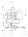
本発明の一実施形態を採用した両軸受リール100は、釣り糸を前方に繰り出し可能である。両軸受リール100は、図1乃至図4に示すように、リール本体2と、スプール3と、ハンドル4と、スプール制動機構20(図3参照)と、操作部材30と、往復移動機構40と、カウンターユニット50と、を備えている。なお、以下の説明において、釣りを行うときに、釣糸が繰り出される方向を前、その反対方向を後という。また、左右とは、両軸受リール100を後方から見たときの左右をいう。また、スプール軸10が延びる方向を軸方向という。
A dual-bearing
リール本体2は、フレーム6と、第1側カバー7と、第2側カバー8と、前カバー9と、を有している。フレーム6は、第1側板6aと、第2側板6bと、複数の連結部6cと、を有している。第1側板6aは、フレーム6の右側に配置されている。第2側板6bは、第1側板6aと軸方向に間隔を隔てて、フレーム6の左側に配置されている。第2側板6bの軸方向外側には、第1ボス部11aを有する支持部材11が第1側板6aに固定されている。複数の連結部6cは、軸方向に延びて第1側板6aと第2側板6bとを連結している。
The
第1側カバー7は、フレーム6の第1側板6aの右側方を覆う。第1側カバー7は、図3に示すように、軸方向外側に突出する第2ボス部7aを有している。第2ボス部7aは、第1側カバー7を軸方向に貫通して形成されている。第2ボス部7aの外周面には雄ねじが形成されている。第2側カバー8は、フレーム6の第2側板6bの左側方を覆う。前カバー9は、フレーム6の前方を覆う。詳細には、前カバー9は、図2及び図4に示すように、往復移動機構40の一部を前方から覆う。
The
スプール3は、第1側板6aと第2側板6bとの間でリール本体2に回転自在に支持されている。また、スプール3は、図3に示すように、スプール3の中央を軸方向に貫通するスプール軸10に支持されている。詳細には、スプール3は、スプール軸10に固定されており、スプール軸10と一体的に回転する。スプール軸10は、リール本体2に配置された1対の軸受12a,12bを介して、リール本体2に回転可能に支持されている。
The
ハンドル4は、リール本体2に回転自在に支持されている。ハンドル4の回転は、図示しないドラグ機構及びスプール軸10回りに装着されたピニオンギア15を介してスプール3に伝達される。
The
なお、両軸受リール100は、図3に示すように、ハンドル4の回転操作に伴うスプール3への回転力の伝達及び遮断を切り換えるクラッチ機構16を有している。クラッチ機構16は、リール本体2の後部に配置されたクラッチ操作部材18の操作によってクラッチオン状態と、クラッチオフ状態とが切り替えられる。クラッチ機構16、及びクラッチ操作部材18の詳細については、従来と同様の構成であるため、詳細な説明を省略する。
As shown in FIG. 3, the dual-
スプール制動機構20は、スプール3の回転を制動するための機構である。本実施形態では、スプール3と一体的に回転するスプール軸10を軸方向に押圧することで、スプール3に作用する制動力が調整される。スプール制動機構20は、調整部材21と、第1摩擦プレート22と、第2摩擦プレート23と、を有している。
The
調整部材21は、リール本体2に軸方向に移動可能に設けられ、軸方向の移動によりスプール3に作用する制動力を調整する。調整部材21は、有底筒状の部材であり、内周面に形成された雌ねじが第2ボス部7aの外周面に形成された雄ねじに螺合する。これにより、調整部材21を回転させると、調整部材21がリール本体2に対して軸方向に移動する。調整部材21は、外周面に雄ねじ部21aを有している。雄ねじ部21aには、後述する規制部材31が係合する。
The adjusting
第1摩擦プレート22は、調整部材21の底部に配置されている。第1摩擦プレート22は、スプール軸10の一端面に接触している。第2摩擦プレート23は、支持部材11の第1ボス部11aの底部に配置されている。第2摩擦プレート23は、スプール軸10の他端面に接触している。第1摩擦プレート22及び第2摩擦プレート23によってスプール軸10の両端が軸方向に押圧されて、スプール軸10の回転が制動される。また、調整部材21の軸方向の移動により、スプール軸10を押圧する押圧力が変化して、スプール3に作用する制動力が調整される。
The
操作部材30は、リール本体2に移動可能に設けられ、移動によりスプール3に作用する制動力を調整操作する。本実施形態では操作部材30は、調整部材21に取り付けられている。操作部材30は、調整部材21の回転方向に調整部材21とともに揺動可能である。操作部材30の揺動に応じて調整部材21が軸方向に移動する。
The operating
操作部材30は、図1乃至図3に示すように、取付部30aと、操作本体部30bと、を有している。取付部30aは、調整部材21に一体回転可能かつ着脱可能に、調整部材21の外周部に取り付けられている。
As shown in FIGS. 1 to 3, the
操作本体部30bは、取付部30aから径方向外側に延びるとともに、径方向外側に延びるにしたがって、リール本体2の内側に向かって傾斜している。また、操作本体部30bは、先端がリール本体2の上面よりもさらに径方向外方に突出可能である。
The operating
例えば、操作部材30の操作本体部30bを図1に示す位置から前方に押し倒すと、調整部材21が第1側カバー7に近づく方向に移動する。この場合は、第1摩擦プレート22及び第2摩擦プレート23がスプール軸10を押圧する押圧力が大きくなり、スプール制動機構20の制動力が大きくなる。反対に、操作部材30の操作本体部30bを図1に示す位置から後方に押し倒すと、調整部材21が第1側カバー7から離れる方向に移動する。この場合は、第1摩擦プレート22及び第2摩擦プレート23がスプール軸10を押圧する押圧力が小さくなり、スプール制動機構20の制動力が小さくなる。
For example, when the
なお、操作部材30は、調整部材21の雄ねじ部21aに係合する筒状の規制部材31により軸方向の移動が規制されている。
Axial movement of the operating
往復移動機構40は、スプール3の回転に同期して釣り糸を軸方向に往復移動させる。往復移動機構40は、図2及び図4に示すように、軸部材41と、案内部材42と、ガイド軸43と、摺動部材44と、を有している。
The
軸部材41は、円柱状であり、第1側板6aと第2側板6bとの間を軸方向に延びて、リール本体2に回転可能に支持されている。軸部材41は、螺旋状溝41aを外周面に有している。案内部材42は、軸部材41の外周側に配置されている。案内部材42及びガイド軸43は、第1側板6aと第2側板6bとの間を軸方向に延びて、摺動部材44の軸方向の移動を案内する。摺動部材44は、スプール3に釣り糸を案内する糸案内部44aと、軸部材41の螺旋状溝41aに係合する係合部44bと、を有している。摺動部材44は、螺旋状溝41aに沿って摺動する。
The
糸案内部44aは、筒状であり、前後方向に延びている。糸案内部44aは、図4に示すように、側面視において、スプール軸10よりも上方に配置されている。
The
往復移動機構40には、図3及び図5に示すように、第2側カバー8の内部に設けられた回転伝達機構45を介して、スプール3の回転が伝達される。回転伝達機構45は、スプール3の回転を往復移動機構40の軸部材41に減速して伝達する。詳細には、回転伝達機構45は、入力ギア46と、第1中間ギア47と、第2中間ギア48と、出力ギア49と、を有している。
Rotation of the
入力ギア46は、スプール軸10の軸回りに配置され、スプール軸10と一体回転する。すなわち、本実施形態では、入力ギア46はスプール3と一体回転する。第1中間ギア47は、図5に示すように、段付ギアであり、大径ギア47aと小径ギア47bと、を有している。大径ギア47aは、スプール3側からの回転入力を受けるギアであり、入力ギア46に噛み合う。小径ギア47bは、大径ギア47aよりも小径のギアであり、大径ギア47aと同芯で一体的に回転する。小径ギア47bは、第2中間ギア48に噛み合い、軸部材41側に回転を出力する。第1中間ギア47及び第2中間ギア48は、第2側板6b及び支持部材11の軸方向間で回転可能に支持されている。出力ギア49は、第2中間ギア48に噛み合い、軸部材41と一体回転可能に連結されている。これにより、入力ギア46から、第1中間ギア47、第2中間ギア48、そして出力ギア49を介してスプール3の回転が往復移動機構40に伝達され、釣り糸が軸方向に往復移動する。
The
ここでは、入力ギア46の回転が第1中間ギア47の大径ギア47aに伝達され、そして大径ギア47aと一体回転する小径ギア47bを介して入力ギア46の回転が出力ギア49に伝達される。これにより、往復移動機構40の軸方向の移動が減速されるため、釣り糸が軸方向に押される力が低下し、例えば、釣り糸を繰り出す時において、釣り糸が糸案内部44aから受ける抵抗が小さくなる。
Here, the rotation of the
カウンターユニット50は、リール本体2の上部に配置されている。カウンターユニット50は、図6に示すように、制御部51と、表示部52と、回転検出部53と、記憶部54と、操作スイッチ55と、を有している。
The
制御部51は、速度算出部56と、水深算出部57と、表示制御部58と、を有している。制御部51には、第2側カバー8の内部に配置された電源59から電力が供給される。電源59は、例えば、円板形のアルカリ電池である。なお、速度算出部56は速度算出手段の一例であり、水深算出部57は水深算出手段の一例であり、表示制御部58は表示制御手段の一例である。
The
制御部51は、マイクロコンピュータを含み、ソフトウェアによって速度算出部56、水深算出部57及び表示制御部58を制御する。速度算出部56は、少なくとも釣り糸の繰り出し速度をスプール3の回転に応じて算出する。本実施形態では、速度算出部56は、釣り糸の繰り出し速度及び巻き取り速度をスプール3の回転に応じて算出する。詳細には、速度算出部56は、回転検出部53からの信号を受けて、スプール3の回転速度を算出する。具体的には、例えば、所定時間毎のスプール3の平均回転数、又はスプール3の所定回転数毎の平均時間を元にスプール3の回転速度を算出する。なお、スプール3の糸巻き径の変化に応じて、スプール3の回転速度を算出してもよい。
The
水深算出部57は、スプール3の回転に応じて水深を算出する。詳細には、スプール3から繰り出された糸長によって仕掛けが配置された水深を算出する。具体的には、記憶部54に予め記憶されたスプール3の回転数と水深との関係から、スプール3が所定位置から何回転したかを元に水深を算出する。
The
表示制御部58は、速度算出部56によって算出されたスプール3の回転速度を、表示部52に表示可能である。詳細には、表示制御部58は、スプール3の回転速度範囲に応じて予め設定された所定の段数に変換して表示部52に表示する。また、表示制御部58は、水深算出部57によって算出された仕掛けの水深を表示部52に表示する。
The
表示部52は、図1に示すように、リール本体2の上部に配置されている。詳細には、表示部52は、カウンターユニット50の上面に配置された液晶ディスプレイである。表示部52には、数値、記号、及び一部のアルファベットが表示可能であり、水深やスプール3の回転速度範囲に応じて予め設定された段数などが状況に応じて表示される。
The
回転検出部53は、スプール3に装着された図示しない磁石を検出可能なリードスイッチ又はホール素子を有している。回転検出部53は、スプール3の回転を検出する。詳細には、回転検出部53は、スプール3の回転数を検出して制御部51に信号を出力する。また、回転検出部53は、スプール3が巻き取り方向及び繰り出し方向のいずれの方向に回転しているかを検出して制御部51に信号を出力する。
The
記憶部54は、例えば、書き換え可能なフラッシュメモリで構成されている。記憶部54には、工場出荷時において、両軸受リール100のスプール3の大きさ、釣り糸の太さ及びスプール3に釣り糸を巻き付けたときのスプール3の回転数と、糸の長さとの関係が少なくとも一つ記憶されている。なお、これらの関係を、公知の学習処理によって記憶部54に記憶させてもよい。
The
操作スイッチ55は、表示部52の右側(第1側カバー7側)に配置されている。操作スイッチ55は、例えば押しボタンで構成されている。この操作スイッチ55を異なる操作方法(例えば、長押し及びダブルクリック)で操作することによって各種の設定操作を行うことができる。
The
上記構成の両軸受リール100では、往復移動機構40がスプール3の回転に同期して、軸方向に往復移動する。これにより、スプール3から釣り糸を繰り出すときに、往復移動機構40の糸案内部44aがスプール3の回転に同期して軸方向に移動する。このため、スプール3から繰り出される釣り糸の位置と、往復移動機構40の糸案内部44aの位置と、の間に、左右方向のずれがない。その結果、スプール3から釣り糸をスムーズに繰り出すことができ、安定した落下速度を得ることできる。さらに、表示部52に表示された仕掛けの水深、若しくは仕掛けの繰り出し速度を確認しながら、スプール3に作用する制動力を操作部材30で調整することで、状況に適した仕掛けの落下速度を容易に得ることができる。
In the dual-
<他の実施形態>
以上、本発明の一実施形態について説明したが、本発明は上記実施形態に限定されるものではなく、発明の要旨を逸脱しない範囲で種々の変更が可能である。特に、本明細書に書かれた複数の実施形態は必要に応じて任意に組合せ可能である。
<Other embodiments>
Although one embodiment of the present invention has been described above, the present invention is not limited to the above-described embodiment, and various modifications are possible without departing from the gist of the invention. In particular, multiple embodiments described herein can be arbitrarily combined as required.
(a) 上記実施形態では、スプール制動機構20をスプール3と一体的に回転するスプール軸10を軸方向に押圧するように構成していたが、スプール軸10やスプール3に径方向から接触して摩擦抵抗を加えるものであってもよい。また、図7に示すように、スプール軸10に一体回転可能に係合した係合部材61に制動力を作用させてもよい。詳細には、両軸受リール200のスプール制動機構120は、スプール軸10の先端を覆う係合部材61が第2摩擦プレート23に接触して、スプール軸10の回転が制動される。この場合は、係合部材61により、第2摩擦プレート23に接触する面積が大きくなり、制動力も大きくなる。このため、例えば、スプール3の径が大きいリールにおいて、操作部材30をわずかに操作しただけで、制動力の調整が可能になる。
(a) In the above embodiment, the
(b) 上記実施形態では、操作部材30を調整部材21に取付けていたが、調整部材21と操作部材30を一体で形成してもよい。また、レバー形式でなく、ダイヤル式やスライドレバー式など、リールを把持する手の指で操作できるものであれば様式は問わない。
(b) In the above embodiment, the operating
(c) 上記実施形態では、スプール3に直接制動力を作用させていたが、スプール3から往復移動機構40に回転を伝達する回転伝達機構45を構成するギアに制動力を付与してもよい。
(c) In the above embodiment, the braking force is applied directly to the
(d) スプール制動機構20はさらに一方向クラッチを備えて、スプール3の釣り糸繰出し方向のみに制動力を作用するように構成してもよい。
(d) The
上記実施形態では、ハンドル4の操作で巻き取り可能な両軸受リール100を例にして本発明を説明したが、モータ駆動で巻き取り可能な電動リールに本発明を適用してもよい。
In the above-described embodiment, the present invention has been described by taking as an example the dual-
2 リール本体
3 スプール
9 前カバー
10 スプール軸
21 調整部材
22 第1摩擦プレート
23 第2摩擦プレート
30 操作部材
30a 取付部
30b 操作本体部
40 往復移動機構
41 軸部材
41a 螺旋状溝
44 摺動部材
44a 糸案内部
45 回転伝達機構
47a 大径ギア
47b 小径ギア
52 表示部
56 速度算出部(速度算出手段の一例)
57 水深算出部(水深算出手段の一例)
58 表示制御部(表示制御部の一例)
100 両軸受リール
2
57 Water depth calculation unit (an example of water depth calculation means)
58 Display control unit (an example of a display control unit)
100 double bearing reel
Claims (6)
リール本体と、
前記リール本体に回転自在に支持されたスプールと、
前記スプールを支持し、前記スプールと一体的に回転するスプール軸と、
前記スプール軸の一端面に接触する第1摩擦プレートと、
前記スプール軸の他端面に接触する第2摩擦プレートと、
前記スプール軸の軸方向に移動可能に設けられ、軸方向の移動により前記第1及プレート及び第2摩擦プレートによって前記スプール軸を押圧する押圧力を変化させ、前記スプールに作用する制動力を調整し、前記スプールの回転速度を調整する調整部材と、
前記調整部材に取り付けられて前記リール本体に移動可能に設けられ、前記調整部材の回転方向に前記調整部材とともに揺動可能であり、揺動に応じて前記調整部材を軸方向に移動させて前記第1及び第2摩擦プレートの前記スプール軸への押圧力を調整することで、前記スプールに作用する制動力を調整し、前記スプールの回転速度を調整操作する操作部材と、
前記操作部材によって調整操作された前記スプールの回転に同期して前記釣り糸を軸方向に往復移動させる往復移動機構と、
前記リール本体の上面に設けられた表示部と、
前記操作部材によって調整操作された前記スプールの回転に応じて仕掛けの水深を算出する水深算出手段と、
少なくとも前記釣り糸の繰り出し速度を前記操作部材によって調整操作された前記スプールの回転に応じて算出する速度算出手段と、
前記水深算出手段により前記操作部材によって調整操作された前記スプールの回転に応じて算出された仕掛けの水深を前記表示部に表示させ、前記速度算出手段により前記操作部材によって調整操作された前記スプールの回転に応じて算出された速度を前記表示部に表示可能な表示制御手段と、
を備え、
前記操作部材は、
前記調整部材に一体回転可能かつ着脱可能な取付部と、
前記取付部から径方向外側に延びるとともに、径方向外側に延びるにしたがって前記リール本体の内側に向かって傾斜し、前記リール本体と径方向に重なる操作本体部と、
を有し、
前記操作部材の操作本体部の先端は、前記表示部よりさらに径方向外方に突出可能である、両軸受リール。
A dual-bearing reel capable of winding and unwinding fishing line,
a reel body;
a spool rotatably supported by the reel body;
a spool shaft that supports the spool and rotates integrally with the spool ;
a first friction plate in contact with one end surface of the spool shaft;
a second friction plate in contact with the other end surface of the spool shaft;
It is provided movably in the axial direction of the spool shaft, and by moving in the axial direction, the pressing force that presses the spool shaft by the first plate and the second friction plate is changed, and the braking force acting on the spool is adjusted. and an adjusting member for adjusting the rotation speed of the spool;
The adjusting member is attached to the adjusting member and is movably provided on the reel body, and is capable of swinging together with the adjusting member in the rotational direction of the adjusting member. an operation member that adjusts the braking force acting on the spool by adjusting the pressing force of the first and second friction plates against the spool shaft , and adjusts the rotational speed of the spool ;
a reciprocating mechanism for axially reciprocating the fishing line in synchronization with the rotation of the spool adjusted by the operating member ;
a display section provided on the upper surface of the reel body;
water depth calculation means for calculating the water depth of the tackle according to the rotation of the spool adjusted by the operation member ;
speed calculation means for calculating at least the speed at which the fishing line is let out according to the rotation of the spool adjusted by the operation member ;
The water depth of the tackle calculated by the water depth calculation means according to the rotation of the spool adjusted by the operation member is displayed on the display unit, and the speed calculation means causes the speed calculation means to display the water depth of the spool adjusted by the operation member. display control means capable of displaying the speed calculated according to the rotation on the display;
with
The operating member is
a mounting portion that is integrally rotatable with and detachable from the adjustment member;
an operation main body portion extending radially outward from the mounting portion, sloping toward the inner side of the reel body as it extends radially outward, and overlapping the reel body in the radial direction;
has
The double-bearing reel , wherein the tip of the operation main body of the operation member can protrude further radially outward than the display portion .
請求項1に記載の両軸受リール。A dual-bearing reel according to claim 1.
前記糸案内部は、側面視において、前記スプール軸よりも上方に配置されている、
請求項1又は2に記載の両軸受リール。
The reciprocating mechanism has a line guide section that guides the fishing line,
The thread guide portion is arranged above the spool shaft in a side view,
The dual-bearing reel according to claim 1 or 2 .
前記リール本体に回転可能に支持されるとともに、外周面に螺旋状溝を有し、前記スプール軸の軸方向に延びる軸部材と、
前記螺旋状溝に沿って摺動する摺動部材と、
を有し、
前記スプール軸の軸回りに配置された入力ギアを含み、前記スプールの回転を前記往復移動機構の前記軸部材に伝達する回転伝達機構をさらに備えた、
請求項1から3のいずれか1項に記載の両軸受リール。
The reciprocating mechanism includes:
a shaft member rotatably supported by the reel body, having a spiral groove on an outer peripheral surface thereof, and extending in the axial direction of the spool shaft;
a sliding member that slides along the spiral groove;
has
A rotation transmission mechanism including an input gear arranged around the spool shaft and transmitting rotation of the spool to the shaft member of the reciprocating mechanism,
A dual-bearing reel according to any one of claims 1 to 3 .
請求項4に記載の両軸受リール。
The rotation transmission mechanism decelerates and transmits the rotation of the spool to the shaft member,
A dual-bearing reel according to claim 4 .
請求項5に記載の両軸受リール。 The rotation transmission mechanism has a large-diameter gear that receives rotational input from the spool side, and a small-diameter gear that rotates concentrically and integrally with the large-diameter gear and outputs rotation to the shaft member side.
A dual-bearing reel according to claim 5 .
Priority Applications (6)
| Application Number | Priority Date | Filing Date | Title |
|---|---|---|---|
| JP2017224466A JP7262167B2 (en) | 2017-11-22 | 2017-11-22 | Double bearing reel |
| KR1020180109809A KR102638044B1 (en) | 2017-11-22 | 2018-09-13 | Dual-bearing reel |
| US16/160,016 US10721923B2 (en) | 2017-11-22 | 2018-10-15 | Dual-bearing reel |
| MYPI2018704099A MY195926A (en) | 2017-11-22 | 2018-11-02 | Dual-Bearing Reel |
| CN201811353404.3A CN110012881B (en) | 2017-11-22 | 2018-11-14 | Dual-bearing fishing reel |
| TW107141362A TWI794338B (en) | 2017-11-22 | 2018-11-21 | Dual-bearing reel |
Applications Claiming Priority (1)
| Application Number | Priority Date | Filing Date | Title |
|---|---|---|---|
| JP2017224466A JP7262167B2 (en) | 2017-11-22 | 2017-11-22 | Double bearing reel |
Publications (3)
| Publication Number | Publication Date |
|---|---|
| JP2019092429A JP2019092429A (en) | 2019-06-20 |
| JP2019092429A5 JP2019092429A5 (en) | 2020-12-03 |
| JP7262167B2 true JP7262167B2 (en) | 2023-04-21 |
Family
ID=66533816
Family Applications (1)
| Application Number | Title | Priority Date | Filing Date |
|---|---|---|---|
| JP2017224466A Active JP7262167B2 (en) | 2017-11-22 | 2017-11-22 | Double bearing reel |
Country Status (6)
| Country | Link |
|---|---|
| US (1) | US10721923B2 (en) |
| JP (1) | JP7262167B2 (en) |
| KR (1) | KR102638044B1 (en) |
| CN (1) | CN110012881B (en) |
| MY (1) | MY195926A (en) |
| TW (1) | TWI794338B (en) |
Cited By (2)
| Publication number | Priority date | Publication date | Assignee | Title |
|---|---|---|---|---|
| US11830028B2 (en) | 2013-07-12 | 2023-11-28 | The Nielsen Company (Us), Llc | Methods and apparatus to collect distributed user information for media impressions |
| US11854049B2 (en) | 2013-12-23 | 2023-12-26 | The Nielsen Company (Us), Llc | Methods and apparatus to measure media using media object characteristics |
Citations (3)
| Publication number | Priority date | Publication date | Assignee | Title |
|---|---|---|---|---|
| JP2000262194A (en) | 1999-03-19 | 2000-09-26 | Shimano Inc | Braking device for reel supported on both ends with bearings |
| JP2002306033A (en) | 2001-04-16 | 2002-10-22 | Shimano Inc | Double bearing reel |
| JP2016220547A (en) | 2015-05-27 | 2016-12-28 | 株式会社シマノ | Double-bearing reel |
Family Cites Families (26)
| Publication number | Priority date | Publication date | Assignee | Title |
|---|---|---|---|---|
| US5207396A (en) * | 1990-12-28 | 1993-05-04 | Shimano, Inc. | Fishing reel |
| JPH09275861A (en) * | 1996-04-19 | 1997-10-28 | Shimano Inc | Brake device for both-bearing reel |
| JP3534574B2 (en) * | 1997-06-20 | 2004-06-07 | 株式会社シマノ | Double bearing reel |
| JP2000270734A (en) * | 1999-03-24 | 2000-10-03 | Shimano Inc | Water depth display system for fishing reel |
| JP3793134B2 (en) * | 2002-09-30 | 2006-07-05 | 株式会社シマノ | Fishing information display device and fishing information display system |
| KR101114296B1 (en) * | 2003-12-04 | 2012-03-05 | 가부시키가이샤 시마노 | Fishing data display device |
| US7165737B2 (en) * | 2005-01-18 | 2007-01-23 | Shimano Inc. | Spool braking device for dual-bearing reel |
| JP4934420B2 (en) * | 2006-12-19 | 2012-05-16 | 株式会社シマノ | Spinning reel spool |
| JP4863891B2 (en) * | 2007-01-23 | 2012-01-25 | 株式会社シマノ | Double bearing reel |
| JP2011019428A (en) * | 2009-07-14 | 2011-02-03 | Shimano Inc | Dual-bearing reel lever drag mechanism |
| JP5616087B2 (en) * | 2010-03-23 | 2014-10-29 | 株式会社シマノ | Single bearing reel |
| JP5654270B2 (en) * | 2010-06-25 | 2015-01-14 | 株式会社シマノ | Fishing reel |
| JP5798808B2 (en) * | 2011-06-17 | 2015-10-21 | 株式会社シマノ | Electric reel |
| JP5755044B2 (en) * | 2011-06-20 | 2015-07-29 | 株式会社シマノ | Double-bearing reel drag mechanism |
| JP6085447B2 (en) * | 2012-10-19 | 2017-02-22 | 株式会社シマノ | Spool braking device for double-bearing reel |
| CN103004714B (en) * | 2012-11-30 | 2015-07-08 | 宁波海宝渔具有限公司 | Spinning wheel type fishing line reel with novel reciprocating mechanism for fishing |
| JP6368525B2 (en) * | 2014-04-16 | 2018-08-01 | 株式会社シマノ | Clutch operating member for dual-bearing reel |
| JP6488098B2 (en) * | 2014-10-10 | 2019-03-20 | 株式会社シマノ | Double bearing reel |
| CN204634802U (en) * | 2015-05-26 | 2015-09-16 | 毛水江 | A kind of fishing line reel |
| JP6560904B2 (en) * | 2015-05-27 | 2019-08-14 | 株式会社シマノ | Double bearing reel |
| JP6653582B2 (en) * | 2016-01-19 | 2020-02-26 | 株式会社シマノ | Double bearing reel |
| JP6572139B2 (en) * | 2016-01-22 | 2019-09-04 | 株式会社シマノ | Fishing reel |
| JP6649801B2 (en) * | 2016-02-26 | 2020-02-19 | 株式会社シマノ | Double bearing reel |
| JP6829654B2 (en) * | 2017-06-05 | 2021-02-10 | 株式会社シマノ | Fishing reel |
| US10602730B2 (en) * | 2017-06-23 | 2020-03-31 | Shimano Inc. | Dual-bearing reel |
| JP6941560B2 (en) * | 2017-12-28 | 2021-09-29 | 株式会社シマノ | Bearing accommodation structure and double bearing reel |
-
2017
- 2017-11-22 JP JP2017224466A patent/JP7262167B2/en active Active
-
2018
- 2018-09-13 KR KR1020180109809A patent/KR102638044B1/en active IP Right Grant
- 2018-10-15 US US16/160,016 patent/US10721923B2/en active Active
- 2018-11-02 MY MYPI2018704099A patent/MY195926A/en unknown
- 2018-11-14 CN CN201811353404.3A patent/CN110012881B/en active Active
- 2018-11-21 TW TW107141362A patent/TWI794338B/en active
Patent Citations (3)
| Publication number | Priority date | Publication date | Assignee | Title |
|---|---|---|---|---|
| JP2000262194A (en) | 1999-03-19 | 2000-09-26 | Shimano Inc | Braking device for reel supported on both ends with bearings |
| JP2002306033A (en) | 2001-04-16 | 2002-10-22 | Shimano Inc | Double bearing reel |
| JP2016220547A (en) | 2015-05-27 | 2016-12-28 | 株式会社シマノ | Double-bearing reel |
Cited By (2)
| Publication number | Priority date | Publication date | Assignee | Title |
|---|---|---|---|---|
| US11830028B2 (en) | 2013-07-12 | 2023-11-28 | The Nielsen Company (Us), Llc | Methods and apparatus to collect distributed user information for media impressions |
| US11854049B2 (en) | 2013-12-23 | 2023-12-26 | The Nielsen Company (Us), Llc | Methods and apparatus to measure media using media object characteristics |
Also Published As
| Publication number | Publication date |
|---|---|
| TWI794338B (en) | 2023-03-01 |
| MY195926A (en) | 2023-02-27 |
| TW201924525A (en) | 2019-07-01 |
| JP2019092429A (en) | 2019-06-20 |
| US10721923B2 (en) | 2020-07-28 |
| KR20190059199A (en) | 2019-05-30 |
| CN110012881A (en) | 2019-07-16 |
| US20190150418A1 (en) | 2019-05-23 |
| CN110012881B (en) | 2021-12-03 |
| KR102638044B1 (en) | 2024-02-19 |
Similar Documents
| Publication | Publication Date | Title |
|---|---|---|
| JP5755083B2 (en) | Electric reel control device | |
| JP5764014B2 (en) | Double bearing reel tension display device | |
| JP7262167B2 (en) | Double bearing reel | |
| CN105265401B (en) | Dual-bearing reel and clutch mechanism for dual-bearing reel | |
| JP2013048594A5 (en) | ||
| JP2014100078A5 (en) | ||
| JP6133677B2 (en) | Electric reel | |
| JP2014217278A5 (en) | ||
| CN102405890B (en) | Electric fishing reel | |
| JP2019092429A5 (en) | ||
| JP6342218B2 (en) | Electric reel motor control device | |
| JP2018050587A5 (en) | ||
| JP5698066B2 (en) | Fishing electric reel | |
| JP6284307B2 (en) | Electric reel motor control device | |
| US838915A (en) | Fishing-reel. | |
| JP2014233260A (en) | Spool brake device of double-bearing reel | |
| JP2015002689A5 (en) | ||
| JP6143657B2 (en) | Fishing reel | |
| JP2009148220A (en) | Electric reel for fishing | |
| JP7100990B2 (en) | Electric reel | |
| TWI821471B (en) | Reel drive control device for electric reel for fishing tackle and electric reel for fishing tackle equipped with the same, reel drive control method and reel drive control program | |
| JP5748438B2 (en) | Electric reel | |
| US5297758A (en) | Fishing reel with click sound generator | |
| JP4366146B2 (en) | Electric reel | |
| JP2002253091A (en) | Clutch mechanism for fishing double-bearing reel |
Legal Events
| Date | Code | Title | Description |
|---|---|---|---|
| A521 | Request for written amendment filed |
Free format text: JAPANESE INTERMEDIATE CODE: A523 Effective date: 20201026 |
|
| A621 | Written request for application examination |
Free format text: JAPANESE INTERMEDIATE CODE: A621 Effective date: 20201026 |
|
| A977 | Report on retrieval |
Free format text: JAPANESE INTERMEDIATE CODE: A971007 Effective date: 20210917 |
|
| A131 | Notification of reasons for refusal |
Free format text: JAPANESE INTERMEDIATE CODE: A131 Effective date: 20211005 |
|
| A521 | Request for written amendment filed |
Free format text: JAPANESE INTERMEDIATE CODE: A523 Effective date: 20211129 |
|
| A02 | Decision of refusal |
Free format text: JAPANESE INTERMEDIATE CODE: A02 Effective date: 20220329 |
|
| A521 | Request for written amendment filed |
Free format text: JAPANESE INTERMEDIATE CODE: A523 Effective date: 20220628 |
|
| C60 | Trial request (containing other claim documents, opposition documents) |
Free format text: JAPANESE INTERMEDIATE CODE: C60 Effective date: 20220628 |
|
| A911 | Transfer to examiner for re-examination before appeal (zenchi) |
Free format text: JAPANESE INTERMEDIATE CODE: A911 Effective date: 20220705 |
|
| C21 | Notice of transfer of a case for reconsideration by examiners before appeal proceedings |
Free format text: JAPANESE INTERMEDIATE CODE: C21 Effective date: 20220712 |
|
| A912 | Re-examination (zenchi) completed and case transferred to appeal board |
Free format text: JAPANESE INTERMEDIATE CODE: A912 Effective date: 20220805 |
|
| C211 | Notice of termination of reconsideration by examiners before appeal proceedings |
Free format text: JAPANESE INTERMEDIATE CODE: C211 Effective date: 20220809 |
|
| C22 | Notice of designation (change) of administrative judge |
Free format text: JAPANESE INTERMEDIATE CODE: C22 Effective date: 20221213 |
|
| C22 | Notice of designation (change) of administrative judge |
Free format text: JAPANESE INTERMEDIATE CODE: C22 Effective date: 20230214 |
|
| C23 | Notice of termination of proceedings |
Free format text: JAPANESE INTERMEDIATE CODE: C23 Effective date: 20230228 |
|
| C03 | Trial/appeal decision taken |
Free format text: JAPANESE INTERMEDIATE CODE: C03 Effective date: 20230328 |
|
| C30A | Notification sent |
Free format text: JAPANESE INTERMEDIATE CODE: C3012 Effective date: 20230328 |
|
| A61 | First payment of annual fees (during grant procedure) |
Free format text: JAPANESE INTERMEDIATE CODE: A61 Effective date: 20230411 |
|
| R150 | Certificate of patent or registration of utility model |
Ref document number: 7262167 Country of ref document: JP Free format text: JAPANESE INTERMEDIATE CODE: R150 |