JP6653582B2 - Double bearing reel - Google Patents
Double bearing reel Download PDFInfo
- Publication number
- JP6653582B2 JP6653582B2 JP2016008320A JP2016008320A JP6653582B2 JP 6653582 B2 JP6653582 B2 JP 6653582B2 JP 2016008320 A JP2016008320 A JP 2016008320A JP 2016008320 A JP2016008320 A JP 2016008320A JP 6653582 B2 JP6653582 B2 JP 6653582B2
- Authority
- JP
- Japan
- Prior art keywords
- spool
- moving member
- dual
- axis
- cam
- Prior art date
- Legal status (The legal status is an assumption and is not a legal conclusion. Google has not performed a legal analysis and makes no representation as to the accuracy of the status listed.)
- Active
Links
- 230000007246 mechanism Effects 0.000 claims description 126
- 230000009977 dual effect Effects 0.000 claims description 52
- 238000001514 detection method Methods 0.000 claims description 16
- 238000004804 winding Methods 0.000 claims description 12
- 230000005540 biological transmission Effects 0.000 description 5
- 230000004048 modification Effects 0.000 description 4
- 238000012986 modification Methods 0.000 description 4
- 230000002093 peripheral effect Effects 0.000 description 4
- 239000000758 substrate Substances 0.000 description 3
- 239000004698 Polyethylene Substances 0.000 description 2
- 238000005266 casting Methods 0.000 description 2
- 230000008859 change Effects 0.000 description 2
- 238000010586 diagram Methods 0.000 description 2
- 230000005669 field effect Effects 0.000 description 2
- 239000004677 Nylon Substances 0.000 description 1
- 239000002033 PVDF binder Substances 0.000 description 1
- 239000003990 capacitor Substances 0.000 description 1
- 239000003989 dielectric material Substances 0.000 description 1
- 239000000835 fiber Substances 0.000 description 1
- NBVXSUQYWXRMNV-UHFFFAOYSA-N fluoromethane Chemical compound FC NBVXSUQYWXRMNV-UHFFFAOYSA-N 0.000 description 1
- 230000004907 flux Effects 0.000 description 1
- 230000006870 function Effects 0.000 description 1
- 238000009499 grossing Methods 0.000 description 1
- 239000004973 liquid crystal related substance Substances 0.000 description 1
- 229920001778 nylon Polymers 0.000 description 1
- -1 polyethylene Polymers 0.000 description 1
- 229920000573 polyethylene Polymers 0.000 description 1
- 229920002981 polyvinylidene fluoride Polymers 0.000 description 1
- 229920003002 synthetic resin Polymers 0.000 description 1
- 239000000057 synthetic resin Substances 0.000 description 1
- XLYOFNOQVPJJNP-UHFFFAOYSA-N water Substances O XLYOFNOQVPJJNP-UHFFFAOYSA-N 0.000 description 1
Images


Classifications
-
- A—HUMAN NECESSITIES
- A01—AGRICULTURE; FORESTRY; ANIMAL HUSBANDRY; HUNTING; TRAPPING; FISHING
- A01K—ANIMAL HUSBANDRY; CARE OF BIRDS, FISHES, INSECTS; FISHING; REARING OR BREEDING ANIMALS, NOT OTHERWISE PROVIDED FOR; NEW BREEDS OF ANIMALS
- A01K89/00—Reels
- A01K89/015—Reels with a rotary drum, i.e. with a rotating spool
- A01K89/01931—Spool or spool shaft details
-
- A—HUMAN NECESSITIES
- A01—AGRICULTURE; FORESTRY; ANIMAL HUSBANDRY; HUNTING; TRAPPING; FISHING
- A01K—ANIMAL HUSBANDRY; CARE OF BIRDS, FISHES, INSECTS; FISHING; REARING OR BREEDING ANIMALS, NOT OTHERWISE PROVIDED FOR; NEW BREEDS OF ANIMALS
- A01K89/00—Reels
- A01K89/015—Reels with a rotary drum, i.e. with a rotating spool
- A01K89/017—Reels with a rotary drum, i.e. with a rotating spool motor-driven
- A01K89/0171—Spring motors
- A01K89/0173—Spring motors with independent manual drive
-
- A—HUMAN NECESSITIES
- A01—AGRICULTURE; FORESTRY; ANIMAL HUSBANDRY; HUNTING; TRAPPING; FISHING
- A01K—ANIMAL HUSBANDRY; CARE OF BIRDS, FISHES, INSECTS; FISHING; REARING OR BREEDING ANIMALS, NOT OTHERWISE PROVIDED FOR; NEW BREEDS OF ANIMALS
- A01K89/00—Reels
- A01K89/015—Reels with a rotary drum, i.e. with a rotating spool
- A01K89/017—Reels with a rotary drum, i.e. with a rotating spool motor-driven
-
- A—HUMAN NECESSITIES
- A01—AGRICULTURE; FORESTRY; ANIMAL HUSBANDRY; HUNTING; TRAPPING; FISHING
- A01K—ANIMAL HUSBANDRY; CARE OF BIRDS, FISHES, INSECTS; FISHING; REARING OR BREEDING ANIMALS, NOT OTHERWISE PROVIDED FOR; NEW BREEDS OF ANIMALS
- A01K89/00—Reels
- A01K89/015—Reels with a rotary drum, i.e. with a rotating spool
- A01K89/0183—Drive mechanism details
Description
本発明は、釣り用リール、特に、釣り糸を前方に繰り出す両軸受リールに関する。 The present invention relates to a fishing reel, and more particularly to a dual-bearing reel that feeds fishing line forward.
両軸受リールには、糸巻き用のスプールがリール本体に回転自在に設けられる。両軸受リールには、スプールに対して動作するスプール動作機構を有するものがある(例えば、特許文献1参照)。特許文献1には、スプール動作機構として、キャスティング時にスプールの糸繰り出し方向の回転を、電気的に制御可能に制動するスプール制動部を有する両軸受リールが開示されている。特許文献1の両軸受リールには回路基板が設けられる。回路基板には、制御用のマイクロコンピュータおよび操作部材の移動位置を検出する検出部が設けられる。
A spool for thread winding is rotatably provided on the reel body of the dual-bearing reel. Some dual-bearing reels have a spool operation mechanism that operates on a spool (see, for example, Patent Document 1).
スプール制動部等のスプール動作機構の大きさは、リールの大きさによって変化する場合がある。従来の両軸受リールでは、リールの大きさに応じて操作部材の位置及び大きさが変化し、回路基板の検出部の位置が変化する。このため、リールの大きさに応じた複数の回路基板を使用する必要がある。 The size of the spool operation mechanism such as the spool braking unit may change depending on the size of the reel. In the conventional dual-bearing reel, the position and size of the operation member change according to the size of the reel, and the position of the detection unit on the circuit board changes. Therefore, it is necessary to use a plurality of circuit boards corresponding to the size of the reel.
本発明の課題は、電気的に制御可能なスプール動作機構を有する両軸受リールにおいて、両軸受リールの大きさにかかわらず一種類の回路基板を使用できるようにすることにある。 An object of the present invention is to make it possible to use one type of circuit board in a dual-bearing reel having an electrically controllable spool operation mechanism regardless of the size of the dual-bearing reel.
本発明に係る両軸受リールは、釣り糸を前方に繰り出す。両軸受リールは、リール本体と、糸巻き用のスプールと、回路基板と、少なくとも一つの移動部材と、スプール動作機構と、少なくとも一つの操作部材と、連動機構と、スプール制御部と、を備える。糸巻き用のスプールは、リール本体に回転自在に設けられる。回路基板は、第1軸回りの回動位置を検出可能な少なくとも一つの回転検出部を有する。少なくとも一つの移動部材は、回転検出部によって回動位置が検出される。スプール動作機構は、スプールに対して電気的に制御可能に動作し、移動部材によって動作状態を調整可能である。少なくとも一つの操作部材は、リール本体に移動可能に設けられ、スプール動作機構の動作状態を調整操作するように構成される。連動機構は、操作部材の移動に応じて移動部材を回転させる。スプール制御部は、移動部材の回動位置に応じてスプール動作機構を制御する。 In the dual bearing reel according to the present invention, the fishing line is fed forward. The dual-bearing reel includes a reel body, a spool for thread winding, a circuit board, at least one moving member, a spool operating mechanism, at least one operating member, an interlocking mechanism, and a spool control unit. The spool for thread winding is rotatably provided on the reel body. The circuit board has at least one rotation detection unit that can detect a rotation position about the first axis. The rotation position of at least one moving member is detected by the rotation detection unit. The spool operation mechanism operates so as to be electrically controllable with respect to the spool, and the operation state can be adjusted by the moving member. The at least one operation member is movably provided on the reel body, and is configured to adjust the operation state of the spool operation mechanism. The interlocking mechanism rotates the moving member according to the movement of the operation member. The spool control unit controls the spool operation mechanism according to the turning position of the moving member.
この両軸受リールでは、操作部材を操作して移動させると、連動機構によって移動部材は操作部材と連動して第1軸回りに回転する。移動部材が回転すると回転検出部が移動部材の回動位置を検出し、スプール制御部がスプール動作機構を移動部材の回動位置に応じて制御する。ここでは、回転検出部が検出する移動部材を、操作部材に直接連結するのではなく、連動機構を介して操作部材に連結したので、移動部材、回転検出部及び回路基板を、異なる大きさの両軸受リールにおいて共通化できる。このため、両軸受リールの大きさにかかわらず一種類の回路基板を使用できるようになる。 In this dual-bearing reel, when the operating member is operated and moved, the moving member rotates around the first axis in conjunction with the operating member by the interlocking mechanism. When the moving member rotates, the rotation detecting unit detects the turning position of the moving member, and the spool control unit controls the spool operation mechanism according to the turning position of the moving member. Here, the moving member detected by the rotation detection unit is not directly connected to the operation member, but is connected to the operation member via an interlocking mechanism, so that the movement member, the rotation detection unit, and the circuit board are of different sizes. It can be common to both bearing reels. Therefore, one type of circuit board can be used regardless of the size of the dual-bearing reel.
操作部材は、リール本体に第1軸と平行に設けられた第2軸回りに回動可能に設けられてもよい。この構成によれば、操作部材も回動するので、連動機構の構成を簡素化できる。 The operating member may be provided rotatably around a second axis provided on the reel body in parallel with the first axis. According to this configuration, since the operation member also rotates, the configuration of the interlocking mechanism can be simplified.
連動機構は、操作部材の移動に連動して移動部材を回動させるカム機構を有してもよい。この構成によれば、カムとカムフォロアとを有するカム機構によって連動機構を構成できるので、連動機構の構成をさらに簡素化できる。 Interlocking mechanism may include a cam mechanism for rotating the moving member in conjunction with the move of the operation member. According to this configuration, it constitutes the interlocking mechanism by a cam mechanism having a cam and cam follower A, can further simplify the configuration of the interlocking mechanism.
移動部材は、操作部材と径方向に重複して配置されてもよい。この構成によれば、移動部材と操作部材とを径方向に重複して配置するので、両軸受リールの径方向の大きさをコンパクトに構成できる。 The moving member may be arranged to overlap the operation member in the radial direction. According to this configuration, since the moving member and the operating member are arranged overlapping in the radial direction, the radial size of the dual-bearing reel can be made compact.
スプール動作機構は、回路基板に装着されるコイルと、スプールに一体回転可能に設けられた磁石と、を有し、スプールを制動するスプール制動部であってもよい。回転検出部は、ケースと、ケースに第1軸回りに回動自在に支持された軸部材と、ケース内に設けられ、軸部材の回動位置を検出可能なセンサ部とを有してもよい。移動部材は、軸部材に第1軸回りに一体的に回動可能に設けられてもよい。この構成によれば、コイルに流れる電流を制御することによって、スプールを制動するスプール制動部において、両軸受リールの大きさにかかわらず一種類の回路基板を使用できるようになる。 The spool operating mechanism may be a spool braking unit that has a coil mounted on the circuit board and a magnet that is rotatably provided on the spool and that brakes the spool. The rotation detection unit may include a case, a shaft member rotatably supported on the case around the first axis, and a sensor unit provided in the case and capable of detecting a rotation position of the shaft member. Good. The moving member may be provided on the shaft member so as to be integrally rotatable around the first shaft . According to this configuration, by controlling the current flowing through the coil, the spool brake unit for braking the spool, so one type of the circuit board regardless of the size of the dual-bearing reel can be used.
スプール動作機構は、リール本体に固定されたモータを有し、モータによってスプールを回転駆動するスプール駆動部であってもよい。操作部材は、リール本体に第2軸回りに回動可能に設けられてもよい。この構成によれば、モータによってスプールを回転駆動するスプール駆動部において、両軸受リールの大きさにかかわらず一種類の回路基板を使用できるようになる。 The spool operation mechanism may include a motor fixed to the reel body, and may be a spool driving unit that rotates the spool by the motor. The operation member may be provided on the reel body so as to be rotatable around the second axis. According to this configuration, one kind of circuit board can be used regardless of the size of the dual-bearing reel in the spool drive unit that rotates the spool by the motor.
カム機構は、移動部材及び操作部材の一方に設けられるカムと、移動部材及び操作部材の他方に設けられ、カムに係合するカムフォロアと、を有してもよい。この構成によれば、カム機構によって、連動機構を簡素な構成によって実現できる。 The cam mechanism may include a cam provided on one of the moving member and the operating member, and a cam follower provided on the other of the moving member and the operating member and engaging with the cam. According to this configuration, the interlocking mechanism can be realized with a simple configuration by the cam mechanism.
カムは、操作部材に径方向に沿って形成されたカム溝を有してもよい。カムフォロアは、移動部材に第1軸と離反した位置に第1軸と平行に配置され、カム溝の壁面に接触可能な突起部を有してもよい。この構成によれば、突起部をカム溝に係合させることによって、操作部材の第2軸回りの回転を、移動部材の第1軸回りの回転に容易に伝達できる。 The cam may have a cam groove formed in the operation member along the radial direction. The cam follower may be disposed on the moving member at a position away from the first axis and in parallel with the first axis, and may have a protrusion that can contact a wall surface of the cam groove. According to this configuration, the rotation of the operation member about the second axis can be easily transmitted to the rotation of the moving member about the first axis by engaging the projection with the cam groove.
両軸受リールは、操作部材の移動位置を複数段階に位置決め可能な位置決め機構をさらに備えてもよい。この構成によれば、操作部材が位置決めされるので、スプール動作機構の動作状態を再現しやすくなる。 The dual bearing reel may further include a positioning mechanism capable of positioning the moving position of the operation member in a plurality of steps. According to this configuration, since the operation member is positioned, the operation state of the spool operation mechanism can be easily reproduced.
本発明によれば、電気的に制御可能なスプール動作機構を有する両軸受リールにおいて、両軸受リールの大きさにかかわらず一種類の回路基板を使用できるようになる。 According to the present invention, in a dual-bearing reel having an electrically controllable spool operation mechanism, one type of circuit board can be used regardless of the size of the dual-bearing reel.
<第1実施形態>
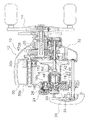
図1および図2において、本発明の第1実施形態に係る両軸受リール10は、釣り糸を前方に繰り出す。両軸受リール10は、リール本体12と、ハンドル14と、糸巻き用のスプール16と、回転検出部19を有する回路基板18と、少なくとも一つの移動部材20(図2参照)と、スプール動作機構としてのスプール制動部22と、少なくとも一つの操作部材24と、連動機構26と、スプール制御部28(図3参照)と、位置決め機構29、とを備える。
<First embodiment>
1 and 2, the dual-bearing
図2に示すように、リール本体12は、間隔をあけて対向して配置された第1側板30a及び第2側板30bを有するフレーム30と、第1側カバー32と、第2側カバー34と、軸支持部36と、を有する。第1側カバー32は、ハンドル14側の第1側板30aの外側面を覆う。第2側カバー34は、第2側板30bの外側を覆う。第2側カバー34は開閉可能である。軸支持部36は、スプール16を回転自在に支持する。軸支持部36は、扁平有底円筒状に形成され、第2側板30bに着脱可能にネジ止め固定される。軸支持部36は、後述するスプール軸46の一端を支持する軸受47aを収容する筒状の軸受収容部36aと、連動機構26を装着する連動機構装着部36bと、を有する。連動機構装着部36bは、図5に示すように、連動機構26を装着する装着溝36cと、操作部材24を回動自在に支持する支持孔36dと、位置決め機構29を収納する収納穴36eと、を有する。
As shown in FIG. 2, the reel body 12 includes a
図1及び図2に示すように、ハンドル14は、リール本体12の第1側板30a側に回転自在に配置される。ハンドル14は、リール本体12に回転自在に支持された駆動軸35に一体回転可能に連結される。ハンドル14は、糸繰り出し方向の回転が禁止される。ハンドル14の糸巻き取り方向の回転は、公知のドラグ機構38、回転伝達機構40、及びクラッチ機構42を介して、スプール16に伝達される。回転伝達機構40は駆動軸35を含み、ハンドル14の回転をスプール16に伝達する。クラッチ機構42は、ハンドル14の回転をスプール16に伝達するクラッチオン状態と、伝達解除するクラッチオフ状態とに切り換え可能である。クラッチ機構42は、リール本体12の後部に移動可能に設けられたクラッチ操作部材43によって、クラッチオン状態とクラッチオフ状態に切り換えられる。
As shown in FIGS. 1 and 2, the
図2に示すように、糸巻き用のスプール16は、リール本体12に回転自在に設けられる。スプール16は、糸巻胴部16aと、糸巻胴部16aの第1側板30a側に一体形成された大径の第1フランジ部16bと、糸巻胴部16aの第2側板30b側に一体形成された大径の第2フランジ部16cと、を有する。第2フランジ部16cの外側面には、スプール16の回転を検出する、後述するスプールセンサ21によって検出される少なくとも一つの検出子16dが装着される。検出子16dは、例えば磁石である。スプール16は、中心を貫通するスプール軸46に一体回転可能に連結される。スプール軸46は、クラッチ機構42によって、回転伝達機構40に対して連結及び遮断される。
As shown in FIG. 2, the
図4及び図5に示すように、回路基板18は、第1軸X1回りの回動位置を検出可能な少なくとも一つの回転検出部19を有する。回路基板18は、概ね座金状に形成された基板部18aと、基板部18a及び後述するコイル50を覆う合成樹脂等の誘電体製の被覆部18bと、を含む。回路基板18は、軸支持部36にネジ止め固定される。回転検出部19は、例えば、ポテンショメータ、ロータリエンコーダ等の検出部分が密閉されたものである。回転検出部19は、図4に示すようにケース19aと、ケース19aに第1軸X1回りに回転自在に支持された軸部材19bと、ケース19a内に設けられ、軸部材19bの回動位置を検出可能なセンサ部19cとを有する。センサ部19cは、軸部材19bの回転に応じて抵抗が変化する可変抵抗を有し、回動位置に応じて出力電圧を変化させる。
As shown in FIGS. 4 and 5, the
少なくとも一つの移動部材20は、回転検出部19によって回動位置が検出される。移動部材20は、第1実施形態では一つである。移動部材20は、回転検出部19の軸部材19bの先端に第1軸X1回りに一体回転可能に連結される。移動部材20は、図4及び図5に示すように、円板状の部材であり、連動機構26のカムフォロア68を構成する突起部68aを表面に有する。
The rotation position of at least one moving
図2及び図3に示すように、スプール制動部22は、スプール16に対して電気的に制御可能に制動動作し、移動部材20を介して操作部材24によって、動作状態の一例である制動力を調整可能である。スプール制動部22は、スプール16と一体回転可能に設けられる制動磁石48、直列接続された複数のコイル50、及びスイッチ素子52(図3参照)、を有する。制動磁石48は、スプール軸46に一体回転可能に装着される。この実施形態では、制動磁石48は、接着によってスプール軸46に固定される。制動磁石48は、極異方性着磁された複数の磁極を有する円筒形の磁石である。複数のコイル50は、制動磁石48の外周側に所定の隙間をあけて筒状に配置され、図示しないコイル取付部材を介して回路基板18に取り付けられる。コイル50は、コギングを防止してスプール16の回転をスムーズにするためにコアレスタイプのものが採用されている。さらにヨークも設けられていない。コイル50は、巻回された芯線が制動磁石48に対向して制動磁石48の磁場内に配置されるように略矩形に巻回されている。直列接続された複数のコイル50の両端は、回路基板18に搭載されたスイッチ素子52に電気的に接続される。第1実施形態では、コイル50は4つ設けられる。各コイル50はそれぞれ円弧状に湾曲して形成され、複数のコイル50は、全体として概ね筒状に形成される。スイッチ素子52は、例えば電界効果トランジスタによって構成される。
As shown in FIGS. 2 and 3, the
スプール制動部22は、制動磁石48とコイル50との相対回転により発生する電流を、スイッチ素子52によってオンオフすることにより、デューティ比を変更してスプール16を制動する。スプール制動部22で発生する制動力はスイッチ素子52のオン時間が長いほど(デューティ比が大きいほど)に強くなる。スイッチ素子52は、整流回路54を介して蓄電素子56に接続される。蓄電素子56には、キャスティング時にコイル50から発生した電力が蓄えられる。蓄電素子56は、スプール制御部28及びスプール制御部28に接続される電機部品に電力を供給する電源として機能する。蓄電素子56は、例えば、電解コンデンサによって構成される。
The
少なくとも一つの操作部材24は、リール本体12に移動可能に設けられ、スプール制動部22の制動状態を調整操作するように構成される。操作部材24は、第1軸X1と平行に設けられた第2軸X2回りに回動可能に設けられる。操作部材24は、移動部材20と径方向に重畳して配置される。第1実施形態では、操作部材24は、制動力の大きさを複数段階に調整できる。図7に示すように、操作部材24は、図示しない規制構造によって、概ね140度の範囲で回動する。図4、図5及び図6に示すように、操作部材24は、操作部本体58と、操作部本体58と一体回転可能に連結された環状部材60と、を有する。操作部本体58は、第2軸X2回りに回動可能に軸支持部36に支持される。
At least one
操作部本体58は、環状部材60とともに、ねじ部材62によって軸支持部36に回動自在に抜け止めされる。操作部本体58は、円板状の本体部58aと、操作突起58bと、軸部58cと、ねじ穴58dと、少なくとも一つの第1連結部58e、とを有する。操作突起58bは、本体部58aの外側面に径方向に沿って配置され、軸方向外側に突出する。軸部58cは、本体部58aの内側面に筒状に形成され、支持孔36dに第2軸X2回りに回動自在に支持される。ねじ穴58dは、軸部58cの先端に形成される。ねじ穴58dには、ねじ部材62が螺合する。ねじ部材62の頭部は、支持孔36dよりも大径である。少なくとも一つの第1連結部58eは、本体部58aの内側面に形成され、環状部材60を操作部本体58の第2軸X2回りの回転に連動して第2軸X2回りに回転させるために設けられる。第1実施形態では、第1連結部58eは、複数(例えば、2つ)設けられる。第1連結部58eは凸部及び凹部の一方によって構成される。第1実施形態では、第1連結部58eは凹部によって構成される。
The operation section
環状部材60は、操作部本体58を連動機構26に連結するために設けられる。環状部材60は、第1連結部58eに係合する第2連結部60aを有する。環状部材60と操作部本体58は、一体的に形成することも可能であるが、分けることによって、組立作業が容易になる。また、環状部材60は、軸部58cに嵌合する貫通孔60bを有する。
The
連動機構26は、操作部材24の移動に応じて移動部材20を回動させる。連動機構26は、操作部材24の第2軸X2回りの回動に連動して移動部材20を第1軸X1回りに回動させるカム機構64を有する。
The interlocking
カム機構64は、移動部材20及び操作部材24の一方に設けられるカム66と、移動部材20及び操作部材24の他方に設けられ、カム66に係合するカムフォロア68と、を有する。第1実施形態では、カム66は、操作部材24に設けられる。具体的には、カム66は、環状部材60の内側面に形成されたカム溝66aを有する。カム溝66aは、環状部材60の貫通孔60bの内周面から径方向に沿って形成される。カム溝66aの外周側の端部は閉じられている。カムフォロア68である突起部68aは、移動部材20に第1軸X1と離反した位置に第1軸X1と平行に配置される。突起部68aはカム溝66aの壁面に接触可能であり、カム溝66aに係合する。
The
スプール制御部28は、図3に示すように、ROM,RAM,CPUを含むマイクロコンピュータで構成される制御部28aと、EEPROM、フラッシュメモリなどの不揮発メモリによって構成される記憶部28bと、を有する。スプール制御部28には、スプールセンサ21と、回転検出部19と、が電気的に接続される。スプールセンサ21は回路基板18に搭載される。
As shown in FIG. 3, the
スプール制御部28は、ソフトウェアによって、釣り糸に作用する張力Fを算出し、算出された張力と、操作部材24によって選択された制動状態と、に応じて、スプール制動部22を制御する。
The
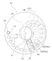
位置決め機構29は、図7に示すように、操作部材24の移動位置(回動位置)を複数段階(例えば、4−10段階、第1実施形態では10段階)に位置決め可能である。位置決め機構29は、位置決めピン70と、位置決めピン70が位置決めされる複数の位置決め凹部72と、位置決めピン70を位置決め凹部72に向けて付勢する付勢部材74と、を有する。位置決めピン70および付勢部材74は、軸支持部36の収納穴36eに装着される。複数の位置決め凹部72は、環状部材60の内側面のカム溝66aと反対側で外周側に周方向に間隔を隔てて、例えば、10個配置される。これによって、操作部材24を10段階に位置決めできる。位置決め凹部72は、例えば、円柱状または球状に凹んで形成される。第1実施形態では、位置決め凹部72は、球状に凹んで配置される。位置決めピン70は、先端部が球状に丸められる。位置決めピン70は、位置決め凹部72に対抗して配置される。
As shown in FIG. 7 , the
このような構成の連動機構26及び位置決め機構29では、図7に示すように、操作部材24が図7に示す第1位置に配置された状態で、操作部材24を第2軸X2の反時計方向の第1操作方向OD1に操作すると、連動機構26のカム66(カム溝66a)がカムフォロア68(突起部68a)を押圧し、移動部材20が第1軸X1回りの反時計方向に回転する。このとき、操作部材24は、10個の周方向位置で位置決めされる。これによって、回転検出部19の出力電圧が変化し、移動部材20の回動位置を検出できる。スプール制御部28では、検出された回転位置によって、スプール制動部22の制動力を調整する。
In the
ここでは、第1軸X1回りに回動する移動部材20と、第2軸X2回りに回動する操作部材24との間に連動機構26を設けることによって、操作部材24の配置の自由度が高くなる。このため、電気的に制御可能なスプール制動部22を有する両軸受リール10において、両軸受リール10の大きさにかかわらず一種類の回路基板18を使用できるようになる。
Here, by providing the
<第1実施形態の変形例>
なお、以降の説明では、第1実施形態と同じ構成の部材には同じ符号を付して説明を省略し、構成は異なるが作用が同じ部材は下二桁が第1実施形態と同じ三桁の符号を付して説明する。
<Modification of First Embodiment>
In the following description, members having the same configuration as in the first embodiment are denoted by the same reference numerals, and description thereof will be omitted. For members having a different configuration but the same operation, the lower two digits have the same three digits as in the first embodiment. The description will be given with reference numerals.
第1実施形態では、操作部材24は一つであったが、図8に示す変形例の両軸受リール110では、第1操作部材124aと第2操作部材124bとが設けられる。第1操作部材124aは、第1操作部本体158aと第1環状部材160aとを有する。第2操作部材124bは、第2操作部本体158bと第2環状部材160bとを有する。ここで、第1操作部材124aは、制動力の時間変化が異なる複数(例えば4つ)の制動モードのいずれかを選択するために設けられる。この実施形態では、例えば、釣り糸の種類(たとえば、ナイロンライン、フロロカーボンライン(ポリフッ化ビニリデン製の糸)、PEライン(ポリエチレン繊維を縒り合わせた糸))に応じた3つの制動モード及びオート制動モードの4つの制動モードのいずれかに調整できる。また、第2操作部材124bは、強さが異なる複数の制動力のいずれかを選択するために設けられる。この実施形態では、例えば、制動力の強さを8段階に調整可能である。
In the first embodiment, the number of the
回路基板118は、第1回転検出部119aと第2回転検出部119bと、を有する。第1回転検出部119aには、第1移動部材120aが一体回転可能に連結される。第2回転検出部119bには、第2移動部材120bが一体回転可能に連結される。また、軸支持部136は、第1連動機構126aを装着するための第1連動機構装着部136b1と、第2連動機構126bを装着するための第2連動機構装着部136b2と、を有する。
The
図8及び図9に示すように、第1連動機構126aは、第1カム機構164aを有する。第1カム機構164aは、第1移動部材120aに設けられる第1カムフォロア168aと、第1環状部材160aに設けられる第1カム166aとを有する。第1カム166aは、第1環状部材160aの内側面に、径方向に沿って延びる第1カム溝166a1を有する。第1カムフォロア168aは、第1移動部材120aに設けられる第1突起部168a1を有する。なお、図9では、位置決め数が多い第2連動機構126bを図示している。
As shown in FIGS. 8 and 9, the
第2連動機構126bは、第2カム機構164bを有する。第2カム機構164bは、第2移動部材120bに設けられる第2カムフォロア168bと、第2環状部材160bに設けられる第2カム166bとを有する。第2カム166bは、第2環状部材160bの内側面に、径方向に沿って延びる第2カム溝166a2を有する。第2カムフォロア168bは、第2移動部材120bに設けられる第2突起部168a2を有する。
The
両軸受リール110は、第1操作部材124aを、例えば4つの周方向位置に位置決めする第1位置決め機構129aと、第2操作部材124bを、例えば8つの周方向位置に位置決めする第2位置決め機構129bとがさらに設けられる。その他の両軸受リール110の構成は、第1実施形態と同様なため説明を省略する。
The
このような構成の両軸受リール110では、第1操作部材124aと第2操作部材124bとが設けられるので、制動力をさらに細かく調整できる。
In the dual-
<第2実施形態>
第2実施形態では、図10及び図11に示すように、スプール動作機構としてのスプール駆動部222を有する両軸受リール210について説明する。
<Second embodiment>
In the second embodiment, as shown in FIGS. 10 and 11, a dual-
両軸受リール210は、リール本体212と、ハンドル214と、糸巻き用のスプール216と、回転検出部19を有する回路基板218と、少なくとも一つの移動部材20(図10参照)と、モータ222aを含むスプール駆動部222(図12参照)と、操作部材224と、連動機構26と、スプール制御部228(図12参照)と、位置決め機構29と、を備える。したがって、第2実施形態の両軸受リール210では、第1実施形態と実質的に同じ構成の、回転検出部19、移動部材20、連動機構26、及び位置決め機構29を有する。操作部材224は、モータ222aの回転状態を調整するために設けられる。操作部材224は、外側面で操作するのではなく外周面で操作する点が第1実施形態と異なる。操作部材224は、スプール216の回転速度を複数段階に調整するために設けられる。
The dual-
リール本体212は、間隔をあけて対向して配置された第1側板230a及び第2側板230bを有するフレーム230と、第1側カバー232と、第2側カバー234と、カウンターケース236と、を有する。第1側カバー232は、ハンドル214側の第1側板230aの外側面を覆う。第2側カバー234は、第2側板230bの外側を覆う。カウンターケース236は、フレーム230の上部に配置される。カウンターケース236は、釣り糸の先端に取り付けられる仕掛けの水深を表示する、例えば液晶ディスプレイからなる表示器223を有する。カウンターケース236には、回路基板218が収納される。回路基板218は、表示器223及びスプール制御部228が搭載される第1回路基板218aと、回転検出部19を有し、第1回路基板218aと電気的に接続された第2回路基板218bとを有する。第2回路基板218bは、カウンターケース236のハンドル214側の後部に設けられる。フレーム230は、スプール216よりも前方に第1側板230aと第2側板230bを連結する筒状のモータ収納部230cを有する。
The
モータ収納部230cにモータ222aが収納されて固定される。モータ222aは、ハンドル214側で図示しない回転伝達機構を経由してスプール216を糸巻き取り方向に回転駆動する。
The
スプール駆動部222は、図12に示すように、モータ収納部230cに収納されたモータ222aと、モータ222aをパルス幅変調駆動するモータドライバ222bと、を有する。モータドライバ222bは、カウンターケース236に収容された複数の電界効果トランジスタによって構成される。
As shown in FIG. 12, the
スプール制御部228は、図12に示すように、ROM,RAM,CPUを含むマイクロコンピュータで構成される制御部228aと、EEPROM、フラッシュメモリなどの不揮発メモリによって構成される記憶部228bと、を有する。スプール制御部228には、スプールセンサ221と、回転検出部19と、が電気的に接続される。スプールセンサ221は、スプール216の回転速度、スプール216の総回転数などの検出に用いられる。回転検出部19は、移動部材20の回動位置を検出する。
As shown in FIG. 12, the
スプール制御部228は、ソフトウェアによって、回転検出部19が検出した移動部材20の移動位置に応じてモータドライバ222bを介してモータ222aをパルス幅変調制御する。また、スプール制御部228は、カウンターケース236に設けられる表示器223の表示制御も行う。
The
このように構成された電動の両軸受リール210では、操作部材224を第2軸X2回りの反時計方向の第1操作方向OD1に操作すると、連動機構26のカム66(カム溝66a)がカムフォロア68(突起部68a)を押圧し、移動部材20が第1軸X1回りの反時計方向に回転する。このとき、操作部材24は、複数個(例えば10個)の周方向位置で位置決めされる。これによって、回転検出部19の出力電圧が変化し、移動部材20の回動位置を検出できる。
In the electric dual-
<特徴>
上記実施形態は、下記のように表現可能である。
<Features>
The above embodiment can be expressed as follows.
(A)両軸受リール10は、釣り糸を前方に繰り出す。両軸受リール10は、リール本体12と、糸巻き用のスプール16と、回路基板18と、少なくとも一つの移動部材20と、スプール制動部22と、少なくとも一つの操作部材24と、連動機構26と、スプール制御部28と、を備える。糸巻き用のスプール16は、リール本体12に回転自在に設けられる。回路基板18は、第1軸X1回りの回動位置を検出可能な少なくとも一つの回転検出部19を有する。少なくとも一つの移動部材20は、回転検出部19によって回動位置が検出される。スプール制動部22は、スプール16に対して電気的に制御可能に動作し、移動部材20によって動作状態を調整可能である。少なくとも一つの操作部材24は、リール本体12に移動可能に設けられ、スプール制動部22の動作状態を調整操作するように構成される。連動機構26は、操作部材24の移動に応じて移動部材20を回転させる。スプール制御部28は、移動部材20の回動位置に応じてスプール制動部22を制御する。
(A) The
この両軸受リール10では、操作部材24を操作して移動させると、連動機構26によって移動部材20は操作部材24と連動して第1軸X1回りに回転する。移動部材20が回転すると回転検出部19が移動部材20の回動位置を検出し、スプール制御部28がスプール制動部22を移動部材20の回動位置に応じて制御する。ここでは、回転検出部19が検出する移動部材20を、操作部材24に直接連結するのではなく、連動機構26を介して操作部材24に連結したので、移動部材20、回転検出部19及び回路基板18を、異なる大きさの両軸受リールにおいて共通化できる。このため、両軸受リール10の大きさにかかわらず一種類の回路基板を使用できるようになる。
In the dual-bearing
(B)操作部材24は、リール本体12に第1軸X1と平行に設けられた第2軸X2回りに回動可能に設けられてもよい。この構成によれば、操作部材24も回動するので、連動機構26の構成を簡素化できる。
(B) The
(C)連動機構26は、操作部材24の移動に連動して移動部材20を回動させるカム機構64を有してもよい。この構成によれば、カム66とカムフォロア68とを有するカム機構64によって連動機構26を構成できるので、連動機構26の構成をさらに簡素化できる。
(C) The
(D)移動部材20は、操作部材24と径方向に重複して配置されてもよい。この構成によれば、移動部材20と操作部材24とを径方向に重複して配置するので、両軸受リール10の径方向の大きさをコンパクトに構成できる。
(D) The moving
(E)スプール制動部22は、回路基板18に装着されるコイル50と、スプールに一体回転可能に設けられた制動磁石48と、を有し、スプール16を制動する。移動部材20は、回路基板18に第1軸X1回りに回動可能に設けられ、操作部材24は、リール本体12に第2軸X2回りに回動可能に設けられてもよい。この構成によれば、コイル50に流れる電流を制御することによって、スプール16を制動するスプール制動部22において、両軸受リール10の大きさにかかわらず一種類の回路基板18を使用できるようになる。
(E) The
(F)スプール駆動部222は、リール本体212に固定されたモータ222aを有し、モータ222aによってスプール216を回転駆動する。操作部材224は、リール本体212に第2軸X2回りに回動可能に設けられてもよい。この構成によれば、モータ222aによってスプール216を回転駆動するスプール駆動部222において、両軸受リール210の大きさにかかわらず一種類の回路基板218を使用できるようになる。
(F) The
(G)カム機構64は、移動部材20及び操作部材24の一方に設けられるカム66と、移動部材20及び操作部材24の他方に設けられ、カム66に係合するカムフォロア68と、を有してもよい。この構成によれば、カム機構64によって、連動機構26を簡素な構成によって実現できる。
(G) The
(H)カム66は、径方向に沿って形成されたカム溝66aを有してもよい。カムフォロア68は、第1軸X1と離反した位置に第1軸X1と平行に配置され、カム溝66aの壁面に接触可能な突起部68aを有してもよい。この構成によれば、突起部68aをカム溝66aに係合させることによって、操作部材24の第2軸X2回りの回転を、移動部材20の第1軸X1回りの回転に容易に伝達できる。
(H) The
(I)両軸受リール10は、操作部材24の移動位置を複数段階に位置決め可能な位置決め機構29をさらに備えてもよい。この構成によれば、操作部材24が位置決めされるので、スプール制動部22の動作状態を再現しやすくなる。
(I) The dual-bearing
<他の実施形態>
以上、本発明の一実施形態について説明したが、本発明は上記実施形態に限定されるものではなく、発明の要旨を逸脱しない範囲で種々の変更が可能である。特に、本明細書に書かれた複数の実施形態及び変形例は必要に応じて任意に組合せ可能である。
<Other embodiments>
As described above, one embodiment of the present invention has been described, but the present invention is not limited to the above embodiment, and various changes can be made without departing from the gist of the invention. In particular, a plurality of embodiments and modifications described in this specification can be arbitrarily combined as needed.
(a)上記実施形態では、ポテンショメータとして、センサ部19cが可変抵抗によって構成されたが、本発明はこれに限定されない。センサ部をホール素子と磁石とで構成してもよい。この場合、制動磁石48による磁界の影響を受けないようにするために、ケース19aを磁束遮蔽部材によって構成してもよい。また、デジタルポテンショメータまたはロータリエンコーダを用いてもよい。
(A) In the above-described embodiment, the
(b)第2実施形態では、スプール動作機構として、スプール216をモータ222aによって駆動するスプール駆動部222を開示したが、スプール動作機構としてモータを用いたドラグ機構であってもよい。
(B) In the second embodiment, the
(c)上記実施形態では、連動機構26をカム機構64によって構成したが、連動機構26はカム機構64に限定されない。例えば、移動部材と操作部材をリンク機構によって連結してもよい。
(C) In the above embodiment, the interlocking
(d)上記実施形態では、連動機構26(または126)のカム機構64において、カム66を操作部材24に設け、カムフォロア68を移動部材に設けたが逆でもよい。
(D) In the above embodiment, in the
(e)上記実施形態では操作部材24を回動自在に構成したが、本発明はこれに限定されない。操作部材は、揺動及びスライドなどの移動であってもよい。
(E) In the above embodiment, the
10、110,210 両軸受リール
12、212 リール本体
16、216スプール
18、118,218 回路基板
19、219 回転検出部
19a ケース
19b 軸部材
19c センサ部
20、220 移動部材
22 スプール制動部
24、224 操作部材
26 連動機構
28、228 スプール制御部
29 位置決め機構
48 制動磁石
50 コイル
64 カム機構
66 カム
66a カム溝
68 カムフォロア
68a 突起部
119a 第1回転検出部
119b 第2回転検出部
120a 第1移動部材
120b 第2移動部材
124a 第1操作部材
124b 第2操作部材
126a 第1連動機構
126b 第2連動機構
129a 第1位置決め機構
129b 第2位置決め機構
164a 第1カム機構
164b 第2カム機構
166a :第1カム
166a1 第1カム溝
166a2 第2カム溝
166b 第2カム
168a 第1カムフォロア
168a1 第1突起部
168a2 第2突起部
168b 第2カムフォロア
218 回路基板
221 スプールセンサ
222 スプール駆動部
222a モータ
228 スプール制御部
X1 :第1軸
X2 :第2軸
10, 110, 210 Dual-bearing
Claims (8)
リール本体と、
前記リール本体に回転自在に設けられる糸巻き用のスプールと、
第1軸回りの回動位置を検出可能な少なくとも一つの回転検出部を有する回路基板と、
前記回転検出部によって回動位置が検出される少なくとも一つの移動部材と、
前記スプールに対して電気的に制御可能に動作し、前記移動部材によって動作状態を調整可能なスプール動作機構と、
前記リール本体に移動可能に設けられ、前記スプール動作機構の前記動作状態を調整操作するように構成される少なくとも一つの操作部材と、
前記操作部材の移動に応じて前記移動部材を回転させる連動機構と、
前記移動部材の回動位置に応じて前記スプール動作機構を制御するスプール制御部と、
を備え、
前記操作部材は、前記リール本体に前記第1軸と平行に設けられた第2軸回りに回動可能に設けられ、
前記移動部材は、前記操作部材と径方向に重複して配置される、両軸受リール。 A dual-bearing reel that feeds fishing line forward,
A reel body,
A spool for thread winding provided rotatably on the reel body,
A circuit board having at least one rotation detection unit capable of detecting a rotation position around the first axis;
At least one moving member whose rotation position is detected by the rotation detection unit,
A spool operation mechanism that operates electrically controllable with respect to the spool, and is capable of adjusting an operation state by the moving member,
At least one operation member movably provided on the reel body and configured to adjust the operation state of the spool operation mechanism;
An interlocking mechanism that rotates the moving member in accordance with the movement of the operating member,
A spool control unit that controls the spool operation mechanism according to a rotation position of the moving member;
Equipped with a,
The operating member is provided on the reel body so as to be rotatable around a second axis provided in parallel with the first axis,
The dual-bearing reel , wherein the moving member is arranged to overlap the operation member in a radial direction .
リール本体と、 A reel body,
前記リール本体に回転自在に設けられる糸巻き用のスプールと、 A spool for thread winding provided rotatably on the reel body,
第1軸回りの回動位置を検出可能な少なくとも一つの回転検出部を有する回路基板と、 A circuit board having at least one rotation detection unit capable of detecting a rotation position around the first axis;
前記回転検出部によって回動位置が検出される少なくとも一つの移動部材と、 At least one moving member whose rotation position is detected by the rotation detection unit,
前記スプールに対して電気的に制御可能に動作し、前記移動部材によって動作状態を調整可能なスプール動作機構と、 A spool operation mechanism that operates electrically controllable with respect to the spool and that can adjust an operation state by the moving member;
前記リール本体に移動可能に設けられ、前記スプール動作機構の前記動作状態を調整操作するように構成される少なくとも一つの操作部材と、 At least one operation member movably provided on the reel body and configured to adjust the operation state of the spool operation mechanism;
前記操作部材の移動に応じて前記移動部材を回転させる連動機構と、 An interlocking mechanism that rotates the moving member according to the movement of the operating member,
前記移動部材の回動位置に応じて前記スプール動作機構を制御するスプール制御部と、 A spool control unit that controls the spool operation mechanism according to a rotation position of the moving member;
を備え、With
前記操作部材は、前記リール本体に前記第1軸と平行に設けられた第2軸回りに回動可能に設けられ、 The operation member is provided on the reel body so as to be rotatable around a second axis provided in parallel with the first axis,
前記連動機構は、前記操作部材の移動に連動して前記移動部材を回動させるカム機構を有する、両軸受リール。 The dual bearing reel, wherein the interlocking mechanism has a cam mechanism that rotates the moving member in conjunction with the movement of the operation member.
前記移動部材及び前記操作部材の一方に設けられるカムと、
前記移動部材及び前記操作部材の他方に設けられ、前記カムに係合するカムフォロアと、
を有する、請求項2又は3に記載の両軸受リール。 The cam mechanism,
A cam provided on one of the moving member and the operating member,
A cam follower provided on the other of the moving member and the operating member and engaging with the cam;
The dual- bearing reel according to claim 2 , comprising:
前記カムフォロアは、前記移動部材に前記第1軸と離反した位置に前記第1軸と平行に配置され、前記カム溝の壁面に接触可能な突起部を有する、請求項4に記載の両軸受リール。 The cam has a cam groove formed in the operation member along a radial direction,
5. The dual-bearing reel according to claim 4 , wherein the cam follower is disposed on the moving member at a position away from the first axis and parallel to the first axis, and has a protrusion that can contact a wall surface of the cam groove. 6. .
前記回転検出部は、ケースと、前記ケースに前記第1軸回りに回動自在に支持された軸部材と、前記ケース内に設けられ、前記軸部材の回動位置を検出可能なセンサ部とを有し、
前記移動部材は、前記軸部材に前記第1軸回りに一体的に回動可能に設けられる、請求項1から5のいずれか1項に記載の両軸受リール。 The spool operation mechanism is a spool braking unit that includes a coil mounted on the circuit board and a magnet that is integrally rotatable with the spool, and that brakes the spool.
The rotation detection unit includes a case, a shaft member rotatably supported on the case around the first axis, and a sensor unit provided in the case and capable of detecting a rotation position of the shaft member. Has,
The dual-bearing reel according to any one of claims 1 to 5, wherein the moving member is provided on the shaft member so as to be integrally rotatable around the first shaft.
前記操作部材は、前記リール本体に前記第2軸回りに回動可能に設けられる、請求項1から5のいずれか1項に記載の両軸受リール。 The spool operation mechanism has a motor fixed to the reel body, a spool drive unit that drives the spool to rotate by the motor,
The dual bearing reel according to any one of claims 1 to 5, wherein the operation member is provided on the reel body so as to be rotatable around the second axis.
Priority Applications (6)
| Application Number | Priority Date | Filing Date | Title |
|---|---|---|---|
| JP2016008320A JP6653582B2 (en) | 2016-01-19 | 2016-01-19 | Double bearing reel |
| TW105139087A TWI684404B (en) | 2016-01-19 | 2016-11-28 | Dual-bearing reel |
| KR1020160165850A KR102611459B1 (en) | 2016-01-19 | 2016-12-07 | Dual-bearing reel |
| US15/374,721 US10271530B2 (en) | 2016-01-19 | 2016-12-09 | Dual-bearing reel |
| MYPI2016704647A MY180387A (en) | 2016-01-19 | 2016-12-15 | Dual-bearing reel |
| CN201710034663.9A CN106973872B (en) | 2016-01-19 | 2017-01-18 | Dual-bearing reel |
Applications Claiming Priority (1)
| Application Number | Priority Date | Filing Date | Title |
|---|---|---|---|
| JP2016008320A JP6653582B2 (en) | 2016-01-19 | 2016-01-19 | Double bearing reel |
Publications (3)
| Publication Number | Publication Date |
|---|---|
| JP2017127233A JP2017127233A (en) | 2017-07-27 |
| JP2017127233A5 JP2017127233A5 (en) | 2018-12-27 |
| JP6653582B2 true JP6653582B2 (en) | 2020-02-26 |
Family
ID=59313452
Family Applications (1)
| Application Number | Title | Priority Date | Filing Date |
|---|---|---|---|
| JP2016008320A Active JP6653582B2 (en) | 2016-01-19 | 2016-01-19 | Double bearing reel |
Country Status (6)
| Country | Link |
|---|---|
| US (1) | US10271530B2 (en) |
| JP (1) | JP6653582B2 (en) |
| KR (1) | KR102611459B1 (en) |
| CN (1) | CN106973872B (en) |
| MY (1) | MY180387A (en) |
| TW (1) | TWI684404B (en) |
Families Citing this family (9)
| Publication number | Priority date | Publication date | Assignee | Title |
|---|---|---|---|---|
| JP7013809B2 (en) * | 2017-11-15 | 2022-02-01 | 株式会社三洋物産 | Pachinko machine |
| JP7013810B2 (en) * | 2017-11-15 | 2022-02-01 | 株式会社三洋物産 | Pachinko machine |
| JP2019088591A (en) * | 2017-11-15 | 2019-06-13 | 株式会社三洋物産 | Game machine |
| JP2019088592A (en) * | 2017-11-15 | 2019-06-13 | 株式会社三洋物産 | Game machine |
| JP7262167B2 (en) * | 2017-11-22 | 2023-04-21 | 株式会社シマノ | Double bearing reel |
| JP6941560B2 (en) | 2017-12-28 | 2021-09-29 | 株式会社シマノ | Bearing accommodation structure and double bearing reel |
| JP7049940B2 (en) * | 2018-06-21 | 2022-04-07 | 株式会社シマノ | Double bearing reel |
| JP7094169B2 (en) * | 2018-07-13 | 2022-07-01 | 株式会社シマノ | Double bearing reel |
| JP7166895B2 (en) * | 2018-11-28 | 2022-11-08 | 株式会社シマノ | REEL BRAKE ADJUSTMENT DEVICE AND REEL BRAKE ADJUSTMENT PROGRAM |
Family Cites Families (25)
| Publication number | Priority date | Publication date | Assignee | Title |
|---|---|---|---|---|
| JPS58155036A (en) * | 1982-03-09 | 1983-09-14 | 株式会社シマノ | Dual bearing reel |
| JPS6125773U (en) * | 1984-07-20 | 1986-02-15 | ダイワ精工株式会社 | Fishing reel spool rotation detection device |
| US5397071A (en) * | 1993-07-26 | 1995-03-14 | Daiwa Seiko, Inc. | Motor-operated fishing reel |
| JPH07213203A (en) * | 1994-01-28 | 1995-08-15 | Daiwa Seiko Inc | Fishing reel |
| US6045076A (en) * | 1995-08-03 | 2000-04-04 | Daniels; John J. | Fishing reel with electronic antibacklashing features dependent on a sensed line condition |
| JPH10178984A (en) * | 1996-12-27 | 1998-07-07 | Ryobi Ltd | Motor-driven reel for fishing |
| JPH1118641A (en) * | 1997-07-09 | 1999-01-26 | Daiwa Seiko Inc | Electric reel for fishing |
| JPH11332436A (en) * | 1998-05-13 | 1999-12-07 | Johnson Worldwide Assoc Inc | Bait casting control fishing reel |
| SG121857A1 (en) * | 2003-01-06 | 2006-05-26 | Shimano Kk | Braking device for a dual bearing reel |
| JP4384876B2 (en) | 2003-06-05 | 2009-12-16 | 株式会社シマノ | Electronic equipment for fishing gear |
| SG125114A1 (en) * | 2003-05-13 | 2006-09-29 | Shimano Kk | Electronic circuit device for fishing equipment |
| US7150423B2 (en) * | 2003-09-12 | 2006-12-19 | Shimano Inc. | Reel unit for a dual bearing reel |
| JP4362384B2 (en) * | 2004-02-02 | 2009-11-11 | 株式会社シマノ | Dual bearing reel and spool brake device used therefor |
| JP5122273B2 (en) * | 2007-12-28 | 2013-01-16 | 株式会社シマノ | Spool braking device for double-bearing reel |
| US7712695B2 (en) * | 2008-07-10 | 2010-05-11 | Freescale Semiconductor, Inc. | Spool braking device for fishing reel |
| TWM359203U (en) * | 2008-12-02 | 2009-06-21 | Tsung-Liang Chang | Winder with multi-directional rotation spool |
| US8602343B2 (en) * | 2009-04-23 | 2013-12-10 | James R. Strohecker | Fishing reel with free spool controller |
| JP5746841B2 (en) * | 2010-09-22 | 2015-07-08 | 株式会社シマノ | Clutch control device for double bearing reel |
| JP5752497B2 (en) * | 2011-06-23 | 2015-07-22 | グローブライド株式会社 | Fishing electric reel |
| JP2013005738A (en) * | 2011-06-23 | 2013-01-10 | Globeride Inc | Electric reel for fishing |
| JP5944742B2 (en) * | 2012-05-17 | 2016-07-05 | 株式会社シマノ | Spool brake device for double-bearing reel and double-bearing reel |
| JP6085447B2 (en) * | 2012-10-19 | 2017-02-22 | 株式会社シマノ | Spool braking device for double-bearing reel |
| JP6247834B2 (en) * | 2012-11-19 | 2017-12-13 | 株式会社シマノ | Electric reel |
| KR102099663B1 (en) * | 2012-11-19 | 2020-05-15 | 가부시키가이샤 시마노 | Electrical fishing reel |
| JP6335528B2 (en) * | 2014-01-28 | 2018-05-30 | 株式会社シマノ | Reel body of double-bearing reel |
-
2016
- 2016-01-19 JP JP2016008320A patent/JP6653582B2/en active Active
- 2016-11-28 TW TW105139087A patent/TWI684404B/en active
- 2016-12-07 KR KR1020160165850A patent/KR102611459B1/en active IP Right Grant
- 2016-12-09 US US15/374,721 patent/US10271530B2/en active Active
- 2016-12-15 MY MYPI2016704647A patent/MY180387A/en unknown
-
2017
- 2017-01-18 CN CN201710034663.9A patent/CN106973872B/en active Active
Also Published As
| Publication number | Publication date |
|---|---|
| KR20170087015A (en) | 2017-07-27 |
| CN106973872B (en) | 2021-05-25 |
| MY180387A (en) | 2020-11-28 |
| TWI684404B (en) | 2020-02-11 |
| KR102611459B1 (en) | 2023-12-08 |
| US10271530B2 (en) | 2019-04-30 |
| CN106973872A (en) | 2017-07-25 |
| JP2017127233A (en) | 2017-07-27 |
| TW201725978A (en) | 2017-08-01 |
| US20170202192A1 (en) | 2017-07-20 |
Similar Documents
| Publication | Publication Date | Title |
|---|---|---|
| JP6653582B2 (en) | Double bearing reel | |
| JP2017127233A5 (en) | ||
| US10271529B2 (en) | Fishing reel | |
| US10039272B2 (en) | Spool brake device for dual-bearing reel | |
| US7165737B2 (en) | Spool braking device for dual-bearing reel | |
| US7503517B2 (en) | Spool braking device for dual bearing reel | |
| JP2017127286A5 (en) | ||
| TWI583306B (en) | Double bearing type reel | |
| JP2006197810A (en) | Spool braking device of double bering reel | |
| JP2006197810A5 (en) | ||
| US10159234B2 (en) | Fishing reel | |
| KR20090072950A (en) | Dual bearing reel | |
| JP2017127285A5 (en) | ||
| JP6342218B2 (en) | Electric reel motor control device | |
| JP6795990B2 (en) | Spool braking device | |
| JP2023032405A (en) | Braking device braking spool and fishing reel provided with the same | |
| JP6284307B2 (en) | Electric reel motor control device | |
| JP2015002689A5 (en) | ||
| JP7260507B2 (en) | electric fishing reel | |
| JP2004208631A (en) | Braking device of double-bearing reel | |
| KR20230031789A (en) | Braking device that brakes spool and fishing reel provided with the same | |
| JP2023032403A (en) | Braking device braking spool and fishing reel provided with the same |
Legal Events
| Date | Code | Title | Description |
|---|---|---|---|
| A521 | Request for written amendment filed |
Free format text: JAPANESE INTERMEDIATE CODE: A523 Effective date: 20181112 |
|
| A621 | Written request for application examination |
Free format text: JAPANESE INTERMEDIATE CODE: A621 Effective date: 20181112 |
|
| A977 | Report on retrieval |
Free format text: JAPANESE INTERMEDIATE CODE: A971007 Effective date: 20190712 |
|
| A131 | Notification of reasons for refusal |
Free format text: JAPANESE INTERMEDIATE CODE: A131 Effective date: 20190723 |
|
| A521 | Request for written amendment filed |
Free format text: JAPANESE INTERMEDIATE CODE: A523 Effective date: 20190909 |
|
| TRDD | Decision of grant or rejection written | ||
| A01 | Written decision to grant a patent or to grant a registration (utility model) |
Free format text: JAPANESE INTERMEDIATE CODE: A01 Effective date: 20200121 |
|
| A61 | First payment of annual fees (during grant procedure) |
Free format text: JAPANESE INTERMEDIATE CODE: A61 Effective date: 20200128 |
|
| R150 | Certificate of patent or registration of utility model |
Ref document number: 6653582 Country of ref document: JP Free format text: JAPANESE INTERMEDIATE CODE: R150 |
|
| R250 | Receipt of annual fees |
Free format text: JAPANESE INTERMEDIATE CODE: R250 |
|
| R250 | Receipt of annual fees |
Free format text: JAPANESE INTERMEDIATE CODE: R250 |