JP2015190898A - Defect detection apparatus and defect detection method - Google Patents
Defect detection apparatus and defect detection method Download PDFInfo
- Publication number
- JP2015190898A JP2015190898A JP2014069358A JP2014069358A JP2015190898A JP 2015190898 A JP2015190898 A JP 2015190898A JP 2014069358 A JP2014069358 A JP 2014069358A JP 2014069358 A JP2014069358 A JP 2014069358A JP 2015190898 A JP2015190898 A JP 2015190898A
- Authority
- JP
- Japan
- Prior art keywords
- image data
- color
- sewing product
- yarn
- sewing
- Prior art date
- Legal status (The legal status is an assumption and is not a legal conclusion. Google has not performed a legal analysis and makes no representation as to the accuracy of the status listed.)
- Granted
Links
Images


Classifications
-
- D—TEXTILES; PAPER
- D05—SEWING; EMBROIDERING; TUFTING
- D05B—SEWING
- D05B51/00—Applications of needle-thread guards; Thread-break detectors
-
- G—PHYSICS
- G01—MEASURING; TESTING
- G01N—INVESTIGATING OR ANALYSING MATERIALS BY DETERMINING THEIR CHEMICAL OR PHYSICAL PROPERTIES
- G01N21/00—Investigating or analysing materials by the use of optical means, i.e. using sub-millimetre waves, infrared, visible or ultraviolet light
- G01N21/84—Systems specially adapted for particular applications
- G01N21/88—Investigating the presence of flaws or contamination
- G01N21/8806—Specially adapted optical and illumination features
-
- G—PHYSICS
- G01—MEASURING; TESTING
- G01N—INVESTIGATING OR ANALYSING MATERIALS BY DETERMINING THEIR CHEMICAL OR PHYSICAL PROPERTIES
- G01N21/00—Investigating or analysing materials by the use of optical means, i.e. using sub-millimetre waves, infrared, visible or ultraviolet light
- G01N21/84—Systems specially adapted for particular applications
- G01N21/88—Investigating the presence of flaws or contamination
- G01N21/95—Investigating the presence of flaws or contamination characterised by the material or shape of the object to be examined
-
- D—TEXTILES; PAPER
- D05—SEWING; EMBROIDERING; TUFTING
- D05D—INDEXING SCHEME ASSOCIATED WITH SUBCLASSES D05B AND D05C, RELATING TO SEWING, EMBROIDERING AND TUFTING
- D05D2305/00—Operations on the work before or after sewing
- D05D2305/32—Measuring
- D05D2305/36—Quality control
-
- G—PHYSICS
- G01—MEASURING; TESTING
- G01N—INVESTIGATING OR ANALYSING MATERIALS BY DETERMINING THEIR CHEMICAL OR PHYSICAL PROPERTIES
- G01N21/00—Investigating or analysing materials by the use of optical means, i.e. using sub-millimetre waves, infrared, visible or ultraviolet light
- G01N21/84—Systems specially adapted for particular applications
- G01N21/88—Investigating the presence of flaws or contamination
- G01N21/8806—Specially adapted optical and illumination features
- G01N2021/8845—Multiple wavelengths of illumination or detection
Abstract
Description
本発明は、縫製品に用いられている縫い糸に生じた欠陥を検出する欠陥検出装置及び欠陥検出方法に関する。 The present invention relates to a defect detection apparatus and a defect detection method for detecting a defect generated in a sewing thread used in a sewing product.
エアバッグ等の縫製品を製造する過程で、縫い糸によって形成される縫い目に、糸のほつれや、糸切れ、目飛び等の欠陥が生じることがある。この様な欠陥は、従来、目視検査により検出されていた。近年、検出精度の更なる向上や、ランニングコストの低廉化のために、欠陥検出を自動化することが検討されている。具体的には、オペレータが検査テーブルに縫製品を置いた後、自動的に、縫製品の画像データが取得され、その画像データ、又はその画像データに画像処理を施すことにより生成された処理画像データに基づいて、縫い糸に生じた目飛び等の欠陥が検出される(例えば、特許文献1又は2参照)。
In the process of manufacturing a sewing product such as an airbag, defects such as thread fraying, thread breakage, and stitch skipping may occur in the seam formed by the sewing thread. Such a defect has been conventionally detected by visual inspection. In recent years, automating defect detection has been studied in order to further improve detection accuracy and reduce running costs. Specifically, after an operator places a sewing product on an inspection table, image data of the sewing product is automatically acquired, and the image data or a processed image generated by performing image processing on the image data Based on the data, a defect such as a stitch skip occurring in the sewing thread is detected (for example, see
しかし、縫製品において、縫い糸によって形成された2本の縫合線が互いに交差している場合、従来の欠陥検出技術では、縫合線の交差箇所での欠陥の有無を精度良く判定することが困難であった。 However, in a sewn product, when two suture lines formed by sewing threads intersect each other, it is difficult to accurately determine the presence or absence of defects at the intersections of the suture lines with the conventional defect detection technology. there were.
又、縫製品において、縫い糸である上糸と下糸とが互いに絡み合っている場合、上糸及び下糸の何れか一方の縫い糸に欠陥が生じていたとしても、従来の欠陥検出技術では、欠陥を精度良く検出することが困難であった。例えば、画像データの処理時に、欠陥が、その欠陥を生じた縫い糸とは別の縫い糸により隠れる虞があった。 In addition, when the upper thread and the lower thread, which are sewing threads, are entangled with each other in the sewing product, even if one of the upper thread and the lower thread has a defect, the conventional defect detection technology does not It was difficult to accurately detect. For example, when processing image data, there is a possibility that the defect may be hidden by a sewing thread different from the sewing thread in which the defect has occurred.
そこで本発明の目的は、縫製品に用いられている縫い糸に生じた欠陥を高い精度で検出することが可能な欠陥検出装置及び欠陥検出方法を提供することである。 SUMMARY OF THE INVENTION An object of the present invention is to provide a defect detection device and a defect detection method capable of detecting a defect generated in a sewing thread used in a sewing product with high accuracy.
本発明は、縫製品において縫い糸として用いられた色糸が持つ分光反射率特性又は分光透過率特性を利用してなされたものである。具体的には、以下の通りである。 The present invention has been made by utilizing the spectral reflectance characteristic or spectral transmittance characteristic of the colored yarn used as a sewing thread in a sewn product. Specifically, it is as follows.
本発明に係る第1の欠陥検出装置は、第1の色糸と、第1の色糸とは色が異なる第2の色糸とが、縫い糸として用いられている縫製品において、縫い糸に生じた欠陥を検出する装置であって、照明部と、撮像部とを備える。照明部は、第1照明光を、縫製品の検査対象面に対して照射する。ここで、第1照明光は、第1の色糸が持つ分光反射率特性において反射率が低くて且つ第2の色糸が持つ分光反射率特性において第1の色糸よりも反射率が高い波長域と略同一の波長域を持った光である。撮像部は、縫製品の検査対象面を撮像する。そして、第1の欠陥検出装置は、照明部に、縫製品に対して第1照明光を照射させ、この状態で、撮像部に、縫製品の検査対象面を撮像させて縫製品の第1画像データを取得させる。又、第1の欠陥検出装置は、撮像部に取得させた第1画像データ、又は第1画像データに画像処理を施すことにより生成された処理画像データに基づいて、欠陥を検出する。 According to the first defect detection device of the present invention, a first colored thread and a second colored thread having a different color from the first colored thread are generated in the sewing thread in the sewing product used as the sewing thread. An apparatus for detecting a defect including an illumination unit and an imaging unit. An illumination part irradiates 1st illumination light with respect to the test object surface of a sewing product. Here, the first illumination light has a low reflectance in the spectral reflectance characteristic of the first color yarn and a higher reflectance than the first color yarn in the spectral reflectance characteristic of the second color yarn. It is light having a wavelength range substantially the same as the wavelength range. The imaging unit images the inspection target surface of the sewing product. Then, the first defect detection device causes the illumination unit to irradiate the sewing product with the first illumination light, and in this state, causes the imaging unit to image the inspection target surface of the sewing product, thereby causing the first sewing product to be imaged. Get image data. The first defect detection device detects a defect based on the first image data acquired by the imaging unit or the processed image data generated by performing image processing on the first image data.
本発明に係る第2の欠陥検出装置は、第1の色糸と、第1の色糸とは色が異なる第2の色糸とが、縫い糸として用いられている縫製品において、縫い糸に生じた欠陥を検出する装置であって、照明部と、撮像部とを備える。照明部は、第1照明光を、縫製品の検査対象面に対して縫製品の背後から照射する。ここで、第1照明光は、第1の色糸が持つ分光透過率特性において透過率が低くて且つ第2の色糸が持つ分光透過率特性において第1の色糸よりも透過率が高い波長域と略同一の波長域を持った光である。撮像部は、縫製品の検査対象面を撮像する。そして、第2の欠陥検出装置は、照明部に、縫製品に対して第1照明光を照射させ、この状態で、撮像部に、縫製品の検査対象面を撮像させて縫製品の第1画像データを取得させる。又、第2の欠陥検出装置は、撮像部に取得させた第1画像データ、又は第1画像データに画像処理を施すことにより生成された処理画像データに基づいて、欠陥を検出する。 According to a second defect detection device of the present invention, a first colored yarn and a second colored yarn having a different color from the first colored yarn are generated in a sewing thread in a sewing product that is used as a sewing thread. An apparatus for detecting a defect including an illumination unit and an imaging unit. An illumination part irradiates 1st illumination light from the back of a sewing product with respect to the test object surface of a sewing product. Here, the first illumination light has a low transmittance in the spectral transmittance characteristic of the first color yarn, and a higher transmittance than the first color yarn in the spectral transmittance characteristic of the second color yarn. It is light having a wavelength range substantially the same as the wavelength range. The imaging unit images the inspection target surface of the sewing product. Then, the second defect detection device causes the illumination unit to irradiate the sewing product with the first illumination light, and in this state, causes the imaging unit to image the inspection target surface of the sewing product and causes the first sewing product to be imaged. Get image data. The second defect detection device detects a defect based on the first image data acquired by the imaging unit or the processed image data generated by performing image processing on the first image data.
本発明に係る第1の欠陥検出方法は、第1の色糸と、第1の色糸とは色が異なる第2の色糸とが、縫い糸として用いられている縫製品において、縫い糸に生じた欠陥を検出する方法である。第1の欠陥検出方法では、先ず、第1の色糸が持つ分光反射率特性において反射率が低くて且つ第2の色糸が持つ分光反射率特性において第1の色糸よりも反射率が高い波長域と略同一の波長域を持った第1照明光を、縫製品の検査対象面に対して照射し、この状態で、縫製品の検査対象面を撮像して縫製品の第1画像データを取得する。次に、取得した第1画像データ、又は第1画像データに画像処理を施すことにより生成された処理画像データに基づいて、欠陥を検出する。 According to the first defect detection method of the present invention, a first colored yarn and a second colored yarn having a different color from the first colored yarn are generated in a sewing thread in a sewing product used as a sewing thread. This is a method for detecting a defect. In the first defect detection method, first, in the spectral reflectance characteristic of the first color yarn, the reflectance is low, and in the spectral reflectance characteristic of the second color yarn, the reflectance is higher than that of the first color yarn. First illumination light having substantially the same wavelength range as the high wavelength range is irradiated to the inspection target surface of the sewing product, and in this state, the inspection target surface of the sewing product is imaged to obtain a first image of the sewing product. Get the data. Next, a defect is detected based on the acquired first image data or processed image data generated by performing image processing on the first image data.
本発明に係る第2の欠陥検出方法は、第1の色糸と、第1の色糸とは色が異なる第2の色糸とが、縫い糸として用いられている縫製品において、縫い糸に生じた欠陥を検出する方法である。第2の欠陥検出方法では、先ず、第1の色糸が持つ分光透過率特性において透過率が低くて且つ第2の色糸が持つ分光透過率特性において第1の色糸よりも透過率が高い波長域と略同一の波長域を持った第1照明光を、縫製品の検査対象面に対して縫製品の背後から照射し、この状態で、縫製品の検査対象面を撮像して縫製品の第1画像データを取得する。次に、取得した第1画像データ、又は第1画像データに画像処理を施すことにより生成された処理画像データに基づいて、欠陥を検出する。 According to the second defect detection method of the present invention, a first colored yarn and a second colored yarn having a different color from the first colored yarn are generated in a sewing thread in a sewing product that is used as a sewing thread. This is a method for detecting a defect. In the second defect detection method, first, the transmittance in the spectral transmittance characteristic of the first color yarn is low and the transmittance in the spectral transmittance characteristic of the second color yarn is higher than that of the first color yarn. The first illumination light having the same wavelength range as the high wavelength range is irradiated from the back of the sewing product to the inspection target surface of the sewing product, and in this state, the inspection target surface of the sewing product is imaged and sewn. The first image data of the product is acquired. Next, a defect is detected based on the acquired first image data or processed image data generated by performing image processing on the first image data.
本発明に係る欠陥検出装置及び欠陥検出方法によれば、縫製品に用いられている縫い糸に生じた欠陥を高い精度で検出することが可能になる。 According to the defect detection device and the defect detection method according to the present invention, it is possible to detect a defect generated in a sewing thread used in a sewing product with high accuracy.
先ず、本発明の実施形態を列記して説明する。
本発明の実施形態に係る第1の欠陥検出装置は、第1の色糸と、第1の色糸とは色が異なる第2の色糸とが、縫い糸として用いられている縫製品において、縫い糸に生じた欠陥を検出する装置であって、照明部と、撮像部とを備える。照明部は、第1照明光を、縫製品の検査対象面に対して照射する。ここで、第1照明光は、第1の色糸が持つ分光反射率特性において反射率が低くて且つ第2の色糸が持つ分光反射率特性において第1の色糸よりも反射率が高い波長域と略同一の波長域を持った光である。撮像部は、縫製品の検査対象面を撮像する。そして、第1の欠陥検出装置は、照明部に、縫製品に対して第1照明光を照射させ、この状態で、撮像部に、縫製品の検査対象面を撮像させて縫製品の第1画像データを取得させる。又、第1の欠陥検出装置は、撮像部に取得させた第1画像データ、又は第1画像データに画像処理を施すことにより生成された処理画像データに基づいて、欠陥を検出する。
First, embodiments of the present invention will be listed and described.
In the first defect detection device according to the embodiment of the present invention, in the sewing product in which the first color yarn and the second color yarn having a color different from the first color yarn are used as the sewing yarn, An apparatus for detecting a defect generated in a sewing thread, comprising an illumination unit and an imaging unit. An illumination part irradiates 1st illumination light with respect to the test object surface of a sewing product. Here, the first illumination light has a low reflectance in the spectral reflectance characteristic of the first color yarn and a higher reflectance than the first color yarn in the spectral reflectance characteristic of the second color yarn. It is light having a wavelength range substantially the same as the wavelength range. The imaging unit images the inspection target surface of the sewing product. Then, the first defect detection device causes the illumination unit to irradiate the sewing product with the first illumination light, and in this state, causes the imaging unit to image the inspection target surface of the sewing product, thereby causing the first sewing product to be imaged. Get image data. The first defect detection device detects a defect based on the first image data acquired by the imaging unit or the processed image data generated by performing image processing on the first image data.
上記第1の欠陥検出装置によれば、第1照明光は、第2の色糸において高い割合で反射される。従って、縫製品の基材が、第1照明光の波長域の光に対する反射率が高いものである場合、取得される第1画像データにおいて、第2の色糸及び基材は、第1照明光と同系の色で写し出されることになる。よって、第1画像データでは、第2の色糸は、その背景となる基材に溶け込んだ状態となる。一方、第1照明光は、第1の色糸において高い割合で吸収される。よって、第1の色糸は、第1画像データにおいて黒色系の色(暗い色を含む)で写し出される。即ち、上記第1の欠陥検出装置は、第1の色糸を、第2の色糸と区別して抽出することが出来る。よって、上記第1の欠陥検出装置によれば、第1の色糸に生じた欠陥を高い精度で検出することが可能となる。 According to the first defect detection device, the first illumination light is reflected at a high rate in the second colored yarn. Therefore, when the base material of the sewing product has a high reflectance with respect to light in the wavelength range of the first illumination light, the second color yarn and the base material in the first image data acquired are the first illumination light. It will be projected in a color similar to light. Therefore, in the first image data, the second colored yarn is in a state of being melted into the base material as the background. On the other hand, the first illumination light is absorbed at a high rate in the first color yarn. Therefore, the first color thread is copied in black color (including dark color) in the first image data. That is, the first defect detection device can extract the first color yarn while distinguishing it from the second color yarn. Therefore, according to the first defect detection device, it is possible to detect a defect generated in the first colored yarn with high accuracy.
又、縫製品の基材が、第1照明光の波長域の光に対する反射率が低いものである場合、上記第1の欠陥検出装置によれば、取得される第1画像データにおいて、第1の色糸及び基材は、黒色系の色(暗い色を含む)で写し出され、その結果、第1の色糸は、その背景となる基材に溶け込んだ状態となる。一方、第2の色糸は、第1画像データにおいて第1照明光と同系の色で写し出される。即ち、上記第1の欠陥検出装置は、第2の色糸を、第1の色糸と区別して抽出することが出来る。よって、上記第1の欠陥検出装置によれば、第2の色糸に生じた欠陥を高い精度で検出することが可能となる。 In addition, when the base material of the sewing product has a low reflectance with respect to light in the wavelength range of the first illumination light, the first defect detection device provides the first image data obtained by The colored yarn and the base material are projected with a black color (including a dark color), and as a result, the first colored yarn is in a state of being melted into the background base material. On the other hand, the second colored yarn is projected in the same color as the first illumination light in the first image data. That is, the first defect detection device can extract the second color yarn in distinction from the first color yarn. Therefore, according to the first defect detection device, it is possible to detect a defect generated in the second colored yarn with high accuracy.
上記第1の欠陥検出装置の好ましい具体的構成において、第1の欠陥検出装置は、画像処理部と、欠陥検出部と、制御部とを更に備える。又、照明部は、第1及び第2の色糸がそれぞれ持つ分光反射率特性の何れにおいても反射率が低い波長域、又は第1及び第2の色糸がそれぞれ持つ分光反射率特性の何れにおいても反射率が高い波長域の何れかと略同一の波長域を持った第2照明光と、上記第1照明光とを、縫製品の検査対象面に対して選択的に照射することが可能である。そして、制御部は、制御(i)〜(iv)を実行する。制御(i)では、制御部は、照明部に、縫製品に対して第1照明光を照射させ、この状態で、撮像部に、縫製品の検査対象面を撮像させて縫製品の第1画像データを取得させる。制御(ii)では、制御部は、照明部に、縫製品に対して第2照明光を照射させ、この状態で、撮像部に、縫製品の検査対象面を撮像させて縫製品の第2画像データを取得させる。制御(iii)では、制御部は、画像処理部に、第1画像データ及び第2画像データに対する画像処理を実行させることにより、処理画像データを生成させる。このとき、画像処理部は、制御(i)で得られた第1画像データと、制御(ii)で得られた第2画像データとを用いることにより、第1及び第2の色糸のうちの何れか一方の色糸のみが抽出された画像データを、処理画像データとして生成する。制御(iv)では、制御部は、欠陥検出部に、処理画像データに基づいて欠陥を検出させる。尚、制御(iii)には、第1画像データ及び第2画像データの両方を用いて処理画像データを生成する場合に限らず、第1画像データのみを用いて処理画像データを生成する場合、更にはこれら2つの処理画像データを何れも生成する場合が含まれる。 In a preferred specific configuration of the first defect detection device, the first defect detection device further includes an image processing unit, a defect detection unit, and a control unit. In addition, the illuminating unit has either a wavelength region where the reflectance is low in any of the spectral reflectance characteristics of the first and second color yarns, or the spectral reflectance characteristics of the first and second color yarns. Can also selectively irradiate the surface to be inspected of the sewing product with the second illumination light having substantially the same wavelength region as any of the wavelength regions having high reflectivity and the first illumination light. It is. And a control part performs control (i)-(iv). In the control (i), the control unit causes the illuminating unit to irradiate the sewing product with the first illumination light, and in this state, causes the imaging unit to image the inspection target surface of the sewn product and causes the first sewn product to be imaged. Get image data. In the control (ii), the control unit causes the illuminating unit to irradiate the sewing product with the second illumination light, and in this state, causes the imaging unit to image the inspection target surface of the sewn product and causes the second sewn product to be imaged. Get image data. In the control (iii), the control unit causes the image processing unit to perform image processing on the first image data and the second image data, thereby generating processed image data. At this time, the image processing unit uses the first image data obtained by the control (i) and the second image data obtained by the control (ii), so that the first and second color yarns are used. Image data in which only one of the color threads is extracted is generated as processed image data. In the control (iv), the control unit causes the defect detection unit to detect a defect based on the processed image data. Note that the control (iii) is not limited to the case where the processed image data is generated using both the first image data and the second image data, but when the processed image data is generated using only the first image data. Furthermore, the case where both of these two processed image data are generated is included.
上記構成において、第2照明光が、第1及び第2の色糸の何れにおいても反射率が低い波長域を持った光であることが好ましい場合として、縫製品の基材が、第1照明光及び第2照明光の何れの波長域の光に対しても反射率が高いものである場合が考えられる。この場合、第2照明光は、第1及び第2の色糸の何れにおいても、高い割合で吸収される。従って、取得される第2画像データにおいて、基材が第2照明光と同系の色で写し出される一方で、第1及び第2の色糸は、黒色系の色(暗い色を含む)で写し出されることになる。一方、第1画像データでは、上述した様に、第1の色糸が黒色系の色(暗い色を含む)で写し出される一方で、第2の色糸は、その背景となる基材(第1照明光と同系の色)に溶け込んだ状態となる。よって、第1画像データと第2画像データとを用いることにより、第1及び第2の色糸のうちの第2の色糸のみを抽出することが出来る。即ち、第2の色糸を、第1の色糸と区別して抽出することが出来る。よって、第2の色糸に生じた欠陥を高い精度で検出することが可能となる。 In the above configuration, as a case where the second illumination light is preferably light having a wavelength region with low reflectance in both the first and second color yarns, the base material of the sewing product is the first illumination. The case where the reflectance is high with respect to light in any wavelength region of the light and the second illumination light can be considered. In this case, the second illumination light is absorbed at a high rate in both the first and second color yarns. Accordingly, in the acquired second image data, the base material is projected in the same color as the second illumination light, while the first and second colored yarns are projected in the black color (including the dark color). Will be. On the other hand, in the first image data, as described above, the first colored yarn is projected in a black color (including a dark color), while the second colored yarn is a base material (first color). 1 color of the same light as the illumination light). Therefore, by using the first image data and the second image data, it is possible to extract only the second color yarn of the first and second color yarns. That is, the second color yarn can be extracted while being distinguished from the first color yarn. Therefore, it is possible to detect a defect generated in the second colored yarn with high accuracy.
一方、上記構成において、第2照明光が、第1及び第2の色糸の何れにおいても反射率が高い波長域を持った光であることが好ましい場合として、縫製品の基材が、第1照明光及び第2照明光の何れの波長域の光に対しても反射率が低いものである場合が考えられる。この場合、第2照明光は、第1及び第2の色糸の何れにおいても、高い割合で反射される。従って、取得される第2画像データにおいて、基材が黒色系の色(暗い色を含む)で写し出される一方で、第1及び第2の色糸は、第2照明光と同系の色で写し出されることになる。一方、第1画像データでは、上述した様に、第2の色糸が第1照明光と同系の色で写し出される一方で、第1の色糸は、その背景となる基材(黒色系の色)に溶け込んだ状態となる。よって、第1画像データと第2画像データとを用いることにより、第1及び第2の色糸のうちの第1の色糸のみを抽出することが出来る。即ち、第1の色糸を、第2の色糸と区別して抽出することが出来る。よって、第1の色糸に生じた欠陥を高い精度で検出することが可能となる。 On the other hand, in the above configuration, as a case where the second illumination light is preferably light having a wavelength region having a high reflectance in both the first and second color yarns, There may be a case where the reflectance is low with respect to light in any wavelength region of the first illumination light and the second illumination light. In this case, the second illumination light is reflected at a high rate in both the first and second color yarns. Accordingly, in the acquired second image data, the base material is projected in a black color (including a dark color), while the first and second colored yarns are projected in a color similar to the second illumination light. Will be. On the other hand, in the first image data, as described above, the second colored yarn is projected in the same color as the first illumination light, while the first colored yarn is the background material (black-based material). Color). Therefore, by using the first image data and the second image data, it is possible to extract only the first color yarn of the first and second color yarns. In other words, the first color yarn can be extracted separately from the second color yarn. Therefore, it is possible to detect a defect generated in the first color yarn with high accuracy.
本発明の実施形態に係る第2の欠陥検出装置は、第1の色糸と、第1の色糸とは色が異なる第2の色糸とが、縫い糸として用いられている縫製品において、縫い糸に生じた欠陥を検出する装置であって、照明部と、撮像部とを備える。照明部は、第1照明光を、縫製品の検査対象面に対して縫製品の背後から照射する。ここで、第1照明光は、第1の色糸が持つ分光透過率特性において透過率が低くて且つ第2の色糸が持つ分光透過率特性において第1の色糸よりも透過率が高い波長域と略同一の波長域を持った光である。撮像部は、縫製品の検査対象面を撮像する。そして、第2の欠陥検出装置は、照明部に、縫製品に対して第1照明光を照射させ、この状態で、撮像部に、縫製品の検査対象面を撮像させて縫製品の第1画像データを取得させる。又、第2の欠陥検出装置は、撮像部に取得させた第1画像データ、又は第1画像データに画像処理を施すことにより生成された処理画像データに基づいて、欠陥を検出する。 In the second defect detection device according to the embodiment of the present invention, in the sewing product in which the first color yarn and the second color yarn having a different color from the first color yarn are used as the sewing yarn, An apparatus for detecting a defect generated in a sewing thread, comprising an illumination unit and an imaging unit. An illumination part irradiates 1st illumination light from the back of a sewing product with respect to the test object surface of a sewing product. Here, the first illumination light has a low transmittance in the spectral transmittance characteristic of the first color yarn, and a higher transmittance than the first color yarn in the spectral transmittance characteristic of the second color yarn. It is light having a wavelength range substantially the same as the wavelength range. The imaging unit images the inspection target surface of the sewing product. Then, the second defect detection device causes the illumination unit to irradiate the sewing product with the first illumination light, and in this state, causes the imaging unit to image the inspection target surface of the sewing product and causes the first sewing product to be imaged. Get image data. The second defect detection device detects a defect based on the first image data acquired by the imaging unit or the processed image data generated by performing image processing on the first image data.
上記第2の欠陥検出装置によれば、第1照明光は、第2の色糸を高い割合で透過する。従って、縫製品の基材が、第1照明光の波長域の光に対する透過率が高いものである場合、取得される第1画像データにおいて、第2の色糸及び基材は、第1照明光と同系の色で写し出されることになる。よって、第1画像データでは、第2の色糸は、その背景となる基材に溶け込んだ状態となる。一方、第1照明光は、第1の色糸において高い割合で吸収される。よって、第1の色糸は、第1画像データにおいて黒色系の色(暗い色を含む)で写し出される。即ち、上記第2の欠陥検出装置は、第1の色糸を、第2の色糸と区別して抽出することが出来る。よって、上記第2の欠陥検出装置によれば、第1の色糸に生じた欠陥を高い精度で検出することが可能となる。 According to the second defect detection device, the first illumination light transmits the second colored yarn at a high rate. Therefore, when the base material of the sewing product has a high transmittance with respect to light in the wavelength range of the first illumination light, the second color thread and the base material in the first image data acquired are the first illumination light. It will be projected in a color similar to light. Therefore, in the first image data, the second colored yarn is in a state of being melted into the base material as the background. On the other hand, the first illumination light is absorbed at a high rate in the first color yarn. Therefore, the first color thread is copied in black color (including dark color) in the first image data. That is, the second defect detection device can extract the first color yarn while distinguishing it from the second color yarn. Therefore, according to the second defect detection device, it is possible to detect a defect generated in the first colored yarn with high accuracy.
又、縫製品の基材が、第1照明光の波長域の光に対する透過率が低いものである場合、上記第2の欠陥検出装置によれば、取得される第1画像データにおいて、第1の色糸及び基材は、黒色系の色(暗い色を含む)で写し出され、その結果、第1の色糸は、その背景となる基材に溶け込んだ状態となる。一方、第2の色糸は、第1画像データにおいて第1照明光と同系の色で写し出される。即ち、上記第2の欠陥検出装置は、第2の色糸を、第1の色糸と区別して抽出することが出来る。よって、上記第2の欠陥検出装置によれば、第2の色糸に生じた欠陥を高い精度で検出することが可能となる。 Further, when the base material of the sewing product has a low transmittance with respect to light in the wavelength range of the first illumination light, according to the second defect detection device, in the acquired first image data, The colored yarn and the base material are projected with a black color (including a dark color), and as a result, the first colored yarn is in a state of being melted into the background base material. On the other hand, the second colored yarn is projected in the same color as the first illumination light in the first image data. In other words, the second defect detection device can extract the second color yarn while distinguishing it from the first color yarn. Therefore, according to the second defect detection device, it is possible to detect a defect generated in the second colored yarn with high accuracy.
上記第2の欠陥検出装置の好ましい具体的構成において、第2の欠陥検出装置は、画像処理部と、欠陥検出部と、制御部とを更に備える。又、照明部は、第1及び第2の色糸がそれぞれ持つ分光透過率特性の何れにおいても透過率が低い波長域、又は第1及び第2の色糸がそれぞれ持つ分光透過率特性の何れにおいても透過率が高い波長域の何れかと略同一の波長域を持った第2照明光と、上記第1照明光とを、縫製品の検査対象面に対して縫製品の背後から選択的に照射することが可能である。そして、制御部は、制御(i)〜(iv)を実行する。制御(i)では、制御部は、照明部に、縫製品に対して第1照明光を照射させ、この状態で、撮像部に、縫製品の検査対象面を撮像させて縫製品の第1画像データを取得させる。制御(ii)では、制御部は、照明部に、縫製品に対して第2照明光を照射させ、この状態で、撮像部に、縫製品の検査対象面を撮像させて縫製品の第2画像データを取得させる。制御(iii)では、制御部は、画像処理部に、第1画像データ及び第2画像データに対する画像処理を実行させることにより、処理画像データを生成させる。このとき、画像処理部は、制御(i)で得られた第1画像データと、制御(ii)で得られた第2画像データとを用いることにより、第1及び第2の色糸のうちの何れか一方の色糸のみが抽出された画像データを、処理画像データとして生成する。制御(iv)では、制御部は、欠陥検出部に、処理画像データに基づいて欠陥を検出させる。尚、制御(iii)には、第1画像データ及び第2画像データの両方を用いて処理画像データを生成する場合に限らず、第1画像データのみを用いて処理画像データを生成する場合、更にはこれら2つの処理画像データを何れも生成する場合が含まれる。 In a preferred specific configuration of the second defect detection apparatus, the second defect detection apparatus further includes an image processing unit, a defect detection unit, and a control unit. In addition, the illumination unit has either a wavelength region where the transmittance is low in any of the spectral transmittance characteristics of the first and second color yarns, or the spectral transmittance characteristics of the first and second color yarns. The second illumination light having substantially the same wavelength range as any one of the wavelength ranges with high transmittance and the first illumination light are selectively selected from behind the sewing product with respect to the inspection target surface of the sewing product. Irradiation is possible. And a control part performs control (i)-(iv). In the control (i), the control unit causes the illuminating unit to irradiate the sewing product with the first illumination light, and in this state, causes the imaging unit to image the inspection target surface of the sewn product and causes the first sewn product to be imaged. Get image data. In the control (ii), the control unit causes the illuminating unit to irradiate the sewing product with the second illumination light, and in this state, causes the imaging unit to image the inspection target surface of the sewn product and causes the second sewn product to be imaged. Get image data. In the control (iii), the control unit causes the image processing unit to perform image processing on the first image data and the second image data, thereby generating processed image data. At this time, the image processing unit uses the first image data obtained by the control (i) and the second image data obtained by the control (ii), so that the first and second color yarns are used. Image data in which only one of the color threads is extracted is generated as processed image data. In the control (iv), the control unit causes the defect detection unit to detect a defect based on the processed image data. Note that the control (iii) is not limited to the case where the processed image data is generated using both the first image data and the second image data, but when the processed image data is generated using only the first image data. Furthermore, the case where both of these two processed image data are generated is included.
上記構成において、第2照明光が、第1及び第2の色糸の何れにおいても透過率が低い波長域を持った光であることが好ましい場合として、縫製品の基材が、第1照明光及び第2照明光の何れの波長域の光に対しても透過率が高いものである場合が考えられる。この場合、第2照明光は、第1及び第2の色糸の何れにおいても、高い割合で吸収される。従って、取得される第2画像データにおいて、基材が第2照明光と同系の色で写し出される一方で、第1及び第2の色糸は、黒色系の色(暗い色を含む)で写し出されることになる。一方、第1画像データでは、上述した様に、第1の色糸が黒色系の色(暗い色を含む)で写し出される一方で、第2の色糸は、その背景となる基材(第1照明光と同系の色)に溶け込んだ状態となる。よって、第1画像データと第2画像データとを用いることにより、第1及び第2の色糸のうちの第2の色糸のみを抽出することが出来る。即ち、第2の色糸を、第1の色糸と区別して抽出することが出来る。よって、第2の色糸に生じた欠陥を高い精度で検出することが可能となる。 In the above configuration, as a case where it is preferable that the second illumination light is light having a wavelength region with low transmittance in both the first and second color yarns, the base material of the sewing product is the first illumination. The case where the transmittance | permeability is high with respect to the light of any wavelength range of light and 2nd illumination light can be considered. In this case, the second illumination light is absorbed at a high rate in both the first and second color yarns. Accordingly, in the acquired second image data, the base material is projected in the same color as the second illumination light, while the first and second colored yarns are projected in the black color (including the dark color). Will be. On the other hand, in the first image data, as described above, the first colored yarn is projected in a black color (including a dark color), while the second colored yarn is a base material (first color). 1 color of the same light as the illumination light). Therefore, by using the first image data and the second image data, it is possible to extract only the second color yarn of the first and second color yarns. That is, the second color yarn can be extracted while being distinguished from the first color yarn. Therefore, it is possible to detect a defect generated in the second colored yarn with high accuracy.
一方、上記構成において、第2照明光が、第1及び第2の色糸の何れにおいても透過率が高い波長域を持った光であることが好ましい場合として、縫製品の基材が、第1照明光及び第2照明光の何れの波長域の光に対しても透過率が低いものである場合が考えられる。この場合、第2照明光は、第1及び第2の色糸の何れをも高い割合で透過する。従って、取得される第2画像データにおいて、基材が黒色系の色(暗い色を含む)で写し出される一方で、第1及び第2の色糸は、第2照明光と同系の色で写し出されることになる。一方、第1画像データでは、上述した様に、第2の色糸が第1照明光と同系の色で写し出される一方で、第1の色糸は、その背景となる基材(黒色系の色)に溶け込んだ状態となる。よって、第1画像データと第2画像データとを用いることにより、第1及び第2の色糸のうちの第1の色糸のみを抽出することが出来る。即ち、第1の色糸を、第2の色糸と区別して抽出することが出来る。よって、第1の色糸に生じた欠陥を高い精度で検出することが可能となる。 On the other hand, in the above configuration, as a case where the second illumination light is preferably light having a wavelength range with high transmittance in both the first and second color yarns, The case where the transmittance | permeability is low with respect to the light of any wavelength range of 1 illumination light and 2nd illumination light can be considered. In this case, the second illumination light passes through both the first and second color threads at a high rate. Accordingly, in the acquired second image data, the base material is projected in a black color (including a dark color), while the first and second colored yarns are projected in a color similar to the second illumination light. Will be. On the other hand, in the first image data, as described above, the second colored yarn is projected in the same color as the first illumination light, while the first colored yarn is the background material (black-based material). Color). Therefore, by using the first image data and the second image data, it is possible to extract only the first color yarn of the first and second color yarns. In other words, the first color yarn can be extracted separately from the second color yarn. Therefore, it is possible to detect a defect generated in the first color yarn with high accuracy.
具体的には、制御(iii)において、画像処理部は、処理(A)及び(B)を実行する。処理(A)では、画像処理部は、第1画像データ及び第2画像データについて、それらに含まれる画素値をグレースケールに変換することにより、2つの変換画像データを生成する。処理(B)では、画像処理部は、処理(A)により生成された2つの変換画像データを用いて、これらの合成処理を行うことにより処理画像データを生成する。ここで、合成処理には、加算処理に限らず、差分等の減算処理が含まれる。これにより、処理画像データでは、第1及び第2の色糸のうちの何れか一方の色糸のみが、黒色系又は白色系の色で写し出される。よって、縫い糸に生じた欠陥が高い精度で検出されることになる。尚、撮像部がモノクロカメラである場合、上記処理(A)は省略されてもよい。 Specifically, in control (iii), the image processing unit executes processes (A) and (B). In the process (A), the image processing unit generates two pieces of converted image data by converting the pixel values included in the first image data and the second image data to gray scale. In the process (B), the image processing unit generates the processed image data by performing the synthesis process using the two converted image data generated by the process (A). Here, the synthesis process is not limited to the addition process, but includes a subtraction process such as a difference. As a result, in the processed image data, only one of the first and second color yarns is projected in a black or white color. Therefore, a defect generated in the sewing thread is detected with high accuracy. When the imaging unit is a monochrome camera, the above process (A) may be omitted.
本発明の実施形態に係る第1の欠陥検出方法は、第1の色糸と、第1の色糸とは色が異なる第2の色糸とが、縫い糸として用いられている縫製品において、縫い糸に生じた欠陥を検出する方法である。第1の欠陥検出方法では、先ず、第1の色糸が持つ分光反射率特性において反射率が低くて且つ第2の色糸が持つ分光反射率特性において第1の色糸よりも反射率が高い波長域と略同一の波長域を持った第1照明光を、縫製品の検査対象面に対して照射し、この状態で、縫製品の検査対象面を撮像して縫製品の第1画像データを取得する。次に、取得した第1画像データ、又は第1画像データに画像処理を施すことにより生成された処理画像データに基づいて、欠陥を検出する。 In a first defect detection method according to an embodiment of the present invention, in a sewing product in which a first color yarn and a second color yarn having a different color from the first color yarn are used as sewing yarns, This is a method for detecting a defect generated in the sewing thread. In the first defect detection method, first, in the spectral reflectance characteristic of the first color yarn, the reflectance is low, and in the spectral reflectance characteristic of the second color yarn, the reflectance is higher than that of the first color yarn. First illumination light having substantially the same wavelength range as the high wavelength range is irradiated to the inspection target surface of the sewing product, and in this state, the inspection target surface of the sewing product is imaged to obtain a first image of the sewing product. Get the data. Next, a defect is detected based on the acquired first image data or processed image data generated by performing image processing on the first image data.
本発明の実施形態に係る第2の欠陥検出方法は、第1の色糸と、第1の色糸とは色が異なる第2の色糸とが、縫い糸として用いられている縫製品において、縫い糸に生じた欠陥を検出する方法である。第2の欠陥検出方法では、先ず、第1の色糸が持つ分光透過率特性において透過率が低くて且つ第2の色糸が持つ分光透過率特性において第1の色糸よりも透過率が高い波長域と略同一の波長域を持った第1照明光を、縫製品の検査対象面に対して縫製品の背後から照射し、この状態で、縫製品の検査対象面を撮像して縫製品の第1画像データを取得する。次に、取得した第1画像データ、又は第1画像データに画像処理を施すことにより生成された処理画像データに基づいて、欠陥を検出する。 In the second defect detection method according to the embodiment of the present invention, in the sewing product in which the first color yarn and the second color yarn having a different color from the first color yarn are used as the sewing yarn, This is a method for detecting a defect generated in the sewing thread. In the second defect detection method, first, the transmittance in the spectral transmittance characteristic of the first color yarn is low and the transmittance in the spectral transmittance characteristic of the second color yarn is higher than that of the first color yarn. The first illumination light having the same wavelength range as the high wavelength range is irradiated from the back of the sewing product to the inspection target surface of the sewing product, and in this state, the inspection target surface of the sewing product is imaged and sewn. The first image data of the product is acquired. Next, a defect is detected based on the acquired first image data or processed image data generated by performing image processing on the first image data.
次に、本発明の実施形態の詳細について説明する。
本実施形態に係る欠陥検出装置及び欠陥検出方法はそれぞれ、縫製品に用いられている縫い糸に生じた欠陥を検出する装置及び方法であり、2種類の色糸が縫い糸として用いられている縫製品の検査に特に適している。縫製品として、例えばエアバッグ等が挙げられる。
Next, the detail of embodiment of this invention is demonstrated.
The defect detection apparatus and the defect detection method according to the present embodiment are an apparatus and a method for detecting defects generated in a sewing thread used in a sewing product, respectively, and a sewing product in which two types of color threads are used as sewing threads. Particularly suitable for inspection. As a sewing product, an airbag etc. are mentioned, for example.
[1]検査対象物(縫製品)
図1は、縫製品の一例であるサイドエアバッグBの背面図である。又、図1には、Ia領域の拡大図も示されている。サイドエアバッグBは、所定形状の2枚のシート100を重ねて縫い合わせることにより形成されている。尚、図1では、表地のシート100は、裏地のシート100で隠れている。本実施形態において、シート100には、白色系の基材が用いられている。
[1] Inspection object (sewing product)
FIG. 1 is a rear view of a side airbag B which is an example of a sewn product. FIG. 1 also shows an enlarged view of the Ia region. The side airbag B is formed by overlapping and sewing two
サイドエアバッグBの周縁部には、シート100の外周縁100aに沿って延びた2本の縫合線101が形成されている。縫合線101の各々は、二重環縫いにより形成されたものである。従って、サイドエアバッグBの背面には、縫製に用いられた上糸101A及び下糸101Bが次の様な形態で現われている。即ち、縫合線101の各々において、上糸101Aによって形成された複数の縫い目101Pが縫合線101に沿って点在し、それらの縫い目101Pを下糸101Bが包囲している。本実施形態において、上糸101Aには、緑色系の色糸が用いられ、下糸101Bには、白色系の色糸が用いられている。
Two
更に、サイドエアバッグBには、直線状に延びた2本の縫合線102が形成されている。縫合線102の各々は、本縫いにより形成されたものである。従って、サイドエアバッグBの背面には、縫製に用いられた上糸102A及び下糸102Bが次の様な形態で現われている。即ち、縫合線102の各々において、上糸102Aによって形成された複数の縫い目102Pが縫合線102に沿って点在し、互いに隣り合った2つの縫い目102Pの間を下糸102Bが縫合線102に沿って延びている。本実施形態において、上糸102Aには、青色系の色糸が用いられ、下糸102Bには、赤色系の色糸が用いられている。
Further, the side airbag B is formed with two
即ち、シート100には、可視光の波長域全体に亘って高い反射率を示す分光反射率特性を持った基材が用いられている。一方、上糸101A、上糸102A、及び下糸102Bにはそれぞれ、反射率の高い波長域が互いに異なる分光反射率特性を持った色糸が用いられている。下糸101Bには、シート100と同様、可視光の波長域全体に亘って高い反射率を示す分光反射率特性を持った色糸が用いられている。
That is, for the
一例として、本実施形態で用いられた、白色系の基材、白色系の色糸、青色系の色糸、緑色系の色糸、赤色系の色糸について、それらの分光反射率特性を、X-Rite社製の測定装置(Color i5)を用いて測定した。その結果が、表1に示されている。表1に示す様に、白色系の基材及び色糸では、可視光の波長域全体に亘って反射率が高い。青色系の色糸では、青色の波長域(435〜480nm)において反射率が高く、その一方で、その他の波長域では反射率が著しく低い。緑色系の色糸では、緑色の波長域(500〜560nm)において反射率が高く、その一方で、その他の波長域では反射率が著しく低い。赤色系の色糸では、赤色の波長域(610〜750nm)において反射率が高く、その一方で、その他の波長域では反射率が著しく低い。 As an example, for the white base material, white color yarn, blue color yarn, green color yarn, and red color yarn used in this embodiment, their spectral reflectance characteristics are as follows: Measurement was performed using a measuring device (Color i5) manufactured by X-Rite. The results are shown in Table 1. As shown in Table 1, the white base material and the colored yarn have a high reflectance over the entire wavelength range of visible light. The blue color yarn has a high reflectance in the blue wavelength region (435 to 480 nm), while the reflectance is remarkably low in the other wavelength regions. In the green color yarn, the reflectance is high in the green wavelength region (500 to 560 nm), while the reflectance is remarkably low in other wavelength regions. The red color yarn has a high reflectance in the red wavelength region (610 to 750 nm), while the reflectance is remarkably low in the other wavelength regions.

そして、図1に示される縫製品では、縫合線101と縫合線102とが互いに交差している。具体的には、縫合線101と縫合線102との交差箇所において、縫合線101は、縫合線102の上側に形成されている。
In the sewn product shown in FIG. 1, the
以下では、図1に示されたサイドエアバッグBを主な検査対象物する欠陥検出装置及び欠陥検出方法の詳細について、説明する。尚、本実施形態では、主に、縫い目101Pに生じた目飛び等の欠陥が検出される。勿論、本実施形態の欠陥検出技術を用いて、縫い目101Pに限定されない他の箇所に生じた傷や汚れ等の欠陥を検出することも可能である。
Below, the detail of the defect detection apparatus and defect detection method which make the main inspection object the side airbag B shown by FIG. 1 is demonstrated. In the present embodiment, defects such as stitch skips occurring in the
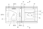
[2]欠陥検出装置の構成
図2及び図3はそれぞれ、本発明の実施形態に係る欠陥検出装置の平面図及び正面図である。欠陥検出装置は、ワークホルダ1と、撮像部2と、照明部3とを備えている。ワークホルダ1は、検査対象物を保持する機能を有している。
[2] Configuration of Defect Detection Device FIGS. 2 and 3 are a plan view and a front view, respectively, of the defect detection device according to the embodiment of the present invention. The defect detection apparatus includes a
欠陥検出装置には、撮像空間S1と作業空間S2とが設けられており、ワークホルダ1は、撮像空間S1と作業空間S2との間を往復移動することが出来る。ここで、撮像空間S1は、検査対象物の撮像が行われる空間である。又、作業空間S2は、ワークホルダ1への検査対象物のセットや検査対象物の取替え等の作業をオペレータが行う空間である。尚、図2では、欠陥検出装置が、撮像空間S1を構成する天井壁81の一部を破断して示されている。又、図3では、欠陥検出装置が、撮像空間S1を構成する前面壁82の一部を破断して示されている。
The defect detection apparatus is provided with an imaging space S1 and a work space S2, and the
具体的には、ワークホルダ1の移動経路を規定するガイドレール1Aと、ワークホルダ1を移動させる駆動部(図示せず)とが、欠陥検出装置に設けられている。又、撮像空間S1及び作業空間S2にはそれぞれ、ワークホルダ1の停止位置P1及びP2が設定されている。そして、後述する制御部7(図5参照)が駆動部を制御することにより、ワークホルダ1は、撮像空間S1内の停止位置P1と作業空間S2内の停止位置P2との間をガイドレール1Aに沿って移動する。
Specifically, a
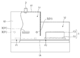
図4は、ワークホルダ1の、図2に示されるIV−IV線に沿う断面図である。ワークホルダ1は、検査テーブル11と、押え板13とから構成されている。検査テーブル11は、検査対象物が置かれる載置面11aを持ったテーブルである。本実施形態において、検査テーブル11は光透過性を有している。尚、図4には、検査対象物であるサイドエアバッグBが、載置面11a上の所定位置Ptに置かれた状態で示されている。
4 is a cross-sectional view of the
押え板13は、載置面11a上の所定位置Ptに置かれた検査対象物を、検査テーブル11へ向けて押えるために用いられる。具体的には、押え板13は、検査テーブル11の載置面11aに対して開閉自在に枢支されている。又、押え板13は、後述する撮像部2による検査対象物の撮像(画像データの取得)を妨げることがない様に、透明な材料によって形成されている。一例として、押え板13の開閉は、オペレータにより実行される。勿論、押え板13の開閉は、自動化されてもよい。
The
撮像部2は、図2及び図3に示す様に、撮像空間S1を構成する天井壁81に設置されている。具体的には、撮像部2は、撮像空間S1内の停止位置P1にワークホルダ1が停止したときに所定位置Ptと対向することとなる位置に、下向きで配されている。尚、撮像部2は、天井壁81に限らず、欠陥検出装置が設置される部屋の天井に、ワークホルダ1が撮像空間S1内の停止位置P1に停止したときに所定位置Ptと対向することとなる様に、下向きで配されてもよい。
As shown in FIGS. 2 and 3, the
撮像部2は、CCD(Charge Coupled Device)イメージセンサやCMOS(Complementary MOS)イメージセンサ等、検査対象物からの光を感知する複数の受光素子が配列されたイメージセンサを有している。そして、撮像部2は、後述する制御部7(図5参照)からの指令に基づいて、ワークホルダ1に保持された検査対象物の撮像を行うことにより(具体的には、検査対象物である縫製品の検査対象面を撮像することにより)、検査対象物の画像データを取得する。
The
照明部3は、撮像部2による検査対象物の撮像時に、検査対象物に対して光を照射する。照明部3には、反射照明部31と透過照明部(図示せず)とが含まれている。反射照明部31は、検査対象物に対して斜め上方から光の照射等を行うことにより、検査対象物での反射光を、撮像部2が持つイメージセンサに感知させる。このとき、検査対象物に対して光を直接的に照射すると、検査対象物の表面にてテカリやぎらつきが発生し、得られた画像データにおいて縫い糸等の写りが悪くなり易い。このため、反射照明部31からの光は、検査対象物に対して間接的に照射されることが好ましい。一例として、反射照明部31からの光を、撮像空間S1を構成する壁面で一旦反射させることが考えられる。透過照明部は、検査対象物に対して背後(下方)から光を照射することにより、検査対象物を通過した透過光を、撮像部2が持つイメージセンサに感知させる。そして、反射照明部31及び透過照明部は、後述する制御部7(図5参照)からの指令に基づいて、検査対象物の撮像時に選択的に点灯される。
The
本実施形態において、反射照明部31は、波長域が異なる第1照明光と第2照明光とを、検査対象物である縫製品の検査対象面に対して選択的に照射することが可能である。又、透過照明部は、検査対象物である縫製品に対して背後から透過照明光を照射する。そして、照明部3は、後述する制御部7(図5参照)からの指令に基づいて、検査対象物である縫製品の撮像時に、第1照明光、第2照明光、及び透過照明光を、縫製品に対して選択的に照射する。尚、反射照明部31は、波長域が異なる3種類以上の光を選択的に照射することが可能な構成を有していてもよい。この場合、3種類以上の光のうちの2種類の光が、適宜、第1照明光及び第2照明光としてそれぞれ用いられる。又、透過照明部は、波長域が異なる2種類以上の光を、透過照明光として選択的に照射することが可能な構成を有していてもよい。透過照明光を用いた欠陥検出技術については、後述の第3変形例にて説明される。
In the present embodiment, the
本実施形態において、第1照明光は、上糸102A(青色系の色糸)が持つ分光反射率特性において反射率が低くて且つ上糸101A(緑色系の色糸)が持つ分光反射率特性において上糸102A(青色系の色糸)よりも反射率が高い波長域Wr1を対象として、その波長域Wr1と略同一の波長域を持った光である。即ち、第1照明光には、500〜560nmの波長域に含まれた緑色系の光が用いられている。
In the present embodiment, the first illumination light has a low reflectance in the spectral reflectance characteristic of the
又、第2照明光は、上糸101A(緑色系の色糸)及び上糸102A(青色系の色糸)がそれぞれ持つ分光反射率特性の何れにおいても反射率が低い波長域Wr2を対象として、その波長域Wr2と略同一の波長域を持った光である。本実施形態では、波長域Wr2には、下糸102B(赤色系の色糸)が持つ分光反射率特性において反射率の高い波長域Wr3が重なっており、第2照明光は、その波長域が波長域Wr2と波長域Wr3とが重なった領域に含まれる様に設定されている。即ち、第2照明光には、610〜750nmの波長域に含まれた赤色系の光が用いられている。
Further, the second illumination light is intended for the wavelength region Wr2 where the reflectance is low in any of the spectral reflectance characteristics of the
図5は、欠陥検出装置の構成を概念的に示したブロック図である。図5に示す様に、欠陥検出装置は、画像処理部4と、欠陥検出部5と、記憶部6と、制御部7とを更に備えている。
FIG. 5 is a block diagram conceptually showing the structure of the defect detection apparatus. As shown in FIG. 5, the defect detection apparatus further includes an
図6は、画像処理部4の構成を概念的に示したブロック図である。図6に示す様に、画像処理部4は、変換処理部41と、前処理部42と、演算処理部43とを含んでおり、制御部7からの指令に基づいて画像処理を実行する。具体的には、画像処理部4は、撮像部2が取得した画像データ(Da1、Da2)に対して画像処理を施すことにより、縫い目101P等、欠陥検出の対象とされた部分を強調させた処理画像データ(Dp)を生成する。
FIG. 6 is a block diagram conceptually showing the configuration of the
変換処理部41は、画像データ(Da1、Da2)を構成する画素にそれぞれ含まれている画素値をグレースケールに変換することにより、変換画像データ(Db1、Db2)を生成する。前処理部42は、変換画像データに対して、明暗のムラや画像の歪み等を低減させるべく、或いはエッジを強調させるべく、シェーディング等の手法やDoG(Difference of Gaussian)フィルタ等の手段を用いて平滑化処理及び強調処理の少なくとも何れか一方を行う。これにより、演算処理部43は、2つの変換画像データ(Db1、Db2)から2つの処理画像データ(Db1’、Db2’)をそれぞれ生成する。
The
演算処理部43は、2つの処理画像データ(Db1’、Db2’)を用いて、これらの合成処理を行うことにより新たな処理画像データ(Dp)を生成する。一例として、演算処理部43は、反転処理部431と、加算処理部432とを含む。反転処理部431は、処理画像データ(Db1’、Db2’)のうちの一方の処理画像データに対して、その階調を反転させる反転処理を施すことにより、反転画像データ(Dc1)を生成する。加算処理部432は、反転画像データを、残りの処理画像データに加算することにより、縫い目101P等、欠陥検出の対象とされた部分を強調させた新たな処理画像データ(Dp)を生成する。尚、演算処理部43では、加算処理部432にて加算処理が実行される前に、反転画像データに対して、2値化処理等の強調処理やぼかし処理等が更に施されてもよい。又、加算処理の前に実行される反転処理等は、前処理部42にて実行されてもよい。
The
他の例として、演算処理部43は、2つの処理画像データ(Db1’、Db2’)を用いて減算処理を行うことにより、欠陥検出の対象とされた部分を強調させた新たな処理画像データ(Dp)を生成してもよい。この場合、演算処理部43は、反転処理部431及び加算処理部432に代えて、減算処理部を有することになる。
As another example, the
欠陥検出部5は、制御部7からの指令に基づいて欠陥検出処理を実行する。具体的には、欠陥検出部5は、画像処理部4が生成した処理画像データに基づいて、検査対象物に存在する目飛び等の欠陥を検出する。一例として、欠陥検出処理には、ブロブ解析法やエッジ検出法等の手法が用いられる。尚、欠陥検出処理には、これらの手法に限定されない様々な手法を用いることが出来る。
The
制御部7は、例えば、コンピュータに内蔵されたCPU(Central Processing Unit)である。記憶部6には、画像取得プログラムが格納されており、制御部7は、そのプログラムを記憶部6から読み出して実行することにより、ワークホルダ1、撮像部2、及び照明部3を制御する。更に、記憶部6には、画像処理プログラム及び欠陥検出プログラムが格納されており、制御部7は、これらのプログラムを記憶部6から読み出して実行することにより、画像処理部4及び欠陥検出部5をそれぞれ制御する。尚、画像取得プログラム、画像処理プログラム、及び欠陥検出プログラムは、これらを組み込んだ1つのプログラムとして構築されていてもよいし、別個のプログラムとして構築されていてもよい。
The
[3]欠陥検出装置の制御
次に、欠陥検出装置の制御部7が行う具体的な制御について、図7に示されたフローチャートに沿って説明する。
[3] Control of Defect Detection Device Next, specific control performed by the
<画像取得>
先ず、検査対象物である縫製品がワークホルダ1にセットされると、制御部7は、画像取得プログラムを記憶部6から読み出して実行し、その画像取得プログラムに基づいて、ワークホルダ1、撮像部2、及び照明部3を制御する。
<Image acquisition>
First, when a sewing product that is an inspection object is set in the
具体的には、ステップS11において、制御部7は、ワークホルダ1を、作業空間S2内の停止位置P2から撮像空間S1内の停止位置P1へ移動させる。次に、ステップS12において、制御部7は、照明部3に、縫製品に対して第1照明光を照射させ、この状態で、撮像部2に、縫製品の検査対象面を撮像させて縫製品の第1画像データDa1を取得させる。
Specifically, in step S11, the
本実施形態において、第1照明光は緑色系の光である。従って、第1照明光は、白色系のシート100、緑色系の色糸である上糸101A、及び白色系の色糸である下糸101Bにおいて、高い割合で反射される。一方、青色系の色糸である上糸102A、及び赤色系の色糸である下糸102Bでは、第1照明光は、高い割合で吸収される。よって、第1画像データDa1では、シート100、上糸101A、及び下糸101Bが、緑色系の色で写し出され、その結果、上糸101A及び下糸101Bは、それらの背景となるシート100に溶け込んだ状態となる。一方、上糸102A及び下糸102Bは、第1画像データDa1において黒色系の色(暗い色を含む)で写し出される。
In the present embodiment, the first illumination light is green light. Accordingly, the first illumination light is reflected at a high rate on the
その後、制御部7は、ワークホルダ1を停止位置P1に停止させたまま、ステップS13を実行する。ステップS13では、制御部7は、照明部3に、縫製品に対して第2照明光を照射させ、この状態で、撮像部2に、縫製品の検査対象面を撮像させて縫製品の第2画像データDa2を取得させる。尚、ステップS12及びS13は、図7に示された順序で実行されてもよいし、この順序とは逆の順序で実行されてもよい。
Thereafter, the
本実施形態において、第2照明光は赤色系の光である。従って、第2照明光は、白色系のシート100、白色系の色糸である下糸101B、及び赤色系の色糸である下糸102Bにおいて、高い割合で反射される。一方、緑色系の色糸である上糸101A、及び青色系の色糸である上糸102Aでは、第2照明光は、高い割合で吸収される。よって、第2画像データDa2では、シート100、下糸101B、及び下糸102Bが、赤色系の色で写し出され、その結果、下糸101B及び下糸102Bは、それらの背景となるシート100に溶け込んだ状態となる。一方、上糸101A及び上糸102Aは、第2画像データDa2において黒色系の色(暗い色を含む)で写し出される。
In the present embodiment, the second illumination light is red light. Accordingly, the second illumination light is reflected at a high rate on the
<画像処理>
第1画像データDa1及び第2画像データDa2が取得されると、ステップS14において、制御部7は、画像処理プログラムを記憶部6から読み出して実行し、その画像処理プログラムに基づいて、画像処理部4を制御する。具体的には、制御部7は、画像処理部4に、第1画像データDa1及び第2画像データDa2に対する画像処理を実行させることにより、処理画像データDpを生成させる。尚、画像処理プログラムの読出しは、画像取得プログラムの読出し時に行われてもよい。
<Image processing>
When the first image data Da1 and the second image data Da2 are acquired, in step S14, the
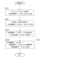
図8は、画像処理の流れを示したフローチャートである。画像処理が開始されると、ステップS21において、変換処理部41が、第1画像データDa1及び第2画像データDa2に対して変換処理を実行する。この変換処理により、第1画像データDa1及び第2画像データDa2の各々において、画素値がグレースケールに変換される。その結果、第1画像データDa1からは変換画像データDb1が生成され、第2画像データDa2からは変換画像データDb2が生成される。
FIG. 8 is a flowchart showing the flow of image processing. When image processing is started, in step S21, the
図9(a)は、画面に表示された変換画像データDb1の平面図である。第1画像データDa1では、シート100、上糸101A、及び下糸101Bが、緑色系の色で写し出されている。従って、変換画像データDb1では、シート100、上糸101A、及び下糸101Bは、明灰色系の色(白色を含む)で写し出され、その結果、上糸101A及び下糸101Bは、それらの背景となるシート100に溶け込んだ状態となる。一方、上糸102A及び下糸102Bは、変換画像データDb1において、黒色系の色で写し出される。
FIG. 9A is a plan view of the converted image data Db1 displayed on the screen. In the first image data Da1, the
図9(b)は、画面に表示された変換画像データDb2の平面図である。第2画像データDa2では、シート100、下糸101B、及び下糸102Bが、赤色系の色で写し出されている。従って、変換画像データDb2では、シート100、下糸101B、及び下糸102Bは、明灰色系の色(白色を含む)で写し出され、その結果、下糸101B及び下糸102Bは、それらの背景となるシート100に溶け込んだ状態となる。一方、上糸101A及び上糸102Aは、変換画像データDb2において、黒色系の色で写し出される。
FIG. 9B is a plan view of the converted image data Db2 displayed on the screen. In the second image data Da2, the
次に、ステップS22において、前処理部42が、変換画像データDb1及びDb2に対して平滑化処理及び強調処理の少なくとも何れか一方を実行する。この前処理により、変換画像データDb1及びDb2に生じていた明暗のムラや画像の歪み等が低減され、その結果として処理画像データDb1’及びDb2’がそれぞれ生成される。
Next, in step S22, the preprocessing
その後、ステップS23において、演算処理部43が、処理画像データDb1’及びDb2’を用いて、これらの合成処理を行うことにより処理画像データDpを新たに生成する。具体的には、ステップS231において、反転処理部431が、処理画像データDb1’に対して、その階調を反転させる反転処理を施す。これにより、図10に示された反転画像データDc1が生成される。即ち、反転画像データDc1では、シート100、上糸101A、及び下糸101Bは、黒色系の色で写し出される。一方、上糸102A及び下糸102Bは、反転画像データDc1において、白色系又は明灰色系の色で写し出される。尚、ステップS231では、反転画像データDc1に対して、2値化処理等の強調処理やぼかし処理等が更に施されてもよい。又、ステップS231は、前処理部42により実行されてもよい。
Thereafter, in step S23, the
ステップS23では次に、ステップS232において、加算処理部432が、反転画像データDc1を、処理画像データDb2’に加算することにより、処理画像データDpを新たに生成する。具体的には、処理画像データDb2’を構成する画素の画素値と、反転画像データDc1を構成する画素の画素値とを、画素の位置が互いに対応しているものどうしで加算する。これにより、処理画像データDb2’において黒色系の色で写し出されていた上糸102A(図9(b)参照)が、反転画像データDc1において白色系又は明灰色系の色で写し出された上糸102Aによって相殺される。即ち、処理画像データDb2’において黒色系の色で写し出されていた上糸102Aが、白色系又は明灰色系の色に変換される。
In step S23, in step S232, the
尚、ステップS23において、演算処理部43は、ステップS231及びS232の実行に代えて、処理画像データDb1’及びDb2’の減算処理を行うことにより、処理画像データDpを生成してもよい。具体的には、処理画像データDb1’を構成する画素の画素値と、処理画像データDb2’を構成する画素の画素値とを、画素の位置が互いに対応しているものどうしで減算する。
In step S23, the
図11は、画面に表示された処理画像データDpの平面図である。上記画像処理によれば、図11に示す様に、処理画像データDpにおいて、上糸102Aが、下糸101B及び下糸102Bと共に、それらの背景となるシート100に溶け込んだ状態となる。よって、処理画像データDpでは、上糸101Aのみが、黒色系の色(暗い色を含む)で写し出され、その結果、欠陥検出の対象とされる部分(本実施形態では縫い目101P)が強調されることになる。
FIG. 11 is a plan view of the processed image data Dp displayed on the screen. According to the image processing, as shown in FIG. 11, in the processed image data Dp, the
<欠陥検出>
処理画像データDpが生成されると、制御部7は、ステップS15(図7参照)において、欠陥検出プログラムを記憶部6から読み出して実行し、その欠陥検出プログラムに基づいて、欠陥検出部5を制御する。尚、欠陥検出プログラムの読出しは、画像取得プログラムの読出し時又は画像処理プログラムの読出し時に行われてもよい。
<Defect detection>
When the processed image data Dp is generated, the
欠陥検出処理が開始されると、欠陥検出部5は、処理画像データDpに基づいて欠陥を検出する。具体的には、欠陥検出部5は、ブロブ解析法やエッジ検出法等の手法が用いて、上糸101Aに生じた欠陥(本実施形態では、主に、縫い目101Pに存在する目飛び)を検出する。尚、欠陥検出処理には、これらの手法に限定されない様々な手法を用いることが出来る。
When the defect detection process is started, the
本実施形態の欠陥検出装置によれば、縫製品において縫い糸として用いられた色糸が持つ分光反射率特性が巧みに利用され、その結果として、画像処理において、欠陥検出の対象とされる部分の抽出が実現されている。よって、本実施形態の欠陥検出装置は、縫合線101と縫合線102との交差箇所であっても、上糸101Aに生じた欠陥を高い精度で検出することが可能である。
According to the defect detection device of the present embodiment, the spectral reflectance characteristics of the colored yarn used as the sewing thread in the sewing product are skillfully used, and as a result, in the image processing, the portion that is the target of defect detection Extraction is realized. Therefore, the defect detection apparatus of the present embodiment can detect a defect generated in the
本実施形態において、第1画像データDa1では、上糸101A(緑色系の色糸)を、その背景となるシート100に溶け込ませ、第2画像データDa2では、上糸101Aを、その背景となるシート100に溶け込ませずに黒色系の色(暗い色を含む)で写し出すという点が重要である。この様な第1画像データDa1及び第2画像データDa2の取得には、色糸が持つ分光反射率特性を考慮して、適切な波長域の光を第1照明光及び第2照明光として選択することが重要であることに加えて、背景となるシート100の色として白色系の色を選択することが重要である。
In the present embodiment, in the first image data Da1, the
[4]変形例
[4−1]第1変形例
上記欠陥検出装置を応用することにより、縫製品において縫い糸として用いられている2種類の色糸を別個に抽出し、各色糸について欠陥を検出することが可能となる。一例として、上糸102Aが黒色系の色糸であり、且つ下糸102Bが赤色系の色糸である縫製品において、上糸102Aと下糸102Bとを別個に抽出し、各色糸について欠陥を検出する場合について説明する。
[4] Modification [4-1] First Modification By applying the defect detection device, two types of color yarns used as sewing threads in the sewn product are extracted separately, and defects are detected for each color thread. It becomes possible to do. As an example, in a sewing product in which the
本変形例の欠陥検出装置では、第1照明光として、610〜750nmの波長域に含まれた赤色系の光が用いられ、第2照明光として、500〜560nmの波長域に含まれた緑色系の光が用いられる。 In the defect detection device of this modification, red light included in the wavelength range of 610 to 750 nm is used as the first illumination light, and green light included in the wavelength range of 500 to 560 nm is used as the second illumination light. System light is used.
第1照明光は、白色系のシート100、及び赤色系の色糸である下糸102Bにおいて、高い割合で反射される。一方、黒色系の色糸である上糸102Aでは、第1照明光は、高い割合で吸収される。従って、ステップS12で得られる第1画像データDa1では、シート100及び下糸102Bが、赤色系の色で写し出され、その結果、下糸102Bは、その背景となるシート100に溶け込んだ状態となる。一方、上糸102Aは、第1画像データDa1において黒色系の色(暗い色を含む)で写し出される。
The first illumination light is reflected at a high rate on the
又、第1画像データDa1から生成された変換画像データDb1では、シート100及び下糸102Bは、明灰色系の色(白色を含む)で写し出され、その結果、下糸102Bは、その背景となるシート100に溶け込んだ状態となる。一方、上糸102Aは、変換画像データDb1において、黒色系の色で写し出される。従って、変換画像データDb1では、上糸102A及び下糸102Bのうちの上糸102Aのみが、黒色系の色で写し出される。即ち、上糸102Aが抽出される。よって、変換画像データDb1、又はこれに平滑化処理等を施して得られる処理画像データDb1’を用いて欠陥検出処理が実行されることにより、上糸102Aに生じた欠陥が高い精度で検出されることになる。
Further, in the converted image data Db1 generated from the first image data Da1, the
第2照明光は、白色系のシート100において高い割合で反射される。一方、黒色系の色糸である上糸102A、及び赤色系の色糸である下糸102Bでは、第2照明光は、高い割合で吸収される。よって、ステップS13で得られる第2画像データDa2では、シート100が緑色系の色で写し出される一方で、上糸102A及び下糸102Bが黒色系の色(暗い色を含む)で写し出される。
The second illumination light is reflected at a high rate in the
よって、第1画像データDa1及び第2画像データDa2に対して、上記実施形態と同じ画像処理(図8参照)が施されることにより、生成される処理画像データDpにおいて、上糸102A及び下糸102Bのうちの下糸102Bのみが、黒色系の色で写し出されることになる。即ち、下糸102Bが、上糸102Aとは別個に抽出される。よって、処理画像データDpを用いて欠陥検出処理が実行されることにより、下糸102Bに生じた欠陥が高い精度で検出されることになる。
Therefore, the first image data Da1 and the second image data Da2 are subjected to the same image processing (see FIG. 8) as in the above-described embodiment, so that the
本変形例の欠陥検出装置によれば、2種類の色糸が別個に抽出され、各色糸について欠陥が検出される。よって、欠陥が検出された場合に、その欠陥を生じた色糸が特定されることになる。 According to the defect detection apparatus of this modification, two types of color yarns are extracted separately, and defects are detected for each color yarn. Therefore, when a defect is detected, the color yarn that causes the defect is specified.
他の例として、縫製品において黄色系の色糸と緑色系の色糸とが縫い糸として用いられている場合、第1照明光として、610〜750nmの波長域に含まれた赤色系の光を用い、第2照明光として、435〜480nmの波長域に含まれた青色系の光を用いることにより、2種類の色糸を別個に抽出することが出来る。 As another example, when a yellow color thread and a green color thread are used as a sewing thread in a sewing product, red light included in a wavelength region of 610 to 750 nm is used as the first illumination light. By using blue light contained in the wavelength region of 435 to 480 nm as the second illumination light, two types of color yarns can be extracted separately.
更なる他の例として、縫製品において青色系の色糸と緑色系の色糸とが縫い糸として用いられている場合、第1照明光として、435〜480nmの波長域に含まれた青色系の光を用い、第2照明光として、610〜750nmの波長域に含まれた赤色系の光を用いることにより、2種類の色糸を別個に抽出することが出来る。 As yet another example, when a blue color thread and a green color thread are used as a sewing thread in a sewn product, the blue light included in the wavelength region of 435 to 480 nm is used as the first illumination light. By using light and using red light included in the wavelength region of 610 to 750 nm as the second illumination light, two types of color yarns can be extracted separately.
[4−2]第2変形例
上記欠陥検出装置を応用することにより、縫製品の基材として黒色系のものが用いられている場合にも、色の異なる2種類の縫い糸(第1及び第2の色糸)に生じた欠陥を検出することが出来る。この場合、第2照明光として、第1及び第2の色糸がそれぞれ持つ分光反射率特性の何れにおいても反射率が高い波長域を対象として、その波長域と略同一の波長域を持った光が用いられる。尚、第1照明光は、上記実施形態と同様、第1の色糸が持つ分光反射率特性において反射率が低くて且つ第2の色糸が持つ分光反射率特性において第1の色糸よりも反射率が高い波長域を対象として、その波長域と略同一の波長域を持った光である。
[4-2] Second Modification By applying the defect detection device, two types of sewing threads having different colors (first and first) can be used even when a black base material is used as the base material of the sewing product. 2), it is possible to detect a defect occurring in the second colored yarn). In this case, the second illumination light has a wavelength region that is substantially the same as the wavelength region with a high reflectance in any of the spectral reflectance characteristics of the first and second color yarns. Light is used. The first illumination light has a lower reflectance in the spectral reflectance characteristic of the first color thread and the spectral reflectance characteristics of the second color thread than the first color thread, as in the above embodiment. In addition, the light having a wavelength region that is substantially the same as the wavelength region is targeted for the wavelength region having a high reflectance.
本変形例では、次の点が重要である。即ち、第1画像データDa1において、第1の色糸を、その背景となる基材(黒色系の色)に溶け込ませる一方で、第2の色糸を、第1照明光と同色の色で写し出す。又、第2画像データDa2において、第1の色糸を、その背景となる基材(黒色系の色)に溶け込ませずに第2照明光と同色の色で写し出し、これと共に、第2の色糸も、第2照明光と同色の色で写し出す。この様な第1画像データDa1及び第2画像データDa2を用いることにより、縫製品の基材が黒色系であっても、第1及び第2の色糸を別個に抽出し、各色糸について欠陥を検出することが可能となる。 In the present modification, the following points are important. That is, in the first image data Da1, the first color yarn is mixed with the base material (black color) as the background, while the second color yarn is the same color as the first illumination light. Copy. Further, in the second image data Da2, the first colored yarn is copied in the same color as the second illumination light without being melted into the base material (black color) as the background. The colored yarn is also projected in the same color as the second illumination light. By using the first image data Da1 and the second image data Da2 as described above, even if the base material of the sewing product is black, the first and second color yarns are extracted separately, and defects for each color yarn are detected. Can be detected.
[4−3]第3変形例
上記欠陥検出装置において、縫い糸として用いられた色糸が持つ分光反射率特性に限らず、それらの色糸が持つ分光透過率特性が、縫い糸に生じた欠陥の検出に利用されてもよい。この場合、上述した実施形態及び変形例において「反射率」が「透過率」に読み替えられる。又、照明部3の透過照明部が、第1照明光と第2照明光とを、検査対象物である縫製品の検査対象面に対して縫製品の背後から選択的に照射することになる。本変形例によれば、分光反射率特性を利用した場合と同様、第1及び第2の色糸を別個に抽出し、各色糸について欠陥を検出することが出来る。
[4-3] Third Modification In the defect detection device described above, not only the spectral reflectance characteristics of the colored yarn used as the sewing thread, but also the spectral transmittance characteristics of the colored threads are the defects of the sewing thread. It may be used for detection. In this case, “reflectance” is read as “transmittance” in the embodiment and the modification described above. Further, the transmission illumination unit of the
尚、本発明の各部構成は上記実施形態に限らず、特許請求の範囲に記載の技術的範囲内で種々の変形が可能である。例えば、上記欠陥検出装置は、第1照明光及び第2照明光を適宜選択することにより、様々な色糸が縫い糸として用いられている縫製品の検査に適用することが出来る。 In addition, each part structure of this invention is not restricted to the said embodiment, A various deformation | transformation is possible within the technical scope as described in a claim. For example, the defect detection device can be applied to inspection of a sewing product in which various colored yarns are used as sewing threads by appropriately selecting the first illumination light and the second illumination light.
又、照明部3は、435〜480nmの波長域に含まれた青色系の光、500〜560nmの波長域に含まれた緑色系の光、及び610〜750nmの波長域に含まれた赤色系の光を、縫製品に対して選択的に照射することが可能な構成を有していてもよい。この場合、3種類の光のうちの2種類の光が、適宜、第1照明光及び第2照明光としてそれぞれ用いられる。又、これらの3種類の光に限らず、様々な波長域の光が第1照明光又は第2照明光として用いられてもよい。例えば、380nmより小さい波長域に含まれる紫外線や、780nmより大きい波長域に含まれる赤外線が用いられてもよい。
The
本発明に係る欠陥検出装置は、エアバッグの検査に限らず、色糸が縫い糸として用いられている様々な縫製品の検査に適用することが出来る。 The defect detection apparatus according to the present invention can be applied not only to the inspection of airbags but also to the inspection of various sewing products in which colored yarns are used as sewing threads.
1 ワークホルダ
1A ガイドレール
11 検査テーブル
11a 載置面
13 押え板
2 撮像部
3 照明部
4 画像処理部
41 変換処理部
42 前処理部
43 演算処理部
431 反転処理部
432 加算処理部
5 欠陥検出部
6 記憶部
7 制御部
81 天井壁
82 前面壁
100 シート
100a 外周縁
101、102 縫合線
101A、102A 上糸
101B、102B 下糸
101P、102P 縫い目
B サイドエアバッグ
S1 撮像空間
S2 作業空間
Pt 所定位置
P1、P2 停止位置
Da1 第1画像データ
Da2 第2画像データ
Db1、Db2 変換画像データ
Db1’、Db2’ 処理画像データ
Dc1 反転画像データ
Dp 処理画像データ
Wr1、Wr2、Wr3 波長域
S11、S12、S13、S14、S15 ステップ
S21、S22、S23、S231、S232 ステップ
DESCRIPTION OF
Claims (7)
前記第1の色糸が持つ分光反射率特性において反射率が低くて且つ前記第2の色糸が持つ分光反射率特性において前記第1の色糸よりも反射率が高い波長域と略同一の波長域を持った第1照明光を、前記縫製品の検査対象面に対して照射する照明部と、
前記縫製品の前記検査対象面を撮像する撮像部と
を備え、
前記照明部に、前記縫製品に対して前記第1照明光を照射させ、この状態で、前記撮像部に、前記縫製品の前記検査対象面を撮像させて前記縫製品の第1画像データを取得させ、
前記撮像部に取得させた前記第1画像データ、又は前記第1画像データに画像処理を施すことにより生成された処理画像データに基づいて、前記欠陥を検出する、欠陥検出装置。 In a sewing product in which a first colored yarn and a second colored yarn having a different color from the first colored yarn are used as a sewing yarn, the defect detecting device detects a defect generated in the sewing yarn. And
In the spectral reflectance characteristic of the first color yarn, the reflectance is low, and in the spectral reflectance characteristic of the second color yarn, the wavelength region is substantially the same as the wavelength region where the reflectance is higher than that of the first color yarn. An illumination unit that irradiates the surface to be inspected of the sewing product with first illumination light having a wavelength range;
An imaging unit that images the inspection target surface of the sewing product,
The illumination unit is configured to irradiate the sewing product with the first illumination light, and in this state, the imaging unit causes the inspection target surface of the sewing product to be imaged to obtain first image data of the sewing product. Let's get
A defect detection apparatus that detects the defect based on the first image data acquired by the imaging unit or processed image data generated by performing image processing on the first image data.
前記照明部は、前記第1及び前記第2の色糸がそれぞれ持つ分光反射率特性の何れにおいても反射率が低い波長域、又は前記第1及び前記第2の色糸がそれぞれ持つ分光反射率特性の何れにおいても反射率が高い波長域の何れかと略同一の波長域を持った第2照明光と、前記第1照明光とを、前記縫製品の前記検査対象面に対して選択的に照射することが可能である、請求項1に記載の欠陥検出装置であって、
前記制御部は、
(i)前記照明部に、前記縫製品に対して前記第1照明光を照射させ、この状態で、前記撮像部に、前記縫製品の前記検査対象面を撮像させて前記縫製品の第1画像データを取得させる制御と、
(ii)前記照明部に、前記縫製品に対して前記第2照明光を照射させ、この状態で、前記撮像部に、前記縫製品の前記検査対象面を撮像させて前記縫製品の第2画像データを取得させる制御と、
(iii)前記画像処理部に、前記第1画像データ及び前記第2画像データに対する画像処理を実行させることにより、処理画像データを生成させる制御と、
(iv)前記欠陥検出部に、前記処理画像データに基づいて前記欠陥を検出させる制御と
を行い、
前記制御(iii)では、前記画像処理部は、前記制御(i)で得られた前記第1画像データと、前記制御(ii)で得られた前記第2画像データとを用いることにより、前記第1及び前記第2の色糸のうちの何れか一方の色糸のみが抽出された画像データを、前記処理画像データとして生成する、欠陥検出装置。 An image processing unit, a defect detection unit, and a control unit;
The illumination unit has a wavelength range in which the reflectance is low in any of the spectral reflectance characteristics of the first and second color yarns, or the spectral reflectance of the first and second color yarns, respectively. The second illumination light having substantially the same wavelength region as any of the wavelength regions having high reflectance in any of the characteristics, and the first illumination light are selectively selected with respect to the inspection target surface of the sewing product. The defect detection apparatus according to claim 1, wherein the defect detection apparatus is capable of irradiation.
The controller is
(I) The illumination unit is configured to irradiate the sewing product with the first illumination light, and in this state, the imaging unit is caused to image the inspection target surface of the sewing product and the first sewing product Control to acquire image data;
(Ii) The illumination unit is configured to irradiate the sewing product with the second illumination light, and in this state, the imaging unit is caused to image the inspection target surface of the sewing product, so that the second of the sewing product is obtained. Control to acquire image data;
(Iii) control for generating processed image data by causing the image processing unit to perform image processing on the first image data and the second image data;
(Iv) performing control to cause the defect detection unit to detect the defect based on the processed image data;
In the control (iii), the image processing unit uses the first image data obtained in the control (i) and the second image data obtained in the control (ii). A defect detection apparatus that generates, as the processed image data, image data in which only one of the first and second color yarns is extracted.
前記第1の色糸が持つ分光透過率特性において透過率が低くて且つ前記第2の色糸が持つ分光透過率特性において前記第1の色糸よりも透過率が高い波長域と略同一の波長域を持った第1照明光を、前記縫製品の検査対象面に対して前記縫製品の背後から照射する照明部と、
前記縫製品の前記検査対象面を撮像する撮像部と
を備え、
前記照明部に、前記縫製品に対して前記第1照明光を照射させ、この状態で、前記撮像部に、前記縫製品の前記検査対象面を撮像させて前記縫製品の第1画像データを取得させ、
前記撮像部に取得させた前記第1画像データ、又は前記第1画像データに画像処理を施すことにより生成された処理画像データに基づいて、前記欠陥を検出する、欠陥検出装置。 In a sewing product in which a first colored yarn and a second colored yarn having a different color from the first colored yarn are used as a sewing yarn, the defect detecting device detects a defect generated in the sewing yarn. And
The spectral transmittance characteristic of the first color yarn has a low transmittance, and the spectral transmittance characteristic of the second color yarn has substantially the same wavelength range as the transmittance higher than that of the first color yarn. An illumination unit that irradiates a first illumination light having a wavelength range from behind the sewing product to a surface to be inspected of the sewing product;
An imaging unit that images the inspection target surface of the sewing product,
The illumination unit is configured to irradiate the sewing product with the first illumination light, and in this state, the imaging unit causes the inspection target surface of the sewing product to be imaged to obtain first image data of the sewing product. Let's get
A defect detection apparatus that detects the defect based on the first image data acquired by the imaging unit or processed image data generated by performing image processing on the first image data.
前記照明部は、前記第1及び前記第2の色糸がそれぞれ持つ分光透過率特性の何れにおいても透過率が低い波長域、又は前記第1及び前記第2の色糸がそれぞれ持つ分光透過率特性の何れにおいても透過率が高い波長域の何れかと略同一の波長域を持った第2照明光と、前記第1照明光とを、前記縫製品の前記検査対象面に対して前記縫製品の背後から選択的に照射することが可能である、請求項3に記載の欠陥検出装置であって、
前記制御部は、
(i)前記照明部に、前記縫製品に対して前記第1照明光を照射させ、この状態で、前記撮像部に、前記縫製品の前記検査対象面を撮像させて前記縫製品の第1画像データを取得させる制御と、
(ii)前記照明部に、前記縫製品に対して前記第2照明光を照射させ、この状態で、前記撮像部に、前記縫製品の前記検査対象面を撮像させて前記縫製品の第2画像データを取得させる制御と、
(iii)前記画像処理部に、前記第1画像データ及び前記第2画像データに対する画像処理を実行させることにより、処理画像データを生成させる制御と、
(iv)前記欠陥検出部に、前記処理画像データに基づいて前記欠陥を検出させる制御と
を行い、
前記制御(iii)では、前記画像処理部は、前記制御(i)で得られた前記第1画像データと、前記制御(ii)で得られた前記第2画像データとを用いることにより、前記第1及び前記第2の色糸のうちの何れか一方の色糸のみが抽出された画像データを、前記処理画像データとして生成する、欠陥検出装置。 An image processing unit, a defect detection unit, and a control unit;
The illumination unit has a wavelength range in which the transmittance is low in any of the spectral transmittance characteristics of the first and second color yarns, or the spectral transmittance of the first and second color yarns, respectively. In any of the characteristics, the second illumination light having substantially the same wavelength range as any one of the wavelength ranges having high transmittance and the first illumination light are applied to the sewing product with respect to the inspection target surface of the sewing product. It is possible to selectively irradiate from behind the defect detection device according to claim 3,
The controller is
(I) The illumination unit is configured to irradiate the sewing product with the first illumination light, and in this state, the imaging unit is caused to image the inspection target surface of the sewing product and the first sewing product Control to acquire image data;
(Ii) The illumination unit is configured to irradiate the sewing product with the second illumination light, and in this state, the imaging unit is caused to image the inspection target surface of the sewing product, so that the second of the sewing product is obtained. Control to acquire image data;
(Iii) control for generating processed image data by causing the image processing unit to perform image processing on the first image data and the second image data;
(Iv) performing control to cause the defect detection unit to detect the defect based on the processed image data;
In the control (iii), the image processing unit uses the first image data obtained in the control (i) and the second image data obtained in the control (ii). A defect detection apparatus that generates, as the processed image data, image data in which only one of the first and second color yarns is extracted.
(A)前記第1画像データ及び前記第2画像データについて、それらに含まれる画素値をグレースケールに変換することにより、2つの変換画像データを生成する処理と、
(B)前記処理(A)により生成された前記2つの変換画像データを用いて、これらの合成処理を行うことにより前記処理画像データを生成する処理と
を行う、請求項2又は4に記載の欠陥検出装置。 In the control (iii), the image processing unit
(A) A process of generating two pieces of converted image data by converting pixel values included in the first image data and the second image data into grayscale,
(B) Using the two converted image data generated by the process (A), a process of generating the processed image data by performing a synthesis process thereof is performed. Defect detection device.
前記第1の色糸が持つ分光反射率特性において反射率が低くて且つ前記第2の色糸が持つ分光反射率特性において前記第1の色糸よりも反射率が高い波長域と略同一の波長域を持った第1照明光を、前記縫製品の検査対象面に対して照射し、この状態で、前記縫製品の前記検査対象面を撮像して前記縫製品の第1画像データを取得するステップと、
取得した前記第1画像データ、又は前記第1画像データに画像処理を施すことにより生成された処理画像データに基づいて、前記欠陥を検出するステップと
を有する、欠陥検出方法。 This is a defect detection method for detecting defects generated in a sewing thread in a sewing product in which a first color thread and a second color thread having a different color from the first color thread are used as a sewing thread. And
In the spectral reflectance characteristic of the first color yarn, the reflectance is low, and in the spectral reflectance characteristic of the second color yarn, the wavelength region is substantially the same as the wavelength region where the reflectance is higher than that of the first color yarn. First illumination light having a wavelength range is irradiated onto the inspection target surface of the sewing product, and in this state, the inspection target surface of the sewing product is imaged to obtain first image data of the sewing product. And steps to
And a step of detecting the defect based on the acquired first image data or processed image data generated by performing image processing on the first image data.
前記第1の色糸が持つ分光透過率特性において透過率が低くて且つ前記第2の色糸が持つ分光透過率特性において前記第1の色糸よりも透過率が高い波長域と略同一の波長域を持った第1照明光を、前記縫製品の検査対象面に対して前記縫製品の背後から照射し、この状態で、前記縫製品の前記検査対象面を撮像して前記縫製品の第1画像データを取得するステップと、
取得した前記第1画像データ、又は前記第1画像データに画像処理を施すことにより生成された処理画像データに基づいて、前記欠陥を検出するステップと
を有する、欠陥検出方法。 This is a defect detection method for detecting defects generated in a sewing thread in a sewing product in which a first color thread and a second color thread having a different color from the first color thread are used as a sewing thread. And
The spectral transmittance characteristic of the first color yarn has a low transmittance, and the spectral transmittance characteristic of the second color yarn has substantially the same wavelength range as the transmittance higher than that of the first color yarn. A first illumination light having a wavelength range is irradiated from behind the sewing product onto the surface to be inspected of the sewing product, and in this state, the surface to be inspected of the sewing product is imaged. Obtaining first image data;
And a step of detecting the defect based on the acquired first image data or processed image data generated by performing image processing on the first image data.
Priority Applications (3)
| Application Number | Priority Date | Filing Date | Title |
|---|---|---|---|
| JP2014069358A JP6220714B2 (en) | 2014-03-28 | 2014-03-28 | Defect detection apparatus and defect detection method |
| CN201580017050.3A CN106461567B (en) | 2014-03-28 | 2015-03-17 | Defect detecting device and defect inspection method |
| PCT/JP2015/001457 WO2015146063A1 (en) | 2014-03-28 | 2015-03-17 | Defect detecting apparatus and defect detecting method |
Applications Claiming Priority (1)
| Application Number | Priority Date | Filing Date | Title |
|---|---|---|---|
| JP2014069358A JP6220714B2 (en) | 2014-03-28 | 2014-03-28 | Defect detection apparatus and defect detection method |
Publications (2)
| Publication Number | Publication Date |
|---|---|
| JP2015190898A true JP2015190898A (en) | 2015-11-02 |
| JP6220714B2 JP6220714B2 (en) | 2017-10-25 |
Family
ID=54194614
Family Applications (1)
| Application Number | Title | Priority Date | Filing Date |
|---|---|---|---|
| JP2014069358A Active JP6220714B2 (en) | 2014-03-28 | 2014-03-28 | Defect detection apparatus and defect detection method |
Country Status (3)
| Country | Link |
|---|---|
| JP (1) | JP6220714B2 (en) |
| CN (1) | CN106461567B (en) |
| WO (1) | WO2015146063A1 (en) |
Cited By (4)
| Publication number | Priority date | Publication date | Assignee | Title |
|---|---|---|---|---|
| KR20180067205A (en) * | 2016-12-12 | 2018-06-20 | 엘림광통신 주식회사 | A computer-readable recording medium with needle error detection program for weaving loom |
| KR20180067219A (en) * | 2016-12-12 | 2018-06-20 | 엘림광통신 주식회사 | A needle error detection appratus for weaving loom |
| WO2021250736A1 (en) * | 2020-06-08 | 2021-12-16 | 日本電気株式会社 | Air bag inspection device, air bag inspection system, air bag inspection method, and recording medium |
| WO2022137748A1 (en) * | 2020-12-23 | 2022-06-30 | 株式会社前川製作所 | Object detection device, machine learning implementation device, object detection program, and machine learning implementation program |
Citations (5)
| Publication number | Priority date | Publication date | Assignee | Title |
|---|---|---|---|---|
| JPS6312756A (en) * | 1986-06-28 | 1988-01-20 | 日産自動車株式会社 | Weaving falw detector |
| JPH10512331A (en) * | 1995-01-12 | 1998-11-24 | モナーク・ニッティング・マシーナリー・コーポレーション | Sock inspection and grading device and sock inspection method |
| JPH1190077A (en) * | 1997-09-16 | 1999-04-06 | Toyota Central Res & Dev Lab Inc | Stitch checking device |
| JP2012112688A (en) * | 2010-11-22 | 2012-06-14 | Seiko Epson Corp | Inspection apparatus |
| JP2013148554A (en) * | 2012-01-23 | 2013-08-01 | Toyota Motor Corp | Electrode substrate inspection method |
Family Cites Families (7)
| Publication number | Priority date | Publication date | Assignee | Title |
|---|---|---|---|---|
| DE3707321C1 (en) * | 1987-03-07 | 1988-06-16 | Pfaff Ind Masch | Sewing machine with a thread monitor for the thread of the bobbin |
| JPH0292391A (en) * | 1988-09-29 | 1990-04-03 | Aisin Seiki Co Ltd | Cloth end detector of sewing machine |
| JPH0716376A (en) * | 1993-06-30 | 1995-01-20 | Mitsubishi Rayon Co Ltd | Skip stitch inspecting device |
| JP3576083B2 (en) * | 2000-09-06 | 2004-10-13 | ペガサスミシン製造株式会社 | Sewing defect detection device |
| JP2006262978A (en) * | 2005-03-22 | 2006-10-05 | Matsuya R & D:Kk | Stitch skipping and empty sewing detection device for lock-stitch sewing machine |
| JP2008237315A (en) * | 2007-03-26 | 2008-10-09 | Juki Corp | Sewing machine |
| JP5064539B2 (en) * | 2009-11-13 | 2012-10-31 | 木下精密工業株式会社 | Stitch skipping check device for sewing device |
-
2014
- 2014-03-28 JP JP2014069358A patent/JP6220714B2/en active Active
-
2015
- 2015-03-17 CN CN201580017050.3A patent/CN106461567B/en active Active
- 2015-03-17 WO PCT/JP2015/001457 patent/WO2015146063A1/en active Application Filing
Patent Citations (5)
| Publication number | Priority date | Publication date | Assignee | Title |
|---|---|---|---|---|
| JPS6312756A (en) * | 1986-06-28 | 1988-01-20 | 日産自動車株式会社 | Weaving falw detector |
| JPH10512331A (en) * | 1995-01-12 | 1998-11-24 | モナーク・ニッティング・マシーナリー・コーポレーション | Sock inspection and grading device and sock inspection method |
| JPH1190077A (en) * | 1997-09-16 | 1999-04-06 | Toyota Central Res & Dev Lab Inc | Stitch checking device |
| JP2012112688A (en) * | 2010-11-22 | 2012-06-14 | Seiko Epson Corp | Inspection apparatus |
| JP2013148554A (en) * | 2012-01-23 | 2013-08-01 | Toyota Motor Corp | Electrode substrate inspection method |
Cited By (6)
| Publication number | Priority date | Publication date | Assignee | Title |
|---|---|---|---|---|
| KR20180067205A (en) * | 2016-12-12 | 2018-06-20 | 엘림광통신 주식회사 | A computer-readable recording medium with needle error detection program for weaving loom |
| KR20180067219A (en) * | 2016-12-12 | 2018-06-20 | 엘림광통신 주식회사 | A needle error detection appratus for weaving loom |
| KR101968250B1 (en) | 2016-12-12 | 2019-04-11 | 주식회사 세파테크놀로지 | A computer-readable recording medium with needle error detection program for weaving loom |
| KR101968252B1 (en) | 2016-12-12 | 2019-08-13 | 주식회사 세파테크놀로지 | A needle error detection appratus for weaving loom |
| WO2021250736A1 (en) * | 2020-06-08 | 2021-12-16 | 日本電気株式会社 | Air bag inspection device, air bag inspection system, air bag inspection method, and recording medium |
| WO2022137748A1 (en) * | 2020-12-23 | 2022-06-30 | 株式会社前川製作所 | Object detection device, machine learning implementation device, object detection program, and machine learning implementation program |
Also Published As
| Publication number | Publication date |
|---|---|
| CN106461567A (en) | 2017-02-22 |
| JP6220714B2 (en) | 2017-10-25 |
| CN106461567B (en) | 2019-07-23 |
| WO2015146063A1 (en) | 2015-10-01 |
Similar Documents
| Publication | Publication Date | Title |
|---|---|---|
| JP6917781B2 (en) | Image inspection equipment | |
| JP6220714B2 (en) | Defect detection apparatus and defect detection method | |
| JP4826750B2 (en) | Defect inspection method and defect inspection apparatus using the method | |
| JP4060750B2 (en) | Imaging inspection system | |
| JP6967373B2 (en) | Image inspection equipment | |
| JP2020187657A (en) | Image inspection device | |
| JP7188870B2 (en) | Image inspection equipment | |
| KR101721965B1 (en) | Device and method for inspecting appearance of transparent substrate | |
| JP2009097922A (en) | Visual inspection method and apparatus | |
| WO2011086634A1 (en) | Liquid crystal panel inspection method and device | |
| JP2017040510A (en) | Inspection apparatus, inspection method, and object manufacturing method | |
| JP6917780B2 (en) | Image inspection equipment | |
| JPWO2020071162A1 (en) | Teacher data generator, inspection device and computer program | |
| JP2007278915A (en) | Device and method for inspecting defect of tool | |
| JP2012242148A (en) | Appearance inspection apparatus and appearance inspection method of transparent bottle | |
| US20230342909A1 (en) | System and method for imaging reflecting objects | |
| JP5773741B2 (en) | Appearance inspection apparatus and appearance inspection method for transparent body bottle | |
| JP2006313147A (en) | Defect inspection method, and defect inspection device using same | |
| JP4184511B2 (en) | Method and apparatus for defect inspection of metal sample surface | |
| JP2018205000A (en) | Image inspection device | |
| JP2018204995A (en) | Image inspection device | |
| JP2018205001A (en) | Image inspection device | |
| JP2023137057A (en) | Method of generating defect prediction model, bottle appearance inspection method and bottle appearance inspection device | |
| JP2013210227A (en) | Visual inspection device for light transmitting molding | |
| JP2013108879A (en) | Defect inspection method for periodic pattern and defect inspection device for periodic pattern |
Legal Events
| Date | Code | Title | Description |
|---|---|---|---|
| A621 | Written request for application examination |
Free format text: JAPANESE INTERMEDIATE CODE: A621 Effective date: 20170323 |
|
| TRDD | Decision of grant or rejection written | ||
| A01 | Written decision to grant a patent or to grant a registration (utility model) |
Free format text: JAPANESE INTERMEDIATE CODE: A01 Effective date: 20170905 |
|
| A61 | First payment of annual fees (during grant procedure) |
Free format text: JAPANESE INTERMEDIATE CODE: A61 Effective date: 20171002 |
|
| R150 | Certificate of patent or registration of utility model |
Ref document number: 6220714 Country of ref document: JP Free format text: JAPANESE INTERMEDIATE CODE: R150 |
|
| R250 | Receipt of annual fees |
Free format text: JAPANESE INTERMEDIATE CODE: R250 |
|
| R250 | Receipt of annual fees |
Free format text: JAPANESE INTERMEDIATE CODE: R250 |