JP2015174193A - Loader device and machine tool - Google Patents

Loader device and machine tool Download PDF

Info

Publication number
JP2015174193A
JP2015174193A JP2014053216A JP2014053216A JP2015174193A JP 2015174193 A JP2015174193 A JP 2015174193A JP 2014053216 A JP2014053216 A JP 2014053216A JP 2014053216 A JP2014053216 A JP 2014053216A JP 2015174193 A JP2015174193 A JP 2015174193A
Authority
JP
Japan
Prior art keywords
moving body
guide member
loader device
workpiece
bending range
Prior art date
Legal status (The legal status is an assumption and is not a legal conclusion. Google has not performed a legal analysis and makes no representation as to the accuracy of the status listed.)
Pending
Application number
JP2014053216A
Other languages
Japanese (ja)
Inventor
章雄 中島
Akio Nakajima
章雄 中島
Current Assignee (The listed assignees may be inaccurate. Google has not performed a legal analysis and makes no representation or warranty as to the accuracy of the list.)
Murata Machinery Ltd
Original Assignee
Murata Machinery Ltd
Priority date (The priority date is an assumption and is not a legal conclusion. Google has not performed a legal analysis and makes no representation as to the accuracy of the date listed.)
Filing date
Publication date
Application filed by Murata Machinery Ltd filed Critical Murata Machinery Ltd
Priority to JP2014053216A priority Critical patent/JP2015174193A/en
Publication of JP2015174193A publication Critical patent/JP2015174193A/en
Pending legal-status Critical Current

Links

Images

Abstract

PROBLEM TO BE SOLVED: To provide a loader device and a machine tool capable of reducing noise of a protective guide member.SOLUTION: A loader device 100 comprises: a Y moving body 23b moving in at least a first direction D1 and a second direction D2 crossing the first direction D1 with respect to an X moving body 21b; and a third protective guide member 33 connecting the Y moving body 23b to the X moving body 21b and also storing cables, and conveys a work-piece W by the movement of the Y moving body 23b. The third protective guide member 33 is formed by connecting a plurality of link members 34 arranged in bending areas 33a and 33c of the total length and connected so as to be bendable, to a connection member 35 arranged in a non-bending area 33b except for the bending areas 33a and 33c and longer in the longitudinal direction than one link member 34.

Description

本発明は、ローダ装置及び工作機械に関する。   The present invention relates to a loader device and a machine tool.

旋盤などの工作機械として、加工対象のワークを保持する主軸と、ワーク搬入部との間においてワークを搬送するローダ装置を備えた構成が知られている。ローダ装置は、移動体と、この移動体と所定の固定部とを接続しかつケーブル類を収容する保護案内部材とを備えており、移動体の移動によってワークを搬送する構成となっている。移動体には、例えばワークを保持するチャック等が取り付けられる。保護案内部材は、例えばチャックを駆動する電源供給用のケーブルなどのケーブル類を収容することで、これらのケーブル類が絡まるのを防止している。   As a machine tool such as a lathe, a configuration including a loader device that conveys a workpiece between a spindle that holds a workpiece to be machined and a workpiece carry-in unit is known. The loader device includes a moving body and a protective guide member that connects the moving body and a predetermined fixed portion and accommodates cables, and is configured to convey a workpiece by the movement of the moving body. For example, a chuck or the like that holds a workpiece is attached to the movable body. The protective guide member accommodates cables such as a power supply cable for driving the chuck, for example, thereby preventing the cables from being tangled.

保護案内部材は、例えば所定の固定部と移動体とを接続して設けられ、長手方向に複数のリンク部材が連結されて形成されている(例えば、特許文献1参照)。各種ケーブル類は、例えば複数のリンク部材を連結方向に貫通するように収容される。この構成により、移動体が移動すると、その移動による力が1つ1つのリンク部材に順に伝達されてリンク部材同士の間が屈曲する。このため、保護案内部材全体は移動体の移動に対して追従するように変形する。   The protection guide member is provided, for example, by connecting a predetermined fixed portion and a moving body, and is formed by connecting a plurality of link members in the longitudinal direction (see, for example, Patent Document 1). Various cables are accommodated, for example, so as to penetrate a plurality of link members in the connecting direction. With this configuration, when the moving body moves, the force due to the movement is sequentially transmitted to each link member, and the link members are bent. For this reason, the entire protection guide member is deformed so as to follow the movement of the moving body.

特開平5−96440号公報Japanese Patent Laid-Open No. 5-96440

しかしながら、移動体の移動による力が保護案内部材に伝達される場合には、リンク部材の1つ1つに順に伝達されるため、保護案内部材が移動体の移動に対して遅れて変形する場合がある。保護案内部材が変形するときには、リンク部材同士の摩擦音や衝突音が発生する。この摩擦音や衝突音は、移動体の移動時には移動音によってかき消されるため問題にはならないが、移動が停止した後では目立ってしまうため、騒音として問題となる。   However, when the force due to the movement of the moving body is transmitted to the protection guide member, the link is sequentially transmitted to each of the link members, so that the protection guide member is deformed with a delay relative to the movement of the movement body. There is. When the protective guide member is deformed, a frictional sound or a collision sound is generated between the link members. This frictional sound or collision sound is not a problem because it is drowned out by the moving sound when the moving body moves, but becomes a problem as noise because it becomes noticeable after the movement stops.

以上のような事情に鑑み、本発明は、保護案内部材の騒音を低減できるローダ装置及び工作機械を提供することを目的とする。   In view of the circumstances as described above, an object of the present invention is to provide a loader device and a machine tool that can reduce the noise of a protective guide member.

本発明では、固定部に対して少なくとも第1方向及び第1方向と交差する第2方向に移動する移動体と、移動体と固定部とを接続しかつケーブル類を収容する保護案内部材と、を備え、移動体の移動によりワークを搬送するローダ装置であって、保護案内部材は、全長のうち屈曲範囲に配置されかつ屈曲可能に連結される複数のリンク部材と、屈曲範囲を除いた非屈曲範囲に配置されかつ1つのリンク部材より長手方向が長い接続部材と、が接続されて形成される。   In the present invention, a movable body that moves at least in the first direction and the second direction intersecting the first direction with respect to the fixed portion, a protective guide member that connects the movable body and the fixed portion and accommodates cables, The protective guide member includes a plurality of link members that are arranged in a bending range of the entire length and connected to bendable, and a non-excluding bending range. A connecting member disposed in the bending range and having a longer longitudinal direction than one link member is connected.

また、非屈曲範囲は、屈曲範囲に挟まれて形成され、接続部材は、リンク部材の間に配置されてもよい。また、接続部材は、非屈曲範囲にわたる長さに形成されてもよい。また、接続部材は、筒状に形成されるとともに、側面に内側空間を開放可能な開閉部を備えてもよい。また、接続部材は、長手方向における単位長さあたりの重量がリンク部材と同一に設定されてもよい。また、接続部材は、長手方向における単位長さあたりの重量を調整するための複数の貫通孔を備えてもよい。   The non-bending range may be formed between the bending ranges, and the connection member may be disposed between the link members. Further, the connecting member may be formed to have a length that extends over a non-bending range. Further, the connecting member may be formed in a cylindrical shape and may include an opening / closing portion that can open the inner space on the side surface. Further, the connection member may be set to have the same weight per unit length in the longitudinal direction as that of the link member. Further, the connection member may include a plurality of through holes for adjusting the weight per unit length in the longitudinal direction.

また、本発明では、加工対象のワークを保持する主軸を備える工作機械であって、ワーク搬入部と主軸との間においてワークを搬送するローダ装置を備え、ローダ装置として、上記のローダ装置が用いられる。   In the present invention, the machine tool includes a spindle that holds a workpiece to be machined, and includes a loader device that conveys the workpiece between the workpiece loading portion and the spindle, and the loader device is used as the loader device. It is done.

また、ローダ装置の移動体が移動する第1方向及び第2方向は、主軸の軸線に平行なZ方向、Z方向に直交しかつワークに対する切削量を規定するX方向、並びにZ方向及びX方向にそれぞれ直交するY方向のうち、いずれか2つに設定されてもよい。   Further, the first direction and the second direction in which the moving body of the loader device moves are the Z direction parallel to the axis of the main shaft, the X direction orthogonal to the Z direction and defining the cutting amount for the workpiece, and the Z direction and the X direction. Any two of the Y directions orthogonal to each other may be set.

本発明によれば、屈曲範囲に配置される1つのリンク部材より長手方向が長い接続部材が保護案内部材の非屈曲範囲に配置されるため、非屈曲範囲では屈曲範囲に比べて力の伝達速度が速くなる。このため、保護案内部材の全長に亘ってリンク部材が配置される構成に比べて、保護案内部材全体の変形が短時間で行われる。これにより、移動体の移動が停止した後に保護案内部材が遅れて変形するのを防ぐことができるため、保護案内部材の騒音を低減することができる。   According to the present invention, since the connecting member having a longer longitudinal direction than one link member arranged in the bending range is arranged in the non-bending range of the protective guide member, the force transmission speed in the non-bending range is larger than that in the bending range. Will be faster. For this reason, compared with the structure by which a link member is arrange | positioned over the full length of a protection guide member, a deformation | transformation of the whole protection guide member is performed in a short time. Thereby, since the protection guide member can be prevented from being deformed after the movement of the moving body is stopped, the noise of the protection guide member can be reduced.

また、非屈曲範囲が、屈曲範囲に挟まれて形成され、接続部材が、リンク部材の間に配置されるものでは、屈曲範囲同士の間に配置される非屈曲範囲を介して力が効率的に伝達されるため、保護案内部材全体の変形を短時間で行うことができる。また、接続部材は、非屈曲範囲にわたる長さに形成されるものでは、これにより、非屈曲範囲における力の伝達速度が高められるため、より短時間で保護案内部材を変形させることができる。また、接続部材において、筒状に形成されるとともに、側面に内側空間を開放可能な開閉部を備えるものでは、内側空間にケーブルを確実に収容することができる。また、接続部材において、長手方向における単位長さあたりの重量がリンク部材と同一に設定されるものでは、リンク部材と接続部材との間で力の伝達に偏りが生じるのを防ぐことができる。また、接続部材が、長手方向における単位長さあたりの重量を調整するための複数の貫通孔を備えるものでは、リンク部材と接続部材との間で力の伝達に偏りが生じるのをより確実に防ぐことができる。   In addition, in the case where the non-bending range is formed between the bending ranges and the connecting member is arranged between the link members, the force is efficient through the non-bending range arranged between the bending ranges. Therefore, the entire protection guide member can be deformed in a short time. Moreover, since the connection member is formed to have a length over the non-bending range, the transmission speed of the force in the non-bending range is thereby increased, so that the protective guide member can be deformed in a shorter time. In addition, the connecting member that is formed in a cylindrical shape and includes an opening / closing portion that can open the inner space on the side surface can reliably accommodate the cable in the inner space. In addition, in the connection member, when the weight per unit length in the longitudinal direction is set to be the same as that of the link member, it is possible to prevent the force transmission from being biased between the link member and the connection member. Further, in the case where the connecting member includes a plurality of through holes for adjusting the weight per unit length in the longitudinal direction, it is more sure that the transmission of force is biased between the link member and the connecting member. Can be prevented.

また、本発明によれば、加工対象のワークを保持する主軸を備える工作機械であって、ワーク搬入部と主軸との間においてワークを搬送するローダ装置を備え、ローダ装置として、移動体の移動後に生じる保護案内部材の騒音を低減できるローダ装置が用いられるため、騒音の少ない工作機械を得ることができる。   Further, according to the present invention, the machine tool includes a spindle that holds a workpiece to be processed, the loader device that conveys the workpiece between the workpiece carry-in portion and the spindle, and the moving body moves as the loader device. Since a loader device that can reduce the noise of the protective guide member that occurs later is used, a machine tool with less noise can be obtained.

また、ローダ装置の移動体が移動する第1方向及び第2方向が、主軸の軸線に平行なZ方向、Z方向に直交しかつワークに対する切削量を規定するX方向、並びにZ方向及びX方向にそれぞれ直交するY方向のうち、いずれか2つに設定されるものでは、どの2つの移動方向に移動体が移動する場合においても、保護案内部材の騒音を防ぐことができる。   Further, the first direction and the second direction in which the moving body of the loader device moves are the Z direction parallel to the axis of the main shaft, the X direction perpendicular to the Z direction and defining the amount of cutting with respect to the workpiece, and the Z direction and the X direction. In any one of the Y directions orthogonal to each other, the noise of the protective guide member can be prevented even when the moving body moves in any two moving directions.

第1実施形態に係るローダ装置の一例を示す図である。It is a figure which shows an example of the loader apparatus which concerns on 1st Embodiment. ローダ装置の一例を示す図である。It is a figure which shows an example of a loader apparatus. 第3保護案内部材の一例を示す図である。It is a figure which shows an example of a 3rd protection guide member. 接続部材の一例を示す図である。It is a figure which shows an example of a connection member. (a)及び(b)は、ローダ装置の動作を示す図である。(A) And (b) is a figure which shows operation | movement of a loader apparatus. 第2実施形態に係る工作機械の一例を示す図である。It is a figure which shows an example of the machine tool which concerns on 2nd Embodiment. (a)及び(b)は、工作機械の動作を示す図である。(A) And (b) is a figure which shows operation | movement of a machine tool. (a)及び(b)は、工作機械の動作を示す図である。(A) And (b) is a figure which shows operation | movement of a machine tool.

以下、本発明の実施形態について図面を参照しながら説明する。ただし、本発明はこれに限定されるものではない。また、図面においては実施形態を説明するため、一部分を大きくまたは強調して記載するなど適宜縮尺を変更して表現している。以下の各図において、XYZ座標系を用いて図中の方向を説明する。このXYZ座標系においては、水平面に平行な平面をXZ平面とする。このXZ平面に平行な任意の方向をZ方向と表記し、Z方向に直交する方向をX方向と表記する。また、XZ平面に垂直な方向はY方向と表記する。X方向、Y方向及びZ方向のそれぞれは、図中の矢印の方向が+方向であり、矢印の方向とは反対の方向が−方向であるものとして説明する。   Hereinafter, embodiments of the present invention will be described with reference to the drawings. However, the present invention is not limited to this. Further, in the drawings, in order to describe the embodiment, the scale is appropriately changed and expressed by partially enlarging or emphasizing the description. In the following drawings, directions in the drawings will be described using an XYZ coordinate system. In this XYZ coordinate system, a plane parallel to the horizontal plane is defined as an XZ plane. An arbitrary direction parallel to the XZ plane is expressed as a Z direction, and a direction orthogonal to the Z direction is expressed as an X direction. The direction perpendicular to the XZ plane is denoted as the Y direction. In each of the X direction, the Y direction, and the Z direction, the direction of the arrow in the figure is the + direction, and the direction opposite to the arrow direction is the − direction.

<第1実施形態>
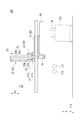
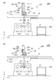
図1及び図2は、第1実施形態に係るローダ装置100の一例を示す図である。図1は、ローダ装置100を+Z側から見たときの例を示している。図2は、ローダ装置100を+X側から見たときの例を示している。
<First Embodiment>
FIG.1 and FIG.2 is a figure which shows an example of the loader apparatus 100 which concerns on 1st Embodiment. FIG. 1 shows an example when the loader device 100 is viewed from the + Z side. FIG. 2 shows an example when the loader device 100 is viewed from the + X side.

図1及び図2に示すように、ローダ装置100は、ワーク保持部10と、移動機構20と、複数の保護案内部材30とを備えている。ローダ装置100は、例えば後述の工作機械に搭載されて用いられ、この工作機械に設けられる主軸111、112とワーク搬入部120と(いずれも図1及び図2に一点鎖線で示す)の間でワークWを搬送する。   As shown in FIGS. 1 and 2, the loader device 100 includes a workpiece holding unit 10, a moving mechanism 20, and a plurality of protective guide members 30. The loader device 100 is used by being mounted on, for example, a machine tool to be described later, and between the main spindles 111 and 112 and the work carry-in portion 120 provided on the machine tool (both shown by a one-dot chain line in FIGS. 1 and 2). The work W is conveyed.

ワーク保持部10は、図2に示すように、ローダヘッド11を有している。ローダヘッド11は、ワークWを把持するチャック12、13を有している。チャック12、13は、一方が主軸111に対面する姿勢(−Z方向に向いた姿勢)に配置され、他方が床面に対面する姿勢(−Y方向に向いた姿勢)に配置される。   As illustrated in FIG. 2, the work holding unit 10 includes a loader head 11. The loader head 11 has chucks 12 and 13 for gripping the workpiece W. One of the chucks 12 and 13 is disposed in a posture facing the main shaft 111 (a posture facing the −Z direction), and the other is disposed in a posture facing the floor (a posture facing the −Y direction).

ローダヘッド11には、2つのチャック12、13の位置を入れ替える回転機構14が設けられている。回転機構14は、Y軸に対して所定角度(例、45°)傾斜した軸周りに回転可能である。回転機構14を回転させることにより、2つのチャック12,13は、互いの位置を入れ替え可能となっている。チャック12、13は、把握爪12a、13aを有している。チャック12、13は、把握爪12a、13aによりワークWを把持する。   The loader head 11 is provided with a rotation mechanism 14 that exchanges the positions of the two chucks 12 and 13. The rotation mechanism 14 can rotate around an axis inclined at a predetermined angle (eg, 45 °) with respect to the Y axis. By rotating the rotation mechanism 14, the two chucks 12 and 13 can be interchanged with each other. The chucks 12 and 13 have grasping claws 12a and 13a. The chucks 12 and 13 hold the workpiece W by the grasping claws 12a and 13a.

図1及び図2に示すように、移動機構20は、ワーク保持部10を移動させる。移動機構20は、X移動機構21と、Z移動機構22と、Y移動機構23とを有している。
X移動機構21は、ガイドレール21aと、X移動体21bとを有している。ガイドレール21aは、X方向に平行に延びており、不図示の固定部に固定されている。ガイドレール21aは、X移動体21bを案内する。X移動体21bは、不図示の駆動部により、ガイドレール21aに沿ってX方向に移動可能となっている。X移動体21bは、XZ平面に平行な板状部とYZ平面に平行な板状部とが組み合わされた形状を有しており、+Z側から見て略L字状に形成されている(図1等参照)。
As shown in FIGS. 1 and 2, the moving mechanism 20 moves the work holding unit 10. The moving mechanism 20 includes an X moving mechanism 21, a Z moving mechanism 22, and a Y moving mechanism 23.
The X moving mechanism 21 includes a guide rail 21a and an X moving body 21b. The guide rail 21a extends in parallel to the X direction and is fixed to a fixing portion (not shown). The guide rail 21a guides the X moving body 21b. The X moving body 21b can be moved in the X direction along the guide rail 21a by a drive unit (not shown). The X moving body 21b has a shape in which a plate-like portion parallel to the XZ plane and a plate-like portion parallel to the YZ plane are combined, and is formed in a substantially L shape when viewed from the + Z side ( (See FIG. 1 etc.)

Z移動機構22は、ガイド部22aと、Z移動体22bとを有している。ガイド部22aは、X移動体21bのうちXZ平面に平行な板状部の上面(+Y側の面)に固定されている。ガイド部22aは、Z方向に平行に延びている。ガイド部22aは、Z移動体22bを案内する。Z移動体22bは、直方体状に形成されている。Z移動体22bは、不図示の駆動部により、ガイド部22aに沿ってZ方向に移動可能となっている。   The Z moving mechanism 22 includes a guide portion 22a and a Z moving body 22b. The guide portion 22a is fixed to the upper surface (the surface on the + Y side) of the plate-like portion parallel to the XZ plane in the X moving body 21b. The guide portion 22a extends in parallel with the Z direction. The guide part 22a guides the Z moving body 22b. The Z moving body 22b is formed in a rectangular parallelepiped shape. The Z moving body 22b can be moved in the Z direction along the guide portion 22a by a drive unit (not shown).

Y移動機構23は、ガイド部23aと、Y移動体23bとを有している。ガイド部23aは、Z移動体22bの+Z側の面に固定されている。ガイド部23aは、Y方向に平行に延びている。ガイド部23aは、Y移動体23bを案内する。Y移動体23bは、棒状に形成されている。Y移動体23bは、不図示の駆動部により、ガイド部23aに沿ってY方向に移動可能となっている。Y移動体23bの−Y側端部には、ワーク保持部10が固定されている。   The Y moving mechanism 23 has a guide portion 23a and a Y moving body 23b. The guide portion 23a is fixed to the + Z side surface of the Z moving body 22b. The guide part 23a extends in parallel to the Y direction. The guide part 23a guides the Y moving body 23b. The Y moving body 23b is formed in a rod shape. The Y moving body 23b can be moved in the Y direction along the guide portion 23a by a driving unit (not shown). The workpiece holding unit 10 is fixed to the −Y side end of the Y moving body 23b.

ワーク保持部10をX方向に移動させる場合、移動機構20は、X移動体21bをX方向に移動させる。このとき、Z移動体22b及びY移動体23bは、X移動体21bと一体的にX方向に移動する。この移動では、X移動体21b、Z移動体22b及びY移動体23bの間に相対的な移動は生じない。   When the workpiece holding unit 10 is moved in the X direction, the moving mechanism 20 moves the X moving body 21b in the X direction. At this time, the Z moving body 22b and the Y moving body 23b move in the X direction integrally with the X moving body 21b. In this movement, no relative movement occurs between the X moving body 21b, the Z moving body 22b, and the Y moving body 23b.

また、ワーク保持部10をZ方向に移動させる場合、移動機構20は、Z移動体22bをZ方向に移動させる。このとき、Y移動体23bはZ移動体22bと一体的にZ方向に移動するが、X移動体21bは移動しない。したがって、このZ移動体22bの移動により、Y移動体23bは、X移動体21bに対してZ方向に移動する。   Further, when moving the workpiece holding unit 10 in the Z direction, the moving mechanism 20 moves the Z moving body 22b in the Z direction. At this time, the Y moving body 23b moves in the Z direction integrally with the Z moving body 22b, but the X moving body 21b does not move. Therefore, due to the movement of the Z moving body 22b, the Y moving body 23b moves in the Z direction with respect to the X moving body 21b.

また、ワーク保持部10をY方向に移動させる場合、移動機構20は、Y移動体23bをY方向に移動させる。このとき、X移動体21b及びZ移動体22bは移動しない。したがって、このY移動体23bの移動により、Y移動体23bは、X移動体21b及びZ移動体22bの両方に対してY方向に移動する。   Further, when moving the workpiece holding unit 10 in the Y direction, the moving mechanism 20 moves the Y moving body 23b in the Y direction. At this time, the X moving body 21b and the Z moving body 22b do not move. Therefore, due to the movement of the Y moving body 23b, the Y moving body 23b moves in the Y direction with respect to both the X moving body 21b and the Z moving body 22b.

複数の保護案内部材30は、第1保護案内部材31と、第2保護案内部材32と、第3保護案内部材33とを有している。第1保護案内部材31、第2保護案内部材32、及び第3保護案内部材33は、それぞれ、チャック12、13の電源供給用ケーブルなど、各種ケーブル類を収容する。   The plurality of protection guide members 30 include a first protection guide member 31, a second protection guide member 32, and a third protection guide member 33. The first protection guide member 31, the second protection guide member 32, and the third protection guide member 33 accommodate various cables such as power supply cables for the chucks 12 and 13, respectively.

第1保護案内部材31は、所定の位置に設けられる固定部40と、X移動体21bとを接続する。第1保護案内部材31は、複数のリンク部材が長手方向に連結されている。複数のリンク部材は、例えば後述のリンク部材34と同様の構成を有し、互いにXY平面に沿って屈曲可能に連結されている。各種ケーブル類は、例えば複数のリンク部材を連結方向に貫通するように収容される。第1保護案内部材31は、一端が固定部40に固定され、他端がX移動体21bの底面(−Y側の面)に固定されている。第1保護案内部材31は、固定部40から+X方向に延びると共に+Y側にU字状に屈曲され、X移動体21bの底面(−Y側の面)に向けて−X方向に延びるように配置される。   The 1st protection guide member 31 connects the fixed part 40 provided in a predetermined position, and the X mobile body 21b. As for the 1st protection guide member 31, the some link member is connected with the longitudinal direction. The plurality of link members have the same configuration as, for example, a link member 34 described later, and are connected to each other so as to be bent along the XY plane. Various cables are accommodated, for example, so as to penetrate a plurality of link members in the connecting direction. One end of the first protection guide member 31 is fixed to the fixing portion 40, and the other end is fixed to the bottom surface (the surface on the -Y side) of the X moving body 21b. The first protection guide member 31 extends in the + X direction from the fixed portion 40 and is bent in a U shape on the + Y side, and extends in the −X direction toward the bottom surface (the −Y side surface) of the X moving body 21b. Be placed.

第2保護案内部材32は、X移動体21bと、Z移動体22bとを接続する。第2保護案内部材32は、第1保護案内部材31と同様に、複数のリンク部材が長手方向に連結されている。複数のリンク部材は、例えば後述のリンク部材34と同様の構成を有し、互いにYZ平面に沿って屈曲可能に連結されている。各種ケーブル類は、例えば複数のリンク部材を連結方向に貫通するように収容される。第2保護案内部材32は、一端がX移動体21bのうちXZ平面に平行な板状部の上面(+Y側の面)に固定され、他端がZ移動体22bの+X側の面に固定されている。第2保護案内部材32は、X移動体21bから+Z方向に延びると共に+Y側にU字状に屈曲され、Z移動体22b側の端部が−Z方向を向くように配置される。   The second protection guide member 32 connects the X moving body 21b and the Z moving body 22b. Similar to the first protection guide member 31, the second protection guide member 32 has a plurality of link members connected in the longitudinal direction. The plurality of link members have the same configuration as, for example, a link member 34 described later, and are connected to each other so as to be bent along the YZ plane. Various cables are accommodated, for example, so as to penetrate a plurality of link members in the connecting direction. One end of the second protection guide member 32 is fixed to the upper surface (+ Y side surface) of the plate-like portion parallel to the XZ plane of the X moving body 21b, and the other end is fixed to the + X side surface of the Z moving body 22b. Has been. The second protective guide member 32 extends in the + Z direction from the X moving body 21b and is bent in a U shape on the + Y side, and is arranged so that the end on the Z moving body 22b side faces the -Z direction.

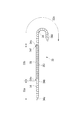
第3保護案内部材33は、X移動体21bと、Y移動体23bとを接続する。第3保護案内部材33は、屈曲範囲33a、33cと、非屈曲範囲33bとを有している。屈曲範囲33a、33cは、X移動体21bとY移動体23bとの間の相対的な移動によって変形する部分である。非屈曲範囲33bは、屈曲範囲33a、33cを除いた範囲であり、X移動体21bとY移動体23bとの間の相対的な移動によって変形しない部分である。屈曲範囲33aは、Y移動体23bに接続されている。屈曲範囲33cは、X移動体21bに接続されている。非屈曲範囲33bは、2つの屈曲範囲33a、33cに挟まれて形成される。   The third protection guide member 33 connects the X moving body 21b and the Y moving body 23b. The third protection guide member 33 has bending ranges 33a and 33c and a non-bending range 33b. The bending ranges 33a and 33c are portions that are deformed by relative movement between the X moving body 21b and the Y moving body 23b. The non-bending range 33b is a range excluding the bending ranges 33a and 33c, and is a portion that is not deformed by relative movement between the X moving body 21b and the Y moving body 23b. The bending range 33a is connected to the Y moving body 23b. The bending range 33c is connected to the X moving body 21b. The non-bending range 33b is formed between two bending ranges 33a and 33c.

第3保護案内部材33は、一端(屈曲範囲33a側の端部)がY移動体23bの−X側の面に固定され、他端(屈曲範囲33c側の端部)がX移動体21bのうちYZ平面に平行な板状部の上面(+Y側の面)に固定されている。第3保護案内部材33は、屈曲範囲33aがY移動体23bから−Y側に湾曲されて非屈曲範囲33bに接続される。非屈曲範囲33bは、直線状に配置されて屈曲範囲33cに接続される。屈曲範囲33cは、非屈曲範囲33bから−Z側に下方(−Y方向)に傾斜しつつ延び、X移動体21b側の端部が+Z方向を向くようにU字状に屈曲される。第3保護案内部材33は、Y移動体23bが第1方向D1(Y方向)及び第2方向D2(Z方向)に移動した場合に、それぞれ第1方向D1及び第2方向D2への移動に伴って変形する。   The third protective guide member 33 has one end (end on the bending range 33a side) fixed to the -X side surface of the Y moving body 23b and the other end (end on the bending range 33c side) fixed to the X moving body 21b. Of these, it is fixed to the upper surface (+ Y side surface) of the plate-like portion parallel to the YZ plane. The third protection guide member 33 is connected to the non-bending range 33b by bending the bending range 33a from the Y moving body 23b to the -Y side. The non-bending range 33b is linearly arranged and connected to the bending range 33c. The bending range 33c extends from the non-bending range 33b while inclining downward (−Y direction) toward the −Z side, and is bent in a U shape so that the end portion on the X moving body 21b side faces the + Z direction. The third protection guide member 33 moves in the first direction D1 and the second direction D2, respectively, when the Y moving body 23b moves in the first direction D1 (Y direction) and the second direction D2 (Z direction). Deforms accordingly.

図3は、第3保護案内部材33の一例を示す図である。
図3に示すように、屈曲範囲33a、33cには、それぞれ複数のリンク部材34が配置されている。複数のリンク部材34は、互いにYZ平面に沿って屈曲可能に連結されている。図3では、例えば屈曲範囲33aが直線状に伸び、屈曲範囲33cが屈曲した状態が示されているが、これに限定するものではなく、屈曲範囲33a及び33cは、共に直線状に伸びたり、屈曲したりと変形可能に構成される。
FIG. 3 is a diagram illustrating an example of the third protection guide member 33.
As shown in FIG. 3, a plurality of link members 34 are arranged in the bending ranges 33a and 33c, respectively. The plurality of link members 34 are connected to each other so as to be bendable along the YZ plane. In FIG. 3, for example, the bent range 33a extends linearly and the bent range 33c is bent. However, the present invention is not limited to this, and the bent ranges 33a and 33c both extend linearly. It can be bent and deformed.

屈曲範囲33aの長手方向の両端部には、接続リンク34a及び34bが設けられる。接続リンク34aは、Y移動体23bに接続される。接続リンク34aとY移動体23bとの間は、例えば不図示のボルトなどの固定部材を介して連結される。また、接続リンク34bは、非屈曲範囲33bに接続される。接続リンク34bと非屈曲範囲33bとの間は、例えばボルトなどの固定部材34eを介して連結される。   Connection links 34a and 34b are provided at both ends in the longitudinal direction of the bending range 33a. The connection link 34a is connected to the Y moving body 23b. The connection link 34a and the Y moving body 23b are connected via a fixing member such as a bolt (not shown), for example. The connection link 34b is connected to the non-bending range 33b. The connection link 34b and the non-bending range 33b are connected via a fixing member 34e such as a bolt.

一方、屈曲範囲33cの長手方向の両端部には、接続リンク34c及び34dが設けられる。接続リンク34cは、非屈曲範囲33bに接続される。接続リンク34cと非屈曲範囲33bとの間は、例えばボルトなどの固定部材34fを介して連結される。また、接続リンク34dは、X移動体21bに接続される。接続リンク34dとX移動体21bとの間は、例えば不図示のボルトなどの固定部材を介して連結される。   On the other hand, connection links 34c and 34d are provided at both ends of the bending range 33c in the longitudinal direction. The connection link 34c is connected to the non-bending range 33b. The connection link 34c and the non-bending range 33b are connected via a fixing member 34f such as a bolt. The connection link 34d is connected to the X mobile body 21b. The connection link 34d and the X moving body 21b are connected via a fixing member such as a bolt (not shown), for example.

非屈曲範囲33bには、接続部材35が配置されている。接続部材35は、例えば樹脂材料を用いて形成されるが、これに限られず、例えば金属材料を用いて形成されてもよい。接続部材35は、長手方向が1つのリンク部材34よりも長くなっている。なお、接続部材35として、長手方向が他のリンク部材34よりも長くなるように形成された1つのリンク部材を用いてもよい。一例として、接続部材35は、非屈曲範囲33bにわたる長さに形成されている。接続部材35は、リンク部材34の間に配置される。各種ケーブル類は、例えば複数のリンク部材34と接続部材35との間を連結方向に貫通するように収容される。   A connection member 35 is disposed in the non-bending range 33b. The connection member 35 is formed using, for example, a resin material, but is not limited thereto, and may be formed using, for example, a metal material. The connecting member 35 is longer than the one link member 34 in the longitudinal direction. In addition, as the connection member 35, you may use the one link member formed so that the longitudinal direction might become longer than the other link member 34. FIG. As an example, the connection member 35 is formed to have a length extending over the non-bending range 33b. The connecting member 35 is disposed between the link members 34. Various cables are accommodated, for example, so as to penetrate between the plurality of link members 34 and the connection member 35 in the connecting direction.

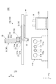
図4は、接続部材35の構成を示す斜視図である。なお、図4では、接続部材35と接続リンク34b、34cとの接続を外した状態で示している。
図4に示すように、接続部材35は、筒状に形成されており、本実施形態では例えば角筒状に形成されている。なお、接続部材35は、円筒状など、他の筒形状に形成されてもよいし、錐状に形成されてもよい。
FIG. 4 is a perspective view showing the configuration of the connection member 35. In FIG. 4, the connection member 35 and the connection links 34 b and 34 c are not connected.
As shown in FIG. 4, the connection member 35 is formed in a cylindrical shape, and in this embodiment, for example, is formed in a rectangular tube shape. The connecting member 35 may be formed in another cylindrical shape such as a cylindrical shape, or may be formed in a conical shape.

接続部材35は、内側空間35kを囲む4つの側面35a〜35dを有している。接続部材35は、例えば一部材で形成されるが、これには限定されない。接続部材35の構成として、例えば断面視でコ字状の基材の凹部に蓋部を取り付けた構成であってもよいし、例えばそのような断面視でコ字状の基材の凹部同士を対向させて固定した構成であってもよい。なお、内側空間35kには、各種ケーブル類(不図示)が収容される。4つの側面35a〜35dのうち内面側にこれらのケーブル類が固定可能な構成であってもよい。   The connection member 35 has four side surfaces 35a to 35d surrounding the inner space 35k. For example, the connection member 35 is formed of one member, but is not limited thereto. The configuration of the connecting member 35 may be, for example, a configuration in which a lid is attached to a concave portion of a U-shaped base material in a cross-sectional view. It may be configured to be opposed and fixed. Various cables (not shown) are accommodated in the inner space 35k. The structure which can fix these cables to the inner surface side among four side surfaces 35a-35d may be sufficient.

側面35aの一部には、開口部35eが形成されている。開口部35eは、接続部材35の長手方向に沿って形成されている。側面35aには、開閉部35fが設けられている。開閉部35fは、開口部35eを短手方向に跨ぐように配置されている。開閉部35fは、一端がヒンジ状に形成され、閉じた状態においては他端が側面35aに係合されている。開閉部35fは、閉じた状態で他端を外側に引っ張ることで開いた状態となる。また、開いた状態で他端を側面35aに押し込むことで閉じた状態となる。上側開閉部35fは、開閉することにより、内側空間35kを解放可能である。開閉部35fを開いた状態では、開口部35eから各種ケーブル等を収容したり、取り出したりすることが可能である。開閉部35fは、非屈曲範囲33bの長手方向に等ピッチで複数並んで配置されている。複数の開閉部35fのピッチは、リンク部材34のピッチと等しくなっている。なお、開閉部35fと同様の構成がリンク部材34に設けられてもよい。側面35aのうち長手方向の両端には、それぞれ貫通穴35g、35hが形成されている。貫通穴35g、35hには、上記の固定部材34e、34fが挿入される。   An opening 35e is formed in a part of the side surface 35a. The opening 35 e is formed along the longitudinal direction of the connection member 35. An opening / closing portion 35f is provided on the side surface 35a. The opening / closing part 35f is disposed so as to straddle the opening part 35e in the lateral direction. One end of the opening / closing part 35f is formed in a hinge shape, and in the closed state, the other end is engaged with the side surface 35a. The opening / closing part 35f is opened by pulling the other end outward in a closed state. Moreover, it will be in the closed state by pushing an other end into the side surface 35a in the open state. The upper opening / closing part 35f can open and close the inner space 35k by opening and closing. When the opening / closing part 35f is opened, various cables and the like can be accommodated and taken out from the opening 35e. A plurality of opening / closing portions 35f are arranged side by side at equal pitches in the longitudinal direction of the non-bending range 33b. The pitch of the plurality of opening / closing portions 35 f is equal to the pitch of the link members 34. The link member 34 may be provided with the same configuration as the opening / closing part 35f. Through holes 35g and 35h are formed at both ends in the longitudinal direction of the side surface 35a. The fixing members 34e and 34f are inserted into the through holes 35g and 35h.

接続部材35は、長手方向における単位長さあたりの重量がリンク部材34と同一に設定されている。一例として、接続部材35の側面35b、35cには、複数の貫通穴35iが形成されている。複数の貫通穴35iにより、接続部材35の長手方向における単位長さあたりの重量がリンク部材34と同一になるように調整されている。これにより、第3保護案内部材33の全長に亘って力が偏り無く伝達される。貫通穴35iは、例えば円形に形成されるが、これには限定されず、多角形など他の形状であってもよい。また、貫通穴35iは、側面35b及び35cの一方にのみ設けられてもよいし、側面35dに設けられてもよい。また、貫通穴35iは、設けられなくてもよい。   The connection member 35 has the same weight per unit length in the longitudinal direction as that of the link member 34. As an example, a plurality of through holes 35 i are formed in the side surfaces 35 b and 35 c of the connection member 35. The plurality of through holes 35 i are adjusted so that the weight per unit length in the longitudinal direction of the connection member 35 is the same as that of the link member 34. As a result, the force is transmitted evenly over the entire length of the third protective guide member 33. The through hole 35i is formed, for example, in a circular shape, but is not limited thereto, and may be another shape such as a polygon. The through hole 35i may be provided only on one of the side surfaces 35b and 35c, or may be provided on the side surface 35d. Further, the through hole 35i may not be provided.

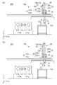
次に、上記のように構成されたローダ装置100の動作について図面を用いて説明する。図5は、ローダ装置100の動作の一例を示す図であり、(a)は図2に示す状態に対してY移動体23bを第1方向D1(−Y方向)に移動させる場合の例を示し、(b)は(a)の状態に対してZ移動体22bを第2方向D2(−Z方向)に移動させる場合の例を示す。   Next, the operation of the loader device 100 configured as described above will be described with reference to the drawings. FIG. 5 is a diagram illustrating an example of the operation of the loader device 100. FIG. 5A illustrates an example in which the Y moving body 23b is moved in the first direction D1 (−Y direction) with respect to the state illustrated in FIG. (B) shows the example in the case of moving the Z moving body 22b to the 2nd direction D2 (-Z direction) with respect to the state of (a).

図5(a)に示すように、Y移動体23bを第1方向D1である−Y方向に移動させた場合、第3保護案内部材33の接続リンク34aが−Y方向に引っ張られる。なお、このような移動は、例えばワーク搬入部120に載置されるワークWを取りに行く場合や、ワーク保持部10にワークWが保持された状態で主軸111(又は112)にワークWを対向させる場合に行われる。この移動による力は、まず屈曲範囲33aに伝達される。屈曲範囲33aでは、リンク部材34の1つ1つに力が順に伝達される。この力の伝達により、屈曲範囲33aのリンク部材34は、Y移動体23bの移動に追従するように屈曲する。リンク部材34が変形する場合、リンク部材34同士の摩擦音や衝突音が発生する。   As shown in FIG. 5A, when the Y moving body 23b is moved in the -Y direction that is the first direction D1, the connection link 34a of the third protective guide member 33 is pulled in the -Y direction. Such movement is performed when, for example, the workpiece W placed on the workpiece loading unit 120 is taken or when the workpiece W is held by the workpiece holding unit 10 while the workpiece W is held on the spindle 111 (or 112). This is done when facing each other. The force due to this movement is first transmitted to the bending range 33a. In the bending range 33a, force is transmitted to each of the link members 34 in order. By transmitting this force, the link member 34 in the bending range 33a is bent so as to follow the movement of the Y moving body 23b. When the link member 34 is deformed, a frictional sound or a collision sound between the link members 34 is generated.

次に、接続リンク34bを介して非屈曲範囲33bの接続部材35に力が伝達される。接続部材35が非屈曲範囲33bにわたる長さに形成されているため、複数のリンク34を順に伝わる場合に比べて短時間で力が伝達される。接続部材35を伝達した力は、接続リンク34cを介して屈曲範囲33cに伝達される。   Next, force is transmitted to the connection member 35 in the non-bending range 33b via the connection link 34b. Since the connection member 35 is formed to have a length extending over the non-bending range 33b, the force is transmitted in a shorter time than when the plurality of links 34 are transmitted in order. The force transmitted through the connection member 35 is transmitted to the bending range 33c through the connection link 34c.

屈曲範囲33cでは、屈曲範囲33aと同様に、リンク部材34の1つ1つに順に力が伝達される。この力の伝達により、屈曲範囲33cのリンク部材34は、Y移動体23bの移動に追従するように屈曲状態を変化させる。リンク部材34が変形する場合、リンク部材34同士の摩擦音や衝突音が発生する。   In the bending range 33c, as in the bending range 33a, force is transmitted to each of the link members 34 in order. By transmitting this force, the link member 34 in the bending range 33c changes the bending state so as to follow the movement of the Y moving body 23b. When the link member 34 is deformed, a frictional sound or a collision sound between the link members 34 is generated.

上記動作において、例えば第3保護案内部材33の全長に亘ってリンク部材34が配置される場合には、Y移動体23bの移動による力がリンク部材34の1つ1つを介して伝達される。このため、X移動体21b側まで力が伝達するまで時間がかかる。したがって、Y移動体23bの移動が停止した後も第3保護案内部材33が変形し、リンク部材34同士の摩擦音や衝突音が発生する。Y移動体23bの移動中では、リンク部材34同士の摩擦音や衝突音はY移動体23bの移動音によってかき消されるため目立たない。しかし、Y移動体23bの移動が停止した後は移動音が停止しているため、リンク部材34同士の摩擦音や衝突音が騒音として目立ってしまう。   In the above operation, for example, when the link member 34 is disposed over the entire length of the third protection guide member 33, the force due to the movement of the Y moving body 23 b is transmitted through each of the link members 34. . For this reason, it takes time until the force is transmitted to the X moving body 21b side. Therefore, even after the movement of the Y moving body 23b is stopped, the third protective guide member 33 is deformed, and a frictional sound or a collision sound between the link members 34 is generated. During the movement of the Y moving body 23b, the friction sound and the collision sound between the link members 34 are erased by the moving sound of the Y moving body 23b, so that they are not conspicuous. However, since the moving sound is stopped after the movement of the Y moving body 23b is stopped, the frictional sound and the collision sound between the link members 34 are conspicuous as noise.

これに対して、本実施形態に係る第3保護案内部材33は、非屈曲範囲33bに接続部材35が設けられるため、全長に亘ってリンク部材34が配置される構成に比べて、移動による力が短時間で伝達され、第3保護案内部材33全体の変形が短時間で行われる。これにより、Y移動体23bの移動が停止した後に第3保護案内部材33が遅れて変形するのを防ぐことができる。このため、Y移動体23bの移動後に生じる第3保護案内部材33の騒音を低減することができる。なお、上記説明では、Y移動体23bが第1方向D1として−Y方向に移動する場合を例に挙げたが、Y移動体23bが+Y方向に移動する場合にも同様に、Y移動体23bの移動後に生じる第3保護案内部材33の騒音を低減することができる。   On the other hand, the third protective guide member 33 according to the present embodiment is provided with the connection member 35 in the non-bending range 33b. Therefore, the third protective guide member 33 has a force by movement compared to the configuration in which the link member 34 is disposed over the entire length. Is transmitted in a short time, and the entire third protective guide member 33 is deformed in a short time. Thereby, it is possible to prevent the third protective guide member 33 from being deformed with a delay after the movement of the Y moving body 23b is stopped. For this reason, the noise of the 3rd protection guide member 33 which arises after the movement of the Y mobile body 23b can be reduced. In the above description, the case where the Y moving body 23b moves in the −Y direction as the first direction D1 has been described as an example, but the Y moving body 23b similarly applies when the Y moving body 23b moves in the + Y direction. It is possible to reduce the noise of the third protective guide member 33 that occurs after the movement of.

また、図5(b)に示すように、Z移動体22bを第2方向D2である−Z方向に移動させた場合、Z移動体22bの移動に伴って第2保護案内部材32の屈曲状態が変化する。また、Z移動体22bと一体にY移動体23bが−Z方向に移動する。なお、このような移動は、例えば主軸111(又は112)にワークWを対向させた状態から、その主軸111(又は112)にワークWを保持させる場合(主軸にワークを渡す場合)に行われる。このY移動体23bの移動に伴って、第3保護案内部材33の接続リンク34aが−Z方向に押される。この力は、屈曲範囲33aのリンク部材34の1つ1つに順に伝達され、リンク部材34同士の摩擦音や衝突音が発生する。   Further, as shown in FIG. 5B, when the Z moving body 22b is moved in the −Z direction, which is the second direction D2, the second protection guide member 32 is bent along with the movement of the Z moving body 22b. Changes. Further, the Y moving body 23b moves in the −Z direction integrally with the Z moving body 22b. Such movement is performed, for example, when the workpiece W is held on the spindle 111 (or 112) from the state where the workpiece W is opposed to the spindle 111 (or 112) (when the workpiece is transferred to the spindle). . With the movement of the Y moving body 23b, the connection link 34a of the third protection guide member 33 is pushed in the −Z direction. This force is transmitted to each of the link members 34 in the bending range 33a in order, and a frictional sound or a collision sound between the link members 34 is generated.

次に、接続リンク34bを介して非屈曲範囲33bの接続部材35に力が伝達される。この力は、短時間で接続リンク34cを介して屈曲範囲33cに伝達される。屈曲範囲33cでは、リンク部材34の1つ1つに順に力が伝達されて屈曲状態が変化すると共に、リンク部材34同士の摩擦音や衝突音が発生する。この場合においても同様に、第3保護案内部材33全体の変形が短時間で行われるため、Y移動体23bの移動が停止した後に第3保護案内部材33が遅れて変形するのを防ぐことができる。このため、Z移動体22bと一体で移動する場合においても、Y移動体23bの移動後に生じる第3保護案内部材33の騒音を低減することができる。なお、上記説明では、Y移動体23bが第2方向D2として−Z方向に移動する場合を例に挙げたが、Y移動体23bが+Z方向に移動する場合にも同様に、Y移動体23bの移動後に生じる第3保護案内部材33の騒音を低減することができる。   Next, force is transmitted to the connection member 35 in the non-bending range 33b via the connection link 34b. This force is transmitted to the bending range 33c through the connection link 34c in a short time. In the bending range 33c, force is transmitted to each of the link members 34 in order to change the bending state, and frictional and collision sounds between the link members 34 are generated. In this case as well, since the entire third protection guide member 33 is deformed in a short time, it is possible to prevent the third protection guide member 33 from being deformed with delay after the movement of the Y moving body 23b is stopped. it can. For this reason, even when moving integrally with the Z moving body 22b, the noise of the third protection guide member 33 generated after the Y moving body 23b moves can be reduced. In the above description, the case where the Y moving body 23b moves in the −Z direction as the second direction D2 has been described as an example. However, when the Y moving body 23b moves in the + Z direction, the Y moving body 23b It is possible to reduce the noise of the third protective guide member 33 that occurs after the movement of.

以上のように、第1実施形態では、屈曲範囲33a、33cに配置される1つのリンク部材34より長手方向が長い接続部材35が第3保護案内部材33の非屈曲範囲33bに配置されるため、非屈曲範囲33bでは屈曲範囲33aに比べて力の伝達速度が速くなる。このため、第3保護案内部材33の全長に亘ってリンク部材34が配置される構成に比べて、第3保護案内部材33全体の変形が短時間で行われる。これにより、Y移動体23bの移動が停止した後に第3保護案内部材33が遅れて変形するのを防ぐことができるため、Y移動体23bの移動後に生じる第3保護案内部材33の騒音を低減することができる。   As described above, in the first embodiment, the connection member 35 having a longer longitudinal direction than the one link member 34 disposed in the bending ranges 33 a and 33 c is disposed in the non-bending range 33 b of the third protective guide member 33. In the non-bending range 33b, the force transmission speed is faster than in the bending range 33a. For this reason, compared with the structure in which the link member 34 is arrange | positioned over the full length of the 3rd protection guide member 33, the deformation | transformation of the 3rd protection guide member 33 whole is performed in a short time. Accordingly, the third protective guide member 33 can be prevented from being deformed with a delay after the movement of the Y movable body 23b is stopped, so that the noise of the third protective guide member 33 generated after the movement of the Y movable body 23b is reduced. can do.

また、Y移動体23bは、Y方向(第1方向D1)及びZ方向(第2方向D2)に移動可能であるが、第1方向D1の移動距離に比べて第2方向の移動距離が小さくなっている。このように、第1方向D1と第2方向D2とで移動距離に差がある場合、非屈曲範囲33bを長く確保することができる。   The Y moving body 23b can move in the Y direction (first direction D1) and the Z direction (second direction D2), but the moving distance in the second direction is smaller than the moving distance in the first direction D1. It has become. Thus, when there is a difference in the movement distance between the first direction D1 and the second direction D2, the non-bending range 33b can be secured long.

また、保護案内部材30の変形の遅れは、移動体の移動速度が高くなるほど発生しやすくなる。第1実施形態では、比較的移動速度の高いY移動体23bに第3保護案内部材33が接続されるため、第3保護案内部材33の変形の遅れを効率的に防止することができる。   Further, the deformation delay of the protection guide member 30 is more likely to occur as the moving speed of the moving body increases. In the first embodiment, since the third protection guide member 33 is connected to the Y moving body 23b having a relatively high movement speed, it is possible to efficiently prevent a delay in deformation of the third protection guide member 33.

<第2実施形態>
次に、第2実施形態を説明する。第2実施形態では、第1実施形態に記載のローダ装置100を備える工作機械を例に挙げて説明する。第2実施形態では、第1実施形態と共通のXYZ直交座標系を用いて説明する。ただし、第2実施形態では、主軸111、112の回転軸方向をZ方向とし、ワークWに対する切削量を規定する方向をX方向とする。
Second Embodiment
Next, a second embodiment will be described. In the second embodiment, a machine tool including the loader device 100 described in the first embodiment will be described as an example. The second embodiment will be described using an XYZ orthogonal coordinate system common to the first embodiment. However, in 2nd Embodiment, let the rotating shaft direction of the main shafts 111 and 112 be a Z direction, and let the direction which prescribe | regulate the cutting amount with respect to the workpiece | work W be an X direction.

図6は、第2実施形態に係る工作機械200の一例を示す図である。図6に示す工作機械200は、例えば平行2軸旋盤である。図6において、工作機械200の+Z側が正面であり、−Z側が背面である。また、工作機械200の±X側は側面であり、X方向は工作機械200の左右方向である。   FIG. 6 is a diagram illustrating an example of a machine tool 200 according to the second embodiment. A machine tool 200 shown in FIG. 6 is, for example, a parallel twin-axis lathe. In FIG. 6, the + Z side of the machine tool 200 is the front surface, and the −Z side is the back surface. Further, the ± X side of the machine tool 200 is a side surface, and the X direction is the left-right direction of the machine tool 200.

工作機械200は、本体部110と、ワーク搬入部120と、ローダ装置130とを有している。
本体部110は、主軸111、112と、タレット113、114とを有している。主軸111、112は、X方向に並んで配置されている。主軸111、112は、不図示の軸受け等によって回転可能に支持されている。主軸111、112の+Z側の端部には、それぞれ把握爪111a、112aが設けられている。把握爪111a、112aは、主軸111、112の回転軸周りに所定の間隔で複数配置されている。把握爪111a、112aは、主軸111、112の径方向に移動させることでワークWを保持可能である。
The machine tool 200 includes a main body 110, a work loading unit 120, and a loader device 130.
The main body 110 has main shafts 111 and 112 and turrets 113 and 114. The main shafts 111 and 112 are arranged side by side in the X direction. The main shafts 111 and 112 are rotatably supported by a bearing (not shown) or the like. Grasping claws 111a and 112a are provided on the + Z side ends of the main shafts 111 and 112, respectively. A plurality of grasping claws 111 a and 112 a are arranged around the rotation axes of the main shafts 111 and 112 at a predetermined interval. The grasping claws 111 a and 112 a can hold the workpiece W by moving in the radial direction of the main shafts 111 and 112.

タレット113は、主軸111の+X側に配置されている。タレット114は、主軸112の−X側に配置されている。タレット113、114のそれぞれには、モータ等の回転駆動装置が設けられている。タレット113、114は、回転駆動装置により、Z方向に平行な軸周りに回転可能となっている。タレット113、114の周面には、切削工具を保持するための複数の保持部が設けられている(不図示)。これら保持部の全部または一部には切削工具が保持される。したがって、タレット113、114を回転させることにより、所望の切削工具が選択される。タレット113、114の保持部に保持される切削工具は、各保持台に対して交換可能である。切削工具としては、ワークWに対して切削加工を施すバイト等の他、ドリルやエンドミル等の回転工具が用いられてもよい。また、タレット113、114は、不図示の駆動装置により、X方向、Y方向、及びZ方向に移動可能となっている。これにより、切削工具は、ワークWに対してX方向、Y方向、及びZ方向に移動可能となっている。   The turret 113 is disposed on the + X side of the main shaft 111. The turret 114 is disposed on the −X side of the main shaft 112. Each of the turrets 113 and 114 is provided with a rotational drive device such as a motor. The turrets 113 and 114 can be rotated around an axis parallel to the Z direction by a rotary drive device. A plurality of holding portions for holding the cutting tool are provided on the peripheral surfaces of the turrets 113 and 114 (not shown). A cutting tool is held on all or part of these holding portions. Therefore, a desired cutting tool is selected by rotating the turrets 113 and 114. The cutting tools held in the holding portions of the turrets 113 and 114 can be exchanged for each holding table. As the cutting tool, a rotating tool such as a drill or an end mill may be used in addition to a cutting tool for cutting the workpiece W. Further, the turrets 113 and 114 can be moved in the X direction, the Y direction, and the Z direction by a driving device (not shown). Thereby, the cutting tool can move in the X direction, the Y direction, and the Z direction with respect to the workpiece W.

ワーク搬入部120には、工作機械200における加工対象であるワークWが載置される。ワーク搬入部120としては、例えば固定台が用いられるが、これに限定されるものではなく、コンベアやロータリー式の台などが用いられてもよい。
ローダ装置130は、第1実施形態に記載のローダ装置100が用いられる。ローダ装置130は、ワーク保持部10が主軸111、112とワーク搬入部120との間で移動可能となるように、X移動機構21のガイドレール21aが本体部110とワーク搬入部120との間をX方向に跨ぐように配置されている。これにより、ローダ装置130は、主軸111、112とワーク搬入部120との間でワークWを搬送可能となっている。
A workpiece W that is a processing target in the machine tool 200 is placed on the workpiece loading unit 120. For example, a fixed table is used as the workpiece loading unit 120, but the workpiece loading unit 120 is not limited thereto, and a conveyor, a rotary table, or the like may be used.
As the loader device 130, the loader device 100 described in the first embodiment is used. In the loader device 130, the guide rail 21 a of the X moving mechanism 21 is located between the main body 110 and the workpiece loading unit 120 so that the workpiece holding unit 10 can move between the spindles 111 and 112 and the workpiece loading unit 120. Are arranged so as to straddle the X direction. Thereby, the loader device 130 can transport the workpiece W between the spindles 111 and 112 and the workpiece loading unit 120.

次に、上記のように構成された工作機械200の動作を説明する。図7及び図8は、工作機械200の動作の一例を示す図である。
まず、ローダ装置130は、ワーク保持部10をワーク搬入部120の上方(+Y側)に配置させる。その後、図7(a)に示すように、ローダヘッド11のチャック12を下側(−Y方向)に向けた状態でY移動体23bを−Y方向に移動させ、把握爪12aによってワークWを把持させる。このとき、Y移動体23bの移動に伴い、第3保護案内部材33が変形する。第3保護案内部材33には、屈曲範囲33a、非屈曲範囲33b、及び屈曲範囲33cの順に力が伝達される。この力は、非屈曲範囲33bを構成する接続部材35を介して短時間で伝達されるため、第3保護案内部材33全体の変形が短時間で行われる。このため、Y移動体23bの移動が停止した後に第3保護案内部材33が遅れて変形するのを防止でき、Y移動体23bの移動後に生じる第3保護案内部材33の騒音を低減できる。
Next, the operation of the machine tool 200 configured as described above will be described. 7 and 8 are diagrams illustrating an example of the operation of the machine tool 200. FIG.
First, the loader device 130 places the workpiece holding unit 10 above (on the + Y side) the workpiece loading unit 120. Thereafter, as shown in FIG. 7A, the Y moving body 23b is moved in the -Y direction with the chuck 12 of the loader head 11 directed downward (-Y direction), and the workpiece W is moved by the grasping claws 12a. Hold it. At this time, the third protection guide member 33 is deformed with the movement of the Y moving body 23b. A force is transmitted to the third protective guide member 33 in the order of the bending range 33a, the non-bending range 33b, and the bending range 33c. Since this force is transmitted in a short time via the connection member 35 constituting the non-bending range 33b, the entire third protective guide member 33 is deformed in a short time. For this reason, it is possible to prevent the third protective guide member 33 from being deformed with a delay after the movement of the Y movable body 23b is stopped, and it is possible to reduce the noise of the third protective guide member 33 generated after the movement of the Y movable body 23b.

その後、回転機構14によってチャック12とチャック13とを入れ替える。これにより、チャック12及びワークWが−Z方向に向けられ、チャック13が−Y方向に向けられる。チャック12を−Z方向に向けた後、図7(b)に示すように、Y移動体23bを+Y方向に移動させ、ワークWを引き上げる。このとき、Y移動体23bの移動に伴って第3保護案内部材33が変形する。この場合においても、Y移動体23bの移動が停止した後に第3保護案内部材33が遅れて変形するのを防止でき、Y移動体23bの移動後に生じる第3保護案内部材33の騒音を低減できる。なお、ワークWを引き上げた後にチャック12を−Z方向に向けてもよい。   Thereafter, the chuck 12 and the chuck 13 are exchanged by the rotation mechanism 14. Accordingly, the chuck 12 and the workpiece W are directed in the −Z direction, and the chuck 13 is directed in the −Y direction. After the chuck 12 is directed in the −Z direction, the Y moving body 23b is moved in the + Y direction as shown in FIG. At this time, the third protection guide member 33 is deformed with the movement of the Y moving body 23b. Even in this case, it is possible to prevent the third protection guide member 33 from being deformed after the movement of the Y moving body 23b is stopped, and to reduce the noise of the third protection guide member 33 generated after the movement of the Y moving body 23b. . Note that the chuck 12 may be directed in the −Z direction after the workpiece W is pulled up.

次に、図8(a)に示すように、X移動体21bを−X方向に移動させ、ワーク保持部10及びワークWを例えば主軸111の上方(+Y側)に配置させる。以下、ワークWを主軸111に配置する場合を例に挙げて説明する。なお、ワークWを主軸112に配置する場合には、主軸112の上方にワーク保持部10及びワークWを配置させる。このとき、X移動体21bの移動に応じて第1保護案内部材31が変形する。   Next, as illustrated in FIG. 8A, the X moving body 21 b is moved in the −X direction, and the work holding unit 10 and the work W are disposed, for example, above the main shaft 111 (+ Y side). Hereinafter, a case where the workpiece W is arranged on the spindle 111 will be described as an example. When the work W is disposed on the main shaft 112, the work holding unit 10 and the work W are disposed above the main shaft 112. At this time, the first protection guide member 31 is deformed in accordance with the movement of the X moving body 21b.

次に、図8(b)に示すように、Y移動体23bを−Y方向に移動させ、ワークWを主軸111に対向させる。このとき、Y移動体23bの移動に伴って第3保護案内部材33が変形する。したがって、この場合においても、Y移動体23bの移動が停止した後に第3保護案内部材33が遅れて変形するのを防止でき、Y移動体23bの移動後に生じる第3保護案内部材33の騒音を低減できる。   Next, as shown in FIG. 8B, the Y moving body 23 b is moved in the −Y direction so that the workpiece W is opposed to the main shaft 111. At this time, the third protection guide member 33 is deformed with the movement of the Y moving body 23b. Therefore, in this case as well, the third protective guide member 33 can be prevented from being deformed with a delay after the movement of the Y movable body 23b is stopped, and the noise of the third protective guide member 33 generated after the movement of the Y movable body 23b can be prevented. Can be reduced.

次に、図8(b)に示す状態から、Z移動体22bを−Z方向に移動させ、ワークWを主軸111の把握爪111aに保持させる。このとき、Z移動体22bの移動に伴って第2保護案内部材32が変形する。また、Z移動体22bと一体にY移動体23bが移動する。このY移動体23bの移動に伴って第3保護案内部材33が変形する。この場合、第1実施形態の図5(b)に示す場合と同様に、Y移動体23bの移動に伴って、屈曲範囲33a、非屈曲範囲33b、屈曲範囲33cの順に力が−Z方向に短時間で伝達される。このため、第3保護案内部材33全体の変形が短時間で行われる。よって、Y移動体23bの移動後に生じる第3保護案内部材33の騒音を低減できる。   Next, from the state shown in FIG. 8B, the Z moving body 22 b is moved in the −Z direction, and the work W is held on the grasping claw 111 a of the spindle 111. At this time, the second protection guide member 32 is deformed with the movement of the Z moving body 22b. Further, the Y moving body 23b moves integrally with the Z moving body 22b. As the Y moving body 23b moves, the third protective guide member 33 is deformed. In this case, as in the case shown in FIG. 5B of the first embodiment, the force moves in the −Z direction in the order of the bending range 33a, the non-bending range 33b, and the bending range 33c as the Y moving body 23b moves. It is transmitted in a short time. For this reason, the deformation | transformation of the 3rd protection guide member 33 whole is performed in a short time. Therefore, the noise of the 3rd protection guide member 33 which arises after movement of Y movable object 23b can be reduced.

以上のように、第2実施形態によれば、加工対象のワークWを保持する主軸111,112を備える工作機械200であって、ワーク搬入部120と主軸111、112との間においてワークWを搬送するローダ装置130を備え、このローダ装置130として、第1実施形態に記載のローダ装置100が用いられるため、Y移動体23bの移動が停止した後に第3保護案内部材33が遅れて変形するのを防ぐことができるため、Y移動体23bの移動後に生じる第3保護案内部材33の騒音を低減することができる。また、これにより、騒音の少ない工作機械200を得ることができる。   As described above, according to the second embodiment, the machine tool 200 includes the spindles 111 and 112 that hold the workpiece W to be processed, and the workpiece W is placed between the workpiece loading unit 120 and the spindles 111 and 112. Since the loader device 130 described in the first embodiment is used as the loader device 130, the third protective guide member 33 is deformed with a delay after the movement of the Y moving body 23b is stopped. Therefore, the noise of the third protective guide member 33 generated after the Y moving body 23b is moved can be reduced. Thereby, the machine tool 200 with less noise can be obtained.

以上、実施形態について説明したが、本発明は、上述した説明に限定されるものではなく、本発明の要旨を逸脱しない範囲において種々の変更が可能である。
例えば、上記実施形態では、接続部材35が長手方向に直線状に形成された構成を例に挙げて説明したが、これに限定するものではない。例えば、接続部材35が長手方向に湾曲した形状であってもよいし、屈曲した形状であってもよい。
The embodiment has been described above, but the present invention is not limited to the above description, and various modifications can be made without departing from the gist of the present invention.
For example, in the above-described embodiment, the configuration in which the connection member 35 is linearly formed in the longitudinal direction has been described as an example, but the present invention is not limited to this. For example, the connecting member 35 may have a shape that is curved in the longitudinal direction, or may have a bent shape.

また、上記実施形態では、非屈曲範囲33b(接続部材35)が屈曲範囲33a、33cに挟まれた構成を例に挙げて説明したが、これに限定するものではない。例えば、屈曲範囲33a及び33cのうち一方を省略した構成としてもよい。屈曲範囲33cを省略した場合、Y移動体23bに屈曲範囲33aが接続され、X移動体21bに非屈曲範囲33bが接続される。また、屈曲範囲33aを省略した場合、Y移動体23bに非屈曲範囲33bが接続され、X移動体21bに屈曲範囲33cが接続される。いずれの場合であっても、Y移動体23bの移動による力を短時間で伝達することができるため、Y移動体23bの移動後に生じる第3保護案内部材33の騒音を低減できる。   In the above-described embodiment, the configuration in which the non-bending range 33b (connection member 35) is sandwiched between the bending ranges 33a and 33c has been described as an example. However, the present invention is not limited to this. For example, one of the bending ranges 33a and 33c may be omitted. When the bending range 33c is omitted, the bending range 33a is connected to the Y moving body 23b, and the non-bending range 33b is connected to the X moving body 21b. When the bending range 33a is omitted, the non-bending range 33b is connected to the Y moving body 23b, and the bending range 33c is connected to the X moving body 21b. In any case, since the force due to the movement of the Y moving body 23b can be transmitted in a short time, the noise of the third protective guide member 33 generated after the movement of the Y moving body 23b can be reduced.

また、上記実施形態では、第3保護案内部材33の長手方向に接続部材35が1つだけ設けられた構成を例に挙げて説明したが、これに限定するものではなく、2つ以上の接続部材35が設けられた構成であってもよい。この場合、接続部材35同士を直接連結した構成であってもよいし、接続部材35同士の間に複数のリンク部材34を挟んだ構成であってもよい。   In the above embodiment, the configuration in which only one connection member 35 is provided in the longitudinal direction of the third protective guide member 33 has been described as an example. However, the present invention is not limited to this, and two or more connections are provided. The structure provided with the member 35 may be sufficient. In this case, the connection member 35 may be directly connected, or a plurality of link members 34 may be sandwiched between the connection members 35.

また、上記実施形態では、長手方向において接続部材35が非屈曲範囲33bの全範囲にわたって配置された構成を例に挙げて説明したが、これに限定するものではない。例えば、接続部材35が1つの非屈曲範囲33bにおいて複数に分割された構成であってもよい。また、非屈曲範囲33bの一部の範囲にのみ接続部材35が配置され、残りの部分に例えばリンク部材34などが配置された構成であってもよい。   Moreover, although the said embodiment gave and demonstrated as an example the structure by which the connection member 35 was arrange | positioned over the whole range of the non-bending range 33b in the longitudinal direction, it is not limited to this. For example, the connection member 35 may be divided into a plurality of portions in one non-bending range 33b. Alternatively, the connection member 35 may be disposed only in a part of the non-bending range 33b, and the link member 34 may be disposed in the remaining part.

また、上記実施形態では、ローダ装置100が、ワークWを搬入するワーク搬入部120と主軸111、112との間でワークWを搬送する場合を例に挙げて説明したが、これに限定するものではない。例えば、ワークWを搬出するワーク搬出部が別途設けられる場合、ローダ装置100が主軸111、112とワーク搬出部との間でワークWを搬送する構成であってもよい。   In the above-described embodiment, the loader device 100 has been described by taking as an example the case where the workpiece W is transferred between the workpiece loading unit 120 for loading the workpiece W and the spindles 111 and 112. However, the present invention is limited to this. is not. For example, when a workpiece unloading unit for unloading the workpiece W is separately provided, the loader device 100 may be configured to convey the workpiece W between the spindles 111 and 112 and the workpiece unloading unit.

また、上記実施形態では、ローダ装置100が、1つのワーク保持部10に対する移動機構20及び保護案内部材30を有する構成を例に挙げて説明したが、これに限定するものではない。例えば、ワーク保持部10が複数設けられ、この複数のワーク保持部10に対する移動機構20及び保護案内部材30が複数組設けられた構成であってもよい。この場合、各組の保護案内部材30に配置される第3保護案内部材33に接続部材35が設けられた構成とすることができる。   In the above embodiment, the loader device 100 has been described by taking as an example the configuration in which the loader device 100 includes the moving mechanism 20 and the protective guide member 30 for one workpiece holding unit 10, but the configuration is not limited thereto. For example, a configuration in which a plurality of workpiece holding units 10 are provided and a plurality of sets of moving mechanisms 20 and protection guide members 30 for the plurality of workpiece holding units 10 may be provided. In this case, it can be set as the structure by which the connection member 35 was provided in the 3rd protection guide member 33 arrange | positioned at the protection guide member 30 of each group.

また、上記説明では、第3保護案内部材33にのみ接続部材35を配置する構成を例に挙げて説明したが、これに限定するものではない。例えば、第1保護案内部材31及び第2保護案内部材32の少なくとも一方に対して接続部材35を配置する構成であってもよい。すなわち、ローダ装置100(130)の第1方向D1及び第2方向D2が、X方向、Y方向、及びZ方向のうちいずれか2つに設定されるものであればよい。この場合、どの2つの移動方向に移動体(X移動体21b又はZ移動体22b)が移動する場合においても、保護案内部材30の騒音を防ぐことができる。   Moreover, in the said description, although the structure which arrange | positions the connection member 35 only to the 3rd protection guide member 33 was mentioned as an example, it demonstrated, It does not limit to this. For example, the connection member 35 may be disposed with respect to at least one of the first protection guide member 31 and the second protection guide member 32. That is, it is only necessary that the first direction D1 and the second direction D2 of the loader device 100 (130) are set to any two of the X direction, the Y direction, and the Z direction. In this case, the noise of the protective guide member 30 can be prevented even when the moving body (the X moving body 21b or the Z moving body 22b) moves in any two moving directions.

D1…第1方向 D2…第2方向 10…ワーク保持部 20…移動機構 21…X移動機構 21b…X移動体(固定部) 22…Z移動機構 23…Y移動機構 23b…Y移動体 30…保護案内部材 33…第3保護案内部材 33a、33c…屈曲範囲 33b…非屈曲範囲 34…リンク部材 35…接続部材 35a〜35d…側面 35k…内側空間 35f…開閉部 35i…貫通穴 40…固定部 100、130…ローダ装置 111、112…主軸 120…ワーク搬入部 200…工作機械 W…ワーク D1 ... 1st direction D2 ... 2nd direction 10 ... Work holding part 20 ... Moving mechanism 21 ... X moving mechanism 21b ... X moving body (fixed part) 22 ... Z moving mechanism 23 ... Y moving mechanism 23b ... Y moving body 30 ... Protective guide member 33 ... third protective guide member 33a, 33c ... bending range 33b ... non-bending range 34 ... link member 35 ... connecting member 35a-35d ... side surface 35k ... inside space 35f ... opening / closing part 35i ... through hole 40 ... fixing part DESCRIPTION OF SYMBOLS 100, 130 ... Loader apparatus 111, 112 ... Spindle 120 ... Work carrying-in part 200 ... Machine tool W ... Work

Claims (8)

固定部に対して少なくとも第1方向及び前記第1方向と交差する第2方向に移動する移動体と、前記移動体と前記固定部とを接続しかつケーブル類を収容する保護案内部材と、を備え、前記移動体の移動によりワークを搬送するローダ装置であって、
前記保護案内部材は、全長のうち屈曲範囲に配置されかつ屈曲可能に連結される複数のリンク部材と、前記屈曲範囲を除いた非屈曲範囲に配置されかつ1つの前記リンク部材より長手方向が長い接続部材と、が接続されて形成されるローダ装置。
A moving body that moves at least in a first direction and a second direction that intersects the first direction with respect to the fixed portion; and a protective guide member that connects the movable body and the fixed portion and accommodates cables and the like. A loader device that conveys a workpiece by movement of the movable body,
The protective guide member is arranged in a bending range of the entire length and is connected to bendable, and is disposed in a non-bending range excluding the bending range and longer in the longitudinal direction than one link member. A loader device formed by connecting a connection member.
前記非屈曲範囲は、前記屈曲範囲に挟まれて形成され、
前記接続部材は、前記リンク部材の間に配置される請求項1記載のローダ装置。
The non-bending range is formed between the bending ranges,
The loader device according to claim 1, wherein the connection member is disposed between the link members.
前記接続部材は、前記非屈曲範囲にわたる長さに形成される請求項1または請求項2記載のローダ装置。   The loader device according to claim 1, wherein the connection member is formed to have a length over the non-bending range. 前記接続部材は、筒状に形成されるとともに、側面に内側空間を開放可能な開閉部を備える請求項1〜請求項3のいずれか1項に記載のローダ装置。   The loader device according to any one of claims 1 to 3, wherein the connection member is formed in a cylindrical shape and includes an opening / closing portion that can open an inner space on a side surface. 前記接続部材は、長手方向における単位長さあたりの重量が前記リンク部材と同一に設定される請求項1〜請求項4のいずれか1項に記載のローダ装置。   5. The loader device according to claim 1, wherein the connection member is set to have the same weight per unit length in the longitudinal direction as that of the link member. 前記接続部材は、長手方向における単位長さあたりの重量を調整するための複数の貫通孔を備える請求項5記載のローダ装置。   The loader device according to claim 5, wherein the connection member includes a plurality of through holes for adjusting a weight per unit length in a longitudinal direction. 加工対象のワークを保持する主軸を備える工作機械であって、
ワーク搬入部と前記主軸との間においてワークを搬送するローダ装置を備え、
前記ローダ装置として、請求項1〜請求項6のいずれか1項に記載のローダ装置が用いられる工作機械。
A machine tool having a spindle for holding a workpiece to be machined,
A loader device that conveys the workpiece between the workpiece carry-in section and the spindle;
A machine tool in which the loader device according to any one of claims 1 to 6 is used as the loader device.
前記ローダ装置の前記移動体が移動する前記第1方向及び前記第2方向は、前記主軸の軸線に平行なZ方向、前記Z方向に直交しかつ前記ワークに対する切削量を規定するX方向、並びに前記Z方向及び前記X方向にそれぞれ直交するY方向のうち、いずれか2つに設定される請求項7記載の工作機械。   The first direction and the second direction in which the movable body of the loader device moves are a Z direction parallel to the axis of the main shaft, an X direction orthogonal to the Z direction and defining a cutting amount for the workpiece, and The machine tool according to claim 7, wherein the machine tool is set to any two of the Y direction orthogonal to the Z direction and the X direction.
JP2014053216A 2014-03-17 2014-03-17 Loader device and machine tool Pending JP2015174193A (en)

Priority Applications (1)

Application Number Priority Date Filing Date Title
JP2014053216A JP2015174193A (en) 2014-03-17 2014-03-17 Loader device and machine tool

Applications Claiming Priority (1)

Application Number Priority Date Filing Date Title
JP2014053216A JP2015174193A (en) 2014-03-17 2014-03-17 Loader device and machine tool

Publications (1)

Publication Number Publication Date
JP2015174193A true JP2015174193A (en) 2015-10-05

Family

ID=54253859

Family Applications (1)

Application Number Title Priority Date Filing Date
JP2014053216A Pending JP2015174193A (en) 2014-03-17 2014-03-17 Loader device and machine tool

Country Status (1)

Country Link
JP (1) JP2015174193A (en)

Cited By (1)

* Cited by examiner, † Cited by third party
Publication number Priority date Publication date Assignee Title
KR101678165B1 (en) * 2016-10-14 2016-11-21 (주)해성로보틱스 A roading device

Citations (6)

* Cited by examiner, † Cited by third party
Publication number Priority date Publication date Assignee Title
JPH024730U (en) * 1988-06-22 1990-01-12
JPH0470436U (en) * 1990-10-25 1992-06-22
JPH0516051A (en) * 1991-03-20 1993-01-26 Mitsubishi Electric Corp Automatic workpiece changer
JPH0596440A (en) * 1991-10-01 1993-04-20 Murata Mach Ltd Speed control device for gantry loader
JP2004040847A (en) * 2002-06-28 2004-02-05 Tsubakimoto Chain Co Guide for protection of cables for drawer
JP2004166345A (en) * 2002-11-11 2004-06-10 Tsubakimoto Chain Co Guiding holder for cables of drawer

Patent Citations (6)

* Cited by examiner, † Cited by third party
Publication number Priority date Publication date Assignee Title
JPH024730U (en) * 1988-06-22 1990-01-12
JPH0470436U (en) * 1990-10-25 1992-06-22
JPH0516051A (en) * 1991-03-20 1993-01-26 Mitsubishi Electric Corp Automatic workpiece changer
JPH0596440A (en) * 1991-10-01 1993-04-20 Murata Mach Ltd Speed control device for gantry loader
JP2004040847A (en) * 2002-06-28 2004-02-05 Tsubakimoto Chain Co Guide for protection of cables for drawer
JP2004166345A (en) * 2002-11-11 2004-06-10 Tsubakimoto Chain Co Guiding holder for cables of drawer

Cited By (1)

* Cited by examiner, † Cited by third party
Publication number Priority date Publication date Assignee Title
KR101678165B1 (en) * 2016-10-14 2016-11-21 (주)해성로보틱스 A roading device

Similar Documents

Publication Publication Date Title
CN101130247B (en) Drive mechanism for industrial robot arm
US20160039063A1 (en) Workpiece conveying device and machine tool
US11220011B2 (en) Multi-jointed welding robot
WO2016047288A1 (en) Machine tool system and workpiece conveyance method
JP6467644B2 (en) Laser processing robot
JP2007021636A (en) Wire body treating structure of industrial robot
JP5439576B2 (en) Workpiece feeding / unloading device and machine tool equipped with the workpiece feeding / unloading device
US11141869B2 (en) Robot-arm harness connection structure and multi-joined welding robot
US20140083233A1 (en) Multijoint robot
JP2015174193A (en) Loader device and machine tool
US10279471B2 (en) Traveling system with cable guide
JP6943574B2 (en) Articulated welding robot
US9469005B2 (en) Workpiece conveyor and machine tool
JP6372301B2 (en) Machine Tools
JP2009060745A (en) Apparatus and method for attaching harness protective tube
JP2017064900A (en) Conveying device
WO2015141298A1 (en) Workpiece transfer apparatus, machine tool, and workpiece transfer method
WO2018070368A1 (en) Band-winding device
US10391639B2 (en) Transfer tool and robot
JP5125129B2 (en) Work supply / discharge device
JP6948985B2 (en) Machine tool cover device
JP2005066762A (en) Carrier robot
US11059167B2 (en) Multi-joint robot arm
JP2009184055A (en) Robot machining device and machining system
JP6316701B2 (en) Link device

Legal Events

Date Code Title Description
A621 Written request for application examination

Free format text: JAPANESE INTERMEDIATE CODE: A621

Effective date: 20161219

A977 Report on retrieval

Free format text: JAPANESE INTERMEDIATE CODE: A971007

Effective date: 20171012

A131 Notification of reasons for refusal

Free format text: JAPANESE INTERMEDIATE CODE: A131

Effective date: 20171017

A521 Request for written amendment filed

Free format text: JAPANESE INTERMEDIATE CODE: A523

Effective date: 20171115

A131 Notification of reasons for refusal

Free format text: JAPANESE INTERMEDIATE CODE: A131

Effective date: 20180327

A02 Decision of refusal

Free format text: JAPANESE INTERMEDIATE CODE: A02

Effective date: 20180925