JP2004166345A - Guiding holder for cables of drawer - Google Patents
Guiding holder for cables of drawer Download PDFInfo
- Publication number
- JP2004166345A JP2004166345A JP2002327008A JP2002327008A JP2004166345A JP 2004166345 A JP2004166345 A JP 2004166345A JP 2002327008 A JP2002327008 A JP 2002327008A JP 2002327008 A JP2002327008 A JP 2002327008A JP 2004166345 A JP2004166345 A JP 2004166345A
- Authority
- JP
- Japan
- Prior art keywords
- cables
- holding frame
- linear arm
- guide holder
- drawer
- Prior art date
- Legal status (The legal status is an assumption and is not a legal conclusion. Google has not performed a legal analysis and makes no representation as to the accuracy of the status listed.)
- Granted
Links
- 230000008878 coupling Effects 0.000 abstract 1
- 238000010168 coupling process Methods 0.000 abstract 1
- 238000005859 coupling reaction Methods 0.000 abstract 1
- 239000002184 metal Substances 0.000 description 7
- 238000005452 bending Methods 0.000 description 5
- 230000000694 effects Effects 0.000 description 3
- 230000001154 acute effect Effects 0.000 description 2
- 238000010586 diagram Methods 0.000 description 2
- 238000003780 insertion Methods 0.000 description 2
- 230000037431 insertion Effects 0.000 description 2
- 238000000605 extraction Methods 0.000 description 1
- 239000012530 fluid Substances 0.000 description 1
- 239000000463 material Substances 0.000 description 1
- 238000000034 method Methods 0.000 description 1
- 238000012986 modification Methods 0.000 description 1
- 230000004048 modification Effects 0.000 description 1
- 239000013307 optical fiber Substances 0.000 description 1
- 230000005855 radiation Effects 0.000 description 1
- 230000008961 swelling Effects 0.000 description 1
- 229920003002 synthetic resin Polymers 0.000 description 1
- 239000000057 synthetic resin Substances 0.000 description 1
- 238000009423 ventilation Methods 0.000 description 1
Images


Classifications
-
- H—ELECTRICITY
- H02—GENERATION; CONVERSION OR DISTRIBUTION OF ELECTRIC POWER
- H02G—INSTALLATION OF ELECTRIC CABLES OR LINES, OR OF COMBINED OPTICAL AND ELECTRIC CABLES OR LINES
- H02G11/00—Arrangements of electric cables or lines between relatively-movable parts
-
- H—ELECTRICITY
- H02—GENERATION; CONVERSION OR DISTRIBUTION OF ELECTRIC POWER
- H02G—INSTALLATION OF ELECTRIC CABLES OR LINES, OR OF COMBINED OPTICAL AND ELECTRIC CABLES OR LINES
- H02G11/00—Arrangements of electric cables or lines between relatively-movable parts
- H02G11/006—Arrangements of electric cables or lines between relatively-movable parts using extensible carrier for the cable, e.g. self-coiling spring
-
- A—HUMAN NECESSITIES
- A47—FURNITURE; DOMESTIC ARTICLES OR APPLIANCES; COFFEE MILLS; SPICE MILLS; SUCTION CLEANERS IN GENERAL
- A47B—TABLES; DESKS; OFFICE FURNITURE; CABINETS; DRAWERS; GENERAL DETAILS OF FURNITURE
- A47B2200/00—General construction of tables or desks
- A47B2200/008—Tables or desks having means for applying electronic or electric devices
- A47B2200/0083—Cable or current inlet for drawer or shelf
Landscapes
- Insertion, Bundling And Securing Of Wires For Electric Apparatuses (AREA)
- Connector Housings Or Holding Contact Members (AREA)
- Electric Cable Arrangement Between Relatively Moving Parts (AREA)
- Working Measures On Existing Buildindgs (AREA)
- Details Of Connecting Devices For Male And Female Coupling (AREA)
- Electric Cable Installation (AREA)
Abstract
Description
【0001】
【発明の属する技術分野】
本発明は、ケース本体と該ケース本体内に出し入れ自在に収納した引出しユニットとの間に装架されたケーブル類を案内保持する引出し用ケーブル類の案内保持具に関する。
【0002】
【従来の技術】
従来、ケース本体2と該ケース本体内に引き出し自在に収納した引出しユニット3との間に装架されたケーブル類4を案内保持する引出し用ケーブル類の案内保持具1としては、図13に示すように、板金製支持具5にケーブル類4を紐6で固定し、この板金製支持具5を2枚のプレート7aが1本のピン7bで連結されてなる蝶番7に取り付けて屈曲自在に連結したものが考えられている。
【0003】
【発明が解決しようとする課題】
上記引出し用ケーブル類の案内保持具1は、板金製支持具5が1本のピン7bを枢支軸とする蝶番7に取り付けられているため、屈曲時に2つの板金製支持具5が鋭角に屈曲されることになり、そのため屈曲するとき板金製支持具5に紐6で固定されたケーブル類4に張力が加わりケーブル類4が断線したり、鋭角屈曲により断線する恐れがある、という問題がある。
【0004】
また、ケーブル類4を板金製支持具5に紐6で固定するため、電機コード、ケーブル等が多数本であったり、ケーブル類4の径が大きい場合、あるいは質量が大きい場合、複数箇所を紐6で固定する作業が容易でなく繁雑になる、という問題がある。
【0005】
上記の問題を解決する手段として、引出し用ケーブル類保護案内ガイドが提案されている(特願2002−190409号、平成14年6月28日出願)。この引出し用ケーブル類保護案内ガイドは、ケーブル類が上方から挿脱できる開閉蓋を有する長尺箱形の直線支持部材をリンクからなる屈曲部材で連結して、所定の曲率以上で屈曲できるように構成したものである。
【0006】
かかる構成からなる引出し用ケーブル類保護案内ガイドは、屈曲時におけるケーブル類の断線が防止される優れたものであるが、ケーブル類の径や本数に対応させて、異なったサイズの長尺箱形の直線支持部材を多品種揃えしなければならないためにコスト的に不利になる、という問題がある。
【0007】
そこで、本発明は、前述したような従来技術の問題点を解決し、引出しユニットの出し入れに際し、ケーブル類に過大な張力が加わらないようにすることができると共に、ケーブル類の径や本数が異なる場合でも、ケーブル類のサイズに適した保持枠に容易に変更することができ、この保持枠も簡単な構造のものとすることができる引出し用ケーブル類の案内保持具を提供することを目的とする。
【0008】
【課題を解決するための手段】
前記目的を達成するために、本発明は、上記問題点の解決手段として、ケーブル類を直線状アーム部材に取り付けた保持枠で支持すると共に、直線状アーム部材をヒンジ部材を介して連結するようにしたものである。
請求項1に係る本発明は、ケース本体と該ケース本体内に引き出し自在に収納した引出しユニットとの間に装架されたケーブル類を案内保持する引出し用ケーブル類の案内保持具であって、前記ケーブル類の案内保持具は、両端部に連結ピンが挿入されるピン孔を有すると共に、ケーブル類を支持する保持枠が着脱可能に取り付けられた少なくとも2つの直線状アーム部材と、両端部に連結ピンが挿入されるピン孔を有すると共に、ケーブル類を支持する保持枠が着脱可能に取り付けられるヒンジ部材とで構成され、前記直線状アーム部材が前記ヒンジ部材を介在させて連結ピンで連結されることにより、前記引出しの出し入れに伴ってケーブル類を保持しつつ屈曲移動するようにした引出し用ケーブル類の案内保持具、という構成としたものである。
請求項2に係る本発明は、前記引出し用ケーブル類の案内保持具において、前記直線状アーム部材が上下に複数重ねて設けられている、という構成としたものである。
請求項3に係る本発明は、前記引出し用ケーブル類の案内保持具において、前記保持枠は、前記ケーブル類が側方又は上方から挿脱可能である、という構成としたものである。
【0009】
【作用】
各請求項に係る本発明の引出し用ケーブル類の案内保持具は、両端部に連結ピンが挿入されるピン孔を有すると共に、ケーブル類を支持する保持枠が着脱可能に取り付けられた少なくとも2つの直線状アーム部材と、両端部に連結ピンが挿入されるピン孔を有すると共に、ケーブル類を支持する保持枠が着脱可能に取り付けられるヒンジ部材とで構成され、この直線状アーム部材がヒンジ部材を介在させて連結ピンで連結されることにより、前記引出しの出し入れに伴ってケーブル類を保持しつつ屈曲移動するようにしたので、引出しユニットの出し入れに際し、保持枠に支持されたケーブル類に過大な張力が加わらなくなり、着脱可能に取り付けられた保持枠を適宜に変更して取り付けるだけで、ケーブル類の径や本数が異なるサイズ違いのケ−ブル類を保持することが可能となり、ケーブル類の保持枠も単純な構造のものとすることが可能となる。
【0010】
【発明の実施の形態】
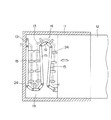
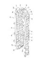
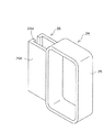
本発明の実施例1を図1〜図3に基づいて説明する。図1はケース本体と引出しユニットとの間に装架されたケーブル類の案内保持具の概念図であり、図2は引出し用ケーブル類の案内保持具の斜視図であり、図3はケーブル類を支持する保持枠の斜視図である。
【0011】
ケース本体11には、引出しユニット12が引き出し自在に収納されている。このケース本体11は、例えばオフィスで使用される机であり、引出しユニット12は机の下に収納され、必要なときに引き出すことが可能なOA機器用の引出しあるいはトレイ等である。ここでいうOA機器とは、パソコン本体、モニター、キーボード、プリンター等である。
【0012】
ケース本体11及び引出しユニット12としては、上記のようなものに限らず、基台と該起台に設けられた一般的な電気機械器具が配置されるトレイ、引出しでもよく、ケース本体と引出しユニットとの間に電源コード、信号の入出力ケーブル、センサの信号線、光ファイバー、流体用パイプ、これらを束ねたもの等のケーブル類を装架する必要があるものであればどのような態様のものであっても構わない。
【0013】
ケース本体11の背面内側と該ケース本体11内に引き出し自在に収納した引出しユニット12の背面外側との間に、電源コードや信号ケーブル等のケーブル類13が案内保持具14に保持されて装架されている。
【0014】
ケーブル類の案内保持具14は、概略、保持枠24が取り付けられた直線状アーム部材15と、この直線状アーム部材15どうしを屈曲可能に連結するヒンジ部材19とで構成され、このヒンジ部材19によりケーブル類13が湾曲状に屈曲可能となる。
【0015】
直線状アーム部材15は、図2に示すように、離間対向する直線状のアーム16と、このアーム16間に複数個取り付けられた縦桟17とからなり、直線状アーム部材15の両端部には、連結ピン23が挿入されるピン孔15aが設けられている。すなわち、一方のピン孔15aはアーム16の一端部に、他方のピン孔(図示略)は膨出部18に穿設されている。この直線状アーム部材15の縦桟17に適宜のピッチ間隔でケーブル類を支持する保持枠24が着脱可能に取り付けられる。
【0016】
ヒンジ部材19は、図2に示すように、直線状アーム部材15のアーム16に比較して短い一対のアーム20で形成され、縦桟21、膨出部22を備えている。ヒンジ部材19の両端部には、それぞれ連結ピン23が挿入されるピン孔19a、19bが設けられている。すなわち、一方のピン孔19aはアーム20の一端部に、他方のピン孔19bは膨出部22に穿設されている。このヒンジ部材19には、適宜、ケーブル類を支持する保持枠24が着脱可能に取り付けられる。
【0017】
保持枠24は、図3に示すように、枠体25と、この枠体25の一側に形成された取り付け部26とからなり、取り付け部26は先端に係合部26aを有する一対のプレート26bからなる。この保持枠24は、直線状アーム部材15の縦桟17及びヒンジ部材19の縦桟21にそれぞれ取り付け部26を嵌着することにより容易に取り付けられる。
【0018】
この実施例1では、保持枠24の枠体25がケーブル類13を閉鎖囲繞する一体のものとして説明したが、ケーブル類13を保持枠24の側方又は上方から挿脱できるように、図8又は図9に示すような形状のものとしてもよい。この場合、ケーブル類13の取り替え、追加等を容易に行うことができるようになる。
【0019】
上記の直線状アーム部材15及びヒンジ部材19とで構成されるケーブル類の案内保持具14は、複数の直線状アーム部材15どうしが適宜数のヒンジ部材19を介在させて連結ピン23で連結されることにより形成される。この場合、ケーブル類の案内保持具14の始端部及び終端部には、固定部材として機能するヒンジ部材19が連結され、このヒンジ部材19がケース本体11及び引出しユニット12にそれぞれ取り付けられる。
【0020】
上記構成からなるケーブル類の案内保持具14は、次の作用効果を奏する。ケース本体11と該ケース本体内に引き出し自在に収納した引出しユニット12との間に装架されたケーブル類13は、直線状アーム部材15あるいはヒンジ部材19に取り付けられた保持枠24に支持される。このケーブル類13を支持した案内保持具14は、引出しユニット12の出し入れに伴ってケーブル類13を保持しつつ屈曲移動する。
【0021】
この場合、ケーブル類13は保持枠24に支持されて拘束されていないことにより、案内保持具14が屈曲しても、ケーブル類に過大な張力が加わることがないので、張力による断線が防止される。また、屈曲部においても、一対のアーム20からなるヒンジ部材19を介在させて直線状アーム部材15どうしが離間した2本の連結ピン23で連結されるので、ケーブル類13が湾曲状に屈曲可能となり、ケーブル類13の鋭角屈曲による断線も防止される。
【0022】
ケーブル類13を支持する保持枠24は、直線状アーム部材15の縦桟17及びヒンジ部材19の縦桟21にそれぞれ取り付け部26により着脱可能に取り付けられているので、異なった大きさの保持枠24に変更するだけで、ケーブル類の径や本数が異なるサイズ違いのケ−ブル類13を保持できるようになる。
【0023】
また、保持枠24は、直線状アーム部材15の縦桟17及びヒンジ部材19の縦桟21にそれぞれ取り付け部26を嵌着することにより取り付けられるので、直線状アーム部材15の表裏両面のいずれにも取り付けることができ、保持枠24のサイズを変更することなく多数のケーブル類を保持することができる。
【0024】
ケーブル類13を支持する保持枠24は、枠体内部にケーブル類を支持するだけであるため、枠体、すなわち保持枠を単純な構造とすることができ、枠体の大きさを変えるだけでサイズ違いのケ−ブル類13に対応させることができる。
【0025】
さらに、直線状アーム部材15は、離間対向する直線状のアーム16間に縦桟17が複数個取り付けられて形成され、この縦桟17に保持枠24が取り付けられるので、縦桟17間の空間部により通風状態が良好となり、ケーブル類13の放熱を効率よく行うことができる。
【0026】
本発明の実施例2を図4〜図6に基づいて説明する。この実施例2のケーブル類の案内保持具は、前記実施例1のケーブル類の案内保持具14において、直線状アーム部材15、ヒンジ部材19、及び固定部材として機能するヒンジ部材19を変更したものに相当する。そこで、実施例2のケーブル類の案内保持具(全体図は図示略)について、前記実施例1のケーブル類の案内保持具において変更した部材を主として説明する。
【0027】
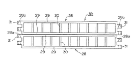
直線状アーム部材28は、図4に示すように、離間対向する直線状のアーム29と、このアーム29間に複数個取り付けられた縦桟30とからなり、直線状アーム部材28の両端部には、連結ピンが挿入されるピン孔28aが設けられている。すなわち、ピン孔28aは直線状アーム部材28の両端部に形成された膨出部31に穿設されている。前記実施例1と同様に、この直線状アーム部材28の縦桟30に適宜のピッチ間隔でケーブル類を支持する保持枠が着脱可能に取り付けられる。
【0028】
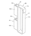
ヒンジ部材32は、図5(A),(B)に示すように、直線状アーム部材28のアーム29に比較して短い一対のアーム33で形成され、縦桟34及び上下2段の膨出部35を備えている。ヒンジ部材32の両端部には、それぞれ連結ピンが挿入されるピン孔32aが設けられている。前記実施例1と同様に、このヒンジ部材32の縦桟34には、適宜にケーブル類を支持する保持枠が着脱可能に取り付けられる。
【0029】
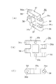
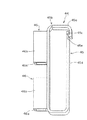
ケーブル類の案内保持具の始端部及び終端部には、ケース本体及び引出しユニットに案内保持具を取り付ける固定部材36が連結される。この固定部材36は、図6(A),(B),(C)に示されるように、ヒンジ部材32と略々同一外郭形状のもので、ケース本体又は引出しユニットへの取付用の取付孔37aを有する一対のアーム37で形成され、上下2段の膨出部38を備えている。また、固定部材36の両端部には、それぞれ連結ピンが挿入されるピン孔36aが設けられている。
【0030】
この実施例2のケーブル類の案内保持具は、前記実施例1と同様に、複数の直線状アーム部材28どうしが適宜数のヒンジ部材32を介在させて連結ピンで連結されることにより形成される。この場合、ケーブル類の案内保持具の始端部及び終端部には、固定部材36が連結ピンで連結して設けられ、この固定部材36がケース本体及び引出しユニットにそれぞれ取り付けられる。そして、この実施例2のケーブル類の案内保持具は、前記実施例1のケーブル類の案内保持具と同じ作用効果を奏する。
【0031】
本発明の実施例3を図7、図8に基づいて説明する。この実施例3のケーブル類の案内保持具は、前記実施例2の直線状アーム部材が上下に複数重ねて形成されたもので、以下、前記実施例2と共通する部材には同一符号を付して説明する。
【0032】
ケーブル類の案内保持具(図示略)を構成する直線状アーム部材39は、直線状アーム部材28が上下に重ねられて形成され、前記実施例2と同様に、直線状アーム部材28がそれぞれ適宜数のヒンジ部材を介在させて連結ピンで連結される。この場合、連結ピンは上下の直線状アーム部材28,28及びヒンジ部材それぞれのピン孔を貫通する通しピンとする。また、直線状アーム部材39は、直線状アーム部材28を2つ以上重ねて形成したものでもよく、さらに複数の直線状アーム部材28を重ねて一体に形成したものでもよい。
【0033】
ケーブル類を支持する保持枠40は、図8に示すように、枠体41と、この枠体41の一側上下に形成された取り付け部42,42とからなり、取り付け部42は先端に係合部42aを有する一対のプレート42bからなる。この保持枠40は、直線状アーム部材39の上下に亘る長さで、直線状アーム部材28,28の縦桟30,30及びヒンジ部材(図示略)の縦桟にそれぞれ取り付け部42を嵌着することにより着脱可能に取り付けられる。
【0034】
また、保持枠40は、ケーブル類を側方から挿脱できるように、上枠41aに対して側枠41bが弾性変形可能となっている。この保持枠40は、収納部が大きくなるため、ケーブル類の本数が多い場合に好適であると共に、ケーブル類の取り替え、追加時に挿脱が容易となる。
【0035】
上記実施例3における保持枠の変形例を図9に示す。ケーブル類を支持する枠状の保持枠44は、枠体45と、この枠体45の一側上下に形成された取り付け部46,46とからなり、取り付け部46は先端に係合部46aを有する一対のプレート46bからなる。この保持枠44は、直線状アーム部材39の上下に亘る長さで、直線状アーム部材28,28の縦桟30,30及びヒンジ部材(図示略)の縦桟にそれぞれ取り付け部46を嵌着することにより着脱可能に取り付けられる。
【0036】
この保持枠44は、ケーブル類を上方から挿脱できるように、上枠45aが屈曲部45bを支点にして開閉可能となっている。この上枠45aはフック45cを備え、このフック45cが側枠45dの係合部45eに係合する。この保持枠44は、収納部が大きくなるため、ケーブル類の本数が多い場合に好適であると共に、ケーブル類の取り替え、追加時に挿脱が容易となる。
【0037】
なお、この実施例3では、直線状アーム部材39に取り付けられる保持枠として、ケーブル類を側方又は上方から挿脱できる保持枠について説明したが、前記実施例1のように、保持枠の枠体がケーブル類を閉鎖囲繞する一体のもの、あるいは図10に示す保持枠のように上部が開放されたものでもよい。また、保持枠を直線状アーム部材39の上下に亘る長さのものとしないで、上下に重ねた直線状アーム部材28,28にそれぞれ別々に取り付けられる大きさの保持枠としてもよい。
【0038】
本発明の実施例4を図10に基づいて説明する。この実施例4のケーブル類の案内保持具(図示略)は、前記実施例1〜3と同様に、複数の直線状アーム部材48が適宜数のヒンジ部材を介在させて連結ピンで連結されることにより形成される。
【0039】
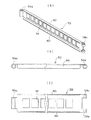
直線状アーム部材48は、膨出部50を有する長尺板状のアーム49からなり、両端部には連結ピンが挿入されるピン孔48aが設けられている。まず、同図左方に示す保持枠52について説明する。保持枠52は上部が開放された枠体53と、この枠体53の一側に形成された取り付け部54とからなり、この取り付け部54は一対のピン部材54a,54aからなる。
【0040】
また、アーム49には貫通孔51が穿設され、この貫通孔51にピン部材54a,54aが嵌入されることにより、保持枠52が直線状アーム部材48に着脱可能に取り付けられる。この保持枠52は、上部が開放されていることにより、ケーブル類の挿脱を容易に行うことができる共に、保持枠52の取替えを容易に行うことできる。
【0041】
次に、図10の右方に示す保持枠55について説明する。保持枠55は上方が開放された枠体56と、この枠体56の一側に形成された取り付け部57とからなり、この取り付け部57は抱持枠57aを備え、抱持枠57aを前記長尺板状のアーム49に係合することにより、保持枠55は直線状アーム部材48に着脱可能に取り付けられる。この保持枠55は、上部が開放されていることにより、ケーブル類の挿脱を容易に行うことができる共に、保持枠55の取替えを容易に行うことできる。
【0042】
この実施例4のケーブル類の案内保持具(図示略)は、取り付け部54により保持枠52が直線状アーム部材48に取り付けられ、あるいは抱持枠57aにより保持枠57が直線状アーム部材48に取り付けられるので、保持枠52あるいは保持枠55を直線状アーム部材48の表裏両面のいずれにも取り付けることができ、保持枠52,55のサイズを変更することなく多数のケーブル類を保持することができるようになる。
【0043】
本発明の実施例5を図11に基づいて説明する。この実施例5のケーブル類の案内保持具(図示略)は、前記実施例1〜3と同様に、複数の直線状アーム部材59が適宜数のヒンジ部材を介在させて連結ピンで連結されることにより形成される。
【0044】
直線状アーム部材59は、一対のアーム60と、このアーム60間に設けられた縦桟61とからなる。直線状アーム部材59の両端部には連結ピンが挿入されるピン孔59aが形成されている。また、この直線状アーム部材59に着脱可能に取り付けられる保持枠は、前記実施例1〜3のいずれかの態様で取り付けられるものであればよく、例えば、前記実施例4の保持枠55のように、抱持枠57aを一対のアーム60に係合させることにより取り付けられる。
【0045】
以上、各実施例について説明したが、直線状アーム部材、ヒンジ部材、保持枠等は、合成樹脂、金属等いずれの材質のものとしても構わないが、合成樹脂製のものとすることが軽量化や低価格にできるため好ましい。
【0046】
【発明の効果】
以上説明したように、各請求項に係る本発明の引出し用ケーブル類の案内保持具は、ケーブル類を支持する保持枠が直線状アーム部材及びヒンジ部材に取り付けられ、直線状アーム部材が両端部にピン孔を有するヒンジ部材を介在させて連結ピンで連結されているので、引出しの出し入れに伴って直線状アーム部材が屈曲したとき、ケーブル類が拘束されないで保持枠に支持されているため、ケーブル類に過大な張力が加わるのを防止することができ、張力による断線を防止することができる。
【0047】
ケーブル類を支持する保持枠が直線状アーム部材及びヒンジ部材に着脱可能に取り付けられているので、ケーブル類の径、本数が異なるサイズ違いの場合、直線状アーム部材及びヒンジ部材を共通のものとして、ケーブル類のサイズに対応した保持枠のみを変更すればよく、コスト的に優れたものとすることができる。また、この保持枠も単に枠体で形成すればよいので、保持枠を簡単な構造のものとすることができる。
【0048】
直線状アーム部材が上下に複数重ねて設けられている場合は、多数のケーブル類を保持することができ、重ねる直線状アーム部材の数を変更することにより、ケーブル類の本数に対応させて、ケーブル類の案内保持具を形成することができる。また、保持枠がケーブル類を側方又は上方から挿脱することが可能である場合は、ケーブル類の取り替え、追加時に容易に挿脱を行うことができる。
【図面の簡単な説明】
【図1】本発明の実施例1を示し、引出し用ケーブル類の案内保持具の概念図である。
【図2】同上、案内保持具の斜視図である。
【図3】同上、保持枠の斜視図である。
【図4】実施例2を示し、直線状アーム部材の斜視図である。
【図5】同上、(A)はヒンジ部材の斜視図、(B)は同側面図である。
【図6】同上、(A)は固定部材の斜視図、(B)は同側面図、(C)は同平面図である。
【図7】実施例3を示し、直線状アーム部材の側面図である。
【図8】同上、保持枠の斜視図である。
【図9】同上、変形例である保持枠の斜視図である。
【図10】実施例4を示し、直線状アーム部材の斜視図である。
【図11】実施例5を示し、(A)は直線状アーム部材の斜視図、(B)は同平面図、(C)は同側面図である。
【図12】従来の引出し用ケーブル類の案内保持具の概念図である。
【符号の説明】
11・・・ケース本体 12・・・引出しユニット 13・・・ケーブル類
14・・・案内保持具 15・・・直線状アーム部材 15a・・・ピン孔 16・・・アーム 17・・・縦桟 18・・・膨出部 19・・・ヒンジ部材 19a、19b・・・ピン孔 20・・・アーム 21・・・縦桟 22・・・膨出部 23・・・連結ピン 24・・・保持枠
25・・・枠体 26・・・取り付け部 26a・・・係合部 26b・・・プレート 28・・・直線状アーム部材 28a・・・ピン孔
29・・・アーム 30・・・縦桟 31・・・膨出部 32・・・ヒンジ部材 32a・・・ピン孔 33・・・アーム 34・・・縦桟 35・・・膨出部 36・・・固定部材 36a・・・ピン孔 37・・・アーム 37a・・・取付孔 38・・・膨出部 39・・・直線状アーム部材 40・・・保持枠 41・・・枠体 41a・・・上枠 41b・・・側枠 42・・・取り付け部 42a・・・係合部 42b・・・プレート 44・・・保持枠 45・・・枠体 45a・・・上枠
45b・・・屈曲部 45c・・・フック 45d・・・側枠 45e・・・係合部 46・・・取り付け部 46a・・・係合部 46b・・・プレート 48・・・直線状アーム部材 48a・・・ピン孔 49・・・アーム 50・・・膨出部 51・・・貫通孔 52・・・保持枠
53・・・枠体 54・・・取り付け部 54a・・・ピン部材 55・・・保持枠 56・・・枠体 57・・・取り付け部 57a・・・抱持枠 59・・・直線状アーム部材 59a・・・ピン孔 60・・・アーム 61・・・縦桟[0001]
TECHNICAL FIELD OF THE INVENTION
BACKGROUND OF THE
[0002]
[Prior art]
FIG. 13 shows a drawer
[0003]
[Problems to be solved by the invention]
Since the sheet metal support 5 is attached to the hinge 7 having one pin 7b as a pivot shaft, the two sheet metal supports 5 of the
[0004]
In addition, since the cables 4 are fixed to the sheet metal support 5 with the
[0005]
As a means for solving the above-mentioned problem, a cable protection guide for drawers has been proposed (Japanese Patent Application No. 2002-190409, filed on June 28, 2002). This drawer cable protection guide guide connects a long box-shaped linear support member having an opening / closing lid through which cables can be inserted / removed from above with a bending member formed of a link so that the cable can be bent at a predetermined curvature or more. It is composed.
[0006]
The drawer cable protection guide having such a configuration is an excellent one that prevents breakage of the cables at the time of bending, but has a long box shape different in size according to the diameter and number of cables. There is a problem that it is disadvantageous in terms of cost because it is necessary to arrange various types of linear support members.
[0007]
Therefore, the present invention solves the above-mentioned problems of the prior art, and can prevent excessive tension from being applied to the cables when the drawer unit is taken in and out, and the diameter and the number of the cables are different. Even in such a case, an object of the present invention is to provide a guide holder for a cable for drawing out which can be easily changed to a holding frame suitable for the size of the cables, and the holding frame can also have a simple structure. I do.
[0008]
[Means for Solving the Problems]
In order to achieve the above object, the present invention provides, as a means for solving the above problems, a method in which cables are supported by a holding frame attached to a linear arm member, and the linear arm members are connected via a hinge member. It was made.
The present invention according to
According to a second aspect of the present invention, in the guide holder for the pull-out cables, a plurality of the linear arm members are provided one above the other.
According to a third aspect of the present invention, in the guide holder for the drawer cables, the holding frame is configured such that the cables can be inserted and removed from a side or from above.
[0009]
[Action]
The guide holder for pull-out cables of the present invention according to each claim has at least two pin holes at both ends where a connecting pin is inserted, and a holding frame for supporting the cables is detachably attached. It has a linear arm member and a hinge member having a pin hole at each end for inserting a connecting pin, and a detachable mounting of a holding frame for supporting cables and the like. By being interposed and connected by the connecting pin, the cable is bent while holding the cables as the drawer is taken in and out, so that when the drawer unit is taken in and out, the cables supported by the holding frame are excessively large. The tension is not applied, and the diameter of the cables and the number of cables differ by simply changing the attachment frame that is detachably attached, and then installing it. Ke - it is possible to hold the table such, it is possible to those of the simple structure also holding frame cables.
[0010]
BEST MODE FOR CARRYING OUT THE INVENTION
First Embodiment A first embodiment of the present invention will be described with reference to FIGS. FIG. 1 is a conceptual view of a guide holder for cables mounted between a case body and a drawer unit, FIG. 2 is a perspective view of a guide holder for drawer cables, and FIG. It is a perspective view of the holding frame which supports.
[0011]
A
[0012]
The case body 11 and the
[0013]
A
[0014]
The
[0015]
As shown in FIG. 2, the
[0016]
As shown in FIG. 2, the
[0017]
As shown in FIG. 3, the holding
[0018]
In the first embodiment, the
[0019]
In the
[0020]
The
[0021]
In this case, since the
[0022]
The holding frames 24 supporting the
[0023]
Further, the holding
[0024]
Since the holding
[0025]
Furthermore, the
[0026]
Second Embodiment A second embodiment of the present invention will be described with reference to FIGS. The cable guide holder according to the second embodiment is obtained by changing the
[0027]
As shown in FIG. 4, the
[0028]
As shown in FIGS. 5A and 5B, the
[0029]
A fixing
[0030]
The guide holder for cables of the second embodiment is formed by connecting a plurality of
[0031]
Third Embodiment A third embodiment of the present invention will be described with reference to FIGS. The guide holder for cables of the third embodiment is formed by vertically stacking a plurality of linear arm members of the second embodiment. Hereinafter, members common to the second embodiment are denoted by the same reference numerals. Will be explained.
[0032]
The
[0033]
As shown in FIG. 8, the holding
[0034]
The holding
[0035]
FIG. 9 shows a modification of the holding frame according to the third embodiment. The frame-shaped
[0036]
The upper frame 45a can be opened and closed with the
[0037]
In the third embodiment, as the holding frame to be attached to the
[0038]
Embodiment 4 of the present invention will be described with reference to FIG. In the cable guide holder (not shown) of the fourth embodiment, a plurality of
[0039]
The
[0040]
The
[0041]
Next, the holding
[0042]
In the cable guide holder (not shown) of the fourth embodiment, the holding
[0043]
Embodiment 5 of the present invention will be described with reference to FIG. In the cable guide holder (not shown) of the fifth embodiment, a plurality of
[0044]
The
[0045]
Although the embodiments have been described above, the linear arm member, the hinge member, the holding frame, and the like may be made of any material such as a synthetic resin and a metal. It is preferable because the price can be reduced.
[0046]
【The invention's effect】
As described above, the guide and holding device for pull-out cables according to the present invention according to the claims has a holding frame for supporting the cables attached to the linear arm member and the hinge member, and the linear arm member has both ends. Since it is connected by a connecting pin with a hinge member having a pin hole interposed therebetween, when the linear arm member is bent with the insertion and extraction of the drawer, the cables are supported by the holding frame without being restrained, Excessive tension can be prevented from being applied to the cables, and disconnection due to the tension can be prevented.
[0047]
Since the holding frame for supporting the cables is detachably attached to the linear arm member and the hinge member, if the diameters and the number of the cables are different and the sizes are different, the linear arm member and the hinge member are shared. Only the holding frame corresponding to the size of the cables needs to be changed, and the cost can be improved. In addition, since the holding frame may be simply formed of a frame, the holding frame can have a simple structure.
[0048]
When a plurality of linear arm members are provided one above the other, it is possible to hold a large number of cables, and by changing the number of linear arm members to be overlapped, in accordance with the number of cables, A guide holder for cables can be formed. When the holding frame allows the cables to be inserted and removed from the side or from above, the cables can be easily inserted and removed when the cables are replaced or added.
[Brief description of the drawings]
FIG. 1 shows a first embodiment of the present invention and is a conceptual view of a guide holder for a cable for pulling out.
FIG. 2 is a perspective view of the guide holder according to the first embodiment;
FIG. 3 is a perspective view of the holding frame.
FIG. 4 is a perspective view of a linear arm member according to the second embodiment.
5A is a perspective view of the hinge member, and FIG. 5B is a side view of the hinge member.
6 (A) is a perspective view of a fixing member, FIG. 6 (B) is a side view thereof, and FIG. 6 (C) is a plan view thereof.
FIG. 7 shows the third embodiment and is a side view of a linear arm member.
FIG. 8 is a perspective view of the holding frame.
FIG. 9 is a perspective view of a modified example of the holding frame.
FIG. 10 is a perspective view of a linear arm member according to the fourth embodiment.
11A and 11B show a fifth embodiment, wherein FIG. 11A is a perspective view of a linear arm member, FIG. 11B is a plan view thereof, and FIG. 11C is a side view thereof.
FIG. 12 is a conceptual diagram of a conventional guide holder for pulling out cables.
[Explanation of symbols]
DESCRIPTION OF SYMBOLS 11 ... Case
Claims (3)
前記ケーブル類の案内保持具は、両端部に連結ピンが挿入されるピン孔を有すると共に、ケーブル類を支持する保持枠が着脱可能に取り付けられた少なくとも2つの直線状アーム部材と、両端部に連結ピンが挿入されるピン孔を有すると共に、ケーブル類を支持する保持枠が着脱可能に取り付けられるヒンジ部材とで構成され、
前記直線状アーム部材が前記ヒンジ部材を介在させて連結ピンで連結されることにより、前記引出しの出し入れに伴ってケーブル類を保持しつつ屈曲移動するようにしたことを特徴とする引出し用ケーブル類の案内保持具。A guide holder for a pull-out cable that guides and holds cables mounted between a case body and a drawer unit housed in the case body so as to be freely drawn out,
The guide holder for the cables has pin holes at both ends where a connecting pin is inserted, and at least two linear arm members to which a holding frame for supporting the cables is detachably attached, and at both ends. It has a pin hole into which the connecting pin is inserted, and a hinge member to which a holding frame for supporting cables is detachably attached,
A cable for drawing out, wherein the linear arm member is connected by a connecting pin with the hinge member interposed therebetween, whereby the linear arm member bends and moves while holding the cables as the drawer is taken in and out. Guide holder.
Priority Applications (6)
| Application Number | Priority Date | Filing Date | Title |
|---|---|---|---|
| JP2002327008A JP3716986B2 (en) | 2002-11-11 | 2002-11-11 | Guide holders for drawer cables |
| US10/690,310 US6896344B2 (en) | 2002-11-11 | 2003-10-21 | Guiding and holding jig for a flexible connector in a pull-out unit |
| DE10350304A DE10350304A1 (en) | 2002-11-11 | 2003-10-28 | Guide and holding device for a flexible connector of a pull-out unit |
| KR1020030078677A KR100776886B1 (en) | 2002-11-11 | 2003-11-07 | Drawing cable guiding and holding jig |
| CN200310114877.5A CN1291183C (en) | 2002-11-11 | 2003-11-11 | Guiding and holding clamp of drag cable |
| HK04105446.5A HK1062584B (en) | 2002-11-11 | 2004-07-22 | Drawing cable and/ or the like guiding and holding jig |
Applications Claiming Priority (1)
| Application Number | Priority Date | Filing Date | Title |
|---|---|---|---|
| JP2002327008A JP3716986B2 (en) | 2002-11-11 | 2002-11-11 | Guide holders for drawer cables |
Publications (2)
| Publication Number | Publication Date |
|---|---|
| JP2004166345A true JP2004166345A (en) | 2004-06-10 |
| JP3716986B2 JP3716986B2 (en) | 2005-11-16 |
Family
ID=32211977
Family Applications (1)
| Application Number | Title | Priority Date | Filing Date |
|---|---|---|---|
| JP2002327008A Expired - Fee Related JP3716986B2 (en) | 2002-11-11 | 2002-11-11 | Guide holders for drawer cables |
Country Status (5)
| Country | Link |
|---|---|
| US (1) | US6896344B2 (en) |
| JP (1) | JP3716986B2 (en) |
| KR (1) | KR100776886B1 (en) |
| CN (1) | CN1291183C (en) |
| DE (1) | DE10350304A1 (en) |
Cited By (8)
| Publication number | Priority date | Publication date | Assignee | Title |
|---|---|---|---|---|
| KR100776886B1 (en) | 2002-11-11 | 2007-11-19 | 가부시기가이샤쯔바기모도체인 | Drawing cable guiding and holding jig |
| JP2011183403A (en) * | 2010-03-04 | 2011-09-22 | Disco Corp | Processing apparatus |
| JP2012043325A (en) * | 2010-08-23 | 2012-03-01 | Fuji Electric Retail Systems Co Ltd | Automatic dispenser |
| JP2012156197A (en) * | 2011-01-24 | 2012-08-16 | Yaskawa Electric Corp | Electrical apparatus |
| JP2015174193A (en) * | 2014-03-17 | 2015-10-05 | 村田機械株式会社 | Loader device and machine tool |
| JP2019139181A (en) * | 2018-02-15 | 2019-08-22 | 株式会社フジクラ | Optical wiring unit, rack having optical wiring unit, and manufacturing method of rack having optical wiring unit |
| JP2020156140A (en) * | 2019-03-18 | 2020-09-24 | 富士ゼロックス株式会社 | Harness connection structure and electronic equipment |
| JP2021175910A (en) * | 2020-05-01 | 2021-11-04 | 株式会社ディスコ | Member for fixing transmission wire |
Families Citing this family (32)
| Publication number | Priority date | Publication date | Assignee | Title |
|---|---|---|---|---|
| AT411548B (en) * | 2002-05-10 | 2004-02-25 | Wien Kanal Abwassertech Gmbh | DEVICE FOR SUPPORT OR GUIDANCE OF CABLES IN CHANNELS |
| US7554819B2 (en) * | 2004-10-15 | 2009-06-30 | King Slide Works Co., Ltd. | Cable management arm assembly |
| HK1100628A2 (en) * | 2006-09-01 | 2007-09-28 | Sincere International Trading Co. Ltd. | Foldable clothes warmer |
| BRPI0622037B1 (en) * | 2006-09-27 | 2018-11-06 | Leoni Protec Cable Systems Gmbh | device for guiding a hose having at least one supply line |
| DE202007008106U1 (en) * | 2007-06-09 | 2008-10-23 | Liebherr-Hausgeräte Lienz Gmbh | Fridge and / or freezer |
| TW200912172A (en) * | 2007-09-06 | 2009-03-16 | King Slide Works Co Ltd | Supporting device of wire-arranging frame |
| US20110007464A1 (en) * | 2008-02-29 | 2011-01-13 | Leigh Kevin B | Modular system and retractable assembly for electronic devices |
| JP5067239B2 (en) * | 2008-03-28 | 2012-11-07 | 富士通株式会社 | Cable management device and electronic device device |
| DE102008019334B4 (en) * | 2008-04-16 | 2010-07-15 | Khs Ag | Supply line reservoir |
| CN201263269Y (en) * | 2008-08-15 | 2009-06-24 | 鸿富锦精密工业(深圳)有限公司 | cable management rack |
| US7984605B2 (en) * | 2008-09-10 | 2011-07-26 | Netapp, Inc. | Cable chain return system and associated methods |
| TWI357793B (en) * | 2008-09-25 | 2012-02-01 | Inventec Corp | Rack-mount cabinet |
| CN101741045B (en) * | 2008-11-20 | 2011-08-17 | 英业达股份有限公司 | Pulling device |
| DE102010003282B4 (en) * | 2010-03-25 | 2015-08-20 | Trumpf Werkzeugmaschinen Gmbh + Co. Kg | Cable guide device, in particular energy chain |
| CN102264211A (en) * | 2010-05-31 | 2011-11-30 | 鸿富锦精密工业(深圳)有限公司 | cable management device |
| TWI491345B (en) * | 2010-12-31 | 2015-07-01 | Hon Hai Prec Ind Co Ltd | Electronic device |
| TR201301119A2 (en) * | 2013-01-30 | 2014-08-21 | Bsh Ev Aletleri San Ve Tic As | A household appliance that includes a transmission element between a body and a door. |
| CN103970222B (en) * | 2013-02-05 | 2018-05-29 | 鸿富锦精密电子(天津)有限公司 | Cabinet |
| US8992241B2 (en) | 2013-04-30 | 2015-03-31 | International Business Machines Corporation | Flex circuit blind attachment apparatus and system |
| US9585468B2 (en) * | 2014-06-09 | 2017-03-07 | Knoll, Inc. | Cord management system for furniture |
| CN104536539A (en) * | 2014-12-04 | 2015-04-22 | 英业达科技有限公司 | Electronic device |
| CN105003599A (en) * | 2015-07-06 | 2015-10-28 | 浪潮电子信息产业股份有限公司 | A drag chain device for fixing cables |
| TWI610608B (en) * | 2015-09-11 | 2018-01-01 | 緯創資通股份有限公司 | Cable bridle, cable bridle mechanism and swapping system using the same |
| TWI603560B (en) * | 2016-08-12 | 2017-10-21 | 川湖科技股份有限公司 | Slide rail assembly and cable management device thereof |
| TWI616131B (en) * | 2016-08-31 | 2018-02-21 | 川湖科技股份有限公司 | Cable management device |
| CN107026422A (en) * | 2017-04-26 | 2017-08-08 | 招商局重工(江苏)有限公司 | The frock of whole beam movable cable connection between a kind of offshore engineering equipment |
| GB2566082B (en) * | 2017-09-04 | 2019-10-23 | Eschmann Holdings Ltd | Surgical tables |
| TWI649512B (en) * | 2018-02-07 | 2019-02-01 | 川湖科技股份有限公司 | Connecting device |
| JP6804490B2 (en) * | 2018-06-27 | 2020-12-23 | 矢崎総業株式会社 | Wire harness, power supply device equipped with the wire harness |
| CN111796218B (en) * | 2020-09-10 | 2020-12-01 | 四川华东电气集团有限公司 | Electronic transformer winding deformation tester |
| CN112453991B (en) * | 2020-11-30 | 2022-04-12 | 沈阳马卡智工科技有限公司 | Be applied to five machining center's of superelevation stroke formula wiring structure of turning back |
| KR102554411B1 (en) * | 2021-10-06 | 2023-07-11 | 네이버랩스 주식회사 | Delivery Robot |
Family Cites Families (17)
| Publication number | Priority date | Publication date | Assignee | Title |
|---|---|---|---|---|
| US4009919A (en) * | 1973-02-10 | 1977-03-01 | Schlafhorst & Co. | Traveling holder for textile coils |
| US4462565A (en) * | 1983-01-17 | 1984-07-31 | Lockheed Corporation | Erectable and retractable support for rolling conductor track |
| US4625936A (en) * | 1983-06-06 | 1986-12-02 | Sine Products Company | Flexible support and carrier assembly |
| DE3407169C2 (en) * | 1984-02-28 | 1986-01-23 | Kabelschlepp Gmbh, 5900 Siegen | Energy chain |
| JPS6296893U (en) | 1985-12-06 | 1987-06-20 | ||
| JPH0260746U (en) * | 1988-10-27 | 1990-05-07 | ||
| JPH02172650A (en) * | 1988-12-24 | 1990-07-04 | Fanuc Ltd | Reinforced telescopic cover |
| US5460441A (en) * | 1994-11-01 | 1995-10-24 | Compaq Computer Corporation | Rack-mounted computer apparatus |
| US5649415A (en) * | 1995-02-02 | 1997-07-22 | Hubbell Incorporated | Power supply chain and chain carriage system |
| DE19544931A1 (en) * | 1995-12-01 | 1997-06-05 | Kabelschlepp Gmbh | Chain link of an energy chain with additional body |
| DE29622349U1 (en) * | 1996-12-23 | 1998-04-23 | Igus Spritzgußteile für die Industrie GmbH, 51147 Köln | Energy supply chain |
| GB9724402D0 (en) * | 1997-11-19 | 1998-01-14 | Mansign Mining Equipment Ltd | Cable/hose handling chain |
| US6425238B1 (en) * | 1998-05-05 | 2002-07-30 | Igus Spritzgussteile für die Industrie GmbH | Energy guiding chain |
| US6142590A (en) * | 1999-04-05 | 2000-11-07 | Central Industrial Supply Company | Two U vertical height keyboard and flatscreen drawer for a server system rack |
| US6349534B1 (en) * | 1999-09-03 | 2002-02-26 | A&A Manufacturing Co., Inc. | Metal composite cable carrier |
| JP4052774B2 (en) | 1999-12-17 | 2008-02-27 | 日東工業株式会社 | Linkable cable guide |
| JP3716986B2 (en) | 2002-11-11 | 2005-11-16 | 株式会社椿本チエイン | Guide holders for drawer cables |
-
2002
- 2002-11-11 JP JP2002327008A patent/JP3716986B2/en not_active Expired - Fee Related
-
2003
- 2003-10-21 US US10/690,310 patent/US6896344B2/en not_active Expired - Lifetime
- 2003-10-28 DE DE10350304A patent/DE10350304A1/en not_active Withdrawn
- 2003-11-07 KR KR1020030078677A patent/KR100776886B1/en not_active Expired - Fee Related
- 2003-11-11 CN CN200310114877.5A patent/CN1291183C/en not_active Expired - Fee Related
Cited By (10)
| Publication number | Priority date | Publication date | Assignee | Title |
|---|---|---|---|---|
| KR100776886B1 (en) | 2002-11-11 | 2007-11-19 | 가부시기가이샤쯔바기모도체인 | Drawing cable guiding and holding jig |
| JP2011183403A (en) * | 2010-03-04 | 2011-09-22 | Disco Corp | Processing apparatus |
| JP2012043325A (en) * | 2010-08-23 | 2012-03-01 | Fuji Electric Retail Systems Co Ltd | Automatic dispenser |
| JP2012156197A (en) * | 2011-01-24 | 2012-08-16 | Yaskawa Electric Corp | Electrical apparatus |
| JP2015174193A (en) * | 2014-03-17 | 2015-10-05 | 村田機械株式会社 | Loader device and machine tool |
| JP2019139181A (en) * | 2018-02-15 | 2019-08-22 | 株式会社フジクラ | Optical wiring unit, rack having optical wiring unit, and manufacturing method of rack having optical wiring unit |
| JP2020156140A (en) * | 2019-03-18 | 2020-09-24 | 富士ゼロックス株式会社 | Harness connection structure and electronic equipment |
| JP7230605B2 (en) | 2019-03-18 | 2023-03-01 | 富士フイルムビジネスイノベーション株式会社 | Harness connection structure and electronic equipment |
| JP2021175910A (en) * | 2020-05-01 | 2021-11-04 | 株式会社ディスコ | Member for fixing transmission wire |
| JP7378903B2 (en) | 2020-05-01 | 2023-11-14 | 株式会社ディスコ | Transmission line fixing member |
Also Published As
| Publication number | Publication date |
|---|---|
| CN1499118A (en) | 2004-05-26 |
| KR20040041508A (en) | 2004-05-17 |
| HK1062584A1 (en) | 2004-11-12 |
| CN1291183C (en) | 2006-12-20 |
| KR100776886B1 (en) | 2007-11-19 |
| JP3716986B2 (en) | 2005-11-16 |
| DE10350304A1 (en) | 2004-05-27 |
| US6896344B2 (en) | 2005-05-24 |
| US20040090159A1 (en) | 2004-05-13 |
Similar Documents
| Publication | Publication Date | Title |
|---|---|---|
| JP2004166345A (en) | Guiding holder for cables of drawer | |
| JP4419470B2 (en) | Optical fiber cable wiring accommodation structure, optical connector accommodation method, and optical connector connection method | |
| JP5235377B2 (en) | Assembly desk and assembly desk assembly | |
| JP6202642B2 (en) | Device, cable guide device, cable holding member | |
| CN214335308U (en) | Rack mountable optical fiber splice enclosure | |
| TW201424521A (en) | Rack-mount server | |
| CN113311911A (en) | Heat dissipation device and case | |
| JP2020131002A (en) | Slide rail mechanism and its supporting assembly | |
| EP2397879B1 (en) | Organizer for an optical fibre cable and method of providing a splice for an optical fibre cable | |
| JP2007201332A (en) | Cable holding member for cabinets for storing electrical and electronic equipment | |
| JP2013145804A (en) | Electronic apparatus housing cabinet | |
| JP5405260B2 (en) | Electrical equipment storage box | |
| JP2007093760A (en) | Rack unit wiring holding shelf | |
| JP6994008B2 (en) | Slide rail mechanism and its support assembly | |
| JP2006228340A (en) | Magnetic disk mounting device | |
| JP3922614B2 (en) | Drawer unit | |
| JP4036330B2 (en) | Splice unit | |
| CN216162330U (en) | Communication cabinet cable rack | |
| JP4602447B2 (en) | Retention member, mounting member, mounting base for optical wiring board, optical wiring board | |
| JP6796283B2 (en) | How to remove the transmission device, cable guide set, and board | |
| CN223180461U (en) | Optical fiber distribution frame convenient for wiring | |
| WO2020134172A1 (en) | Plug-in frame and communication device | |
| CN217591348U (en) | Modularization rack | |
| JP6598648B2 (en) | Cable holding member and electrical / electronic equipment storage box | |
| JP3819373B2 (en) | Optical frame and optical wiring system |
Legal Events
| Date | Code | Title | Description |
|---|---|---|---|
| A131 | Notification of reasons for refusal |
Free format text: JAPANESE INTERMEDIATE CODE: A131 Effective date: 20050711 |
|
| A521 | Written amendment |
Free format text: JAPANESE INTERMEDIATE CODE: A523 Effective date: 20050802 |
|
| TRDD | Decision of grant or rejection written | ||
| A01 | Written decision to grant a patent or to grant a registration (utility model) |
Free format text: JAPANESE INTERMEDIATE CODE: A01 Effective date: 20050824 |
|
| A61 | First payment of annual fees (during grant procedure) |
Free format text: JAPANESE INTERMEDIATE CODE: A61 Effective date: 20050824 |
|
| R150 | Certificate of patent or registration of utility model |
Free format text: JAPANESE INTERMEDIATE CODE: R150 Ref document number: 3716986 Country of ref document: JP Free format text: JAPANESE INTERMEDIATE CODE: R150 |
|
| FPAY | Renewal fee payment (event date is renewal date of database) |
Free format text: PAYMENT UNTIL: 20090909 Year of fee payment: 4 |
|
| FPAY | Renewal fee payment (event date is renewal date of database) |
Free format text: PAYMENT UNTIL: 20090909 Year of fee payment: 4 |
|
| FPAY | Renewal fee payment (event date is renewal date of database) |
Free format text: PAYMENT UNTIL: 20100909 Year of fee payment: 5 |
|
| FPAY | Renewal fee payment (event date is renewal date of database) |
Free format text: PAYMENT UNTIL: 20110909 Year of fee payment: 6 |
|
| FPAY | Renewal fee payment (event date is renewal date of database) |
Free format text: PAYMENT UNTIL: 20110909 Year of fee payment: 6 |
|
| FPAY | Renewal fee payment (event date is renewal date of database) |
Free format text: PAYMENT UNTIL: 20120909 Year of fee payment: 7 |
|
| FPAY | Renewal fee payment (event date is renewal date of database) |
Free format text: PAYMENT UNTIL: 20130909 Year of fee payment: 8 |
|
| LAPS | Cancellation because of no payment of annual fees |